products catalogproducts catalog conductive polymer ... and specifications are each subject to...
TRANSCRIPT
Conductive Polymer Tantalum Solid Capacitors
Products CatalogProducts Catalog
2018.6 http://industrial.panasonic.com/ww/products/capacitors/polymer-capacitors/poscap
2018

Design and specifications are each subject to change without notice. Ask factory for the current technical specifications before purchase and/or use.
Should a safety concern arise regarding this product, please be sure to contact us immediately.
——— Notices ———
■ Applicable Laws and Regulations● This product complies with the RoHS Directive (Restriction of the use of certain Hazardous substances in
electrical and electronic equipment (DIRECTIVE 2011/65/EU).
● No Ozone Depleting Chemicals(ODC's), controlled under the Montreal Protocol Agreement, are used in producing this product.
● We do not PBBs or PBDEs as brominated flame retardants.
● Export procedure which followed export related regulations, such as foreign exchange and a foreign trade method, on the occasion of export of this product Thank you for your consideration.
■ Limited applications● This capacitor is designed to be used for electronics circuits such as audio/visual equipment, home
appliances, computers and other office equipment, optical equipment, measuring equipment.
● High reliability and safety are required [ be / a possibility that incorrect operation of this product may do harm to a human life or property ] more. When use is considered by the use, the delivery specifications which suited
the use separately need to be exchanged.
——— Items to be observed ———
● This specification guarantees the quality and performance of the product as individual components.
Before use, check and evaluate their compatibility with installed in your products.
● Do not use the products beyond the specifications described in this document.
■ For specifi cations
● Install the following systems for a failsafe design to ensure safety if these products are to be used in equipment where a defect in these products may cause the loss of human life or other signification damage,
such as damage to vehicles (automobile, train, vessel), traffic lights, medical equipment, aerospace equipment,
electric heating appliances, combustion/ gas equipment, rotating rotating equipment, and disaster/crime
prevention equipment.
· The system is equipped with a protection circuit and protection device.
· The system is equipped with a redundant circuit or other system to prevent an unsafe status in the event of
a single fault.
■ Conditions of use
● Before using the products, carefully check the effects on their quality and performance, and determined whether or not they can be used. These products are designed and manufactured for general-purpose and
standard use in general electronic equipment. These products are not intended for use in the following special
conditions.
(1) In liquid, such as Water, Oil, Chemicals, or Organic solvent.
(2) In direct sunlight, outdoors, or in dust.
(3) In vapor, such as dew condensation water of resistive element, or water leakage, salty air, or air with a
high concentration corrosive gas, such as Cl2, H2S, NH3, SO2, or NOx.
(4) In an environment where strong static electricity or electromagnetic waves exist.
(5) Mounting or placing heat-generating components or inflammables, such as vinyl-coated wires, near
these products.
(6) Sealing or coating of these products or a printed circuit board on which these products are mounted,
with resin and other material.
(7) Using resolvent, water or water-soluble cleaner for flux cleaning agent after soldering. (In particular,
when using water or a water-soluble cleaning agent, be careful not to leave water residues)
(8) Using in the atmosphere which strays Acid or alkaline.
(9) Using in the atmosphere which there are excessive vibration and shock.
● Please arrange circuit design for preventing impulse or transitional voltage. Do not apply voltage, which exceeds the full rated voltage when the capacitors receive impulse voltage,
instantaneous high voltage, high pulse voltage etc.
● Our products there is a product are using an electrolyte solution. Therefore, misuse can result in rapid deterioration of characteristics and functions of each product. Electrolyte leakage damages printed circuit and
affects performance, characteristics, and functions of customer system.
Nov. 201500
Design and specifications are each subject to change without notice. Ask factory for the current technical specifications before purchase and/or use.
Should a safety concern arise regarding this product, please be sure to contact us immediately.
Conductive Polymer Tantalum Solid Capacitors
Guidelines and precautions (POSCAP)1. Circuit design
1.1 Prohibited circuitsSince problems can be expected, POSCAP cannot be used on the following circuits
(1) High impedance voltage retention circuits(2) Coupling circuit(3) Time constant circuits(4) Circuits greatly affected by leakage current(5) The circuit in which two or more POSCAP are connected in a series so as to raise the endurance voltage.
1.2 Failure and life-spanThe failure rate is 0.5 %✽ / 1000 h (Confidence level : 60 %) based on JIS C 5003.
The mainly failure modes are as follows.
✽ B2 size or less : 1.0 %
1.2-1 Contingency failureThe main causes of failure are thermal stresses cause by the soldering or thermal use environment, along with
heat stresses, electrical stresses or mechanical stresses. The most common failure mode is a short circuit.
In case a short circuit occurs, ensure safety by fully considering the followings.
(1) If POSCAP emit smoke, turn off the main power of the equipment. In this case, keep your face and
hands away from the area.
(2) It may take a few seconds to a few minutes before POSCAP emits smoke by the situation. Increase
safety by using a protective circuit.
(3) If the smoke comes into eyes, rinse immediately. If the smoke is inhaled, gargle immediately.
(4) In case a large current continues to flow after a short circuit, in the worst case, the shorted-out
section may ignite. For safety, install a redundant circuit or a protective circuit, etc.
1.2-2 Wear-out failure (lifetime)When lifetime exceeded the specified guarantee time of Endurance and Damp heat, electrolyte
might insulate and cause electric characteristic changed. This is called an open circuit. The electric
characteristics of capacitance and ESR may possibly change within the specified range in specifications
when it is used under the condition of the rated voltage, electric and mechanical performance. Please
note it when design.
1.3 Reduction of failure stressWhen POSCAP is used within the rated voltage, it shows a stable characteristic, but it may be damaged
in a short circuit when an overvoltage, for instance, is applied. The time to reach the failure mode can be
extended by using POSCAP with reduced environment temperature, ripple current and applied voltage.
Failure rate
In the case of the endurance which is 105 °C 2000 h.
0.5 %/1000 h (Environment temp. : 105 °C, Rated voltage or Category voltage applied)
In the case of the endurance which is 105 °C 1000 h or 125 °C 1000 h.
1.0 %/1000 h (Environment temp. : 105 °C, Rated voltage or Category voltage applied)
In the case of the endurance which is 85 °C 1000 h.
1.0 %/1000 h (Environment temp. : 85 °C, Rated voltage applied)
1.4 Check the rated performanceAfter checking the operation and installation environments, design the circuit so that it falls within the rated
performance range stipulated in this delivery specification.
1.5 Operating temperature and ripple current(a) Set the operating temperature so that it falls within the range stipulated in this delivery specification.(b) Do not apply current that exceeds the allowable ripple current. Ripple current should be controlled so that
surface temperature of a capacitor do not exceed the rated temperature. (For questions regarding TQC series, please contact us.)(c) Specified ESR is a value at the time of shipping from factory. ESR may change upon use conditions.
Jun. 201806
Design and specifications are each subject to change without notice. Ask factory for the current technical specifications before purchase and/or use.
Should a safety concern arise regarding this product, please be sure to contact us immediately.
Conductive Polymer Tantalum Solid Capacitors
1.6 Leakage currentEven when the soldering conditions fall within the range of this delivery specifications, leakage current
increases a little on occasion. It also increases a little during high temperature storage, high humidity storage
and temperature cycling with no voltage applied. In cases such as these, leakage current will decrease by
applying voltage under the condition of below the POSCAP's maximum operating temperature.
The speed at which the leakage current is restored is increased by applying voltage when the POSCAP's
temperature is close to the maximum operating temperature.
1.7 Rapid charge and discharge limitationRapid charge and discharge are restricted (for maintainance of high-proof reliability).
A protective circuit is recommended for when a rapid charge or discharge causes excessive rush current
since this is main cause of short circuit and large leakage current. Use a protective circuits in case the rush
current value exceeds 20 A✽.
Be sure to insert a protection resistor of about 1 kΩ for charge and discharge when measuring the leakage current.
✽ When TH series use under the ambient temperature more than 105 °C : 10 A
TPU series : 10 A
2. Mounting2.1 Protect circuit
The failure mode of POSCAP is the short mode. When it breaks down, short electric current flows to it. POSCAP gives off heat by this short current.Do the following consideration in design fully for the safety because it has a bad influence on the part around POSCAP due to this heat. ∙ A protective circuit and a protective device are set up, so as to make the system safer. ∙ A diffuse circuit and so on is set up, so as to make the system safer such as that a machine may not
break down as to the single trouble.
2.2 Considerations when solderingThe soldering conditions are to be within the range prescribed in this delivery specification.If the specifications are not followed, there is the possibility of degradation of electric characteristic and lifetime when soldering is conducted under conditions that are harsher that those stipulated.
2.3 OthersPOSCAP’s Electrical characteristics are affected by temperature and frequency fluctuations.Design circuits after checking the amount of fluctuation.
3. StorageIt is necessary to set an environment to prevent a trouble at the time of soldering by the degradation of solder ability or moisture's getting into the molding resin when POSCAP are stored.Please make storage of POSCAP sealing up in the reel and storage bag at the time of delivery in the following environment. Also, set storage period of unopened as 18 months or shorter after shipment from factory.Room temperature and room humidity (generally : 15 to 35 °C, 45 to 75% RH ) are desirable. Place where POSCAP is not exposed by direct sunshine.Please unseal storage bag just before mounting and use up POSCAP in the storage bag.
◇ Intellectual property rightWe, Panasonic Group are providing the product and service that customers can use without anxiety, and are
working positively on the protection of our products under intellectual property rights.
Representative patents relating to POSCAP are as follows:
US Patent Nos. 6168639 and 6313979
Floor life
Level Time Conditions
2a 4 weeks < 30 °C/60 %Rh
3 168 hours < 30 °C/60 %Rh
5 48 hours < 30 °C/60 %Rh
POSCAP is not compatible with JEDEC J-STD-020, J-STD-033
Jun. 201806

Conductive Polymer Tantalum Solid Capacitors
Line up

Conductive Polymer Tantalum Solid Capacitors
Line up
Conductive Polymer Tantalum Solid Capacitors
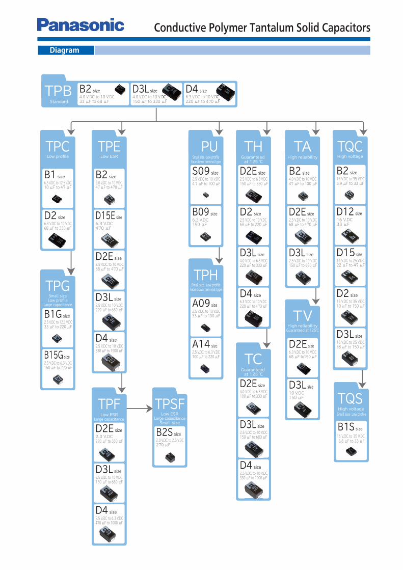
Diagram
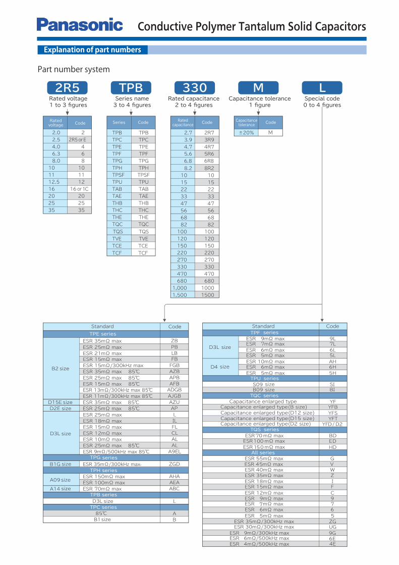
Explanation of part numbers
Part number system
Conductive Polymer Tantalum Solid Capacitors
Design and specifications are each subject to change without notice. Ask factory for the current technical specifications before purchase and/or use.
Should a safety concern arise regarding this product, please be sure to contact us immediately.
Conductive Polymer Tantalum Solid Capacitors
150 °C
200 °C
240 °C
Time (sec.)
40 s max
30 s max120 s max
Tem
pera
ture
on the s
urf
ace o
f cap
acito
r
5 s maxPeak temperature
60 smax
217 °C200 °C
150 °C
260 °C
6 s max
5 s max
Peak
temperature
Time (sec.)
90 s max180 s max60 smax
Tem
pera
ture
on the s
urf
ace o
f cap
acito
r
220 °C
180 °C
150 °C
250 °C
40 s max
30 s max120 s max60 s max
Time (sec.)
5 s maxPeak temperature
Tem
pera
ture
on the s
urf
ace o
f cap
acito
r
217 °C200 °C180 °C150 °C
250 °C
Time (sec.)
70 s max120 s max
60 s max
10 s maxPeak temperature
Tem
pera
ture
on the s
urf
ace o
f cap
acito
r
a ac
b
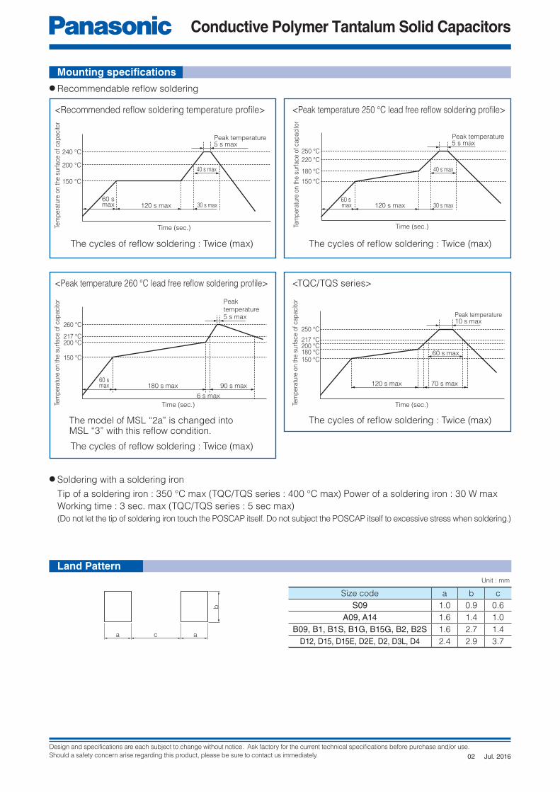
Mounting specifi cations
● Recommendable refl ow soldering
● Soldering with a soldering iron
Tip of a soldering iron : 350 °C max (TQC/TQS series : 400 °C max) Power of a soldering iron : 30 W max
Working time : 3 sec. max (TQC/TQS series : 5 sec max)
(Do not let the tip of soldering iron touch the POSCAP itself. Do not subject the POSCAP itself to excessive stress when soldering.)
<Peak temperature 260 °C lead free refl ow soldering profi le>
<Recommended refl ow soldering temperature profi le> <Peak temperature 250 °C lead free refl ow soldering profi le>
<TQC/TQS series>
The cycles of refl ow soldering : Twice (max)
The cycles of refl ow soldering : Twice (max)
The cycles of refl ow soldering : Twice (max)
The cycles of refl ow soldering : Twice (max)The model of MSL “2a” is changed intoMSL “3” with this refl ow condition.
Land Pattern
Size code a b c
S09 1.0 0.9 0.6
A09, A14 1.6 1.4 1.0
B09, B1, B1S, B1G, B15G, B2, B2S 1.6 2.7 1.4
D12, D15, D15E, D2E, D2, D3L, D4 2.4 2.9 3.7
Unit : mm
Jul. 201602
Design and specifications are each subject to change without notice. Ask factory for the current technical specifications before purchase and/or use.
Should a safety concern arise regarding this product, please be sure to contact us immediately.
Conductive Polymer Tantalum Solid Capacitors
Sprocket hole J
A
FK
tG H
DE
C
Component compartment(Polarity)
Direction of unreeling
(−)
(+)
B
W2W1
ABC
c
a
b
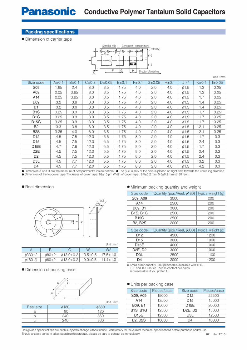
Packing specifi cations
● Dimension of carrier tape
● Reel dimension ● Minimum packing quantity and weight
● Dimension of packing case
● Units per packing case
Size code A±0.1 B±0.1 C±0.3 D±0.05 E±0.1 F±0.1 G±0.05 H±0.1 J+0.1 K±0.1 t±0.05
S09 1.65 2.4 8.0 3.5 1.75 4.0 2.0 4.0 f1.5 1.3 0.25
A09 2.05 3.65 8.0 3.5 1.75 4.0 2.0 4.0 f1.5 1.3 0.25
A14 2.05 3.65 8.0 3.5 1.75 4.0 2.0 4.0 f1.5 1.7 0.25
B09 3.2 3.8 8.0 3.5 1.75 4.0 2.0 4.0 f1.5 1.4 0.25
B1 3.2 3.8 8.0 3.5 1.75 4.0 2.0 4.0 f1.5 1.4 0.25
B1S 3.25 3.9 8.0 3.5 1.75 4.0 2.0 4.0 f1.5 1.7 0.25
B1G 3.25 3.9 8.0 3.5 1.75 4.0 2.0 4.0 f1.5 1.7 0.25
B15G 3.25 3.9 8.0 3.5 1.75 4.0 2.0 4.0 f1.5 1.7 0.25
B2 3.3 3.8 8.0 3.5 1.75 4.0 2.0 4.0 f1.5 2.1 0.25
B2S 3.25 4.0 8.0 3.5 1.75 4.0 2.0 4.0 f1.5 2.1 0.25
D12 4.5 7.5 12.0 5.5 1.75 8.0 2.0 4.0 f1.5 1.7 0.3
D15 4.5 7.5 12.0 5.5 1.75 8.0 2.0 4.0 f1.5 2.4 0.3
D15E 4.7 7.8 12.0 5.5 1.75 8.0 2.0 4.0 f1.5 1.7 0.3
D2E 4.5 7.5 12.0 5.5 1.75 8.0 2.0 4.0 f1.5 2.4 0.3
D2 4.5 7.5 12.0 5.5 1.75 8.0 2.0 4.0 f1.5 2.4 0.3
D3L 4.5 7.7 12.0 5.5 1.75 8.0 2.0 4.0 f1.5 3.2 0.3
D4 4.5 7.7 12.0 5.5 1.75 8.0 2.0 4.0 f1.5 4.2 0.3
Reel size f180 f330a 90 120b 240 360c 240 360
Size code Quantity (pcs./Reel, f180) Typical weight (g)
S09, A09 3000 200
A14 2500 200
B09, B1 3000 200
B1S, B1G 2500 200
B15G 2500 200
B2, B2S 2000 200
Size code Pieces/case
S09, A09 15000
A14 12500
B09, B1 15000
B1S, B1G 12500
B15G 12500
B2, B2S 10000
Size code Pieces/case
D12 22500
D15 15000
D15E 20000
D2E, D2 15000
D3L 12500
D4 10000
Size code Quantity (pcs./Reel, f330) Typical weight (g)
D12 4500 1200
D15 3000 1000
D15E 4000 1000
D2E, D2 3000 1000
D3L 2500 1100
D4 2000 1200
0
Unit : mm
Unit : mm
Unit : mm
A B C W1 W2
f330±2 f80±2 f13.0±0.2 13.5±0.5 17.5±1.0
f180 −3 f60±2 f13.0±0.2 9.0±0.5 11.4±1.00
✽ Small order quantity (500 pcs/reel) is available with TPE, TPF and TQC series. Please contact our sales representative if you prefer it.
● Dimension A and B are the measure of compartment's inside bottom. ● The (+) Polarity of the chip is placed on right side towards the unreeling direction.● Dimension of the topcover tape Thickness of cover tape: 62±10 μm Width of cover tape : 9.5±0.2 mm 5.5±0.2 mm (f180 reel)
Jul. 201602
Design and specifications are each subject to change without notice. Ask factory for the current technical specifications before purchase and/or use.
Should a safety concern arise regarding this product, please be sure to contact us immediately.
Conductive Polymer Tantalum Solid Capacitors
Lot. No.
R.Cap. code
R. Voltage code
Polarity
marking(+)
Lot. No.
R.Cap. code
R. Voltage code
Polarity marking(+)
W1
L
W
S
H
S
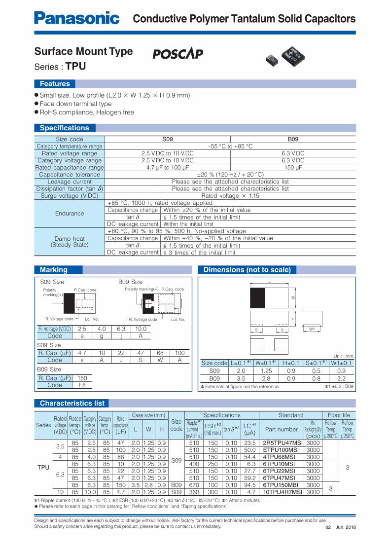
● Small size, Low profi le (L2.0 × W 1.25 × H 0.9 mm)● Face down terminal type● RoHS compliance, Halogen free
Specifi cations
Features
Marking Dimensions (not to scale)
Characteristics list
Size code S09 B09Category temperature range –55 °C to +85 °C
Rated voltage range 2.5 V.DC to 10 V.DC 6.3 V.DCCategory voltage range 2.5 V.DC to 10 V.DC 6.3 V.DC
Rated capacitance range 4.7 μF to 100 μF 150 μFCapacitance tolerance ±20 % (120 Hz / + 20 °C)
Leakage current Please see the attached characteristics listDissipation factor (tan d) Please see the attached characteristics list
Surge voltage (V.DC) Rated voltage × 1.15
Endurance
+85 °C, 1000 h, rated voltage appliedCapacitance change Within ±20 % of the initial value
tan d < 1.5 times of the initial limitDC leakage current Within the initial limit
Damp heat(Steady State)
+60 °C, 90 % to 95 %, 500 h, No-applied voltageCapacitance change Within +40 %, −20 % of the initial value
tan d < 1.5 times of the initial limitDC leakage current < 3 times of the initial limit
S09 Size
B09 SizeSize code L±0.1 ✽1 W±0.1 ✽1 H±0.1 S±0.1 ✽1 W1±0.1
S09 2.0 1.25 0.9 0.5 0.9
B09 3.5 2.8 0.9 0.8 2.2
R. Voltage (V.DC) 2.5 4.0 6.3 10.0Code e g j A
R. Cap. (μF) 4.7 10 22 47 68 100Code s A J S W A
R. Cap. (μF) 150Code E8
SeriesRatedvoltage(V.DC)
Ratedtemp.(°C)
Categoryvoltage
(V.DC)
Categorytemp.(°C)
Ratedcapacitance(μF)
Case size (mm)Size
code
Specifications Standard Floor life
L W HRipple ✽1 current(mAr.m.s.)
ESR ✽2
(mΩ max.)tan d ✽3 LC ✽4
(μA)Part number
Min. Packaging Q'ty(pcs)
Refl owTemp
< 260°C
Refl owTemp
< 250°C
TPU
2.585 2.5 85 47 2.0 1.25 0.9
S09
510 150 0.10 23.5 2R5TPU47MSI 3000
–3
85 2.5 85 100 2.0 1.25 0.9 510 150 0.10 50.0 ETPU100MSI 30004 85 4.0 85 68 2.0 1.25 0.9 510 150 0.10 54.4 4TPU68MSI 3000
6.3
85 6.3 85 10 2.0 1.25 0.9 400 250 0.10 6.3 6TPU10MSI 300085 6.3 85 22 2.0 1.25 0.9 510 150 0.10 27.7 6TPU22MSI 300085 6.3 85 47 2.0 1.25 0.9 510 150 0.10 59.2 6TPU47MSI 300085 6.3 85 150 3.5 2.8 0.9 B09 670 100 0.10 94.5 6TPU150MBI 3000
310 85 10.0 85 4.7 2.0 1.25 0.9 S09 360 300 0.10 4.7 10TPU4R7MSI 3000
✽1 Ripple current (100 kHz/ +45 °C ), ✽2 ESR (100 kHz/+20 °C) ✽3 tan d (120 Hz/+20 °C) ✽4 After 5 minutes
◆ Please refer to each page in this catarog for “Reflow conditions” and “Taping specifications”.
Unit : mm
✽1 ±0.2 : B09
S09 Size B09 Size
✽ Externals of fi gure are the reference.
Surface Mount Type
Series : TPU
Jun. 201802
Design and specifications are each subject to change without notice. Ask factory for the current technical specifications before purchase and/or use.
Should a safety concern arise regarding this product, please be sure to contact us immediately.
Conductive Polymer Tantalum Solid Capacitors
R.Cap. code
R. Voltage code
Year
Week
Polarity marking(+)
W1
H
L
W
S S
Polarity marking(+) R.Cap. code
R. Voltage code
Year
Week
W1
H
L
W
S S
Surface Mount Type
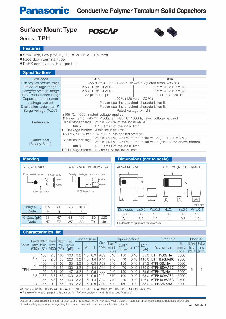
Series : TPH
● Small size, Low profi le (L3.2 × W 1.6 × H 0.9 mm)● Face down terminal type● RoHS compliance, Halogen free
Size code A09 A14Category temperature range –55 °C to +105 °C / –55 °C to +85 °C (Rated temp. +85 °C)
Rated voltage range 2.5 V.DC to 10 V.DC 2.5 V.DC to 6.3 V.DCCategory voltage range 2.5 V.DC to 10 V.DC 2.5 V.DC to 6.3 V.DC
Rated capacitance range 33 μF to 100 μF 100 μF to 220 μFCapacitance tolerance ±20 % (120 Hz / + 20 °C)
Leakage current Please see the attached characteristics listDissipation factor (tan d) Please see the attached characteristics list
Surge voltage (V.DC) Rated voltage × 1.15
Endurance
+105 °C, 1000 h rated voltage applied✽ Rated temp, +85 °C Products : +85 °C, 1000 h, rated voltage appliedCapacitance change Within ±20 % of the initial value
tan d < 1.5 times of the initial limitDC leakage current Within the initial limit
Damp heat(Steady State)
+60 °C, 90 % to 95 %, 500 h, No-applied voltage
Capacitance changeWithin +50 %, −20 % of the initial value (ETPH220MABC)Within +40 %, −20 % of the initial value (Except for above model)
tan d < 1.5 times of the initial limitDC leakage current < 3 times of the initial limit
R. Voltage (V.DC) 2.5 4.0 6.3 10.0
Code e g j A
R. Cap. (μF) 33 47 68 100 150 220
Code N7 S7 W7 A8 E8 J8
SeriesRatedvoltage(V.DC)
Ratedtemp.(°C)
Categoryvoltage
(V.DC)
Categorytemp.(°C)
Ratedcapacitance(μF)
Case size (mm)Size
code
Specifications Standard Floor life
L W HRipple ✽1 current(mAr.m.s.)
ESR ✽2
(mΩ max.)tan d ✽3 LC ✽4
(μA)Part number
Min. Packaging Q'ty(pcs)
Refl owTemp
< 260°C
Refl owTemp
< 250°C
TPH
2.5105 2.5 105 100 3.2 1.6 0.9 A09 510 150 0.10 25.0 ETPH100MHA 3000
3 3
85 2.5 85 220 3.2 1.6 1.4 A14 740 70 0.10 110.0 ETPH220MABC 2500
4105 4.0 105 68 3.2 1.6 0.9 A09 510 150 0.10 27.2 4TPH68MHA 3000 85 4.0 85 150 3.2 1.6 1.4 A14 740 70 0.10 120.0 4TPH150MABC 2500
6.3105 6.3 105 47 3.2 1.6 0.9
A09510 150 0.10 29.6 6TPH47MHA 3000
85 6.3 85 100 3.2 1.6 0.9 670 100 0.10 63.0 6TPH100MAEA 3000 85 6.3 85 100 3.2 1.6 1.4 A14 740 70 0.10 126.0 6TPH100MABC 2500
10 85 10.0 85 33 3.2 1.6 0.9 A09 510 150 0.10 33.0 ATPH33MAHA 3000
✽1 Ripple current (100 kHz/ +45 °C ), ✽2 ESR (100 kHz/+20 °C) ✽3 tan d (120 Hz/+20 °C) ✽4 After 5 minutes
◆ Please refer to each page in this catarog for “Reflow conditions” and “Taping specifications”.
Unit : mm
A09/A14 Size A09/A14 SizeA09 Size (6TPH100MAEA) A09 Size (6TPH100MAEA)
Size code L±0.2 W±0.2 H±0.1 S±0.2 W1±0.1
A09 3.2 1.6 0.9 0.8 1.2
A14 3.2 1.6 1.4 0.8 1.2
✽ Externals of fi gure are the reference.
Specifi cations
Features
Characteristics list
Marking Dimensions (not to scale)
Jun. 201802
Design and specifications are each subject to change without notice. Ask factory for the current technical specifications before purchase and/or use.
Should a safety concern arise regarding this product, please be sure to contact us immediately.
Conductive Polymer Tantalum Solid Capacitors
R.Cap. code
Lot. No.R. Voltage code
Polarity marking(+)
S W1
HL
W
S
Surface Mount Type
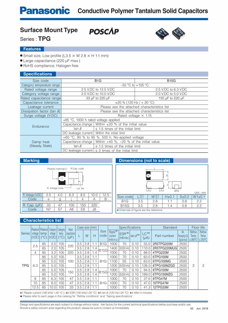
Series : TPG
● Small size, Low profi le (L3.5 × W 2.8 × H 1.1 mm)● Large capacitance (220 μF max.)● RoHS compliance, Halogen free
Features
Size code B1G B15GCategory temperature range –55 °C to +105 °C
Rated voltage range 2.5 V.DC to 12.5 V.DC 2.5 V.DC to 6.3 V.DC
Category voltage range 2.0 V.DC to 10.0 V.DC 2.0 V.DC to 5.0 V.DC
Rated capacitance range 33 μF to 220 μF 150 μF to 220 μF
Capacitance tolerance ±20 % (120 Hz / + 20 °C)
Leakage current Please see the attached characteristics list
Dissipation factor (tan d) Please see the attached characteristics list
Surge voltage (V.DC) Rated voltage × 1.15
Endurance
+85 °C, 1000 h rated voltage applied
Capacitance change Within ±20 % of the initial value
tan d < 1.5 times of the initial limit
DC leakage current Within the initial limit
Damp heat(Steady State)
+60 °C, 90 % to 95 %, 500 h, No-applied voltage
Capacitance change Within +40 %, −20 % of the initial value
tan d < 1.5 times of the initial limit
DC leakage current < 3 times of the initial limit
Size code L+0.3 W+0.3 H±0.1 S±0.2 W1±0.1
B1G 3.5 2.8 1.1 0.8 2.2
B15G 3.5 2.8 1.4 0.8 2.2
R. Voltage (V.DC) 2.5 4.0 6.3 8.0 10.0 12.5Code e g j k A B
R. Cap. (μF) 33 47 100 150 220Code N7 S7 A8 E8 J8
SeriesRatedvoltage(V.DC)
Ratedtemp.(°C)
Categoryvoltage
(V.DC)
Categorytemp.(°C)
Ratedcapacitance(μF)
Case size (mm)Size
code
Specifications Standard Floor life
L W HRipple ✽1 current(mAr.m.s.)
ESR ✽2
(mΩ max.)tan d ✽3 LC ✽4
(μA)Part number
Min. Packaging Q'ty(pcs)
Refl owTemp
< 260°C
Refl owTemp
< 250°C
TPG
2.585 2.0 105
2203.5 2.8 1.1 B1G 1000 70 0.10 55.0 2R5TPG220M 2500
3 3
85 2.0 105 3.5 2.8 1.4B15G
1400 30/300 kHz 0.10 110.0 2R5TPG220MUG 2500
4 85 3.2 105 220 3.5 2.8 1.4 1000 70 0.10 88.0 4TPG220M 2500
6.3
85 5.0 105
100
3.5 2.8 1.1
B1G
1000 70 0.10 63.0 6TPG100M 2500
85 5.0 105 3.5 2.8 1.1 1100 55 0.10 63.0 6TPG100MG 2500
85 5.0 105 3.5 2.8 1.1 1200 35/300 kHz 0.10 126.0 6TPG100MZGD 2500
85 5.0 105150
3.5 2.8 1.4B15G
1000 70 0.10 94.5 6TPG150M 2500
85 5.0 105 3.5 2.8 1.4 1200 35/300 kHz 0.10 189.0 6TPG150MZG 2500
8 85 6.3 105 47 3.5 2.8 1.1
B1G
1000 70 0.10 37.6 8TPG47M 2500
10 85 8.0 105 47 3.5 2.8 1.1 1000 70 0.10 47.0 10TPG47M 2500
12.5 85 10.0 105 33 3.5 2.8 1.1 1000 70 0.10 41.3 12TPG33M 2500
✽1 Ripple current (100 kHz/ +45 °C ), ✽2 ESR (100 kHz/+20 °C) ✽3 tan d (120 Hz/+20 °C) ✽4 After 5 minutes
◆ Please refer to each page in this catarog for “Reflow conditions” and “Taping specifications”.
Unit : mm
−0.1 −0.1
Marking
✽ Externals of fi gure are the reference.
Specifi cations
Dimensions (not to scale)
Characteristics list
Jun. 201802
Design and specifications are each subject to change without notice. Ask factory for the current technical specifications before purchase and/or use.
Should a safety concern arise regarding this product, please be sure to contact us immediately.
Conductive Polymer Tantalum Solid Capacitors
R.Cap. code Lot. No.
R. Voltage codePolarity marking(+)
W1
H
SS
L
W
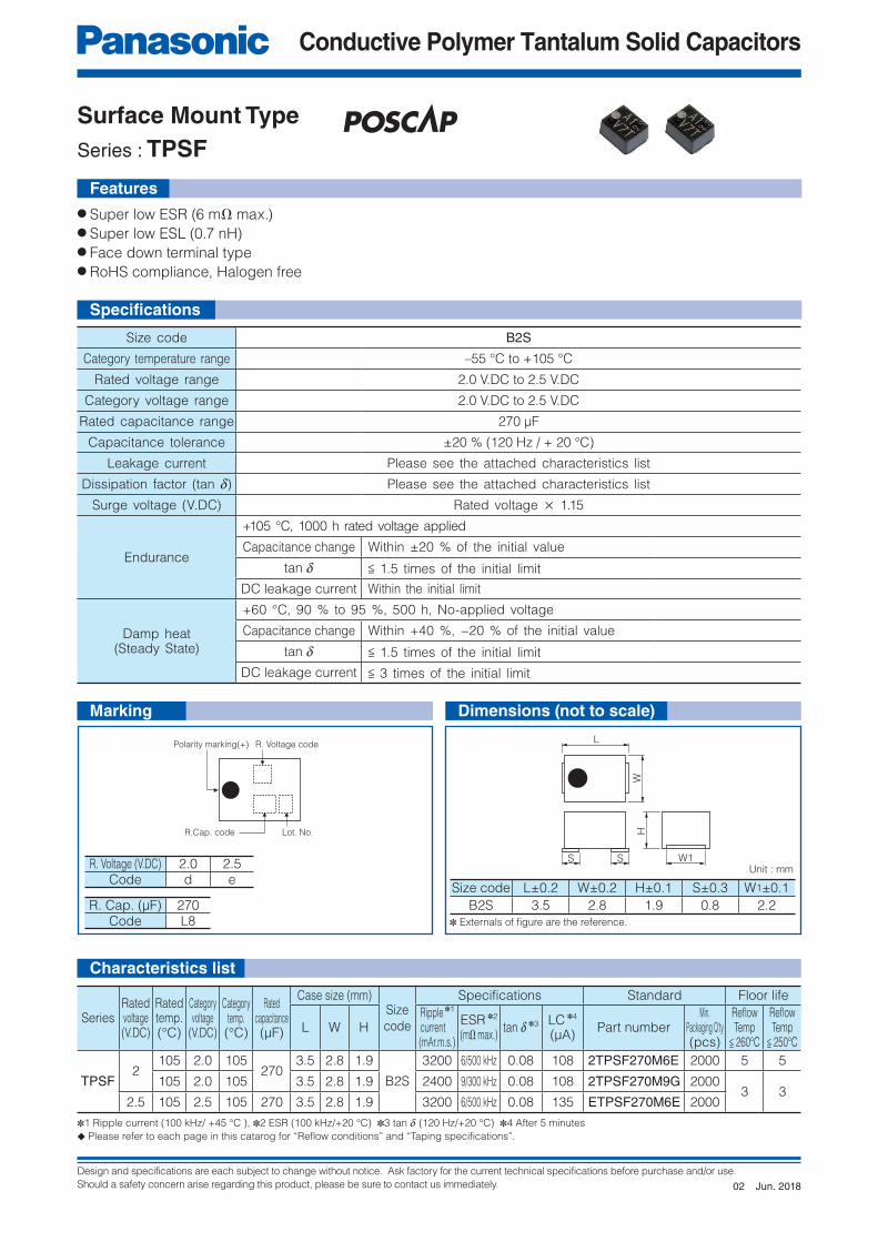
Surface Mount Type
Series : TPSF
● Super low ESR (6 mΩ max.)● Super low ESL (0.7 nH)● Face down terminal type● RoHS compliance, Halogen free
Size code B2S
Category temperature range –55 °C to +105 °C
Rated voltage range 2.0 V.DC to 2.5 V.DC
Category voltage range 2.0 V.DC to 2.5 V.DC
Rated capacitance range 270 μF
Capacitance tolerance ±20 % (120 Hz / + 20 °C)
Leakage current Please see the attached characteristics list
Dissipation factor (tan d) Please see the attached characteristics list
Surge voltage (V.DC) Rated voltage × 1.15
Endurance
+105 °C, 1000 h rated voltage applied
Capacitance change Within ±20 % of the initial value
tan d < 1.5 times of the initial limit
DC leakage current Within the initial limit
Damp heat(Steady State)
+60 °C, 90 % to 95 %, 500 h, No-applied voltage
Capacitance change Within +40 %, −20 % of the initial value
tan d < 1.5 times of the initial limit
DC leakage current < 3 times of the initial limit
SeriesRatedvoltage(V.DC)
Ratedtemp.(°C)
Categoryvoltage
(V.DC)
Categorytemp.(°C)
Ratedcapacitance(μF)
Case size (mm)Size
code
Specifications Standard Floor life
L W HRipple ✽1 current(mAr.m.s.)
ESR ✽2
(mΩ max.)tan d ✽3 LC ✽4
(μA)Part number
Min. Packaging Q'ty(pcs)
Refl owTemp
< 260°C
Refl owTemp
< 250°C
TPSF2
105 2.0 105270
3.5 2.8 1.9
B2S
3200 6/500 kHz 0.08 108 2TPSF270M6E 2000 5 5
105 2.0 105 3.5 2.8 1.9 2400 9/300 kHz 0.08 108 2TPSF270M9G 20003 3
2.5 105 2.5 105 270 3.5 2.8 1.9 3200 6/500 kHz 0.08 135 ETPSF270M6E 2000
Unit : mm
Marking
Size code L±0.2 W±0.2 H±0.1 S±0.3 W1±0.1
B2S 3.5 2.8 1.9 0.8 2.2
R. Voltage (V.DC) 2.0 2.5Code d e
R. Cap. (μF) 270Code L8 ✽ Externals of fi gure are the reference.
Dimensions (not to scale)
Characteristics list
Specifi cations
Features
✽1 Ripple current (100 kHz/ +45 °C ), ✽2 ESR (100 kHz/+20 °C) ✽3 tan d (120 Hz/+20 °C) ✽4 After 5 minutes
◆ Please refer to each page in this catarog for “Reflow conditions” and “Taping specifications”.
Jun. 201802

Design and specifications are each subject to change without notice. Ask factory for the current technical specifications before purchase and/or use.
Should a safety concern arise regarding this product, please be sure to contact us immediately.
Conductive Polymer Tantalum Solid Capacitors
Lot. No.
R.Cap. code
R. Voltage code
Polarity marking(+)
H
W1S S
L
W
● Small size (L 3.5×W 2.8×H 1.9 mm)● Low ESR (15 mΩ)● RoHS compliance, Halogen free
Surface Mount Type
Series : TPESize : B
Size code B2
Category temperature range –55 °C to +105 °C
Rated voltage range 2.0 V.DC to 10 V.DC
Category voltage range 1.8 V.DC to 8.0 V.DC
Rated capacitance range 47 μF to 470 μF
Capacitance tolerance ±20 % (120 Hz / + 20 °C)
Leakage current Please see the attached characteristics list
Dissipation factor (tan d) Please see the attached characteristics list
Surge voltage (V.DC) Rated voltage × 1.15
Endurance
+105 °C, 1000 h rated voltage applied
✽ Rated temp, +85 °C Products : +85 °C, 1000 h, rated voltage applied
Capacitance change Within ±20 % of the initial value
tan d < 1.5 times of the initial limit
DC leakage current Within the initial limit
Damp heat
(Steady State)
+60 °C, 90 % to 95 %, 500 h, No-applied voltage
Capacitance change
Within +50 %, −20 % of the initial value
(2R5TPE220MAZB (MAPB, MAFB), 2R5TPE330MAZB,
2TPE330MAFB (MADGB), 2TPE470MAJGB (MAFB), 2TPE330MFB,
ETPE330MAFB (MA9GB))
Within +40 %, −20 % of the initial value (Except for above model)
tan d < 1.5 times of the initial limit
DC leakage current < 3 times of the initial limit
Size code L±0.2 W±0.2 H±0.1 S±0.2 W1±0.1
B2 3.5 2.8 1.9 0.8 2.2
Unit : mm
Marking
R. Voltage (V.DC) 2.0 2.5 4.0 6.3 8.0 10.0
Code d e g j k A
R. Cap. (μF) 47 100 120 150 220 330 470
Code S7 A8 C8 E8 J8 N8 S8✽ Externals of fi gure are the reference.
Specifi cations
Features
Dimensions (not to scale)
Jun. 201805

Design and specifications are each subject to change without notice. Ask factory for the current technical specifications before purchase and/or use.
Should a safety concern arise regarding this product, please be sure to contact us immediately.
Conductive Polymer Tantalum Solid Capacitors
SeriesRatedvoltage(V.DC)
Ratedtemp.(°C)
Categoryvoltage
(V.DC)
Categorytemp.(°C)
Ratedcapacitance(μF)
Case size (mm)Sizecode
Specifications Standard Floor life
L W HRipple ✽1 current(mAr.m.s.)
ESR ✽2
(mΩ max.)tan d ✽3 LC ✽4
(μA)Part number
Min. Packaging Q'ty(pcs)
Refl owTemp
< 260°C
Refl owTemp
< 250°C
TPE
2
105 2.0 105
330
3.5 2.8 1.9
B2
2000 15 0.08 132.0 2TPE330MFB 2000
3 3
85 1.8 105 3.5 2.8 1.9 2000 15 0.08 132.0 2TPE330MAFB 2000
85 1.8 105 3.5 2.8 1.9 2000 13/300 kHz 0.10 132.0 2TPE330MADGB 2000
85 1.8 105470
3.5 2.8 1.9 2300 15 0.10 188.0 2TPE470MAFB 2000
85 1.8 105 3.5 2.8 1.9 2300 11/300 kHz 0.08 188.0 2TPE470MAJGB 2000
2.5
85 2.0 105
220
3.5 2.8 1.9 2000 15 0.08 110.0 2R5TPE220MAFB 2000
105 2.5 105 3.5 2.8 1.9 1800 15/300 kHz 0.08 110.0 2R5TPE220MFGB 2000
105 2.5 105 3.5 2.8 1.9 1700 21 0.08 55.0 2R5TPE220MLB 2000
85 2.0 105 3.5 2.8 1.9 1600 25 0.08 55.0 2R5TPE220MAPB 2000
105 2.5 105 3.5 2.8 1.9 1400 35 0.08 55.0 2R5TPE220MZB 2000
85 2.0 105 3.5 2.8 1.9 1400 35 0.08 55.0 2R5TPE220MAZB 2000
85 2.0 105
330
3.5 2.8 1.9 1400 35 0.08 82.5 2R5TPE330MAZB 2000
85 2.0 105 3.5 2.8 1.9 3200 9/300 kHz 0.08 165.0 ETPE330MA9GB 2000
105 2.0 105 3.5 2.8 1.9 3200 9/300 kHz 0.08 165.0 ETPE330M9GB 2000
85 2.0 105 3.5 2.8 1.9 2700 15 0.08 165.0 ETPE330MAFB 2000
105 2.0 105 3.5 2.8 1.9 2700 15 0.08 165.0 ETPE330MFB 2000
4
105 4.0 105 100 3.5 2.8 1.9 1400 35 0.08 40.0 4TPE100MZB 2000
85 3.2 105 150 3.5 2.8 1.9 1400 35 0.08 60.0 4TPE150MAZB 2000
85 3.2 105 220 3.5 2.8 1.9 1400 35 0.08 88.0 4TPE220MAZB 2000
6.3
105 6.3 105
100
3.5 2.8 1.9 1600 25 0.08 63.0 6TPE100MPB 2000
85 5.0 105 3.5 2.8 1.9 1400 35 0.08 63.0 6TPE100MAZB 2000
105 6.3 105 3.5 2.8 1.9 1400 35 0.08 63.0 6TPE100MZB 2000
85 5.0 105 120 3.5 2.8 1.9 1400 35 0.08 75.6 6TPE120MAZB 2000
85 5.0 105150
3.5 2.8 1.9 1600 25 0.08 94.5 6TPE150MAPB 2000
85 5.0 105 3.5 2.8 1.9 1400 35 0.08 94.5 6TPE150MAZB 2000
85 5.0 105220
3.5 2.8 1.9 1400 35 0.10 138.6 6TPE220MAZB 2000
85 5.0 105 3.5 2.8 1.9 1600 25 0.10 138.6 6TPE220MAPB 2000
8 85 6.3 105 100 3.5 2.8 1.9 1400 35 0.08 80.0 8TPE100MAZB 2000
10 85 8.0 105 47 3.5 2.8 1.9 1400 35 0.08 47.0 10TPE47MAZB 2000
✽1 Ripple current (100 kHz/ +45 °C ), ✽2 ESR (100 kHz/+20 °C) ✽3 tan d (120 Hz/+20 °C) ✽4 After 5 minutes
◆ Please refer to each page in this catarog for “Reflow conditions” and “Taping specifications”.
Characteristics list
NEW
NEW
NEW
NEW
Jun. 201805
Design and specifications are each subject to change without notice. Ask factory for the current technical specifications before purchase and/or use.
Should a safety concern arise regarding this product, please be sure to contact us immediately.
Conductive Polymer Tantalum Solid Capacitors
Lot. No.
R.Cap. code
R. Voltage code
Polarity marking(+)
H
W1S S
L
W
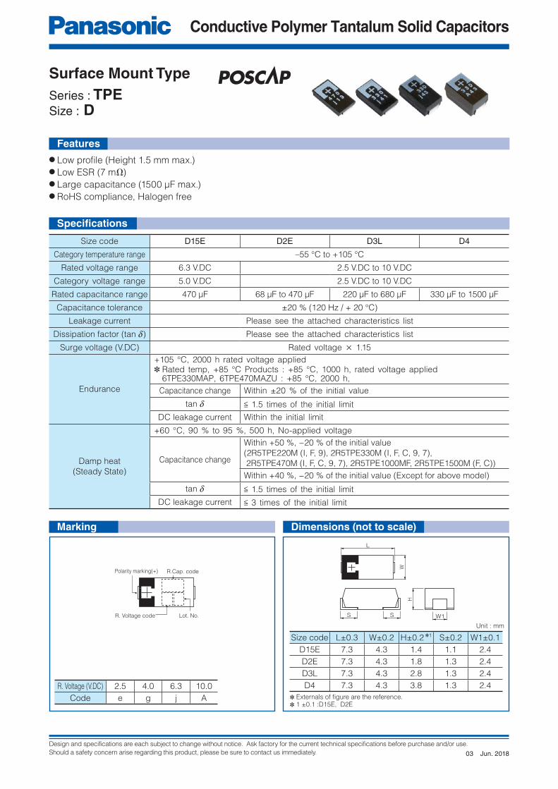
● Low profi le (Height 1.5 mm max.)● Low ESR (7 mΩ)● Large capacitance (1500 μF max.)● RoHS compliance, Halogen free
Surface Mount Type
Series : TPESize : D
Features
Size code D15E D2E D3L D4
Category temperature range –55 °C to +105 °C
Rated voltage range 6.3 V.DC 2.5 V.DC to 10 V.DC
Category voltage range 5.0 V.DC 2.5 V.DC to 10 V.DC
Rated capacitance range 470 μF 68 μF to 470 μF 220 μF to 680 μF 330 μF to 1500 μF
Capacitance tolerance ±20 % (120 Hz / + 20 °C)
Leakage current Please see the attached characteristics list
Dissipation factor (tan d) Please see the attached characteristics list
Surge voltage (V.DC) Rated voltage × 1.15
Endurance
+105 °C, 2000 h rated voltage applied✽ Rated temp, +85 °C Products : +85 °C, 1000 h, rated voltage applied 6TPE330MAP, 6TPE470MAZU : +85 °C, 2000 h,
Capacitance change Within ±20 % of the initial value
tan d < 1.5 times of the initial limit
DC leakage current Within the initial limit
Damp heat
(Steady State)
+60 °C, 90 % to 95 %, 500 h, No-applied voltage
Capacitance change
Within +50 %, −20 % of the initial value
(2R5TPE220M (I, F, 9), 2R5TPE330M (I, F, C, 9, 7),
2R5TPE470M (I, F, C, 9, 7), 2R5TPE1000MF, 2R5TPE1500M (F, C))
Within +40 %, −20 % of the initial value (Except for above model)
tan d < 1.5 times of the initial limit
DC leakage current < 3 times of the initial limit
Size code L±0.3 W±0.2 H±0.2 ✽1 S±0.2 W1±0.1
D15E 7.3 4.3 1.4 1.1 2.4
D2E 7.3 4.3 1.8 1.3 2.4
D3L 7.3 4.3 2.8 1.3 2.4
D4 7.3 4.3 3.8 1.3 2.4
Unit : mm
R. Voltage (V.DC) 2.5 4.0 6.3 10.0
Code e g j A ✽ Externals of fi gure are the reference.✽ 1 ±0.1 :D15E, D2E
Marking Dimensions (not to scale)
Specifi cations
Jun. 201803
Design and specifications are each subject to change without notice. Ask factory for the current technical specifications before purchase and/or use.
Should a safety concern arise regarding this product, please be sure to contact us immediately.
Conductive Polymer Tantalum Solid Capacitors
Characteristics list
SeriesRatedvoltage(V.DC)
Ratedtemp.(°C)
Categoryvoltage
(V.DC)
Categorytemp.(°C)
Ratedcapacitance(μF)
Case size (mm)Size
code
Specifications Standard Floor life
L W HRipple ✽1 current(mAr.m.s.)
ESR ✽2
(mΩ max.)tan d ✽3 LC ✽4
(μA)Part number
Min. Packaging Q'ty(pcs)
Refl owTemp
< 260°C
Refl owTemp
< 250°C
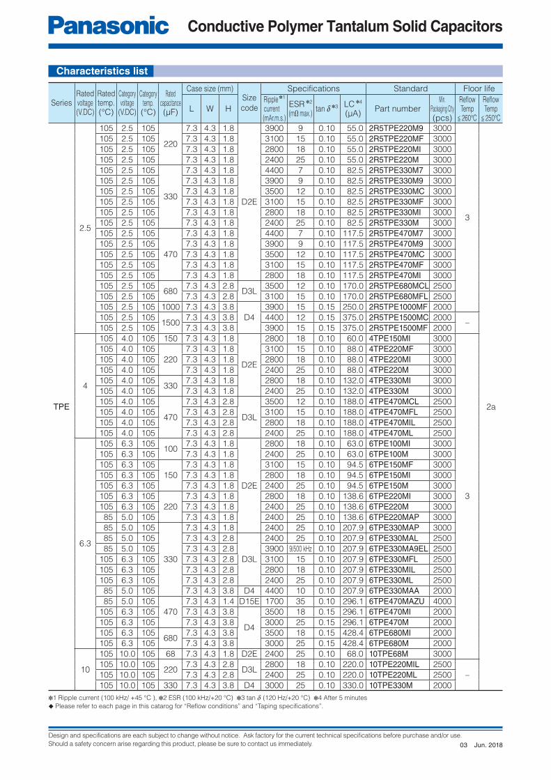
TPE
2.5
105 2.5 105
220
7.3 4.3 1.8
D2E
3900 9 0.10 55.0 2R5TPE220M9 3000
3
2a
105 2.5 105 7.3 4.3 1.8 3100 15 0.10 55.0 2R5TPE220MF 3000
105 2.5 105 7.3 4.3 1.8 2800 18 0.10 55.0 2R5TPE220MI 3000
105 2.5 105 7.3 4.3 1.8 2400 25 0.10 55.0 2R5TPE220M 3000
105 2.5 105
330
7.3 4.3 1.8 4400 7 0.10 82.5 2R5TPE330M7 3000
105 2.5 105 7.3 4.3 1.8 3900 9 0.10 82.5 2R5TPE330M9 3000
105 2.5 105 7.3 4.3 1.8 3500 12 0.10 82.5 2R5TPE330MC 3000
105 2.5 105 7.3 4.3 1.8 3100 15 0.10 82.5 2R5TPE330MF 3000
105 2.5 105 7.3 4.3 1.8 2800 18 0.10 82.5 2R5TPE330MI 3000
105 2.5 105 7.3 4.3 1.8 2400 25 0.10 82.5 2R5TPE330M 3000
105 2.5 105
470
7.3 4.3 1.8 4400 7 0.10 117.5 2R5TPE470M7 3000
105 2.5 105 7.3 4.3 1.8 3900 9 0.10 117.5 2R5TPE470M9 3000
105 2.5 105 7.3 4.3 1.8 3500 12 0.10 117.5 2R5TPE470MC 3000
105 2.5 105 7.3 4.3 1.8 3100 15 0.10 117.5 2R5TPE470MF 3000
105 2.5 105 7.3 4.3 1.8 2800 18 0.10 117.5 2R5TPE470MI 3000
105 2.5 105680
7.3 4.3 2.8D3L
3500 12 0.10 170.0 2R5TPE680MCL 2500
105 2.5 105 7.3 4.3 2.8 3100 15 0.10 170.0 2R5TPE680MFL 2500
105 2.5 105 1000 7.3 4.3 3.8
D4
3900 15 0.15 250.0 2R5TPE1000MF 2000
105 2.5 1051500
7.3 4.3 3.8 4400 12 0.15 375.0 2R5TPE1500MC 2000–
105 2.5 105 7.3 4.3 3.8 3900 15 0.15 375.0 2R5TPE1500MF 2000
4
105 4.0 105 150 7.3 4.3 1.8
D2E
2800 18 0.10 60.0 4TPE150MI 3000
3
105 4.0 105
220
7.3 4.3 1.8 3100 15 0.10 88.0 4TPE220MF 3000
105 4.0 105 7.3 4.3 1.8 2800 18 0.10 88.0 4TPE220MI 3000
105 4.0 105 7.3 4.3 1.8 2400 25 0.10 88.0 4TPE220M 3000
105 4.0 105330
7.3 4.3 1.8 2800 18 0.10 132.0 4TPE330MI 3000
105 4.0 105 7.3 4.3 1.8 2400 25 0.10 132.0 4TPE330M 3000
105 4.0 105
470
7.3 4.3 2.8
D3L
3500 12 0.10 188.0 4TPE470MCL 2500
105 4.0 105 7.3 4.3 2.8 3100 15 0.10 188.0 4TPE470MFL 2500
105 4.0 105 7.3 4.3 2.8 2800 18 0.10 188.0 4TPE470MIL 2500
105 4.0 105 7.3 4.3 2.8 2400 25 0.10 188.0 4TPE470ML 2500
6.3
105 6.3 105100
7.3 4.3 1.8
D2E
2800 18 0.10 63.0 6TPE100MI 3000
105 6.3 105 7.3 4.3 1.8 2400 25 0.10 63.0 6TPE100M 3000
105 6.3 105
150
7.3 4.3 1.8 3100 15 0.10 94.5 6TPE150MF 3000
105 6.3 105 7.3 4.3 1.8 2800 18 0.10 94.5 6TPE150MI 3000
105 6.3 105 7.3 4.3 1.8 2400 25 0.10 94.5 6TPE150M 3000
105 6.3 105
220
7.3 4.3 1.8 2800 18 0.10 138.6 6TPE220MI 3000
105 6.3 105 7.3 4.3 1.8 2400 25 0.10 138.6 6TPE220M 3000
85 5.0 105 7.3 4.3 1.8 2400 25 0.10 138.6 6TPE220MAP 3000
85 5.0 105
330
7.3 4.3 1.8 2400 25 0.10 207.9 6TPE330MAP 3000
85 5.0 105 7.3 4.3 2.8
D3L
2400 25 0.10 207.9 6TPE330MAL 2500
85 5.0 105 7.3 4.3 2.8 3900 9/500 kHz 0.10 207.9 6TPE330MA9EL 2500
105 6.3 105 7.3 4.3 2.8 3100 15 0.10 207.9 6TPE330MFL 2500
105 6.3 105 7.3 4.3 2.8 2800 18 0.10 207.9 6TPE330MIL 2500
105 6.3 105 7.3 4.3 2.8 2400 25 0.10 207.9 6TPE330ML 2500
85 5.0 105 7.3 4.3 3.8 D4 4400 10 0.10 207.9 6TPE330MAA 2000
85 5.0 105
470
7.3 4.3 1.4 D15E 1700 35 0.10 296.1 6TPE470MAZU 4000
105 6.3 105 7.3 4.3 3.8
D4
3500 18 0.15 296.1 6TPE470MI 2000
105 6.3 105 7.3 4.3 3.8 3000 25 0.15 296.1 6TPE470M 2000
105 6.3 105680
7.3 4.3 3.8 3500 18 0.15 428.4 6TPE680MI 2000
105 6.3 105 7.3 4.3 3.8 3000 25 0.15 428.4 6TPE680M 2000
10
105 10.0 105 68 7.3 4.3 1.8 D2E 2400 25 0.10 68.0 10TPE68M 3000
105 10.0 105220
7.3 4.3 2.8D3L
2800 18 0.10 220.0 10TPE220MIL 2500
–105 10.0 105 7.3 4.3 2.8 2400 25 0.10 220.0 10TPE220ML 2500
105 10.0 105 330 7.3 4.3 3.8 D4 3000 25 0.10 330.0 10TPE330M 2000
✽1 Ripple current (100 kHz/ +45 °C ), ✽2 ESR (100 kHz/+20 °C) ✽3 tan d (120 Hz/+20 °C) ✽4 After 5 minutes
◆ Please refer to each page in this catarog for “Reflow conditions” and “Taping specifications”.
Jun. 201803
Design and specifications are each subject to change without notice. Ask factory for the current technical specifications before purchase and/or use.
Should a safety concern arise regarding this product, please be sure to contact us immediately.
Conductive Polymer Tantalum Solid Capacitors
R.Cap. code
R. Voltage code Lot. No.
Polarity marking(+)
L
W
S W1
H
S
Surface Mount Type
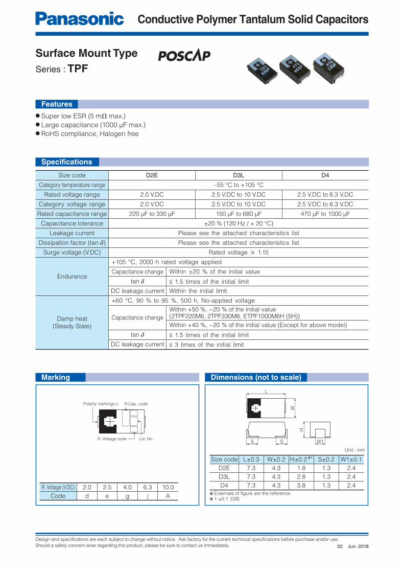
Series : TPF
● Super low ESR (5 mΩ max.)● Large capacitance (1000 μF max.)● RoHS compliance, Halogen free
Size code D2E D3L D4
Category temperature range –55 °C to +105 °C
Rated voltage range 2.0 V.DC 2.5 V.DC to 10 V.DC 2.5 V.DC to 6.3 V.DC
Category voltage range 2.0 V.DC 2.5 V.DC to 10 V.DC 2.5 V.DC to 6.3 V.DC
Rated capacitance range 220 μF to 330 μF 150 μF to 680 μF 470 μF to 1000 μF
Capacitance tolerance ±20 % (120 Hz / + 20 °C)
Leakage current Please see the attached characteristics list
Dissipation factor (tan d) Please see the attached characteristics list
Surge voltage (V.DC) Rated voltage × 1.15
Endurance
+105 °C, 2000 h rated voltage applied
Capacitance change Within ±20 % of the initial value
tan d < 1.5 times of the initial limit
DC leakage current Within the initial limit
Damp heat
(Steady State)
+60 °C, 90 % to 95 %, 500 h, No-applied voltage
Capacitance change
Within +50 %, −20 % of the initial value(2TPF220M6, 2TPF330M6, ETPF1000M6H (5H))
Within +40 %, −20 % of the initial value (Except for above model)
tan d < 1.5 times of the initial limit
DC leakage current < 3 times of the initial limit
Size code L±0.3 W±0.2 H±0.2 ✽1 S±0.2 W1±0.1
D2E 7.3 4.3 1.8 1.3 2.4
D3L 7.3 4.3 2.8 1.3 2.4
D4 7.3 4.3 3.8 1.3 2.4R. Voltage (V.DC) 2.0 2.5 4.0 6.3 10.0
Code d e g j A
Unit : mm
✽ Externals of fi gure are the reference.✽ 1 ±0.1 :D2E
Features
Specifi cations
Marking Dimensions (not to scale)
Jun. 201802
Design and specifications are each subject to change without notice. Ask factory for the current technical specifications before purchase and/or use.
Should a safety concern arise regarding this product, please be sure to contact us immediately.
Conductive Polymer Tantalum Solid Capacitors
Characteristics list
SeriesRatedvoltage(V.DC)
Ratedtemp.(°C)
Categoryvoltage
(V.DC)
Categorytemp.(°C)
Ratedcapacitance(μF)
Case size (mm)Size
code
Specifications Standard Floor life
L W HRipple ✽1 current(mAr.m.s.)
ESR ✽2
(mΩ max.)tan d ✽3 LC ✽4
(μA)Part number
Min. Packaging Q'ty(pcs)
Refl owTemp
< 260°C
Refl owTemp
< 250°C
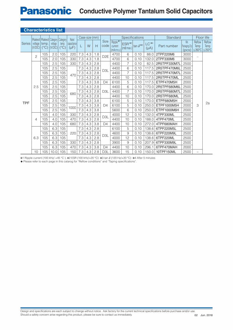
TPF
2105 2.0 105 220 7.3 4.3 1.8
D2E4700 6 0.10 88.0 2TPF220M6 3000
–
2a
105 2.0 105 330 7.3 4.3 1.8 4700 6 0.10 132.0 2TPF330M6 3000
2.5
105 2.5 105 330 7.3 4.3 2.8
D3L
4400 7 0.10 82.5 2R5TPF330M7L 2500
3
105 2.5 105
470
7.3 4.3 2.8 4400 6 0.10 117.5 2R5TPF470M6L 2500
105 2.5 105 7.3 4.3 2.8 4400 7 0.10 117.5 2R5TPF470M7L 2500
105 2.5 105 7.3 4.3 2.8 4400 10 0.10 117.5 2R5TPF470ML 2500
105 2.5 105 7.3 4.3 3.8 D4 6100 5 0.10 117.5 ETPF470M5H 2000
105 2.5 105
680
7.3 4.3 2.8
D3L
4400 6 0.10 170.0 2R5TPF680M6L 2500
105 2.5 105 7.3 4.3 2.8 4400 7 0.10 170.0 2R5TPF680M7L 2500
105 2.5 105 7.3 4.3 2.8 4400 10 0.10 170.0 2R5TPF680ML 2500
105 2.5 105 7.3 4.3 3.8
D4
6100 5 0.10 170.0 ETPF680M5H 2000
105 2.5 1051000
7.3 4.3 3.8 6100 5 0.10 250.0 ETPF1000M5H 2000
105 2.5 105 7.3 4.3 3.8 5600 6 0.10 250.0 ETPF1000M6H 2000
4
105 4.0 105 330 7.3 4.3 2.8D3L
4000 12 0.10 132.0 4TPF330ML 2500
105 4.0 105 470 7.3 4.3 2.8 4400 10 0.10 188.0 4TPF470ML 2500
105 4.0 105 680 7.3 4.3 3.8 D4 4400 10 0.10 272.0 4TPF680MAH 2000
6.3
105 6.3 105
220
7.3 4.3 2.8
D3L
6100 5 0.10 138.6 6TPF220M5L 2500
105 6.3 105 7.3 4.3 2.8 4600 9 0.10 138.6 6TPF220M9L 2500
105 6.3 105 7.3 4.3 2.8 4000 12 0.10 138.6 6TPF220ML 2500
105 6.3 105 330 7.3 4.3 2.8 3900 9 0.10 207.9 6TPF330M9L 2500
105 6.3 105 470 7.3 4.3 3.8 D4 4400 10 0.10 296.1 6TPF470MAH 2000
10 105 10.0 105 150 7.3 4.3 2.8 D3L 3600 15 0.10 150.0 10TPF150ML 2500 –
✽1 Ripple current (100 kHz/ +45 °C ), ✽2 ESR (100 kHz/+20 °C) ✽3 tan d (120 Hz/+20 °C) ✽4 After 5 minutes
◆ Please refer to each page in this catarog for “Reflow conditions” and “Taping specifications”.
Jun. 201802
Design and specifications are each subject to change without notice. Ask factory for the current technical specifications before purchase and/or use.
Should a safety concern arise regarding this product, please be sure to contact us immediately.
Conductive Polymer Tantalum Solid Capacitors
W1
H
SS
L
W
R.Cap. code Lot. No.
R. Voltage codePolarity marking(+)
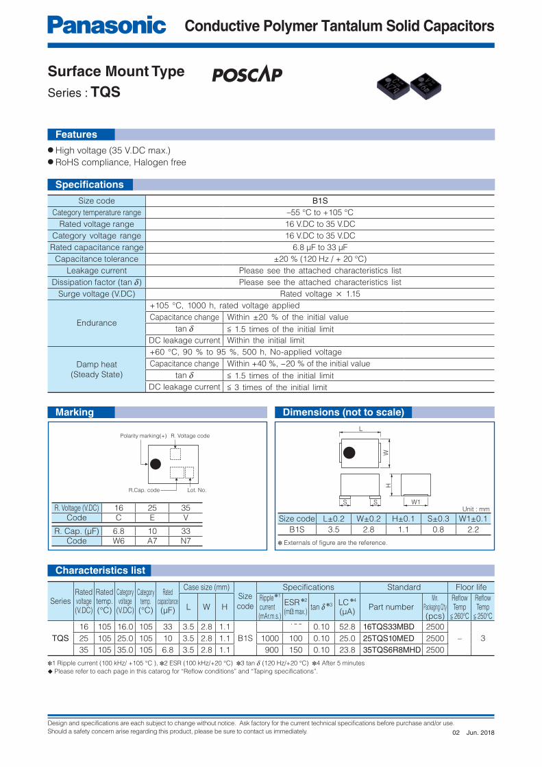
Surface Mount Type
Series : TQS
● High voltage (35 V.DC max.)● RoHS compliance, Halogen free
Features
Characteristics list
Size code B1SCategory temperature range –55 °C to +105 °C
Rated voltage range 16 V.DC to 35 V.DC
Category voltage range 16 V.DC to 35 V.DC
Rated capacitance range 6.8 μF to 33 μF
Capacitance tolerance ±20 % (120 Hz / + 20 °C)
Leakage current Please see the attached characteristics list
Dissipation factor (tan d) Please see the attached characteristics list
Surge voltage (V.DC) Rated voltage × 1.15
Endurance
+105 °C, 1000 h, rated voltage applied
Capacitance change Within ±20 % of the initial value
tan d < 1.5 times of the initial limit
DC leakage current Within the initial limit
Damp heat
(Steady State)
+60 °C, 90 % to 95 %, 500 h, No-applied voltage
Capacitance change Within +40 %, −20 % of the initial value
tan d < 1.5 times of the initial limit
DC leakage current < 3 times of the initial limit
Size code L±0.2 W±0.2 H±0.1 S±0.3 W1±0.1
B1S 3.5 2.8 1.1 0.8 2.2R. Cap. (μF) 6.8 10 33Code W6 A7 N7
R. Voltage (V.DC) 16 25 35Code C E V
SeriesRatedvoltage(V.DC)
Ratedtemp.(°C)
Categoryvoltage
(V.DC)
Categorytemp.(°C)
Ratedcapacitance(μF)
Case size (mm)Size
code
Specifications Standard Floor life
L W HRipple ✽1 current(mAr.m.s.)
ESR ✽2
(mΩ max.)tan d ✽3 LC ✽4
(μA)Part number
Min. Packaging Q'ty(pcs)
Refl owTemp
< 260°C
Refl owTemp
< 250°C
TQS16 105 16.0 105 33 3.5 2.8 1.1
B1S
1000 100 0.10 52.8 16TQS33MBD 2500
– 325 105 25.0 105 10 3.5 2.8 1.1 1000 100 0.10 25.0 25TQS10MED 2500
35 105 35.0 105 6.8 3.5 2.8 1.1 900 150 0.10 23.8 35TQS6R8MHD 2500
✽1 Ripple current (100 kHz/ +105 °C ), ✽2 ESR (100 kHz/+20 °C) ✽3 tan d (120 Hz/+20 °C) ✽4 After 5 minutes
◆ Please refer to each page in this catarog for “Reflow conditions” and “Taping specifications”.
Unit : mm
Marking Dimensions (not to scale)
✽ Externals of fi gure are the reference.
Specifi cations
Jun. 201802
Design and specifications are each subject to change without notice. Ask factory for the current technical specifications before purchase and/or use.
Should a safety concern arise regarding this product, please be sure to contact us immediately.
Conductive Polymer Tantalum Solid Capacitors
R.Cap. code
Lot. No.R. Voltage code
Polarity marking(+)
S W1
H
L
W
S
Surface Mount Type
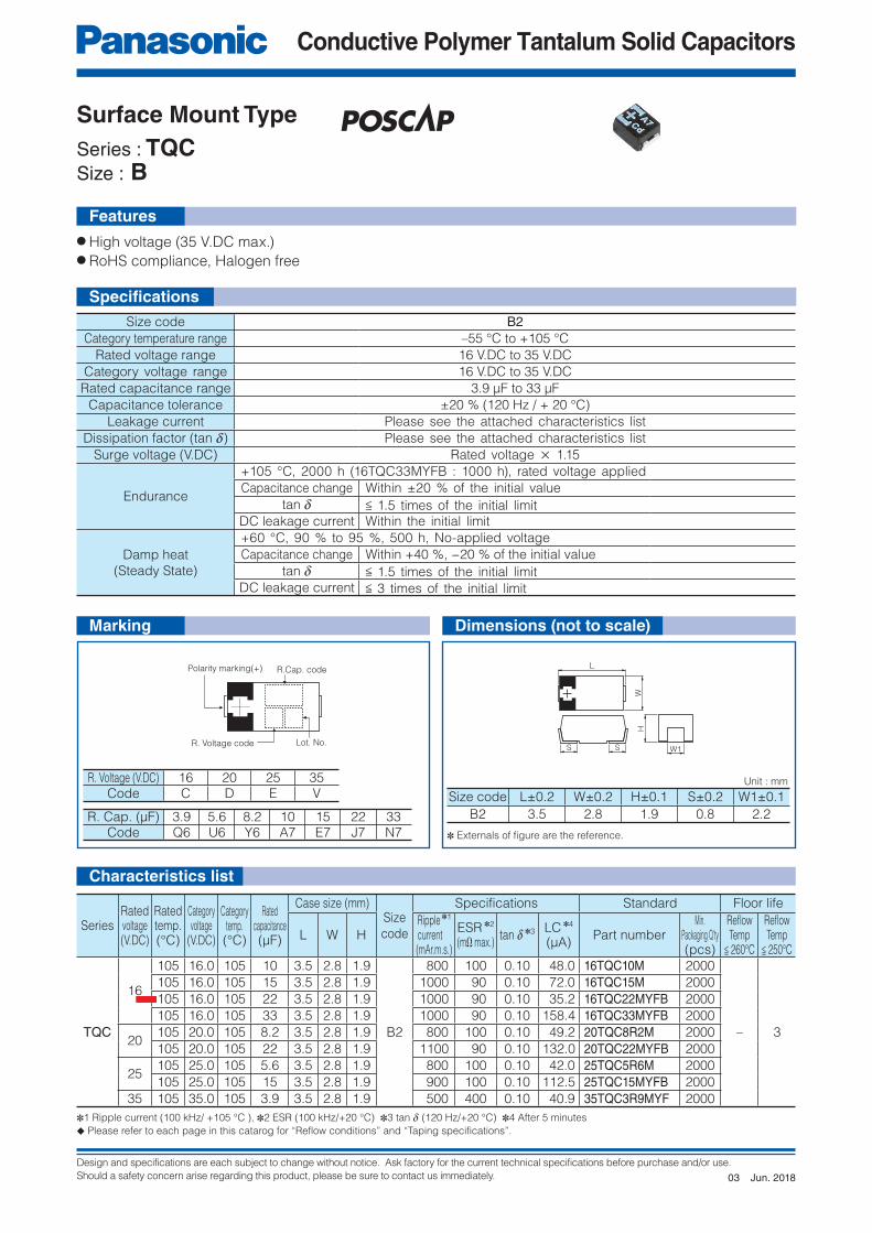
Series : TQCSize : B
● High voltage (35 V.DC max.)● RoHS compliance, Halogen free
Features
Characteristics list
Size code B2Category temperature range –55 °C to +105 °C
Rated voltage range 16 V.DC to 35 V.DC
Category voltage range 16 V.DC to 35 V.DC
Rated capacitance range 3.9 μF to 33 μF
Capacitance tolerance ±20 % (120 Hz / + 20 °C)
Leakage current Please see the attached characteristics list
Dissipation factor (tan d) Please see the attached characteristics list
Surge voltage (V.DC) Rated voltage × 1.15
Endurance
+105 °C, 2000 h (16TQC33MYFB : 1000 h), rated voltage applied
Capacitance change Within ±20 % of the initial value
tan d < 1.5 times of the initial limit
DC leakage current Within the initial limit
Damp heat
(Steady State)
+60 °C, 90 % to 95 %, 500 h, No-applied voltage
Capacitance change Within +40 %, −20 % of the initial value
tan d < 1.5 times of the initial limit
DC leakage current < 3 times of the initial limit
Size code L±0.2 W±0.2 H±0.1 S±0.2 W1±0.1
B2 3.5 2.8 1.9 0.8 2.2
R. Voltage (V.DC) 16 20 25 35Code C D E V
R. Cap. (μF) 3.9 5.6 8.2 10 15 22 33Code Q6 U6 Y6 A7 E7 J7 N7
SeriesRatedvoltage(V.DC)
Ratedtemp.(°C)
Categoryvoltage
(V.DC)
Categorytemp.(°C)
Ratedcapacitance(μF)
Case size (mm)Size
code
Specifications Standard Floor life
L W HRipple ✽1 current(mAr.m.s.)
ESR ✽2
(mΩ max.)tan d ✽3 LC ✽4
(μA)Part number
Min. Packaging Q'ty(pcs)
Refl owTemp
< 260°C
Refl owTemp
< 250°C
TQC
16
105 16.0 105 10 3.5 2.8 1.9
B2
800 100 0.10 48.0 16TQC10M 2000
– 3
105 16.0 105 15 3.5 2.8 1.9 1000 90 0.10 72.0 16TQC15M 2000
105 16.0 105 22 3.5 2.8 1.9 1000 90 0.10 35.2 16TQC22MYFB 2000
105 16.0 105 33 3.5 2.8 1.9 1000 90 0.10 158.4 16TQC33MYFB 2000
20105 20.0 105 8.2 3.5 2.8 1.9 800 100 0.10 49.2 20TQC8R2M 2000
105 20.0 105 22 3.5 2.8 1.9 1100 90 0.10 132.0 20TQC22MYFB 2000
25105 25.0 105 5.6 3.5 2.8 1.9 800 100 0.10 42.0 25TQC5R6M 2000
105 25.0 105 15 3.5 2.8 1.9 900 100 0.10 112.5 25TQC15MYFB 2000
35 105 35.0 105 3.9 3.5 2.8 1.9 500 400 0.10 40.9 35TQC3R9MYF 2000
✽1 Ripple current (100 kHz/ +105 °C ), ✽2 ESR (100 kHz/+20 °C) ✽3 tan d (120 Hz/+20 °C) ✽4 After 5 minutes
◆ Please refer to each page in this catarog for “Reflow conditions” and “Taping specifications”.
Unit : mm
Marking Dimensions (not to scale)
✽ Externals of fi gure are the reference.
Specifi cations
Jun. 201803

Design and specifications are each subject to change without notice. Ask factory for the current technical specifications before purchase and/or use.
Should a safety concern arise regarding this product, please be sure to contact us immediately.
Conductive Polymer Tantalum Solid Capacitors
R.Cap. code
Lot. No.R. Voltage code
Polarity marking(+)
S W1
H
L
W
S
Surface Mount Type
Series : TQCSize : D
● High voltage (35 V.DC max.)● RoHS compliance, Halogen free
Size code D12 D15 D2 D3LCategory temperature range –55 °C to +105 °C
Rated voltage range 16 V.DC 16 V.DC to 25 V.DC 16 V.DC to 35 V.DC 16 V.DC to 25 V.DC
Category voltage range 16 V.DC 16 V.DC to 25 V.DC 16 V.DC to 35 V.DC 16 V.DC to 25 V.DC
Rated capacitance range 33 µF 22 µF to 47 µF 10 µF to 100 µF 68 µF to 150 µF
Capacitance tolerance ±20 % (120 Hz / + 20 °C)
Leakage current Please see the attached characteristics list
Dissipation factor (tan d) Please see the attached characteristics list
Surge voltage (V.DC) Rated voltage × 1.15
Endurance
+105 °C, 2000 h, rated voltage appliedCapacitance change Within ±20 % of the initial value
tan d < 1.5 times of the initial limitDC leakage current Within the initial limit
Damp heat
(Steady State)
+60 °C, 90 % to 95 %, 500 h, No-applied voltageCapacitance change Within +40 %, −20 % of the initial value
tan d < 1.5 times of the initial limitDC leakage current < 3 times of the initial limit
R. Voltage (V.DC) 16 20 25 35
Code C D 1E V
SeriesRatedvoltage(V.DC)
Ratedtemp.(°C)
Categoryvoltage
(V.DC)
Categorytemp.(°C)
Ratedcapacitance(µF)
Case size (mm)Sizecode
Specifications Standard Floor life
L W HRipple ✽1 current(mAr.m.s.)
ESR ✽2
(mΩ max.)tan d ✽3 LC ✽4
(µA)Part number
Min. Packaging Q'ty(pcs)
Refl owTemp
< 260°C
Refl owTemp
< 250°C
TQC
16
105 16.0 105 33
7.3 4.3 1.15 D12 1800 40 0.10 52.8 16TQC33MYFS 4500
– 3
105 16.0 105 7.3 4.3 1.9 D2 1400 70 0.10 52.8 16TQC33MYFD 3000105 16.0 105
477.3 4.3 1.4 D15 1500 55 0.10 75.2 16TQC47MYFT 3000
105 16.0 105 7.3 4.3 1.9
D2
1800 40 0.10 75.2 16TQC47MW 3000105 16.0 105 7.3 4.3 1.9 1450 55 0.10 75.2 16TQC47MYFD 3000105 16.0 105 68 7.3 4.3 1.9 1500 50 0.10 108.8 16TQC68MYF 3000105 16.0 105 100 7.3 4.3 1.9 1800 50 0.10 160.0 16TQC100MYF 3000105 16.0 105 150 7.3 4.3 2.8 D3L 1800 50 0.10 240.0 16TQC150MYF 2500105 16.0 105 150 7.3 4.3 1.9
D21500 70 0.15 240.0 1CTQC15173F1 3000
20
105 20.0 105 33 7.3 4.3 1.9 1400 60 0.10 66.0 20TQC33MYFD 3000105 20.0 105
477.3 4.3 1.9 1450 55 0.10 94.0 20TQC47MYF 3000
105 20.0 105 7.3 4.3 1.4 D15 1500 55 0.10 94.0 20TQC47MYFT 3000105 20.0 105
1007.3 4.3 1.9 D2 1250 100 0.15 200.0 20TQC100MD2 3000
105 20.0 105 7.3 4.3 2.8 D3L 1700 55 0.10 200.0 20TQC100MYF 2500
25
105 25.0 105 15
7.3 4.3 1.9
D2
1500 45 0.10 38.0 25TQC15MV 3000105 25.0 105 7.3 4.3 1.9 1000 90 0.10 38.0 25TQC15MYFD 3000105 25.0 105
227.3 4.3 1.9 1500 45 0.10 55.0 25TQC22MV 3000
105 25.0 105 7.3 4.3 1.9 1400 60 0.10 55.0 25TQC22MYFD 3000105 25.0 105 7.3 4.3 1.4 D15 1400 70 0.10 55.0 25TQC22MYFT 3000105 25.0 105 33 7.3 4.3 1.9 D2 1400 60 0.10 82.5 25TQC33MYF 3000105 25.0 105 68 7.3 4.3 2.8 D3L 1400 70 0.10 170.0 25TQC68MYF 2500
35105 35.0 105
107.3 4.3 1.9
D21000 120 0.10 35.0 35TQC10M 3000
105 35.0 105 7.3 4.3 1.9 1000 120 0.10 35.0 35TQC10MYF 3000105 35.0 105 15 7.3 4.3 1.9 900 150 0.10 52.5 35TQC15MYF 3000
✽1 Ripple current (100 kHz/ +105 °C ), ✽2 ESR (100 kHz/+20 °C) ✽3 tan d (120 Hz/+20 °C) ✽4 After 5 minutes◆ Please refer to each page in this catarog for “Reflow conditions” and “Taping specifications”.
Unit : mm
✽ Externals of fi gure are the reference.✽ 1 ±0.3 : D3L✽ 2 ±0.05 : D12, ±0.2 : D3L
Features
Specifi cations
Characteristics list
Marking Dimensions (not to scale)
Size code
L±0.2 W±0.2 H±0.1 S±0.2 W1±0.1
D12 7.3 4.3 1.15 1.3 2.4
D15 7.3 4.3 1.4 1.3 2.4
D2 7.3 4.3 1.9 1.3 2.4
D3L 7.3 4.3 2.8 1.3 2.4
✽1 ✽2
Jun. 201803

Design and specifications are each subject to change without notice. Ask factory for the current technical specifications before purchase and/or use.
Should a safety concern arise regarding this product, please be sure to contact us immediately.
Conductive Polymer Tantalum Solid Capacitors
R.Cap. code
R. Voltage code Lot. No.
Polarity
marking(+) R.Cap. code
Polarity
marking(+)
Lot. No.R. Voltage code
L
W
S W1
H
S
● Guaranteed at 85 °C 85 %RH ● RoHS compliance, Halogen free
◆ This product is not intended for use in any driving application or any other critical functions that affect passenger safety. (e.g. Powertrain, ABS, Engine ECU, Airbag, etc.) If the intended use of TA/TV series products is for use in other automotive related applications, please contact our sales team. All requests are subject to approval.
Features
Surface Mount Type
Series : TA
Size code B2 D2E D3LCategory temperature range –55 °C to +105 °C
Rated voltage range 4 V.DC to 10 V.DC 2.5 V.DC to 10 V.DCCategory voltage range 4 V.DC to 10 V.DC 2.5 V.DC to 10 V.DC
Rated capacitance range 47μF to 100 μF 68 μF to 470 μF 150 μF to 680 μFCapacitance tolerance ±20 % (120 Hz / + 20 °C)
Leakage current Please see the attached characteristics listDissipation factor (tan d) Please see the attached characteristics list
Surge voltage (V.DC) Rated voltage × 1.15
Endurance
+105 °C, 2000 h, (B2 size : 1000 h) rated voltage appliedCapacitance change Within ±20 % of the initial value
tan d < 1.5 times of the initial limitDC leakage current Within the initial limit
Damp heat(Steady State)
+85 °C, 85 % to 90 %, 500 h, rated voltage applied
Capacitance changeWithin +50 %, −20 % of the initial value (2R5TAE470M(F), 2R5TAE330M(F, I), 2R5TAE220M(F, 9))Within +40 %, −20 % of the initial value (Except for above model)
tan d < 1.5 times of the initial limitDC leakage current Within the initial limit
SeriesRatedvoltage(V.DC)
Ratedtemp.(°C)
Categoryvoltage(V.DC)
Categorytemp.(°C)
Ratedcapacitance(μF)
Case size (mm)Sizecode
Specifications Standard Floor life
L W HRipple ✽1 current(mAr.m.s.)
ESR ✽2
(mΩ max.)tan d ✽3 LC ✽4
(μA)Part number
Min. Packaging Q'ty
(pcs)
Refl owTemp
< 260°C
Refl owTemp
< 250°C
TA
2.5
105 2.5 105220
7.3 4.3 1.8
D2E
3900 9 0.10 110.0 2R5TAE220M9 3000
3 3
105 2.5 105 7.3 4.3 1.8 3100 15 0.10 55.0 2R5TAE220MF 3000105 2.5 105 7.3 4.3 1.8 2400 25 0.10 55.0 2R5TAE220M 3000105 2.5 105
3307.3 4.3 1.8 3100 15 0.10 82.5 2R5TAE330MF 3000
105 2.5 105 7.3 4.3 1.8 2800 18 0.10 82.5 2R5TAE330MI 3000105 2.5 105 7.3 4.3 1.8 2400 25 0.10 82.5 2R5TAE330M 3000105 2.5 105
4707.3 4.3 1.8 3100 15 0.10 117.5 2R5TAE470MF 3000
105 2.5 105 7.3 4.3 1.8 2400 25 0.10 117.5 2R5TAE470M 3000105 2.5 105
6807.3 4.3 2.8
D3L3100 15 0.10 170.0 2R5TAE680MFL 2500
105 2.5 105 7.3 4.3 2.8 2400 25 0.10 170.0 2R5TAE680ML 2500
4
105 4.0 105 100 3.8 2.8 1.9 B2 1100 70 0.08 40.0 4TAB100M 2000105 4.0 105
2207.3 4.3 1.8
D2E2800 18 0.10 88.0 4TAE220MI 3000
105 4.0 105 7.3 4.3 1.8 2400 25 0.10 88.0 4TAE220M 3000105 4.0 105
4707.3 4.3 2.8
D3L2800 18 0.10 188.0 4TAE470MIL 2500
105 4.0 105 7.3 4.3 2.8 2400 25 0.10 188.0 4TAE470ML 2500
6.3
105 6.3 105 47 3.5 2.8 1.9B2
1100 70 0.08 29.6 6TAB47M 2000105 6.3 105 68 3.5 2.8 1.9 1100 70 0.08 42.8 6TAB68M 2000105 6.3 105 150 7.3 4.3 1.8
D2E2400 25 0.10 94.5 6TAE150M 3000
105 6.3 105220
7.3 4.3 1.8 2800 18 0.10 138.6 6TAE220MI 3000105 6.3 105 7.3 4.3 1.8 2400 25 0.10 138.6 6TAE220M 3000105 6.3 105 330 7.3 4.3 2.8 D3L 2400 25 0.10 207.9 6TAE330ML 2500
10
105 10.0 105 47 3.5 2.8 1.9 B2 1100 70 0.08 47.0 10TAB47M 2000105 10.0 105 68 7.3 4.3 1.8 D2E 2400 25 0.10 68.0 10TAE68M 3000105 10.0 105 150 7.3 4.3 2.8
D3L2400 25 0.10 150.0 10TAE150ML 2500
105 10.0 105 220 7.3 4.3 2.8 2400 25 0.10 220.0 10TAE220ML 2500
✽1 Ripple current (100 kHz/ +45 °C ), ✽2 ESR (100 kHz/+20 °C) ✽3 tan d (120 Hz/+20 °C) ✽4 After 5 minutes
◆ Please refer to each page in this catarog for “Reflow conditions” and “Taping specifications”.
SizeCode
L±0.3✽1
W±0.2 H±0.2✽2
S±0.2 W1±0.1
B2 3.5 2.8 1.9 0.8 2.2D2E 7.3 4.3 1.8 1.3 2.4D3L 7.3 4.3 2.8 1.3 2.4
R. Voltage (V.DC)
2.5 4.0 6.3 10.0
Code e g j A
R. Cap. (μF)
47 68 100
Code S7 W7 A8
Unit : mm
✽ Externals of fi gure are the reference.
✽ 1 ±0.2 : B2✽ 2 ±0.1 : B2, D2E
B2 Size
D2E, D3L Size B2 Size
Marking Dimensions (not to scale)
Characteristics list
Specifi cations
Jun. 201803
Design and specifications are each subject to change without notice. Ask factory for the current technical specifications before purchase and/or use.
Should a safety concern arise regarding this product, please be sure to contact us immediately.
Conductive Polymer Tantalum Solid Capacitors
R.Cap. code
R. Voltage code Lot. No.
Polarity
marking(+)
L
W
S W1
H
S
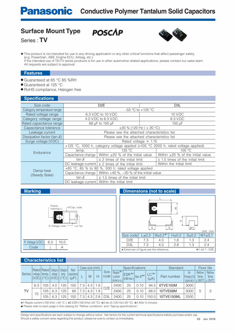
Surface Mount Type
Series : TV
● Guaranteed at 85 °C 85 %RH● Guaranteed at 125 °C● RoHS compliance, Halogen free
◆ This product is not intended for use in any driving application or any other critical functions that affect passenger safety. (e.g. Powertrain, ABS, Engine ECU, Airbag, etc.) If the intended use of TA/TV series products is for use in other automotive related applications, please contact our sales team. All requests are subject to approval.
Specifi cations
Features
Characteristics list
Size code D2E D3LCategory temperature range –55 °C to +125 °C
Rated voltage range 6.3 V.DC to 10 V.DC 10 V.DC
Category voltage range 4.0 V.DC to 6.3 V.DC 6.3 V.DC
Rated capacitance range 68 µF to 150 µF 150 µF
Capacitance tolerance ±20 % (120 Hz / + 20 °C)
Leakage current Please see the attached characteristics list
Dissipation factor (tan d) Please see the attached characteristics list
Surge voltage (V.DC) Rated voltage × 1.15
Endurance
+125 °C, 1000 h, category voltage applied (+105 °C 2000 h, rated voltage applied)
temp. 125 °C 105 °C
Capacitance change Within ±20 % of the initial value Within ±20 % of the initial value
tan d < 2 times of the initial limit < 1.5 times of the initial limit
Damp heat
(Steady State)
DC leakage current < 2 times of the initial limit Within the initial limit
+85 °C, 85 % to 90 %, 500 h, rated voltage applied
Capacitance change Within +40 %, −20 % of the initial value
tan d < 1.5 times of the initial limit
DC leakage current Within the initial limit
Size code L±0.3 W±0.2 ✽1 H±0.2 S±0.2 W1±0.1
D2E 7.3 4.3 1.8 1.3 2.4
D3L 7.3 4.3 2.8 1.3 2.4R. Voltage (V.DC) 6.3 10.0
Code j A
SeriesRatedvoltage(V.DC)
Ratedtemp.(°C)
Categoryvoltage
(V.DC)
Categorytemp.(°C)
Ratedcapacitance(µF)
Case size (mm)Size
code
Specifications Standard Floor life
L W HRipple ✽1 current(mAr.m.s.)
ESR ✽2
(mΩ max.)tan d ✽3 LC ✽4
(µA)Part number
Min. Packaging Q'ty(pcs)
Refl owTemp
< 260°C
Refl owTemp
< 250°C
TV
6.3 105 4.0 125 150 7.3 4.3 1.8D2E
2400 25 0.10 94.5 6TVE150M 3000
5 310
105 6.3 125 68 7.3 4.3 1.8 2400 25 0.10 68.0 10TVE68M 3000
105 6.3 125 150 7.3 4.3 2.8 D3L 2400 25 0.10 150.0 10TVE150ML 2500
✽1 Ripple current (100 kHz/ +45 °C ), ✽2 ESR (100 kHz/+20 °C) ✽3 tan d (120 Hz/+20 °C) ✽4 After 5 minutes
◆ Please refer to each page in this catarog for “Reflow conditions” and “Taping specifications”.
Unit : mm
✽1 ±0.1 : D2E✽ Externals of fi gure are the reference.
Marking Dimensions (not to scale)
Jun. 201803
Design and specifications are each subject to change without notice. Ask factory for the current technical specifications before purchase and/or use.
Should a safety concern arise regarding this product, please be sure to contact us immediately.
Conductive Polymer Tantalum Solid Capacitors
S W1
H
L
W
S
R. Voltage code Lot. No.
R.Cap. codePolarity marking(+)
R. Voltage code Lot. No.
R.Cap. codePolarity marking(+)
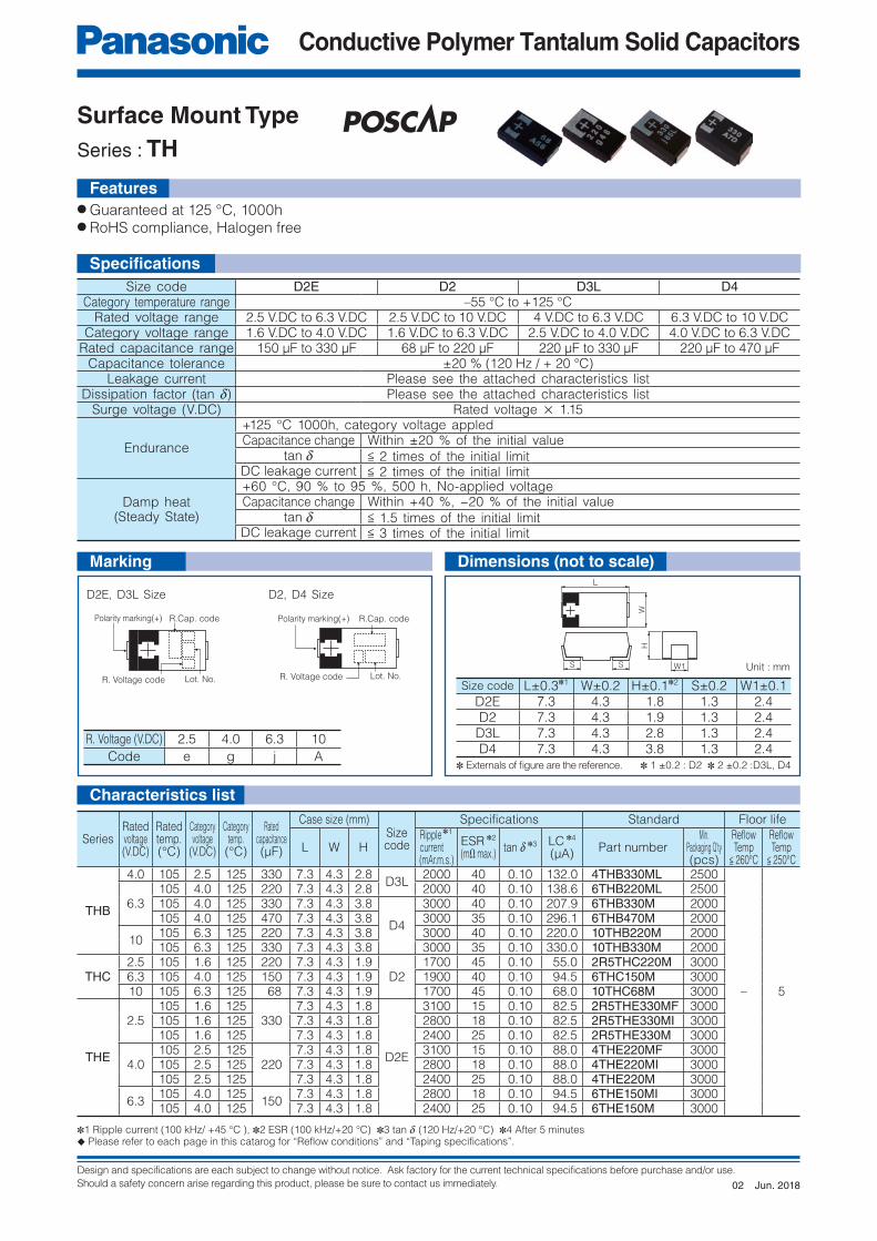
Surface Mount Type
Series : TH
● Guaranteed at 125 °C, 1000h● RoHS compliance, Halogen free
Size code D2E D2 D3L D4Category temperature range –55 °C to +125 °C
Rated voltage range 2.5 V.DC to 6.3 V.DC 2.5 V.DC to 10 V.DC 4 V.DC to 6.3 V.DC 6.3 V.DC to 10 V.DCCategory voltage range 1.6 V.DC to 4.0 V.DC 1.6 V.DC to 6.3 V.DC 2.5 V.DC to 4.0 V.DC 4.0 V.DC to 6.3 V.DC
Rated capacitance range 150 µF to 330 µF 68 µF to 220 µF 220 µF to 330 µF 220 µF to 470 µFCapacitance tolerance ±20 % (120 Hz / + 20 °C)
Leakage current Please see the attached characteristics listDissipation factor (tan d) Please see the attached characteristics list
Surge voltage (V.DC) Rated voltage × 1.15
Endurance
+125 °C 1000h, category voltage appledCapacitance change Within ±20 % of the initial value
tan d < 2 times of the initial limitDC leakage current < 2 times of the initial limit
Damp heat(Steady State)
+60 °C, 90 % to 95 %, 500 h, No-applied voltageCapacitance change Within +40 %, −20 % of the initial value
tan d < 1.5 times of the initial limitDC leakage current < 3 times of the initial limit
Size code L±0.3✽1 W±0.2 H±0.1✽2 S±0.2 W1±0.1D2E 7.3 4.3 1.8 1.3 2.4D2 7.3 4.3 1.9 1.3 2.4
D3L 7.3 4.3 2.8 1.3 2.4D4 7.3 4.3 3.8 1.3 2.4
R. Voltage (V.DC) 2.5 4.0 6.3 10
Code e g j A
SeriesRatedvoltage(V.DC)
Ratedtemp.(°C)
Categoryvoltage
(V.DC)
Categorytemp.(°C)
Ratedcapacitance(µF)
Case size (mm)Sizecode
Specifications Standard Floor life
L W HRipple ✽1 current(mAr.m.s.)
ESR ✽2
(mΩ max.)tan d ✽3 LC ✽4
(µA)Part number
Min. Packaging Q'ty(pcs)
Refl owTemp
< 260°C
Refl owTemp
< 250°C
THB
4.0 105 2.5 125 330 7.3 4.3 2.8D3L
2000 40 0.10 132.0 4THB330ML 2500
– 5
6.3105 4.0 125 220 7.3 4.3 2.8 2000 40 0.10 138.6 6THB220ML 2500105 4.0 125 330 7.3 4.3 3.8
D4
3000 40 0.10 207.9 6THB330M 2000105 4.0 125 470 7.3 4.3 3.8 3000 35 0.10 296.1 6THB470M 2000
10105 6.3 125 220 7.3 4.3 3.8 3000 40 0.10 220.0 10THB220M 2000105 6.3 125 330 7.3 4.3 3.8 3000 35 0.10 330.0 10THB330M 2000
THC2.5 105 1.6 125 220 7.3 4.3 1.9
D21700 45 0.10 55.0 2R5THC220M 3000
6.3 105 4.0 125 150 7.3 4.3 1.9 1900 40 0.10 94.5 6THC150M 300010 105 6.3 125 68 7.3 4.3 1.9 1700 45 0.10 68.0 10THC68M 3000
THE
2.5105 1.6 125
3307.3 4.3 1.8
D2E
3100 15 0.10 82.5 2R5THE330MF 3000105 1.6 125 7.3 4.3 1.8 2800 18 0.10 82.5 2R5THE330MI 3000105 1.6 125 7.3 4.3 1.8 2400 25 0.10 82.5 2R5THE330M 3000
4.0105 2.5 125
2207.3 4.3 1.8 3100 15 0.10 88.0 4THE220MF 3000
105 2.5 125 7.3 4.3 1.8 2800 18 0.10 88.0 4THE220MI 3000105 2.5 125 7.3 4.3 1.8 2400 25 0.10 88.0 4THE220M 3000
6.3105 4.0 125
1507.3 4.3 1.8 2800 18 0.10 94.5 6THE150MI 3000
105 4.0 125 7.3 4.3 1.8 2400 25 0.10 94.5 6THE150M 3000
✽1 Ripple current (100 kHz/ +45 °C ), ✽2 ESR (100 kHz/+20 °C) ✽3 tan d (120 Hz/+20 °C) ✽4 After 5 minutes◆ Please refer to each page in this catarog for “Reflow conditions” and “Taping specifications”.
Unit : mm
Marking
✽ Externals of fi gure are the reference. ✽ 1 ±0.2 : D2 ✽ 2 ±0.2 :D3L, D4
D2E, D3L Size D2, D4 Size
Features
Specifi cations
Dimensions (not to scale)
Characteristics list
Jun. 201802
Design and specifications are each subject to change without notice. Ask factory for the current technical specifications before purchase and/or use.
Should a safety concern arise regarding this product, please be sure to contact us immediately.
Conductive Polymer Tantalum Solid Capacitors
R.Cap. code
R. Voltage code Lot. No.
Polarity marking(+)
R. Voltage code Lot. No.
R.Cap. codePolarity marking(+)
R. Voltage code Lot. No.
R.Cap. codePolarity marking(+)
L
S S W1
WH
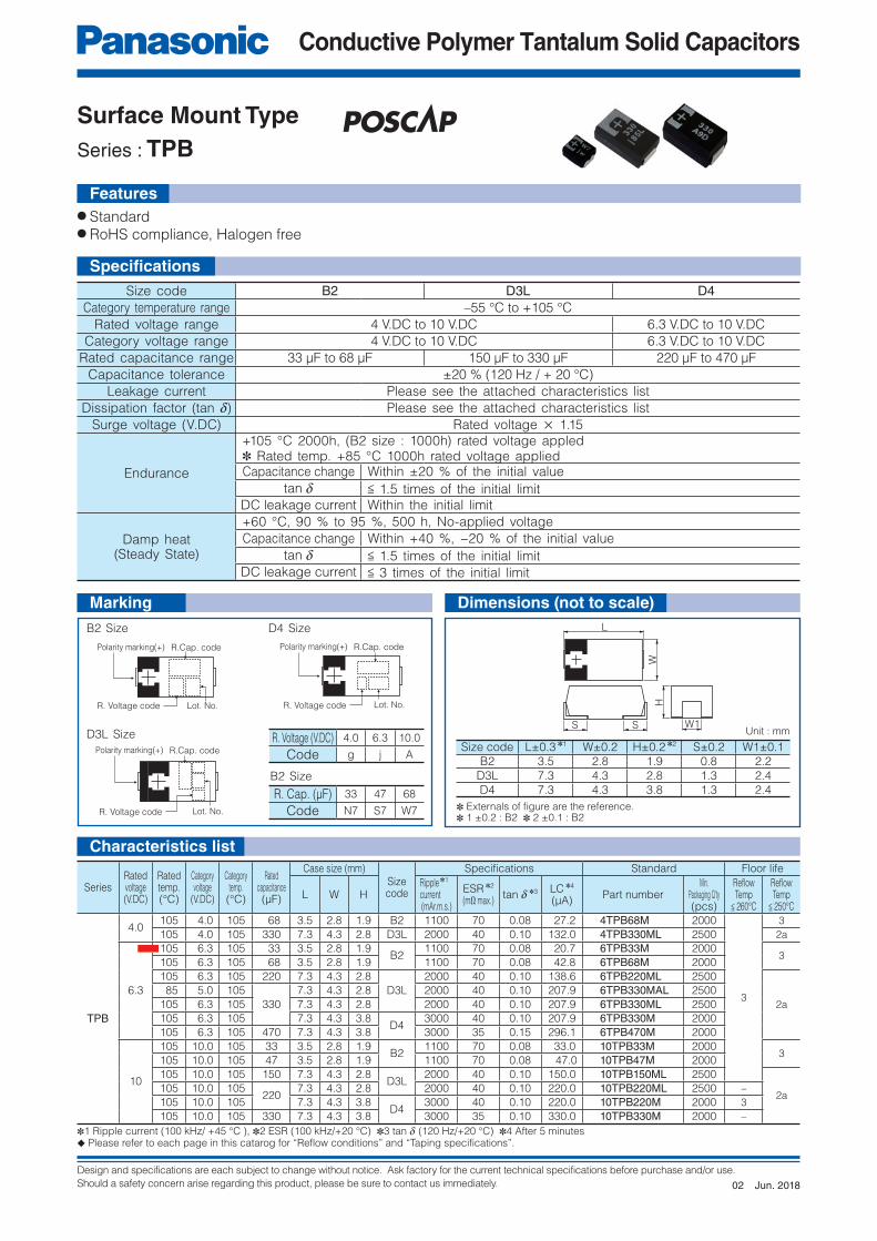
Surface Mount Type
Series : TPB
● Standard● RoHS compliance, Halogen free
Size code B2 D3L D4Category temperature range –55 °C to +105 °C
Rated voltage range 4 V.DC to 10 V.DC 6.3 V.DC to 10 V.DC
Category voltage range 4 V.DC to 10 V.DC 6.3 V.DC to 10 V.DC
Rated capacitance range 33 μF to 68 μF 150 μF to 330 μF 220 μF to 470 μF
Capacitance tolerance ±20 % (120 Hz / + 20 °C)
Leakage current Please see the attached characteristics list
Dissipation factor (tan d) Please see the attached characteristics list
Surge voltage (V.DC) Rated voltage × 1.15
Endurance
+105 °C 2000h, (B2 size : 1000h) rated voltage appled ✽ Rated temp. +85 °C 1000h rated voltage appliedCapacitance change Within ±20 % of the initial value
tan d < 1.5 times of the initial limit
DC leakage current Within the initial limit
Damp heat(Steady State)
+60 °C, 90 % to 95 %, 500 h, No-applied voltage
Capacitance change Within +40 %, −20 % of the initial value
tan d < 1.5 times of the initial limit
DC leakage current < 3 times of the initial limit
Size code L±0.3 ✽1 W±0.2 H±0.2 ✽2 S±0.2 W1±0.1
B2 3.5 2.8 1.9 0.8 2.2
D3L 7.3 4.3 2.8 1.3 2.4
D4 7.3 4.3 3.8 1.3 2.4
定格電圧 (V.DC) 2.0 2.5 4.0 6.3 10.0
記号 d e g j ASeries
Ratedvoltage(V.DC)
Ratedtemp.(°C)
Categoryvoltage
(V.DC)
Categorytemp.(°C)
Ratedcapacitance(μF)
Case size (mm)Sizecode
Specifications Standard Floor life
L W HRipple ✽1 current(mAr.m.s.)
ESR ✽2
(mΩ max.)tan d ✽3 LC ✽4
(μA)Part number
Min. Packaging Q'ty(pcs)
Refl owTemp
< 260°C
Refl owTemp
< 250°C
TPB
4.0105 4.0 105 68 3.5 2.8 1.9 B2 1100 70 0.08 27.2 4TPB68M 2000
3
3
105 4.0 105 330 7.3 4.3 2.8 D3L 2000 40 0.10 132.0 4TPB330ML 2500 2a
6.3
105 6.3 105 33 3.5 2.8 1.9B2
1100 70 0.08 20.7 6TPB33M 20003
105 6.3 105 68 3.5 2.8 1.9 1100 70 0.08 42.8 6TPB68M 2000
105 6.3 105 220 7.3 4.3 2.8
D3L
2000 40 0.10 138.6 6TPB220ML 2500
2a
85 5.0 105
330
7.3 4.3 2.8 2000 40 0.10 207.9 6TPB330MAL 2500
105 6.3 105 7.3 4.3 2.8 2000 40 0.10 207.9 6TPB330ML 2500
105 6.3 105 7.3 4.3 3.8D4
3000 40 0.10 207.9 6TPB330M 2000
105 6.3 105 470 7.3 4.3 3.8 3000 35 0.15 296.1 6TPB470M 2000
10
105 10.0 105 33 3.5 2.8 1.9B2
1100 70 0.08 33.0 10TPB33M 20003
105 10.0 105 47 3.5 2.8 1.9 1100 70 0.08 47.0 10TPB47M 2000
105 10.0 105 150 7.3 4.3 2.8D3L
2000 40 0.10 150.0 10TPB150ML 2500
2a105 10.0 105
2207.3 4.3 2.8 2000 40 0.10 220.0 10TPB220ML 2500 –
105 10.0 105 7.3 4.3 3.8D4
3000 40 0.10 220.0 10TPB220M 2000 3
105 10.0 105 330 7.3 4.3 3.8 3000 35 0.10 330.0 10TPB330M 2000 –
✽1 Ripple current (100 kHz/ +45 °C ), ✽2 ESR (100 kHz/+20 °C) ✽3 tan d (120 Hz/+20 °C) ✽4 After 5 minutes◆ Please refer to each page in this catarog for “Reflow conditions” and “Taping specifications”.
Unit : mm
✽ Externals of fi gure are the reference.✽ 1 ±0.2 : B2 ✽ 2 ±0.1 : B2
B2 Size D4 Size
D3L Size R. Voltage (V.DC) 4.0 6.3 10.0
Code g j A
R. Cap. (μF) 33 47 68
Code N7 S7 W7
B2 Size
Features
Specifi cations
Marking Dimensions (not to scale)
Characteristics list
Jun. 201802
Design and specifications are each subject to change without notice. Ask factory for the current technical specifications before purchase and/or use.
Should a safety concern arise regarding this product, please be sure to contact us immediately.
Conductive Polymer Tantalum Solid Capacitors
R. Voltage code
Lot. No.
R.Cap. code
Polarity marking(+)
L
W
S W1
H
S
Surface Mount Type
Series : TC
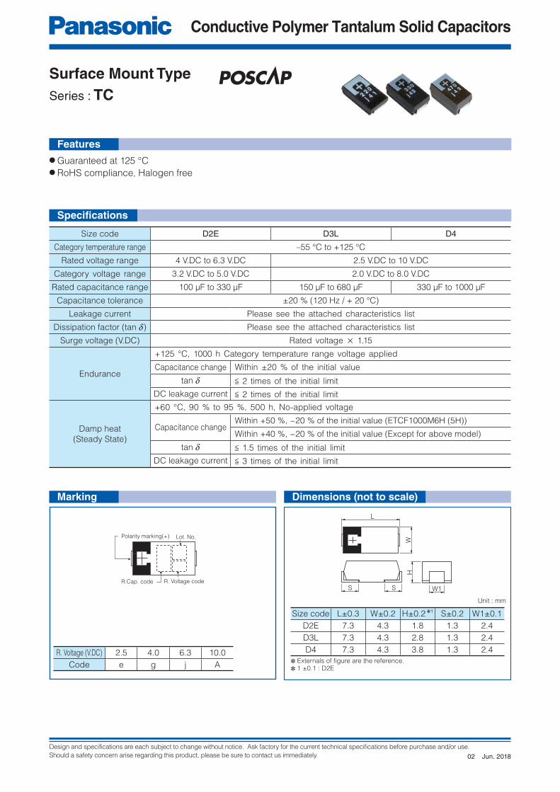
● Guaranteed at 125 °C● RoHS compliance, Halogen free
Features
Size code D2E D3L D4
Category temperature range –55 °C to +125 °C
Rated voltage range 4 V.DC to 6.3 V.DC 2.5 V.DC to 10 V.DC
Category voltage range 3.2 V.DC to 5.0 V.DC 2.0 V.DC to 8.0 V.DC
Rated capacitance range 100 µF to 330 µF 150 µF to 680 µF 330 µF to 1000 µF
Capacitance tolerance ±20 % (120 Hz / + 20 °C)
Leakage current Please see the attached characteristics list
Dissipation factor (tan d) Please see the attached characteristics list
Surge voltage (V.DC) Rated voltage × 1.15
Endurance
+125 °C, 1000 h Category temperature range voltage applied
Capacitance change Within ±20 % of the initial value
tan d < 2 times of the initial limit
DC leakage current < 2 times of the initial limit
Damp heat
(Steady State)
+60 °C, 90 % to 95 %, 500 h, No-applied voltage
Capacitance changeWithin +50 %, −20 % of the initial value (ETCF1000M6H (5H))
Within +40 %, −20 % of the initial value (Except for above model)
tan d < 1.5 times of the initial limit
DC leakage current < 3 times of the initial limit
Size code L±0.3 W±0.2 H±0.2 ✽1 S±0.2 W1±0.1
D2E 7.3 4.3 1.8 1.3 2.4
D3L 7.3 4.3 2.8 1.3 2.4
D4 7.3 4.3 3.8 1.3 2.4R. Voltage (V.DC) 2.5 4.0 6.3 10.0
Code e g j A
Unit : mm
✽ Externals of fi gure are the reference.✽ 1 ±0.1 : D2E
Specifi cations
Marking Dimensions (not to scale)
Jun. 201802
Design and specifications are each subject to change without notice. Ask factory for the current technical specifications before purchase and/or use.
Should a safety concern arise regarding this product, please be sure to contact us immediately.
Conductive Polymer Tantalum Solid Capacitors
Characteristics list
SeriesRatedvoltage(V.DC)
Ratedtemp.(°C)
Categoryvoltage
(V.DC)
Categorytemp.(°C)
Ratedcapacitance(µF)
Case size (mm)Size
code
Specifications Standard Floor life
L W HRipple ✽1 current(mAr.m.s.)
ESR ✽2
(mΩ max.)tan d ✽3 LC ✽4
(µA)Part number
Min. Packaging Q'ty(pcs)
Refl owTemp
< 260°C
Refl owTemp
< 250°C
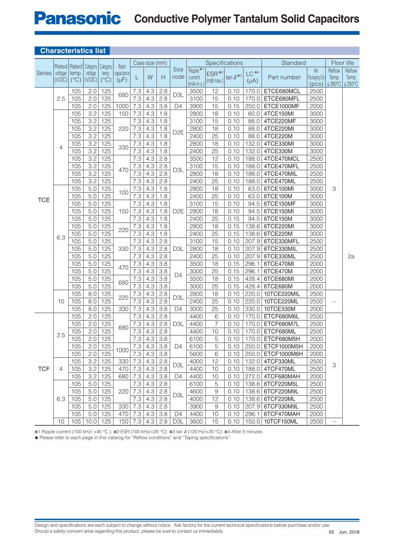
TCE
2.5
105 2.0 125 680
7.3 4.3 2.8D3L
3500 12 0.10 170.0 ETCE680MCL 2500
3
2a
105 2.0 125 7.3 4.3 2.8 3100 15 0.10 170.0 ETCE680MFL 2500
105 2.0 125 1000 7.3 4.3 3.8 D4 3900 15 0.15 250.0 ETCE1000MF 2000
4
105 3.2 125 150 7.3 4.3 1.8
D2E
2800 18 0.10 60.0 4TCE150MI 3000
105 3.2 125
220
7.3 4.3 1.8 3100 15 0.10 88.0 4TCE220MF 3000
105 3.2 125 7.3 4.3 1.8 2800 18 0.10 88.0 4TCE220MI 3000
105 3.2 125 7.3 4.3 1.8 2400 25 0.10 88.0 4TCE220M 3000
105 3.2 125 330
7.3 4.3 1.8 2800 18 0.10 132.0 4TCE330MI 3000
105 3.2 125 7.3 4.3 1.8 2400 25 0.10 132.0 4TCE330M 3000
105 3.2 125
470
7.3 4.3 2.8
D3L
3500 12 0.10 188.0 4TCE470MCL 2500
105 3.2 125 7.3 4.3 2.8 3100 15 0.10 188.0 4TCE470MFL 2500
105 3.2 125 7.3 4.3 2.8 2800 18 0.10 188.0 4TCE470MIL 2500
105 3.2 125 7.3 4.3 2.8 2400 25 0.10 188.0 4TCE470ML 2500
6.3
105 5.0 125 100
7.3 4.3 1.8
D2E
2800 18 0.10 63.0 6TCE100MI 3000
105 5.0 125 7.3 4.3 1.8 2400 25 0.10 63.0 6TCE100M 3000
105 5.0 125
150
7.3 4.3 1.8 3100 15 0.10 94.5 6TCE150MF 3000
105 5.0 125 7.3 4.3 1.8 2800 18 0.10 94.5 6TCE150MI 3000
105 5.0 125 7.3 4.3 1.8 2400 25 0.15 94.5 6TCE150M 3000
105 5.0 125 220
7.3 4.3 1.8 2800 18 0.15 138.6 6TCE220MI 3000
105 5.0 125 7.3 4.3 1.8 2400 25 0.15 138.6 6TCE220M 3000
105 5.0 125
330
7.3 4.3 2.8
D3L
3100 15 0.10 207.9 6TCE330MFL 2500
105 5.0 125 7.3 4.3 2.8 2800 18 0.10 207.9 6TCE330MIL 2500
105 5.0 125 7.3 4.3 2.8 2400 25 0.10 207.9 6TCE330ML 2500
105 5.0 125 470
7.3 4.3 3.8
D4
3500 18 0.15 296.1 6TCE470MI 2000
105 5.0 125 7.3 4.3 3.8 3000 25 0.15 296.1 6TCE470M 2000
105 5.0 125 680
7.3 4.3 3.8 3500 18 0.15 428.4 6TCE680MI 2000
105 5.0 125 7.3 4.3 3.8 3000 25 0.15 428.4 6TCE680M 2000
10
105 8.0 125 220
7.3 4.3 2.8D3L
2800 18 0.10 220.0 10TCE220MIL 2500
–105 8.0 125 7.3 4.3 2.8 2400 25 0.10 220.0 10TCE220ML 2500
105 8.0 125 330 7.3 4.3 3.8 D4 3000 25 0.10 330.0 10TCE330M 2000
TCF
2.5
105 2.0 125
680
7.3 4.3 2.8
D3L
4400 6 0.10 170.0 ETCF680M6L 2500
3
105 2.0 125 7.3 4.3 2.8 4400 7 0.10 170.0 ETCF680M7L 2500
105 2.0 125 7.3 4.3 2.8 4400 10 0.10 170.0 ETCF680ML 2500
105 2.0 125 7.3 4.3 3.8
D4
6100 5 0.10 170.0 ETCF680M5H 2000
105 2.0 1251000
7.3 4.3 3.8 6100 5 0.10 250.0 ETCF1000M5H 2000
105 2.0 125 7.3 4.3 3.8 5600 6 0.10 250.0 ETCF1000M6H 2000
4
105 3.2 125 330 7.3 4.3 2.8D3L
4000 12 0.10 132.0 4TCF330ML 2500
105 3.2 125 470 7.3 4.3 2.8 4400 10 0.10 188.0 4TCF470ML 2500
105 3.2 125 680 7.3 4.3 3.8 D4 4400 10 0.10 272.0 4TCF680MAH 2000
6.3
105 5.0 125
220
7.3 4.3 2.8
D3L
6100 5 0.10 138.6 6TCF220M5L 2500
105 5.0 125 7.3 4.3 2.8 4600 9 0.10 138.6 6TCF220M9L 2500
105 5.0 125 7.3 4.3 2.8 4000 12 0.10 138.6 6TCF220ML 2500
105 5.0 125 330 7.3 4.3 2.8 3900 9 0.10 207.9 6TCF330M9L 2500
105 5.0 125 470 7.3 4.3 3.8 D4 4400 10 0.10 296.1 6TCF470MAH 2000
10 105 10.0 125 150 7.3 4.3 2.8 D3L 3600 15 0.10 150.0 10TCF150ML 2500 –
✽1 Ripple current (100 kHz/ +45 °C ), ✽2 ESR (100 kHz/+20 °C) ✽3 tan d (120 Hz/+20 °C) ✽4 After 5 minutes
◆ Please refer to each page in this catarog for “Reflow conditions” and “Taping specifications”.
Jun. 201802
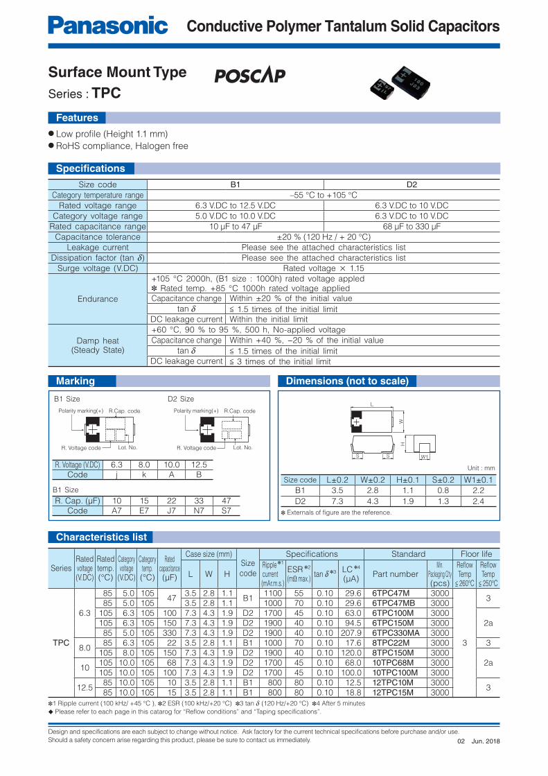
Design and specifications are each subject to change without notice. Ask factory for the current technical specifications before purchase and/or use.
Should a safety concern arise regarding this product, please be sure to contact us immediately.
Conductive Polymer Tantalum Solid Capacitors
S W1
HL
W
S
R. Voltage code Lot. No.
R.Cap. codePolarity marking(+)
R. Voltage code Lot. No.
R.Cap. codePolarity marking(+)
Surface Mount Type
Series : TPC
Features
● Low profi le (Height 1.1 mm)● RoHS compliance, Halogen free
Size code B1 D2Category temperature range –55 °C to +105 °C
Rated voltage range 6.3 V.DC to 12.5 V.DC 6.3 V.DC to 10 V.DC
Category voltage range 5.0 V.DC to 10.0 V.DC 6.3 V.DC to 10 V.DC
Rated capacitance range 10 μF to 47 μF 68 μF to 330 μF
Capacitance tolerance ±20 % (120 Hz / + 20 °C)
Leakage current Please see the attached characteristics list
Dissipation factor (tan d) Please see the attached characteristics list
Surge voltage (V.DC) Rated voltage × 1.15
Endurance
+105 °C 2000h, (B1 size : 1000h) rated voltage appled ✽ Rated temp. +85 °C 1000h rated voltage applied
Capacitance change Within ±20 % of the initial value
tan d < 1.5 times of the initial limit
DC leakage current Within the initial limit
Damp heat(Steady State)
+60 °C, 90 % to 95 %, 500 h, No-applied voltage
Capacitance change Within +40 %, −20 % of the initial value
tan d < 1.5 times of the initial limit
DC leakage current < 3 times of the initial limit
Size code L±0.2 W±0.2 H±0.1 S±0.2 W1±0.1
B1 3.5 2.8 1.1 0.8 2.2
D2 7.3 4.3 1.9 1.3 2.4
R. Voltage (V.DC) 6.3 8.0 10.0 12.5Code j k A B
R. Cap. (μF) 10 15 22 33 47Code A7 E7 J7 N7 S7
SeriesRatedvoltage(V.DC)
Ratedtemp.(°C)
Categoryvoltage
(V.DC)
Categorytemp.(°C)
Ratedcapacitance(μF)
Case size (mm)Size
code
Specifications Standard Floor life
L W HRipple ✽1 current(mAr.m.s.)
ESR ✽2
(mΩ max.)tan d ✽3 LC ✽4
(μA)Part number
Min. Packaging Q'ty(pcs)
Refl owTemp
< 260°C
Refl owTemp
< 250°C
TPC
6.3
85 5.0 105 47
3.5 2.8 1.1B1
1100 55 0.10 29.6 6TPC47M 3000
3
3 85 5.0 105 3.5 2.8 1.1 1000 70 0.10 29.6 6TPC47MB 3000105 6.3 105 100 7.3 4.3 1.9 D2 1700 45 0.10 63.0 6TPC100M 3000
2a105 6.3 105 150 7.3 4.3 1.9 D2 1900 40 0.10 94.5 6TPC150M 3000 85 5.0 105 330 7.3 4.3 1.9 D2 1900 40 0.10 207.9 6TPC330MA 3000
8.0 85 6.3 105 22 3.5 2.8 1.1 B1 1000 70 0.10 17.6 8TPC22M 3000 3105 8.0 105 150 7.3 4.3 1.9 D2 1900 40 0.10 120.0 8TPC150M 3000
2a10
105 10.0 105 68 7.3 4.3 1.9 D2 1700 45 0.10 68.0 10TPC68M 3000105 10.0 105 100 7.3 4.3 1.9 D2 1700 45 0.10 100.0 10TPC100M 3000
12.5 85 10.0 105 10 3.5 2.8 1.1 B1 800 80 0.10 12.5 12TPC10M 3000
3 85 10.0 105 15 3.5 2.8 1.1 B1 800 80 0.10 18.8 12TPC15M 3000
✽1 Ripple current (100 kHz/ +45 °C ), ✽2 ESR (100 kHz/+20 °C) ✽3 tan d (120 Hz/+20 °C) ✽4 After 5 minutes
◆ Please refer to each page in this catarog for “Reflow conditions” and “Taping specifications”.
Unit : mm
Marking
✽ Externals of fi gure are the reference.
B1 Size
B1 Size D2 Size
Dimensions (not to scale)
Characteristics list
Specifi cations
Jun. 201802
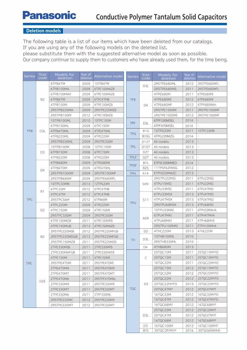
Conductive Polymer Tantalum Solid Capacitors
Deletion models
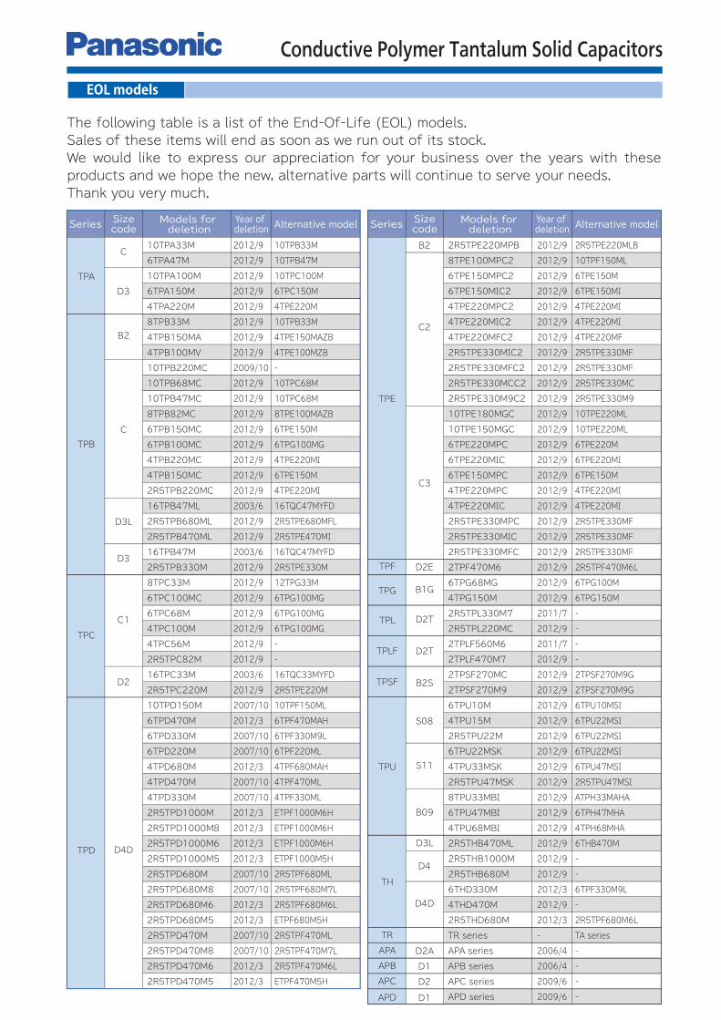
Conductive Polymer Tantalum Solid Capacitors
EOL models

Please contact Factory
CAUTION AND WARNING
The information in this catalog is valid as of March 2018.
1. The electronic components contained in this catalog are designed and produced for use in home electric appliances, office equipment, information equipment,communications equipment, and other general purpose electronic devices. Before use of any of these components for equipment that requires a high degree of safety, such as medical instruments, aerospace equipment, disaster-prevention equipment, security equipment, vehicles (automobile, train, vessel), please be sure to contact our sales representative corporation.
2. When applying one of these components for equipment requiring a high degree of safety, no matter what sort of application it might be, be sure to install a protective circuit or redundancy arrangement to enhance the safety of your equipment. In addition, please carry out the safety test on your own responsibility.
3. When using our products, no matter what sort of equipment they might be used for, be sure to make a written agreement on the specifications with us in advance.
4. Technical information contained in this catalog is intended to convey examples of typical performances and or applications and is not intended to make any warranty with respect to the intellectual property rights or any other related rights of our company or any third parties nor grant any license under such rights.
5. In order to export products in this catalog, the exporter may be subject to the export license requirement under the Foreign Exchange and Foreign Trade Law of Japan.
6. No ozone-depleting substances (ODSs) under the Montreal Protocol are used in the manufacturing processes of Automotive & Industrial Systems Company, Panasonic Corporation.