product specification - genemco · description 1 description irb 2400 is a 6-axis industrial robot,...
TRANSCRIPT
Product SpecificationIRB 2400
ABB Flexible Automation
Description
1 Description
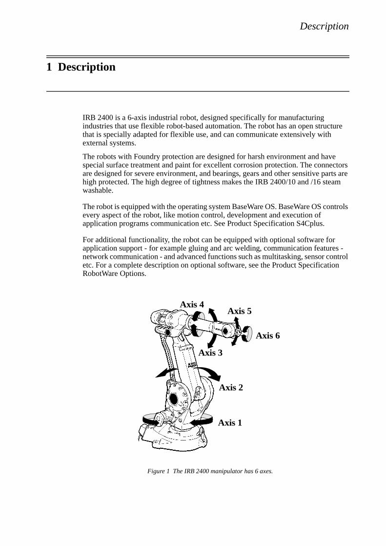
IRB 2400 is a 6-axis industrial robot, designed specifically for manufacturing industries that use flexible robot-based automation. The robot has an open structure that is specially adapted for flexible use, and can communicate extensively with external systems.
The robots with Foundry protection are designed for harsh environment and have special surface treatment and paint for excellent corrosion protection. The connectors are designed for severe environment, and bearings, gears and other sensitive parts are high protected. The high degree of tightness makes the IRB 2400/10 and /16 steam washable.
The robot is equipped with the operating system BaseWare OS. BaseWare OS controls every aspect of the robot, like motion control, development and execution of application programs communication etc. See Product Specification S4Cplus.
For additional functionality, the robot can be equipped with optional software for application support - for example gluing and arc welding, communication features - network communication - and advanced functions such as multitasking, sensor control etc. For a complete description on optional software, see the Product Specification RobotWare Options.
Figure 1 The IRB 2400 manipulator has 6 axes.
Axis 6
Axis 1
Axis 3
Axis 5Axis 4
Axis 2
Description
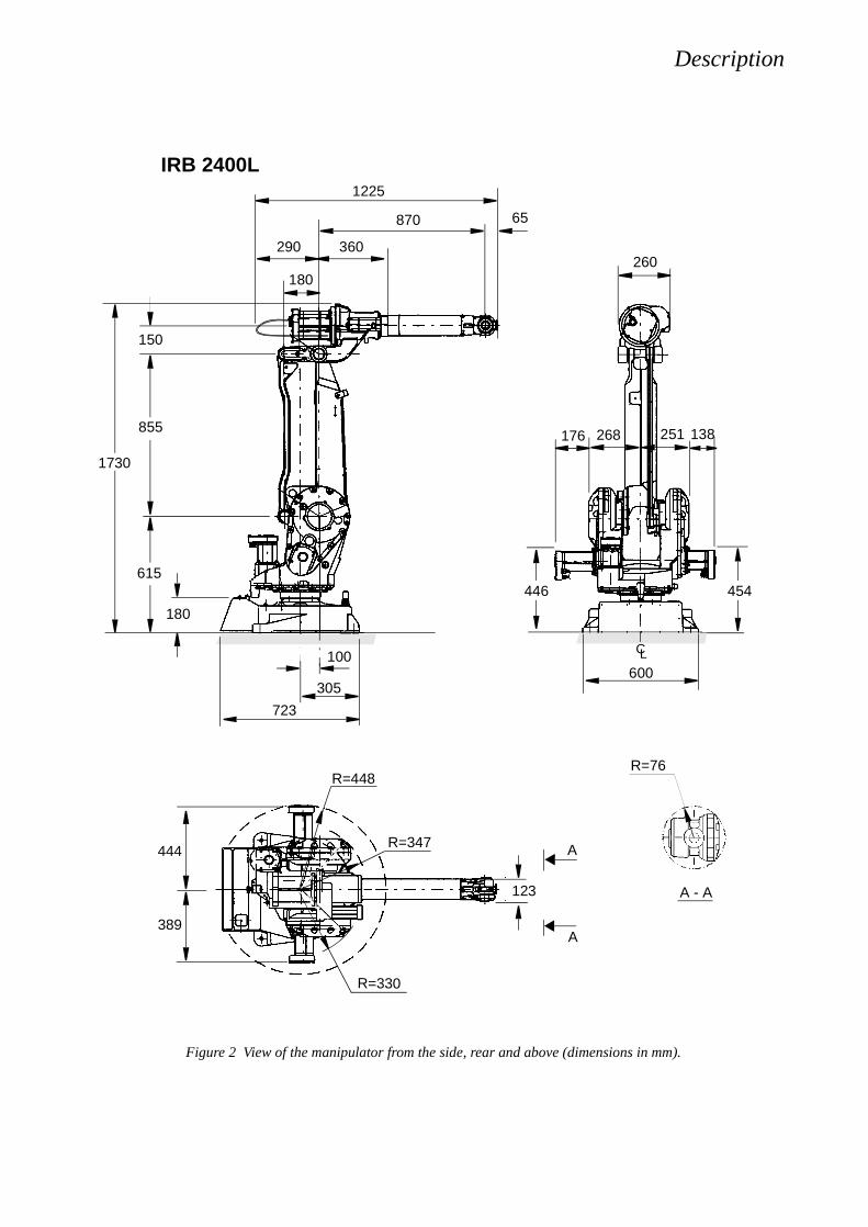
Figure 2 View of the manipulator from the side, rear and above (dimensions in mm).
290
1225
R=448
260
123
65
100
723
305
1730
389
150
855
615
180
870
360
IRB 2400L
600
R=76
A - A
444
446
268 251
454
CL
R=347
R=330
A
A
176 138
180
Description
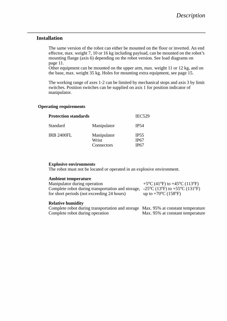
Installation
The same version of the robot can either be mounted on the floor or inverted. An end effector, max. weight 7, 10 or 16 kg including payload, can be mounted on the robot’s mounting flange (axis 6) depending on the robot version. See load diagrams on page 11. Other equipment can be mounted on the upper arm, max. weight 11 or 12 kg, and on the base, max. weight 35 kg. Holes for mounting extra equipment, see page 15.
The working range of axes 1-2 can be limited by mechanical stops and axis 3 by limit switches. Position switches can be supplied on axis 1 for position indicator of manipulator.
Operating requirements
Protection standards IEC529
Standard Manipulator IP54
IRB 2400FL Manipulator IP55Wrist IP67Connectors IP67
Explosive environmentsThe robot must not be located or operated in an explosive environment.
Ambient temperatureManipulator during operation +5oC (41oF) to +45oC (113oF)Complete robot during transportation and storage, -25oC (13oF) to +55oC (131oF)for short periods (not exceeding 24 hours) up to +70oC (158oF)
Relative humidityComplete robot during transportation and storage Max. 95% at constant temperatureComplete robot during operation Max. 95% at constant temperature
Description
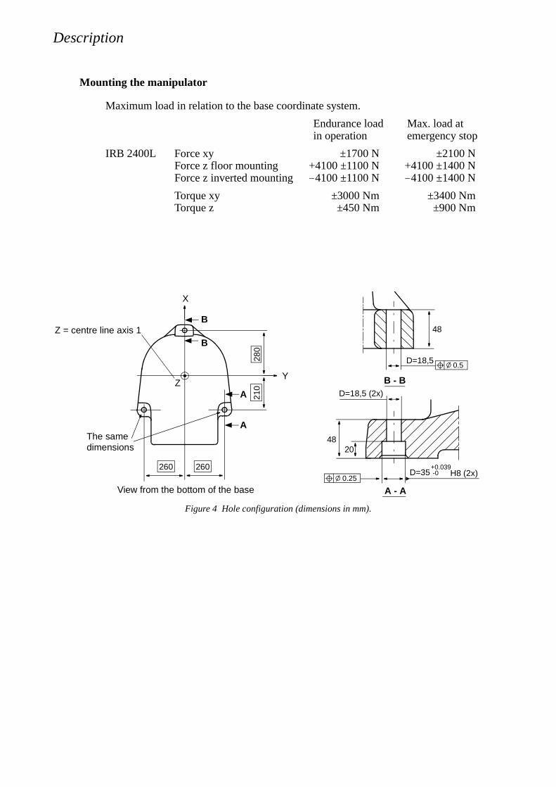
Mounting the manipulator
Maximum load in relation to the base coordinate system.
Endurance load Max. load at in operation emergency stop
IRB 2400L Force xy ±1700 N ±2100 NForce z floor mounting +4100 ±1100 N +4100 ±1400 NForce z inverted mounting -4100 ±1100 N -4100 ±1400 N
Torque xy ±3000 Nm ±3400 NmTorque z ±450 Nm ±900 Nm
Figure 4 Hole configuration (dimensions in mm).
0.25D=35
48
A
Z
280
D=18,5 (2x)
H8 (2x)+0.039-0
20
A - A
A
260
210
X
Y
View from the bottom of the base
Z = centre line axis 1
The same
260
B
B48
D=18,5
B - B
0.5
dimensions
Description
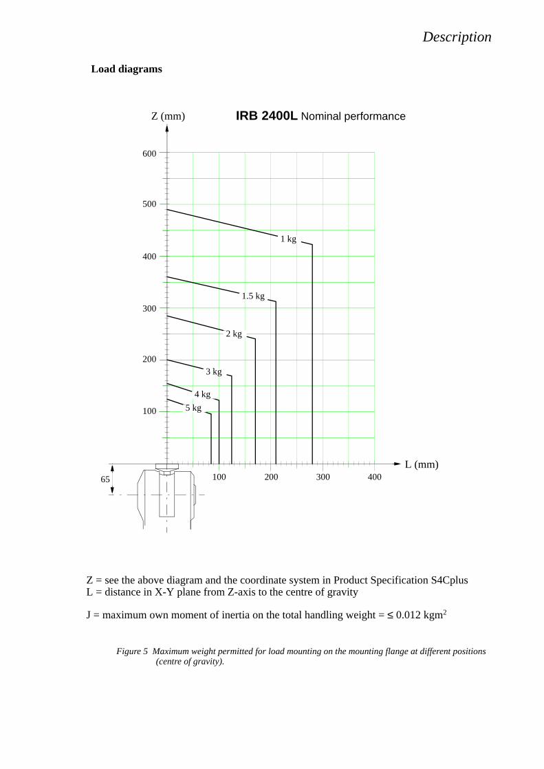
Load diagrams
Figure 5 Maximum weight permitted for load mounting on the mounting flange at different positions (centre of gravity).
Z = see the above diagram and the coordinate system in Product Specification S4CplusL = distance in X-Y plane from Z-axis to the centre of gravity
J = maximum own moment of inertia on the total handling weight = ≤ 0.012 kgm2
100
200
300
400
500
600
100 200 300
Z (mm)
L (mm)40065
1 kg
1.5 kg
2 kg
3 kg
4 kg
5 kg
IRB 2400L Nominal performance
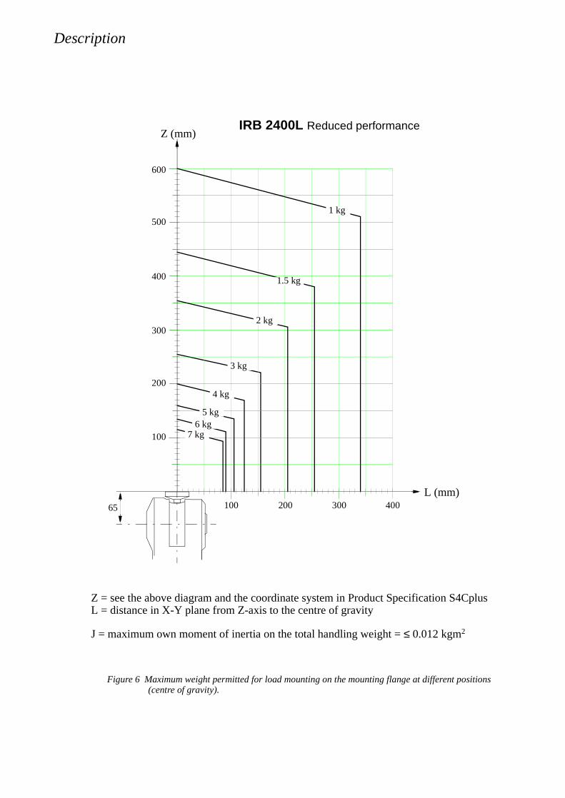
Description
Figure 6 Maximum weight permitted for load mounting on the mounting flange at different positions (centre of gravity).
100
200
300
400
500
600
100 200 300
Z (mm)
L (mm)40065
IRB 2400L Reduced performance
1 kg
1.5 kg
2 kg
3 kg
5 kg6 kg
7 kg
4 kg
Z = see the above diagram and the coordinate system in Product Specification S4CplusL = distance in X-Y plane from Z-axis to the centre of gravity
J = maximum own moment of inertia on the total handling weight = ≤ 0.012 kgm2

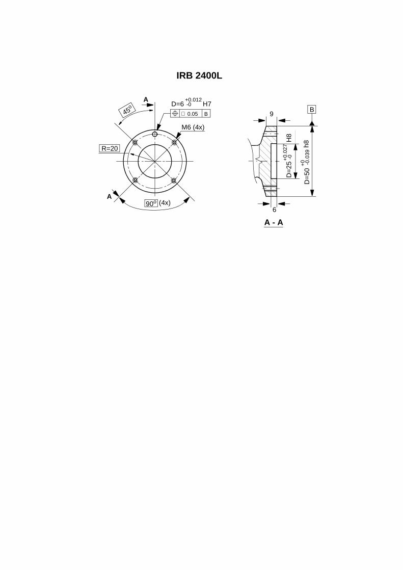
Mounting equipment
The robot is supplied with tapped holes on the upper arm and on the base for mounting extra equipment.
Figure 9 The shaded area indicates the permitted positions (centre of gravity) for any extra equipment mounted in the holes (dimensions in mm).
IRB 2400L
M8 (2x)Depth 14
400
300
Max. 10kg
A A
D=50150
Max. 35 kg total
150135
M8 (3x) R=92Depth 16
120o (3x)
B
B
B - B
38o
C - C
C
C
CL
400 470D=2
00
170
30
Max. 1kg
120o (3x)
38o
M8 (3x) R=77Depth 16
A - A
67
D D
37
70 (2x)
62
37
D - D
Depth 9
M5 (2x)
The rear side of the manipulator
45o D=6 H7
M6 (4x)
R=20
A
A
∅ 0.05 B
(4x)90o
IRB 2400L
6
D=2
5
9
A - A
D=
50 h
8
B
H8
+0.
027
-0
+0 -0.0
39
+0.012-0
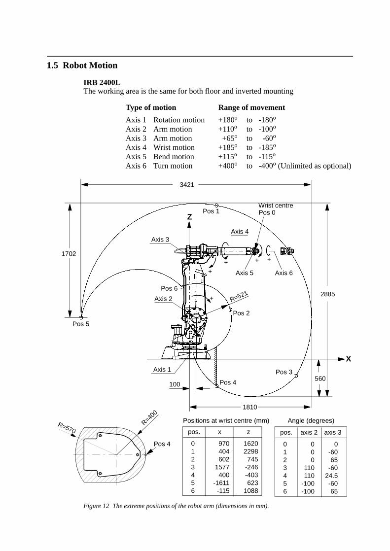
1.5 Robot Motion
IRB 2400L The working area is the same for both floor and inverted mounting
Type of motion Range of movement
Axis 1 Rotation motion +180o to -180o Axis 2 Arm motion +110o to -100o Axis 3 Arm motion +65o to -60o Axis 4 Wrist motion +185o to -185o Axis 5 Bend motion +115o to -115o Axis 6 Turn motion +400o to -400o (Unlimited as optional)
Figure 12 The extreme positions of the robot arm (dimensions in mm).
Pos 4
Pos 5
Pos 6
Pos 2
Pos 1
Pos 3
R=521
+++
Axis 4Axis 3
Axis 5 Axis 6
Axis 2
Axis 1
100
1810
pos. axis 2 axis 3
0123456
000
110110
-100-100
0-6065
-6024.5-6065
Angle (degrees)R=570R=40
0
Pos 4
1702
3421
2885
560
Wrist centre
X
Z
pos. x
0123456
Positions at wrist centre (mm)
z
16202298745
-246-403623
1088
+
Pos 0
+
970404602
1577400
-1611-115
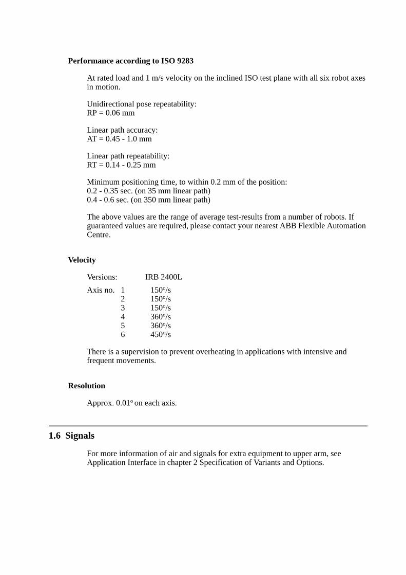
Performance according to ISO 9283
At rated load and 1 m/s velocity on the inclined ISO test plane with all six robot axes in motion.
Unidirectional pose repeatability:RP = 0.06 mm
Linear path accuracy:AT = 0.45 - 1.0 mm
Linear path repeatability:RT = 0.14 - 0.25 mm
Minimum positioning time, to within 0.2 mm of the position:0.2 - 0.35 sec. (on 35 mm linear path)0.4 - 0.6 sec. (on 350 mm linear path)
The above values are the range of average test-results from a number of robots. If guaranteed values are required, please contact your nearest ABB Flexible Automation Centre.
Velocity
Versions: IRB 2400L
Axis no. 1 150o/s2 150o/s3 150o/s4 360o/s5 360o/s6 450o/s
There is a supervision to prevent overheating in applications with intensive and frequent movements.
Resolution
Approx. 0.01o on each axis.
1.6 Signals
For more information of air and signals for extra equipment to upper arm, see Application Interface in chapter 2 Specification of Variants and Options.
2 Specification of Variants and Options
The different variants and options for the IRB 2400 are described below.The same numbers are used here as in the Specification form. For controller options, see Product Specification S4Cplus, and for software options, see Product Specification RobotWare Options.
1 MANIPULATOR
VARIANTS
Standard Foundry (requires option 035) (requires option 036)
021 IRB 2400L IRB 2400FL
IRB 2400 Application Version - Handling capacity
Application: F Robot adapted for foundry environments. Degree of protection as in chapter 1.3. The manipulator is finished with a special coating.
Reach: Specifies the max. reach at the wrist centre.Handling capacity: Specifies the nominal handling capacity.
Manipulator colour
330 The manipulator is painted with ABB orange.
353 The manipulator is painted with ABB orange Foundry.
331- Colours according to RAL-codes. Not available for Foundry protection348
Protection
035 Standard
036 FoundryRobot adapted for foundry environments. Degree of protection as in Chapter 1.3. The manipulator is specially painted and finished. Only available colour is ABB orange Foundry.
APPLICATION INTERFACE
Air supply and signals for extra equipment to upper arm
For connection of extra equipment on the manipulator, there are cables integrated into the manipulator’s cabling, one FCI UT07 14 12SH44N connector and one FCI UT07 18 23SH44N connector on the rear part of the upper arm.A hose for compressed air is also integrated into the manipulator. There is an inlet
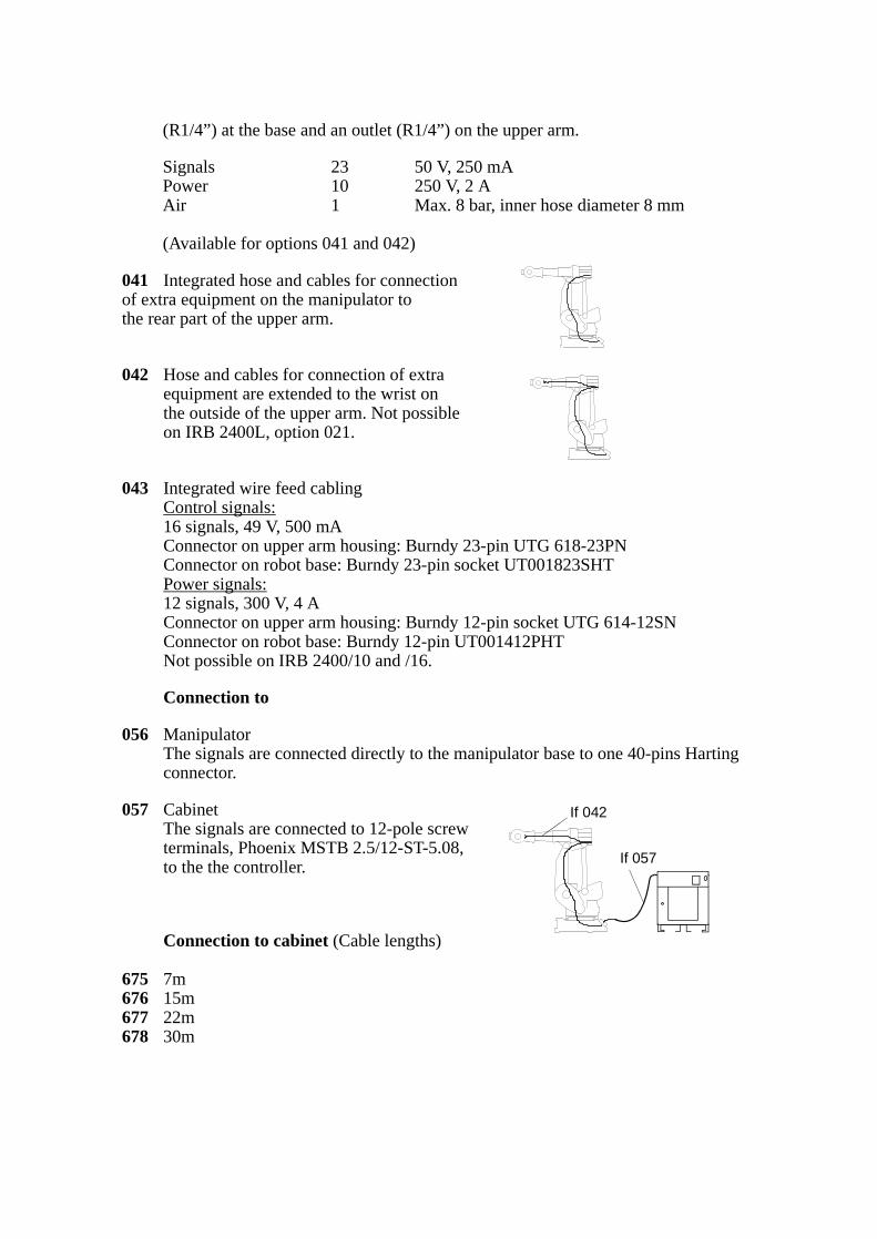
(R1/4”) at the base and an outlet (R1/4”) on the upper arm.
Signals 23 50 V, 250 mAPower 10 250 V, 2 AAir 1 Max. 8 bar, inner hose diameter 8 mm
(Available for options 041 and 042)
041 Integrated hose and cables for connection of extra equipment on the manipulator to the rear part of the upper arm.
042 Hose and cables for connection of extra equipment are extended to the wrist on the outside of the upper arm. Not possibleon IRB 2400L, option 021.
043 Integrated wire feed cablingControl signals: 16 signals, 49 V, 500 mAConnector on upper arm housing: Burndy 23-pin UTG 618-23PNConnector on robot base: Burndy 23-pin socket UT001823SHTPower signals: 12 signals, 300 V, 4 AConnector on upper arm housing: Burndy 12-pin socket UTG 614-12SNConnector on robot base: Burndy 12-pin UT001412PHTNot possible on IRB 2400/10 and /16.
Connection to
056 ManipulatorThe signals are connected directly to the manipulator base to one 40-pins Harting connector.
057 CabinetThe signals are connected to 12-pole screw terminals, Phoenix MSTB 2.5/12-ST-5.08, to the the controller.
Connection to cabinet (Cable lengths)
675 7m676 15m677 22m678 30m
If 042
If 057
EQUIPMENT
691 Safety lampA safety lamp with an orange fixed light can be mounted on the manipulator.The lamp is active in MOTORS ON mode.The safety lamp is required on a UL/UR approved robot.
058 DressingMounting of extra equipment, e.g. tool system on robot before delivery, ordered from ABB Flexible Automation/Department U.
POSITION SWITCH
Switches indicating the position of axis 1.A design with two stationary or 1, 2 or 3 adjustable switches is available. The switches are manufactured by Telemecanique or Burnstein, and of type forced disconnect.
Note The switches are not recommended to be used in severe environment with sand or chips.
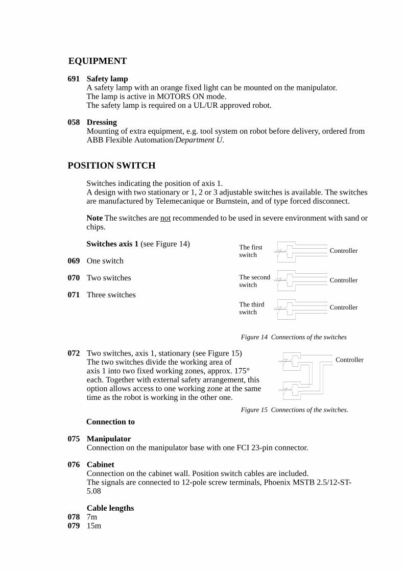
Switches axis 1 (see Figure 14)
069 One switch
070 Two switches
071 Three switches
Figure 14 Connections of the switches
072 Two switches, axis 1, stationary (see Figure 15)The two switches divide the working area ofaxis 1 into two fixed working zones, approx. 175°each. Together with external safety arrangement, thisoption allows access to one working zone at the sametime as the robot is working in the other one.
Figure 15 Connections of the switches.
Connection to
075 ManipulatorConnection on the manipulator base with one FCI 23-pin connector.
076 CabinetConnection on the cabinet wall. Position switch cables are included.The signals are connected to 12-pole screw terminals, Phoenix MSTB 2.5/12-ST-5.08
Cable lengths078 7m079 15m
Controller
Controller
Controller
The firstswitch
The secondswitch
The thirdswitch
Controller
080 22m081 30m
WORKING RANGE LIMIT
To increase the safety of the robot, the working range of axes 1, 2 and 3 can be restricted
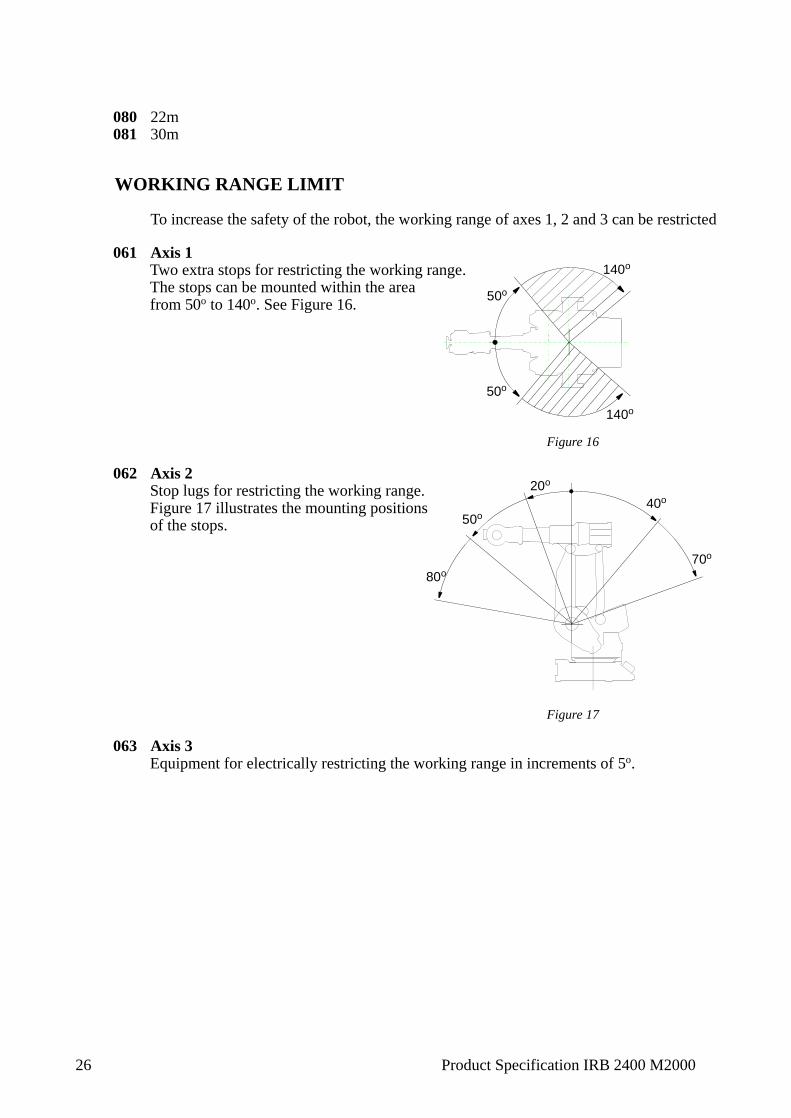
061 Axis 1Two extra stops for restricting the working range.The stops can be mounted within the areafrom 50o to 140o. See Figure 16.
Figure 16
062 Axis 2Stop lugs for restricting the working range.Figure 17 illustrates the mounting positions of the stops.
Figure 17
063 Axis 3Equipment for electrically restricting the working range in increments of 5o.
140o
50o
50o
140o
80o
50o
20o
40o
70o
26 Product Specification IRB 2400 M2000
Accessories
3 Accessories
There is a range of tools and equipment available, specially designed for the robot.
Basic software and software options for robot and PC
For more information, see Product Specification S4Cplus, and Product Specification RobotWare Options.
Robot Peripherals
- Track Motion
- Tool System
- Motor Units