product overview - salsnes filter & sfk product components ... module 4 1 200 400 30 17 module 6...
TRANSCRIPT

Eco-efficient solids separation
Product Overview
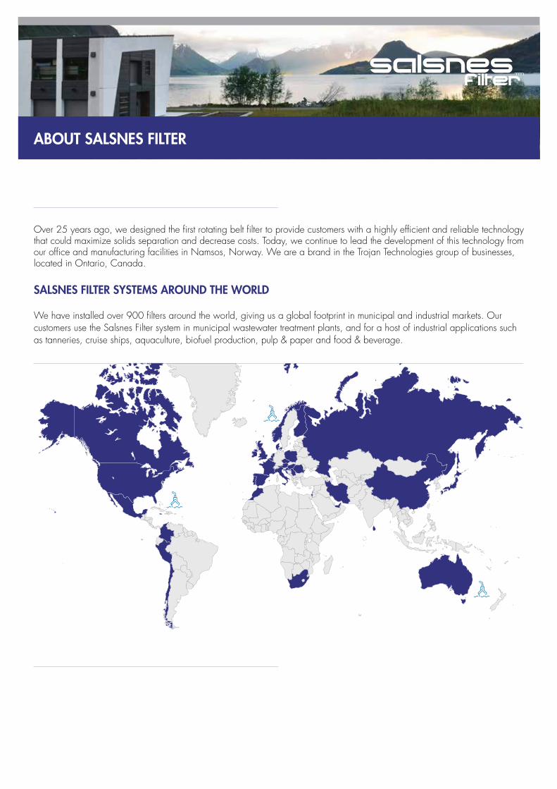
ABOUT SALSNES FILTER
Over 25 years ago, we designed the first rotating belt filter to provide customers with a highly efficient and reliable technology that could maximize solids separation and decrease costs. Today, we continue to lead the development of this technology from our office and manufacturing facilities in Namsos, Norway. We are a brand in the Trojan Technologies group of businesses, located in Ontario, Canada.
SALSNES FILTER SYSTEMS AROUND THE WORLD
We have installed over 900 filters around the world, giving us a global footprint in municipal and industrial markets. Our customers use the Salsnes Filter system in municipal wastewater treatment plants, and for a host of industrial applications such as tanneries, cruise ships, aquaculture, biofuel production, pulp & paper and food & beverage.

AN ALTERNATIVE TO CONVENTIONAL PRIMARY TREATMENT
A Salsnes Filter system can completely replace conventional primary solids separation. Or, it can augment existing primary treatment to improve plant performance and reduce overall costs.
Compared to conventional systems, a Salsnes Filter system can offer:
SF SYSTEMSFree-standing & enclosed
SF2000
SF4000
SF6000
SFK200
SFK400
SFK600
SF500
SF1000
20 ft. Containerized Demonstration
System
10 ft. Trailer Demonstration
System
Bench Scale Tester
SFK SYSTEMSOpen for concrete channel installation
DEMONSTRATION & SMALL SYSTEMS
OUR PRODUCTS
• 30-60% lower investment costs
• 1/10th the land requirements
• Integrated thickening and optional dewatering
• Significantly lower lifecycle costs
• Smaller volume of drier sludge that reduces disposal costs
• Less civil works
• Fully automated equipment
• Optimal removal of TSS to ease demand on downstream biological treatment
- 30-60% removal in a typical municipal installation
- up to 80% removal when a polymer is used
• Higher Volatile Solids content in primary sludge for biogas production
• Fast and easy maintenance
• Lower operating costs

SF & SFK PRODUCT COMPONENTS
Filtermesh & Cogwheel
The filtermesh is made of polyethylene and is very durable. The way it’s mounted and tensioned to the cogwheel is patented - it improves performance and allows the filter to handle higher flow rates and solids loadings, increasing treatment capacity in a smaller footprint.
Access Hatch
Enables quick visual inspections of performance and internal components.
Hot or Cold Water Flush
A hot water or cold water high pressure flush is available to those facilities that have a high concentration of fat, oil and grease (FOG) in their wastewater. Operating only two – four times daily, this flush effectively cleans the hard- to-remove FOG from filtermesh openings.
Air Knife
The Air Knife filtermesh cleaning system starts automatically when the mesh begins to rotate. It uses compressed air to clean, which has many benefits compared to scrapers, brushes or water-based cleaning systems. Air is gentler on the mesh (to elongate its life) and on particles (so they don’t break into smaller pieces). Air cleaning also keeps sludge drier for more effective dewatering.
1
1
3
3
2
2
4
4

Integrated Dewatering
To save space and money, the enclosed SF systems contain an optional integrated dewatering process. Sludge drops into the collection area from the thickening process at 3 – 8 % DM and is conveyed across the unit by an auger. It can then be fed to a sludge stabilization process (e.g.
direct digester feed); Or processed further through the dewatering unit to produce sludge that is 20 –30% DM (without the need for any additional dewatering equipment).
Quick Connects
You will find only quick connects on the system for fast and easy maintenance.
External Dewatering
Common Dewatering: For larger installations, this unit is available to dewater sludge from multiple filters. It can apply a higher pressure to produce even drier sludge (20 – 40% DM typical).
Vacuum System: Ideal for sludge that is harder to dewater, our vacuum system can be installed to produce sludge as dry as 30% DM before the integrated dewatering auger.
Control Power Panel (CPP)
The CPP houses a Programmable Logic Controller (PLC) that makes this a completely automated system, ideal for remote or unstaffed facilities. A water pressure sensor tells the unit when to rotate the filtermesh (and at what speed), while the PLC simultaneously starts the Air Knife and sludge screw press.

SF SYSTEMS
Free-standing and enclosed systems for municipal and industrial applications.SF2000, SF4000, SF6000
Solids Separation with Integrated Sludge Thickening and Dewatering
In SF systems, wastewater enters the inlet and is distributed (to prevent particle breakage) onto the filtermesh for solids separation. The filtermesh rotates like a conveyor belt, transporting sludge and enabling the thickening process. Sludge then drops into a collection area and goes through a dewatering unit (optional) before it exits the system.
Modular, Flexible Design
The modular design of the Salsnes Filter system allows for installation configurations to serve practically any capacity requirement. Single or multiple filters can be easily installed in new or existing facilities thanks to flexible design options.

SF2000/4000/6000
Specifications SF2000 SF4000 SF6000
Maximum Hydraulic Flow 144 m3/h (0.9 MGD) 288 m3/h (1.8 MGD) 576 m3/h (3.7 MGD)
Average Treated Flow 90 m3/h (0.6 MGD) 160 m3/h (1 MGD) 325 m3/h (2 MGD)
TSS Removal Efficiency 30 – 80% (design dependant)
Sludge Dry Content After Thickening 3 - 8 %
Sludge Dry Content After Integrated Dewatering 20 -30 %
Typical Operating Power Consumption 1.8 - 3.6 kW 2.1 - 4.5 kW 2.8 - 5.5 kW
Dimensions (L x W x H) 2.0 x 1.7 x 1.3 m (7 x 5.5 x 4.5’)
2.5 x 2.0 x 1.6 m (8 x 6.5 x 5.2’)
2.8 x 2.5 x 1.8 m (9 x 8.1 x 6’)
Filtermesh Sizes 850, 500, 350, 250 micron
Bedford, United Kingdom
2,365 m3/h (15 MGD)

SFK SYSTEMS
Systems for concrete channel installation in municipal and industrial markets.SFK200, SFK400, SFK600
Solids Separation, Sludge Thickeningand Dewatering
In SFK systems, wastewater flows through the channel and meets the filtermesh, where solids are separated. The filtermesh rotates, transporting sludge above the channel’s water level to the thickening stage. Thickened sludge is then dropped into a collection area when it can optionally go through a dewatering process before it exits the system.
Modular, Flexible Design
SFK Systems can be easily retrofitted into the channels at existing facilities. A group of filters can form a module which allows for a variety of installation configurations that service practically any capacity requirement.
SFK Type Number of Units
Typical hydraulic capacity (L/s) for
50 - 60% TSS removal
Typical hydraulic capacity (L/s) for 40% TSS removal
Net footprint in m2 incl. channels and sludge tanks
Energy consumption (kWh) at 40% TSS removal
Module 4 1 200 400 30 17
Module 6 1 300 600 40 25
Module 8 1 400 800 60 34
Module 10 1 600 1200 80 42
Module 12 1 800 1600 100 51
Module 12 2 1600 3200 230 102
Module 12 4 3200 6400 460 204
SFK modules and change in treatment plant capacities
One Module
Eight SFK600 Salsnes Filters treating 2000 m3/h (12.6 MGD) at the Egå Wastewater Treatment Plant in Aarhus, Denmark.
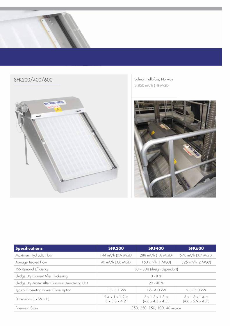
Specifications SFK200 SKF400 SFK600
Maximum Hydraulic Flow 144 m3/h (0.9 MGD) 288 m3/h (1.8 MGD) 576 m3/h (3.7 MGD)
Average Treated Flow 90 m3/h (0.6 MGD) 160 m3/h (1 MGD) 325 m3/h (2 MGD)
TSS Removal Efficiency 30 – 80% (design dependant)
Sludge Dry Content After Thickening 3 - 8 %
Sludge Dry Matter After Common Dewatering Unit 20 - 40 %
Typical Operating Power Consumption 1.3 - 3.1 kW 1.6 - 4.0 kW 2.3 - 5.0 kW
Dimensions (L x W x H) 2.4 x 1 x 1.2 m(8 x 3.3 x 4.2’)
3 x 1.3 x 1.3 m(9.6 x 4.3 x 4.5’)
3 x 1.8 x 1.4 m(9.6 x 5.9 x 4.7’)
Filtermesh Sizes 350, 250, 150, 100, 40 micron
Salmar, Follafoss, Norway
2,850 m3/h (18 MGD)SFK200/400/600

DEMONSTRATION & SMALL SYSTEMS
Bench Scale TesterA simple and quick way to characterize your wastewater and show the efficacy of solids removal using various-sized filtermesh.
The Bench Scale Tester is easy to transport and can be mounted on a regular water testing work bench. Fitermesh ranging from 11 to 840 microns can be tested.
Total suspended solids are measured before and after the wastewater is put through the Tester. Charting this information in the provided Excel template will show the particle size distribution of your wastewater, and how each filtermesh performed. This data helps determine which system would be best suited in a demonstration or full-scale installation.
The Bench Scale Tester comes with:
• Collection of standard meshes• Excel template for calculations • Procedure to execute the testing
Bench Scale Tester
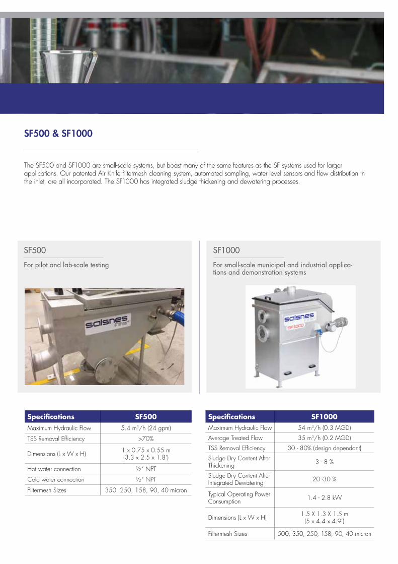
SF500 & SF1000
The SF500 and SF1000 are small-scale systems, but boast many of the same features as the SF systems used for larger applications. Our patented Air Knife filtermesh cleaning system, automated sampling, water level sensors and flow distribution in the inlet, are all incorporated. The SF1000 has integrated sludge thickening and dewatering processes.
SF500
For pilot and lab-scale testing For small-scale municipal and industrial applica-tions and demonstration systems
SF1000
Specifications SF500Maximum Hydraulic Flow 5.4 m3/h (24 gpm)
TSS Removal Efficiency >70%
Dimensions (L x W x H) 1 x 0.75 x 0.55 m (3.3 x 2.5 x 1.8’)
Hot water connection ½” NPT
Cold water connection ½” NPT
Filtermesh Sizes 350, 250, 158, 90, 40 micron
Specifications SF1000Maximum Hydraulic Flow 54 m3/h (0.3 MGD)
Average Treated Flow 35 m3/h (0.2 MGD)
TSS Removal Efficiency 30 - 80% (design dependant)
Sludge Dry Content After Thickening 3 - 8 %
Sludge Dry Content After Integrated Dewatering 20 -30 %
Typical Operating Power Consumption 1.4 - 2.8 kW
Dimensions (L x W x H) 1.5 X 1.3 X 1.5 m (5 x 4.4 x 4.9’)
Filtermesh Sizes 500, 350, 250, 158, 90, 40 micron

Control panels automatically operate the systems and also store data collected from the demonstration.
Containerized and Trailer Demonstration SystemsThe next step after bench scale testing. State-of-the art wastewater testing equipment collects data about the performance of the Salsnes Filter system with your specific wastewater.
Demonstration System Features
Our demonstration systems house either a SF500 or SF1000 unit integrated with optional polymer station, coagulation & flocculation tanks and a screw conveyor for the transportation of sludge. External requirements are simple; 3 phase electricity and connections to fresh and wastewater.
The polymer station can use emulsion polymers and is diluted online with freshwater before injection into the flocculation basin. A static mixer is in place for rapid mixing of polymers.
Wastewater Testing Equipment
The latest testing equipment is used in the systems including jar testers, Hach testing equipment, electronic balance and TSS filtration units. A 24-hour composite sampler with built-in refrigerator is also on board. The systems have several control panels, which are used for the collection and storage of data as well as the automatic operation of the system.
At the influent chamber, there are several online sensors (pH, TSS, temperature, turbidity) for automatic readings and for coagulant and polymer dosing.
DEMONSTRATION & SMALL SYSTEMS

10 Foot Trailer Demonstration System
20 Foot Containerized Demonstration System
Can be easily transported with a standard 4-wheel drive car or a truck.
Designed into a standard shipping container foreasy transportation.

Model SF1000 SF2000 SF4000 SF6000
Style Enclosed, free-standing
Material of Construction 316L Stainless Steel
Weight (Dry) 480 kg (1,058 lbs) 530 kg (1,168 lbs) 890 kg (1,962 lbs) 1,230 kg (2,711 lbs)
Standard Electrical Voltages 480/277V 3 ph, 3 wire + gnd, 60 Hz400/230V 3 ph, 3 wire + gnd, 50 Hz
Typical Operating Power Consumption 1.4 - 2.8 kW 1.8 - 3.6 kW 2.1 - 4.5 kW 2.8 - 5.5 kW
Accreditations (Electrical) CE, UL, UL approved for Class 1 Div1
Performance
Maximum Hydraulic Flow 54 m3/h (0.3 MGD)
144 m3/h (0.9 MGD)
288 m3/h (1.8 MGD)
576 m3/h (3.7 MGD)
Treated Flow (Municipal Wastewater)
35 m3/h (0.2 MGD)
90 m3/h (0.6 MGD)
160 m3/h (1.0 MGD)
325 m3/h (2 MGD)
Maximum Head Loss 440 mm (17”) 300 mm (12”) 330 mm (13”) 350 mm (14”)
TSS Removal Efficiency 30 - 80% (design dependent)
BOD Removal Efficiency 15 - 40% (design dependent)
Sludge Dry Matter After Thickening 3 – 8%
Sludge Dry Matter After Integrated Dewatering Unit 20 – 30%
Dimensions
Length x Width x Height (complete unit)
1.5 x 1.3 x 1.5 m (5 x 4.4 x 4.9’)
2 x 1.7 x 1.3 m (7 x 5.5 x 4.5’)
2.5 x 2.0 x 1.6 m (8 x 6.5 x 5.2’)
2.8 x 2.5 x 1.8 m (9 x 8.1 x 6’)
Inlet Diameter (pumped/gravity) 100 mm DIN (4“ ANSI)
150/200 mm DIN (6” / 8” ANSI)
200/350 mm DIN (8” / 14” ANSI)
250/400 mm DIN (10” / 16” ANSI)
Outlet Diameter 150 mm DIN (6” ANSI) 250 mm DIN (10” ANSI)
350 mm DIN (14” ANSI)
400 mm DIN (16” ANSI)Overflow Diameter Combined with outlet
Bottom Drain Diameter N/A 100 mm DIN (4” ANSI)
Water Connection 13 mm BSP (½” NPT) 19 mm BSP (¾” NPT)½" NPT for UL Div1
SPECIFICATIONS

Model SFK200 SFK400 SFK600
Style Concrete open channel (by others)
Material of Frame 316L Stainless Steel
Weight 510 kg (1,124 lbs) 630 kg (1,389 lbs) 745 kg (1,642 lbs)
Standard Electrical Voltages 480/277V 3 ph, 3 wire + gnd, 60 Hz400/230V 3 ph, 3 wire + gnd, 50 Hz
Typical Operating Power Consumption 1.3 - 3.1 kW 1.6 - 4.0 kW 2.3 - 5.0 kW
Accreditations (Electrical) CE, UL, UL approved for Class 1 Div1
Performance
Maximum Hydraulic Flow 144 m3/h (0.9 MGD)
288 m3/h (1.8 MGD)
576 m3/h (3.7 MGD)
Treated Flow (Municipal Wastewater)
90 m3/h (0.6 MGD)
160 m3/h (1.0 MGD)
325 m3/h (2 MGD)
Head Loss 400 mm (16”)
TSS Removal Efficiency 30 - 80% (design dependent)
BOD Removal Efficiency 15 - 40% (design dependent)
Sludge Dry Matter after Thickening 3 – 8%
Sludge Dry Matter After Common Dewatering Unit 20 – 40%
Dimensions
Length x Width x Height (frame) 2.4 x 1 x 1.2 m (8 x 3.3 x 4.2’)
3 x 1.3 x 1.3 m (9.6 x 4.3 x 4.5’)
3 x 1.8 x 1.4 m (9.6 x 5.9 x 4.7’)
Overflow Arranged in channel wall
Water Connection 13 mm BSP (½” NPT) 19 mm BSP (¾” NPT)½" NPT for UL Div1

©2017 Salsnes Filter AS
North America: T. 519.457.3400Europe: T. +47 74 27 48 60
www.salsnes-filter.com