product design of semi flexible screw · pdf fileproduct design of semi flexible screw...
TRANSCRIPT
IOSR Journal of Mechanical and Civil Engineering (IOSR-JMCE)
e-ISSN: 2278-1684,p-ISSN: 2320-334X, Volume 11, Issue 5 Ver. IV (Sep- Oct. 2014), PP 01-13 www.iosrjournals.org
www.iosrjournals.org 1 | Page
Product Design of Semi Flexible Screw Conveyor
Santanu Chakarborthy1, Anshuman Mehta
2
1(Assistant Professor, Department of Mechanical Engineering, Sikkim Manipal Institute of Technology, India) 2(UG Student, Department of Mechanical Engineering, Sikkim Manipal Institute of Technology, India)
Abstract: In this project we have endeavoured to study and create an adaptive design of semi-flexible screw
conveyor using conventional specifications and standards. A CAD model shall be developed of a three segment
screw conveyor that can function as a single unit as well as independently and also can be mix matched, thus
providing flexibility by length variation. Also applying the concept of universal joint, each of these segments can be linked at an angle, both in the horizontal and vertical planes thus providing flexibility by angle variation. The
successful design and assembly of the CAD model shall provide us a cheap, efficient and standard method of
providing flexibility in screw conveyors.
Keywords: Auger Section; Keys and Splines; Norelem Single Cardan Joint; Trough; Tonnage Capacity
I. Introduction 1.1 Theory
The screw conveyor is one of the oldest methods of conveying materials known to mankind with the
original design dating back to more than two thousand years. The first type of screw conveyor was the Archimedes' screw, used since ancient times to pump irrigation water.
A screw conveyor mechanism consists of a rotating helical screw blade, called a "flighting", usually
within a tube, to move liquid or granular materials. They are used in many bulk handling industries. Since the
screw conveyor came into general use a little over a century ago for moving grains, fine coal and other bulk
material of the times, it has come to occupy a unique place in a growing area of material handling processing.
Today, modern technology has made the screw conveyor one of the most efficient and economical methods of
moving bulk material.
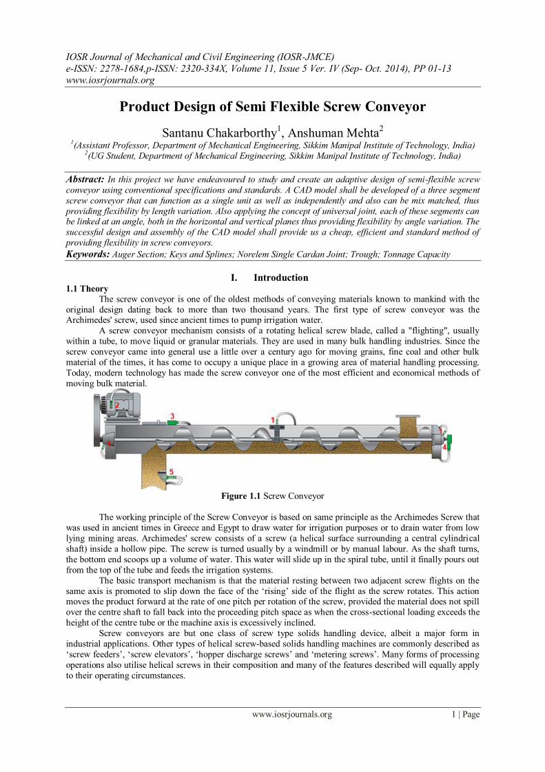
Figure 1.1 Screw Conveyor
The working principle of the Screw Conveyor is based on same principle as the Archimedes Screw that
was used in ancient times in Greece and Egypt to draw water for irrigation purposes or to drain water from low
lying mining areas. Archimedes' screw consists of a screw (a helical surface surrounding a central cylindrical
shaft) inside a hollow pipe. The screw is turned usually by a windmill or by manual labour. As the shaft turns,
the bottom end scoops up a volume of water. This water will slide up in the spiral tube, until it finally pours out
from the top of the tube and feeds the irrigation systems.
The basic transport mechanism is that the material resting between two adjacent screw flights on the
same axis is promoted to slip down the face of the ‗rising‘ side of the flight as the screw rotates. This action moves the product forward at the rate of one pitch per rotation of the screw, provided the material does not spill
over the centre shaft to fall back into the proceeding pitch space as when the cross-sectional loading exceeds the
height of the centre tube or the machine axis is excessively inclined.
Screw conveyors are but one class of screw type solids handling device, albeit a major form in
industrial applications. Other types of helical screw-based solids handling machines are commonly described as
‗screw feeders‘, ‗screw elevators‘, ‗hopper discharge screws‘ and ‗metering screws‘. Many forms of processing
operations also utilise helical screws in their composition and many of the features described will equally apply
to their operating circumstances.

Product Design of Semi Flexible Screw Conveyor
www.iosrjournals.org 2 | Page
1.2 Need
As stated above Screw Conveyors are used in a variety of situations. Some of this situations require
material to be transported over a large distance or at considerable heights. The path from receiving point to delivery point may not always be a straight one or even a constant one. Depending upon the material to be
transported, or the storage capacity of the bins, the screw conveyor may need to be adjusted.
For example when storing grains in a silo, considerable energy can be saved if the grains are first
conveyed up to a minimum height and then the conveyor is adjusted to deliver up to a greater height. Similar, in
construction sites, when material is conveyed to fill structures for pillars etc., a huge amount of power
consumption can be avoid by conveying in segmented heights by using a flexible conveyor.
1.3 Concepts Available
Till date various concepts have been developed to satisfy the need of a flexible screw conveyor. Like
some of the few below. In April 1958, Inventors Marion H Fennimore and Ivan J Stephenson invented a
Flexible Screw Auger [6] for Conveying grain. Fig.1.2, in handling bulk materials such as grain and the like, screw or auger conveyors are frequently used. However, in certain circumstances there is no open path between
the point where the material is located, and the point to which it is to be transported. In such circumstances
normal screw conveyors cannot be used. It is the principal purpose of this invention to provide a flexible screw
conveyor which may be bent around, over, or under obstacles existing in the path of transportation. A further
purpose of the invention is to provide such a device having a plurality of universally connected short auger
sections inserted in a flexible tube and rotatable supported therein, whereby to provide for substantial flexibility
without impairment of conveying ability. More specifically the invention consists in making a portable bendable
screw conveyor system by connecting a plurality of short screw conveyor or auger sections end to end by
universal joint members which themselves include auger portions, providing open cage supports for the
individual sections, which supports have bearings for the screw sections so that each support is free to turn with
respect to an endwise adjacent support on the same axis that the screw section rotates, the supports being
combined in a relatively stiff flexible tube by friction only, whereby the several supports may adjust themselves in bending of the tube to get around obstructions. The nature and advantages of the invention will appear more
clearly from the following description and the accompanying drawings wherein a preferred form of the
invention is shown. It should be understood, however, that the description and drawings are illustrative only,
and are not intended to limit the invention except insofar as it is limited by the claims.
In Figure 1.2:
Figure l is an elevated view or the invention with a portion of the tube broken away; Figure 2 is an
enlarged sectional view taken on the line 2-2 of Figure l; Figure 3 is an enlarged sectional view taken on the line
3-3`of Figure l; Figure 4 is an enlarged sectional view taken on the line d of Figure l; and Y Figure. 5 is a
perspective view of one of the 4 universal joint members, illustrating the spiral in thereon. Referring now to the
drawings, the invention as shown. Figure l, provides a portable flexible screw or auger type conveyor generally indicated at 10, which may be bent as desired to travel around corners and over obstacles in order to carry bulk
materials from one place to another.
The conveyor comprises a plurality of short auger sections 11, each of which is composed of a drive
shaft 12 with a helical auger blade 13 fixed thereto. As shown in Figure l, the shaft 12 extends outwardly at each
end beyond the ends of the blade 13. Bearing members 14 are rotatable mounted on the shaft 1l. At each end of
the blade 13. Each of the bearing members 14 has a plurality of radial rods 15 secured thereto. The rods 15
extend outwardly and are slightly longer than the radius of the auger 11. The radial rods 15l at each end of the
auger section 11 are connected by longitudinal rods 16 which are equally spaced around the circumference of
the auger 11. The rods 15 and 16 together with the bearings 14 comprise a cage surrounding each auger section
11, and supporting it for free rotation therein. As hereinbefore described, there are a plurality of the auger
sections 11. Each of these sections 11 and their surrounding cages of rods 15 and 16, are placed end to end.
Product Design of Semi Flexible Screw Conveyor
www.iosrjournals.org 3 | Page
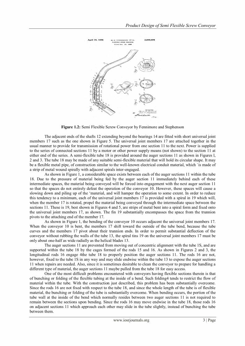
Figure 1.2: Semi Flexible Screw Conveyor by Fennimore and Stephenson
The adjacent ends of the shafts 12 extending beyond the bearings 14 are fitted with short universal joint members 17 such as the one shown in Figure 5. The universal joint members 17 are attached together in the
usual manner to provide for transmission of rotational power from one section 11 to the next. Power is supplied
to the series of connected sections 11 by a motor or other power supply means (not shown) to the section 11 at
either end of the series. A semi-flexible tube 18 is provided around the auger sections 11 as shown in Figures l,
2 and 3. The tube 18 may be made of any suitable semi-flexible material that will hold its circular shape. It may
be a flexible metal pipe, of construction similar to the well-known electrical conduit material, which `is made of
a strip of metal wound spirally with adjacent spirals inter-engaged.
As shown in Figure 1, a considerable space exists between each of the auger sections 11 within the tube
18. Due to the pressure of material being fed by the auger section 11 immediately behind each of these
intermediate spaces, the material being conveyed will be forced into engagement with the next auger section 11
so that the spaces do not entirely defeat the operation of the conveyor 10. However, these spaces will cause a slowing down and piling up of the ‗material, and will hamper the operation to some extent. In order to reduce
this tendency to a minimum, each of the universal joint members 17 is provided with a spiral in 19 which will,
when the member 17 is rotated, propel the material being conveyed through the intermediate space between the
sections 11. These is 19, best shown in Figures 4 and 5, are strips of metal bent into a spiral form and fixed onto
the universal joint members 17, as shown. The fin 19 substantially encompasses the space from the trunnion
pivots to the attaching end of the member 17.
As shown in Figure 1, the bending of the conveyor 10 occurs adjacent the universal joint members 17.
When the conveyor 10 is bent, the members 17 shift toward the outside of the tube bend, because the tube
curves and the members 17 pivot about their trunnion ends. In order to permit substantial deflection of the
conveyor without rubbing the walls of the tube 13, the spiral tins 19 on the universal joint members 17 must be
only about one-half as wide radially as the helical blades 13.
The auger sections 11 are prevented from moving out of concentric alignment with the tube 1S, and are supported within the tube 18 by the cages formed of the rods 15 and 16. As shown in Figures 2 and 3, the
longitudinal rods 16 engage 4the tube 18 to properly position the auger sections 11. The rods 16 are not,
however, fixed to the tube 1S in any way and may slide endwise within the tube 13 to expose the auger sections
11 when repairs are needed. Also, since it is sometimes desirable to clean the conveyor to prepare for handling a
different type of material, the auger sections 11 maybe pulled from the tube 18 for easy access.
One of the most difficult problems encountered with conveyors having flexible sections therein is that
of bunching or folding of the flexible tubing at the inside of a bend. Such folding4 tends to restrict the flow of
material within the tube. With the construction just described, this problem has been substantially overcome.
Since the rods 16 are not fixed with respect to the tube 18, and since the whole length of the tube is of flexible
material, the bunching or folding of the tube is substantially overcome. When bending occurs, the portion of the
tube wall at the inside of the bend which normally resides between two auger sections 11 is not required to remain between the sections upon bending. Since the rods 16 may move endwise in the tube 18, those rods 16
on adjacent sections 11 which approach each other may slide in the tube slightly, instead of bunching the tube
between them.
Product Design of Semi Flexible Screw Conveyor
www.iosrjournals.org 4 | Page
1.4 Concept Applied
The angle of the blade to the horizontal must be greater than the angle of slip of the media on the flight
face for this motion to occur. It is also clear that the dynamic repose condition attained by the moving media determines the transfer capacity of a given screw geometry. With a non-viscous liquid, such as water, surface
slip will occur at a very shallow angle and, for screw that is rotating slowly, the surface profile will be virtually
horizontal. Inclination of the screw axis therefore allows a free-flowing liquid to be elevated by inclining the
screw axis but the axial transfer capacity reduces with inclination because the reduction in effective flight face
inclination reduces the volume of the pocket of liquid that can be held between the flight pitches before spilling
back over the centre shaft.
For our product model we have chosen to develop a Screw Conveyor model with three stages
connected by universal joints. The universal joint allows power transmission at deflected angle in turn allowing
each stage of the conveyor a certain degree of flexibility.
A screw conveyor will handle material up gentle inclinations with only a small loss of transfer
capacity, provided the material is not in a fluid condition. However, the ability to elevate loose solids in a conventional conveying mode falls off progressively as the inclination is increased above 15° to the horizontal,
such that it will only move about 30% of its horizontal capacity when used at a shaft inclination of 30° and
above this angle of slope the conveying rate reduces very rapidly to zero.
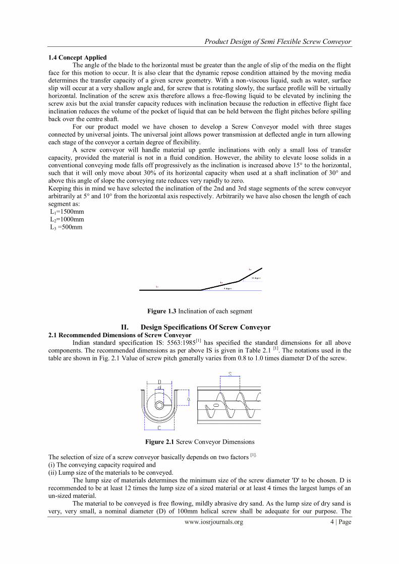
Keeping this in mind we have selected the inclination of the 2nd and 3rd stage segments of the screw conveyor
arbitrarily at 5° and 10° from the horizontal axis respectively. Arbitrarily we have also chosen the length of each
segment as:
L1=1500mm
L2=1000mm
L3 =500mm
Figure 1.3 Inclination of each segment
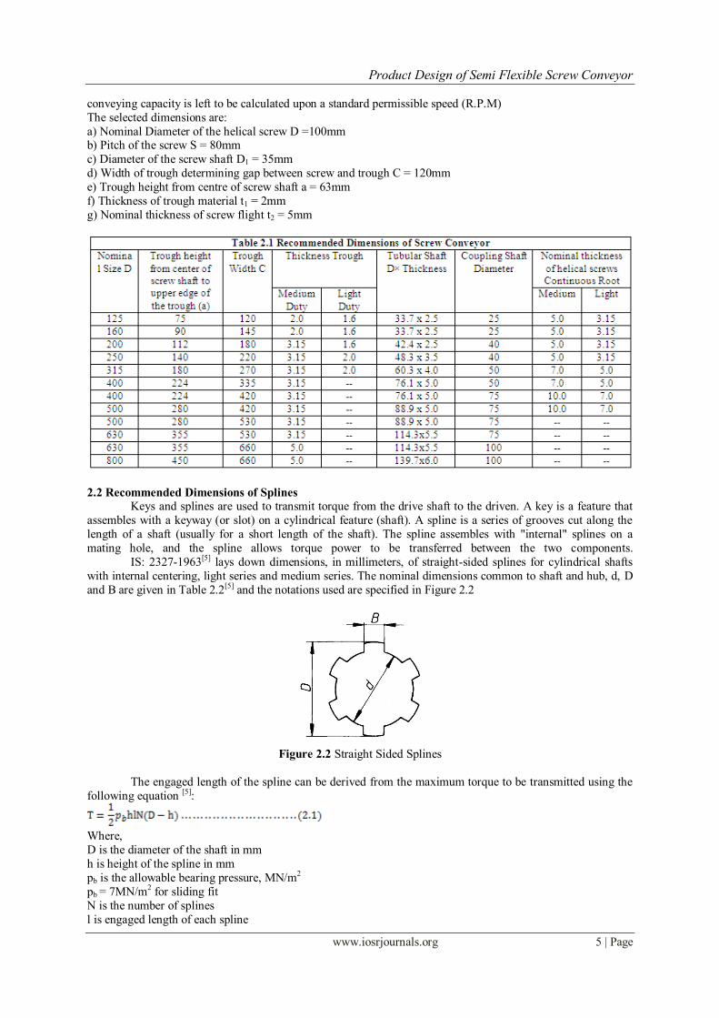
II. Design Specifications Of Screw Conveyor 2.1 Recommended Dimensions of Screw Conveyor
Indian standard specification IS: 5563:1985[1] has specified the standard dimensions for all above
components. The recommended dimensions as per above IS is given in Table 2.1 [1]. The notations used in the
table are shown in Fig. 2.1 Value of screw pitch generally varies from 0.8 to 1.0 times diameter D of the screw.
Figure 2.1 Screw Conveyor Dimensions
The selection of size of a screw conveyor basically depends on two factors [1].
(i) The conveying capacity required and
(ii) Lump size of the materials to be conveyed.
The lump size of materials determines the minimum size of the screw diameter 'D' to be chosen. D is
recommended to be at least 12 times the lump size of a sized material or at least 4 times the largest lumps of an
un-sized material.
The material to be conveyed is free flowing, mildly abrasive dry sand. As the lump size of dry sand is
very, very small, a nominal diameter (D) of 100mm helical screw shall be adequate for our purpose. The
Product Design of Semi Flexible Screw Conveyor
www.iosrjournals.org 5 | Page
conveying capacity is left to be calculated upon a standard permissible speed (R.P.M)
The selected dimensions are:
a) Nominal Diameter of the helical screw D =100mm b) Pitch of the screw S = 80mm
c) Diameter of the screw shaft D1 = 35mm
d) Width of trough determining gap between screw and trough C = 120mm
e) Trough height from centre of screw shaft a = 63mm
f) Thickness of trough material t1 = 2mm
g) Nominal thickness of screw flight t2 = 5mm
2.2 Recommended Dimensions of Splines
Keys and splines are used to transmit torque from the drive shaft to the driven. A key is a feature that
assembles with a keyway (or slot) on a cylindrical feature (shaft). A spline is a series of grooves cut along the
length of a shaft (usually for a short length of the shaft). The spline assembles with "internal" splines on a
mating hole, and the spline allows torque power to be transferred between the two components.
IS: 2327-1963[5] lays down dimensions, in millimeters, of straight-sided splines for cylindrical shafts
with internal centering, light series and medium series. The nominal dimensions common to shaft and hub, d, D
and B are given in Table 2.2[5] and the notations used are specified in Figure 2.2
Figure 2.2 Straight Sided Splines
The engaged length of the spline can be derived from the maximum torque to be transmitted using the
following equation [5]:
Where,
D is the diameter of the shaft in mm
h is height of the spline in mm
pb is the allowable bearing pressure, MN/m2
pb = 7MN/m2 for sliding fit
N is the number of splines
l is engaged length of each spline
Product Design of Semi Flexible Screw Conveyor
www.iosrjournals.org 6 | Page
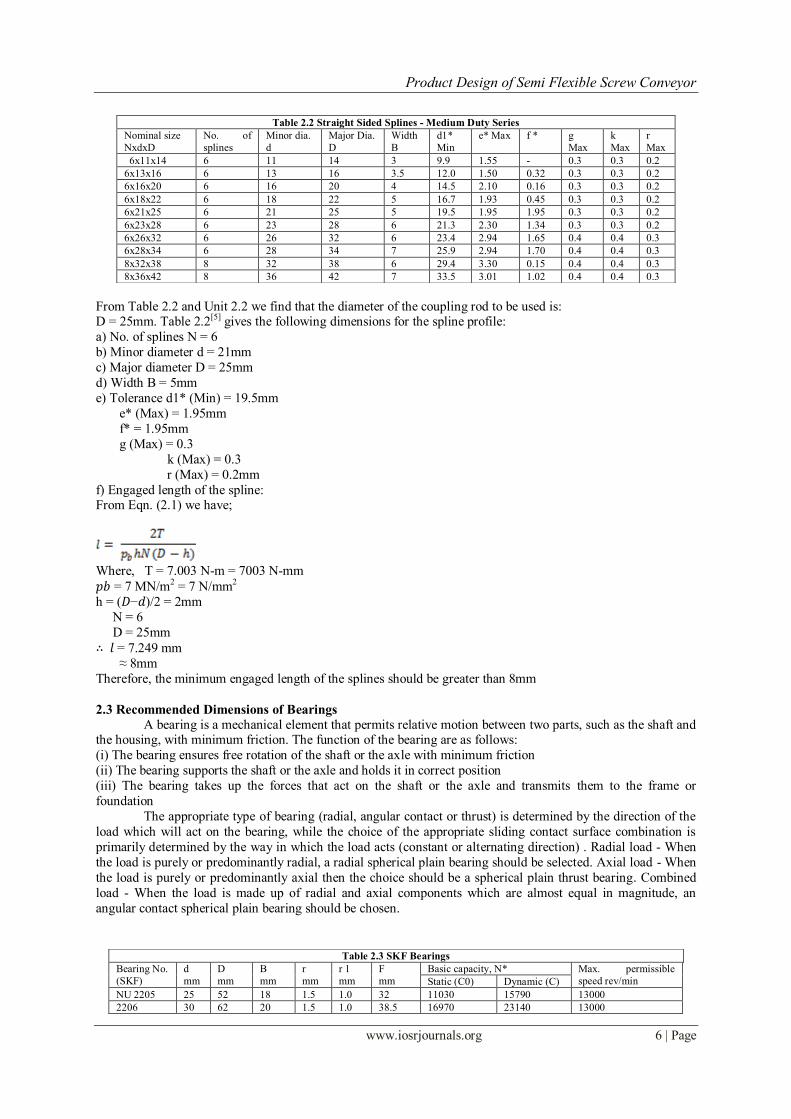
From Table 2.2 and Unit 2.2 we find that the diameter of the coupling rod to be used is: D = 25mm. Table 2.2[5] gives the following dimensions for the spline profile:
a) No. of splines N = 6
b) Minor diameter d = 21mm
c) Major diameter D = 25mm
d) Width B = 5mm
e) Tolerance d1* (Min) = 19.5mm
e* (Max) = 1.95mm
f* = 1.95mm
g (Max) = 0.3
k (Max) = 0.3
r (Max) = 0.2mm
f) Engaged length of the spline: From Eqn. (2.1) we have;
Where, T = 7.003 N-m = 7003 N-mm
𝑝𝑏 = 7 MN/m2 = 7 N/mm2
h = (𝐷−𝑑)/2 = 2mm
N = 6
D = 25mm
∴ 𝑙 = 7.249 mm
≈ 8mm
Therefore, the minimum engaged length of the splines should be greater than 8mm
2.3 Recommended Dimensions of Bearings A bearing is a mechanical element that permits relative motion between two parts, such as the shaft and
the housing, with minimum friction. The function of the bearing are as follows:
(i) The bearing ensures free rotation of the shaft or the axle with minimum friction
(ii) The bearing supports the shaft or the axle and holds it in correct position
(iii) The bearing takes up the forces that act on the shaft or the axle and transmits them to the frame or
foundation
The appropriate type of bearing (radial, angular contact or thrust) is determined by the direction of the
load which will act on the bearing, while the choice of the appropriate sliding contact surface combination is
primarily determined by the way in which the load acts (constant or alternating direction) . Radial load - When
the load is purely or predominantly radial, a radial spherical plain bearing should be selected. Axial load - When
the load is purely or predominantly axial then the choice should be a spherical plain thrust bearing. Combined
load - When the load is made up of radial and axial components which are almost equal in magnitude, an
angular contact spherical plain bearing should be chosen.
Table 2.2 Straight Sided Splines - Medium Duty Series
Nominal size
NxdxD
No. of
splines
Minor dia.
d
Major Dia.
D
Width
B
d1*
Min
e* Max f * g
Max
k
Max
r
Max
6x11x14 6 11 14 3 9.9 1.55 - 0.3 0.3 0.2
6x13x16 6 13 16 3.5 12.0 1.50 0.32 0.3 0.3 0.2
6x16x20 6 16 20 4 14.5 2.10 0.16 0.3 0.3 0.2
6x18x22 6 18 22 5 16.7 1.93 0.45 0.3 0.3 0.2
6x21x25 6 21 25 5 19.5 1.95 1.95 0.3 0.3 0.2
6x23x28 6 23 28 6 21.3 2.30 1.34 0.3 0.3 0.2
6x26x32 6 26 32 6 23.4 2.94 1.65 0.4 0.4 0.3
6x28x34 6 28 34 7 25.9 2.94 1.70 0.4 0.4 0.3
8x32x38 8 32 38 6 29.4 3.30 0.15 0.4 0.4 0.3
8x36x42 8 36 42 7 33.5 3.01 1.02 0.4 0.4 0.3
Table 2.3 SKF Bearings
Bearing No.
(SKF)
d
mm
D
mm
B
mm
r
mm
r 1
mm
F
mm
Basic capacity, N* Max. permissible
speed rev/min Static (C0) Dynamic (C)
NU 2205 25 52 18 1.5 1.0 32 11030 15790 13000
2206 30 62 20 1.5 1.0 38.5 16970 23140 13000
Product Design of Semi Flexible Screw Conveyor
www.iosrjournals.org 7 | Page
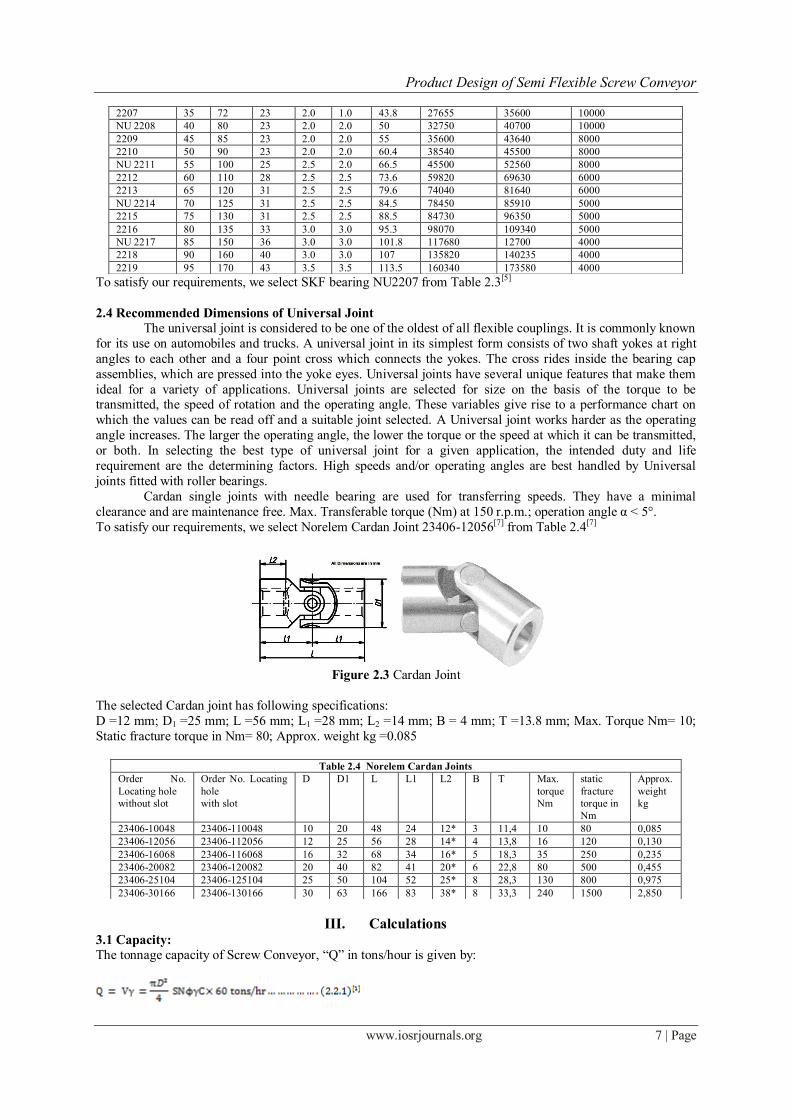
To satisfy our requirements, we select SKF bearing NU2207 from Table 2.3[5]
2.4 Recommended Dimensions of Universal Joint
The universal joint is considered to be one of the oldest of all flexible couplings. It is commonly known
for its use on automobiles and trucks. A universal joint in its simplest form consists of two shaft yokes at right
angles to each other and a four point cross which connects the yokes. The cross rides inside the bearing cap
assemblies, which are pressed into the yoke eyes. Universal joints have several unique features that make them
ideal for a variety of applications. Universal joints are selected for size on the basis of the torque to be transmitted, the speed of rotation and the operating angle. These variables give rise to a performance chart on
which the values can be read off and a suitable joint selected. A Universal joint works harder as the operating
angle increases. The larger the operating angle, the lower the torque or the speed at which it can be transmitted,
or both. In selecting the best type of universal joint for a given application, the intended duty and life
requirement are the determining factors. High speeds and/or operating angles are best handled by Universal
joints fitted with roller bearings.
Cardan single joints with needle bearing are used for transferring speeds. They have a minimal
clearance and are maintenance free. Max. Transferable torque (Nm) at 150 r.p.m.; operation angle α < 5°.
To satisfy our requirements, we select Norelem Cardan Joint 23406-12056[7] from Table 2.4[7]
Figure 2.3 Cardan Joint
The selected Cardan joint has following specifications:
D =12 mm; D1 =25 mm; L =56 mm; L1 =28 mm; L2 =14 mm; B = 4 mm; T =13.8 mm; Max. Torque Nm= 10;
Static fracture torque in Nm= 80; Approx. weight kg =0.085
III. Calculations 3.1 Capacity:
The tonnage capacity of Screw Conveyor, ―Q‖ in tons/hour is given by:
2207 35 72 23 2.0 1.0 43.8 27655 35600 10000
NU 2208 40 80 23 2.0 2.0 50 32750 40700 10000
2209 45 85 23 2.0 2.0 55 35600 43640 8000
2210 50 90 23 2.0 2.0 60.4 38540 45500 8000
NU 2211 55 100 25 2.5 2.0 66.5 45500 52560 8000
2212 60 110 28 2.5 2.5 73.6 59820 69630 6000
2213 65 120 31 2.5 2.5 79.6 74040 81640 6000
NU 2214 70 125 31 2.5 2.5 84.5 78450 85910 5000
2215 75 130 31 2.5 2.5 88.5 84730 96350 5000
2216 80 135 33 3.0 3.0 95.3 98070 109340 5000
NU 2217 85 150 36 3.0 3.0 101.8 117680 12700 4000
2218 90 160 40 3.0 3.0 107 135820 140235 4000
2219 95 170 43 3.5 3.5 113.5 160340 173580 4000
Table 2.4 Norelem Cardan Joints
Order No.
Locating hole
without slot
Order No. Locating
hole
with slot
D D1 L L1 L2 B T Max.
torque
Nm
static
fracture
torque in
Nm
Approx.
weight
kg
23406-10048 23406-110048 10 20 48 24 12* 3 11,4 10 80 0,085
23406-12056 23406-112056 12 25 56 28 14* 4 13,8 16 120 0,130
23406-16068 23406-116068 16 32 68 34 16* 5 18,3 35 250 0,235
23406-20082 23406-120082 20 40 82 41 20* 6 22,8 80 500 0,455
23406-25104 23406-125104 25 50 104 52 25* 8 28,3 130 800 0,975
23406-30166 23406-130166 30 63 166 83 38* 8 33,3 240 1500 2,850
Product Design of Semi Flexible Screw Conveyor
www.iosrjournals.org 8 | Page
Where,
V = volumetric capacity, m3 per hour
𝛾= bulk density of material, tons per m3 D = screw diameter, m
S = screw pitch, m
N = rotational speed, rpm
ϕ= loading efficiency of the vertical cross sectional area
C = factor depending on inclination of conveyor
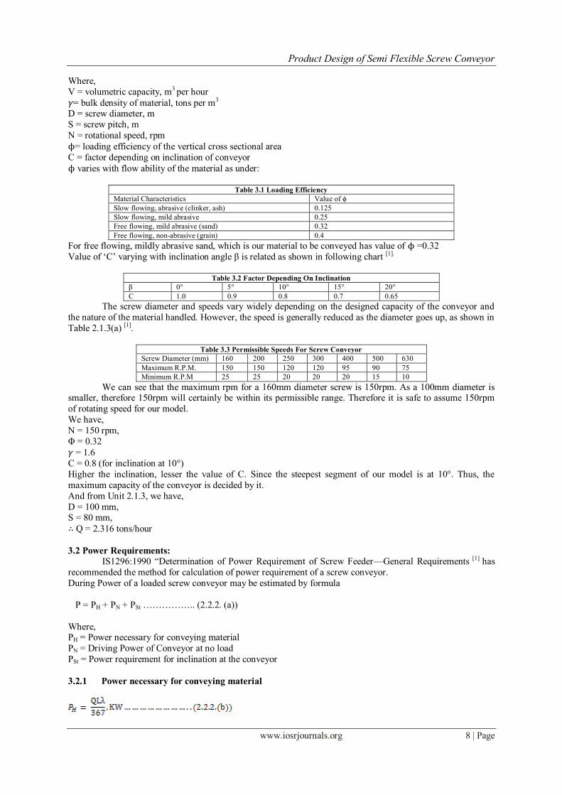
ϕ varies with flow ability of the material as under:
Table 3.1 Loading Efficiency
Material Characteristics Value of ϕ
Slow flowing, abrasive (clinker, ash) 0.125
Slow flowing, mild abrasive 0.25
Free flowing, mild abrasive (sand) 0.32
Free flowing, non-abrasive (grain) 0.4
For free flowing, mildly abrasive sand, which is our material to be conveyed has value of ϕ =0.32
Value of ‗C‘ varying with inclination angle β is related as shown in following chart [1].
Table 3.2 Factor Depending On Inclination
β 0° 5° 10° 15° 20°
C 1.0 0.9 0.8 0.7 0.65
The screw diameter and speeds vary widely depending on the designed capacity of the conveyor and
the nature of the material handled. However, the speed is generally reduced as the diameter goes up, as shown in
Table 2.1.3(a) [1].
Table 3.3 Permissible Speeds For Screw Conveyor
Screw Diameter (mm) 160 200 250 300 400 500 630
Maximum R.P.M. 150 150 120 120 95 90 75
Minimum R.P.M 25 25 20 20 20 15 10
We can see that the maximum rpm for a 160mm diameter screw is 150rpm. As a 100mm diameter is smaller, therefore 150rpm will certainly be within its permissible range. Therefore it is safe to assume 150rpm
of rotating speed for our model.
We have,
N = 150 rpm,
Φ = 0.32
𝛾 = 1.6
C = 0.8 (for inclination at 10°)
Higher the inclination, lesser the value of C. Since the steepest segment of our model is at 10°. Thus, the
maximum capacity of the conveyor is decided by it.
And from Unit 2.1.3, we have,
D = 100 mm, S = 80 mm,
∴ Q = 2.316 tons/hour
3.2 Power Requirements:
IS1296:1990 ―Determination of Power Requirement of Screw Feeder—General Requirements [1] has
recommended the method for calculation of power requirement of a screw conveyor.
During Power of a loaded screw conveyor may be estimated by formula
P = PH + PN + PSt …………….. (2.2.2. (a))
Where, PH = Power necessary for conveying material
PN = Driving Power of Conveyor at no load
PSt = Power requirement for inclination at the conveyor
3.2.1 Power necessary for conveying material
Product Design of Semi Flexible Screw Conveyor
www.iosrjournals.org 9 | Page
Where,
Q = Mass flow rate in tonnes/hour
L = Length of material movement in conveyor in m
𝜆 = Progress resistance coefficient (friction coefficient)
= 4 for sand.
3.2.2 Drive power at no load:
PN is proportional to the screw diameter and total length of the screw.
Where,
D = Nominal Screw diameter, m
L = Length of Screw, m
3.2.3 Power requirement for inclination at the conveyor:
PSt is the product of the mass flow rate and height to which the material is being conveyed.
Where,
Q = Mass flow rate in tonnes/hour
H = Height of the inclination in m
I. Considering First Body of Screw Conveyor at 0 Degree Inclination:
Here,
Q = 2.316 tons/hour,
L = 1.5 m,
𝜆 = Progress resistance coefficient (friction coefficient)
= 4 for sand. ∴ PH = 0.0378 KW
And,
D = 100 mm, = 0.1 m L = 1.5 m.
∴ PN = 7.5 × 10⁻³ KW
∴ Power needed for First Screw Conveyor Body P1 = PH+ PN
= 0.0453 KW
II. Considering Second Body of Screw Conveyor at 5 Degree Inclination:
Here,
Q = 2.316 tons/hr.
L = 1 m,
𝜆 = Progress resistance coefficient (friction coefficient)
= 4 for sand. ∴ PH = 0.0252 KW
And, D = 100mm = 0.1 m,
L = 1m,
∴ PN = 5 × 10⁻³ KW
And,
Q = 2.316 tons/hour,
H = L×Cos (5°)
∴ PSt = 6.286 × 10⁻³ KW
∴ Power needed for Second Screw Conveyor Body
P = PH + PN + PSt
= 0.0362 KW
III. Considering Third Body of Screw Conveyor at 10 Degree Inclination:
Here,
Q = 2.316 tons/hr.
L = 0.5 m,
𝜆 = Progress resistance coefficient (friction coefficient)
= 4 for sand. ∴ PH = 0.0126 KW
Product Design of Semi Flexible Screw Conveyor
www.iosrjournals.org 10 | Page
And,
D = 100 mm = 0.1 m,
L = 0.5 m, ∴ PN = 2.5 × 10⁻³ KW
And, Q = 2.316 tons/hr.
H = L× Cos (10°)
∴ PSt = 3.107 × 10⁻³ KW
∴ Power needed for Third Screw Conveyor Body
P = PH + PN + PSt
= 0.0182 KW
Total Power Required,
P = 𝑃1+ 𝑃2+ 𝑃3
= 0.0997 KW
≈ 0.1 KW≈100 𝑤𝑎𝑡𝑡 This gives us the minimum power needed to rotate the screw conveyor at max load condition. Only a
motor of power 100 watts or higher can be used to power this screw conveyor..
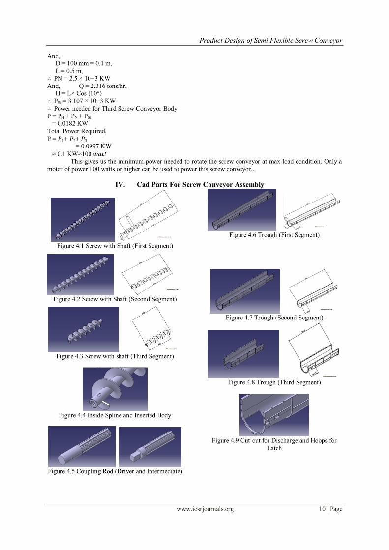
IV. Cad Parts For Screw Conveyor Assembly
Figure 4.1 Screw with Shaft (First Segment)
Figure 4.2 Screw with Shaft (Second Segment)
Figure 4.3 Screw with shaft (Third Segment)
Figure 4.4 Inside Spline and Inserted Body
Figure 4.5 Coupling Rod (Driver and Intermediate)
Figure 4.6 Trough (First Segment)
Figure 4.7 Trough (Second Segment)
Figure 4.8 Trough (Third Segment)
Figure 4.9 Cut-out for Discharge and Hoops for
Latch
Product Design of Semi Flexible Screw Conveyor
www.iosrjournals.org 11 | Page
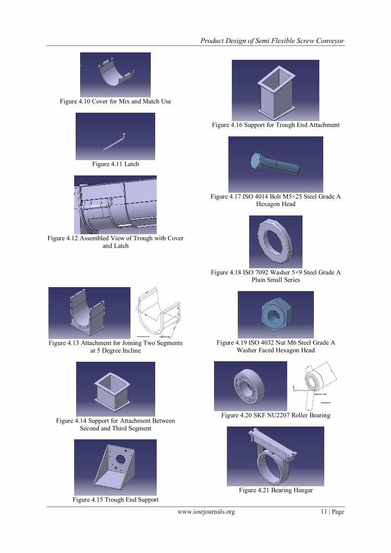
Figure 4.10 Cover for Mix and Match Use
Figure 4.11 Latch
Figure 4.12 Assembled View of Trough with Cover
and Latch
Figure 4.13 Attachment for Joining Two Segments
at 5 Degree Incline
Figure 4.14 Support for Attachment Between
Second and Third Segment
Figure 4.15 Trough End Support
Figure 4.16 Support for Trough End Attachment
Figure 4.17 ISO 4014 Bolt M5×25 Steel Grade A
Hexagon Head
Figure 4.18 ISO 7092 Washer 5×9 Steel Grade A
Plain Small Series
Figure 4.19 ISO 4032 Nut M6 Steel Grade A
Washer Faced Hexagon Head
Figure 4.20 SKF NU2207 Roller Bearing
Figure 4.21 Bearing Hangar
Product Design of Semi Flexible Screw Conveyor
www.iosrjournals.org 12 | Page
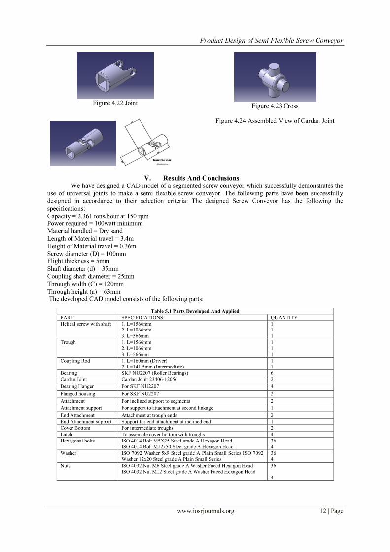
Figure 4.22 Joint
Figure 4.23 Cross
Figure 4.24 Assembled View of Cardan Joint
V. Results And Conclusions We have designed a CAD model of a segmented screw conveyor which successfully demonstrates the
use of universal joints to make a semi flexible screw conveyor. The following parts have been successfully
designed in accordance to their selection criteria: The designed Screw Conveyor has the following the
specifications:
Capacity = 2.361 tons/hour at 150 rpm
Power required = 100watt minimum Material handled = Dry sand
Length of Material travel = 3.4m
Height of Material travel = 0.36m
Screw diameter (D) = 100mm
Flight thickness = 5mm
Shaft diameter (d) = 35mm
Coupling shaft diameter = 25mm
Through width (C) = 120mm
Through height (a) = 63mm
The developed CAD model consists of the following parts:
Table 5.1 Parts Developed And Applied
PART SPECIFICATIONS QUANTITY
Helical screw with shaft 1. L=1566mm
2. L=1066mm
3. L=566mm
1
1
1
Trough 1. L=1566mm
2. L=1066mm
3. L=566mm
1
1
1
Coupling Rod 1. L=160mm (Driver)
2. L=141.5mm (Intermediate)
1
1
Bearing SKF NU2207 (Roller Bearings) 6
Cardan Joint Cardan Joint 23406-12056 2
Bearing Hanger For SKF NU2207 4
Flanged housing For SKF NU2207 2
Attachment For inclined support to segments 2
Attachment support For support to attachment at second linkage 1
End Attachment Attachment at trough ends 2
End Attachment support Support for end attachment at inclined end 1
Cover Bottom For intermediate troughs 2
Latch To assemble cover bottom with troughs 4
Hexagonal bolts ISO 4014 Bolt M5X25 Steel grade A Hexagon Head
ISO 4014 Bolt M12x50 Steel grade A Hexagon Head
36
4
Washer ISO 7092 Washer 5x9 Steel grade A Plain Small Series ISO 7092
Washer 12x20 Steel grade A Plain Small Series
36
4
Nuts ISO 4032 Nut M6 Steel grade A Washer Faced Hexagon Head
ISO 4032 Nut M12 Steel grade A Washer Faced Hexagon Head
36
4
Product Design of Semi Flexible Screw Conveyor
www.iosrjournals.org 13 | Page
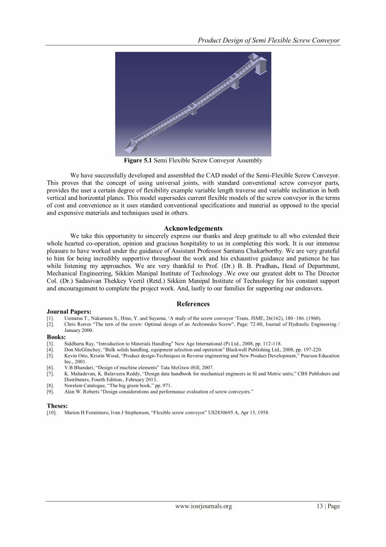
Figure 5.1 Semi Flexible Screw Conveyor Assembly
We have successfully developed and assembled the CAD model of the Semi-Flexible Screw Conveyor.
This proves that the concept of using universal joints, with standard conventional screw conveyor parts,
provides the user a certain degree of flexibility example variable length traverse and variable inclination in both
vertical and horizontal planes. This model supersedes current flexible models of the screw conveyor in the terms
of cost and convenience as it uses standard conventional specifications and material as opposed to the special
and expensive materials and techniques used in others.
Acknowledgements We take this opportunity to sincerely express our thanks and deep gratitude to all who extended their
whole hearted co-operation, opinion and gracious hospitality to us in completing this work. It is our immense
pleasure to have worked under the guidance of Assistant Professor Santanu Chakarborthy. We are very grateful
to him for being incredibly supportive throughout the work and his exhaustive guidance and patience he has
while listening my approaches. We are very thankful to Prof. (Dr.) B. B. Pradhan, Head of Department,
Mechanical Engineering, Sikkim Manipal Institute of Technology .We owe our greatest debt to The Director
Col. (Dr.) Sadasivan Thekkey Veetil (Retd.) Sikkim Manipal Institute of Technology for his constant support
and encouragement to complete the project work. And, lastly to our families for supporting our endeavors.
References Journal Papers: [1]. Uematsu T., Nakamura S., Hino, Y. and Suyama, ‗A study of the screw conveyor ‗Trans. JSME, 26(162), 180–186. (1960).
[2]. Chris Rorres ―The turn of the screw: Optimal design of an Archimedes Screw‖, Page: 72-80, Journal of Hydraulic Engineering /
January 2000.
Books: [3]. Siddharta Ray, ―Introduction to Materials Handling‖ New Age International (P) Ltd., 2008, pp. 112-118.
[4]. Don McGlinchey, ―Bulk solids handling, equipment selection and operation‖ Blackwell Publishing Ltd., 2008, pp. 197-220.
[5]. Kevin Otto, Kristin Wood, ―Product design-Techniques in Reverse engineering and New Product Development,‖ Pearson Education
Inc., 2001.
[6]. V.B Bhandari, ―Design of machine elements‖ Tata McGraw-Hill, 2007.
[7]. K. Mahadevan, K. Balaveera Reddy, ―Design data handbook for mechanical engineers in SI and Metric units,‖ CBS Publishers and
Distributers, Fourth Edition., February 2013.
[8]. Norelem Catalogue, ―The big green book,‖ pp. 971.
[9]. Alan W. Roberts ―Design considerations and performance evaluation of screw conveyors.‖
Theses: [10]. Marion H Fennimore, Ivan J Stephenson, ―Flexible screw conveyor‖ US2830695 A, Apr 15, 1958.