process device manager simatic pdm -...
TRANSCRIPT
SIMATIC PCS 7
SIMATIC PDM Process Device Manager
Answers for industry.
BrochureNovember2012
Umschlag_Br_PDM_2012_en.indd 3 09.11.2012 15:11:00
© Siemens AG 2012
SIMATIC PDM Process Device Manager2
SIMATIC PDM Process Device ManagerOverview
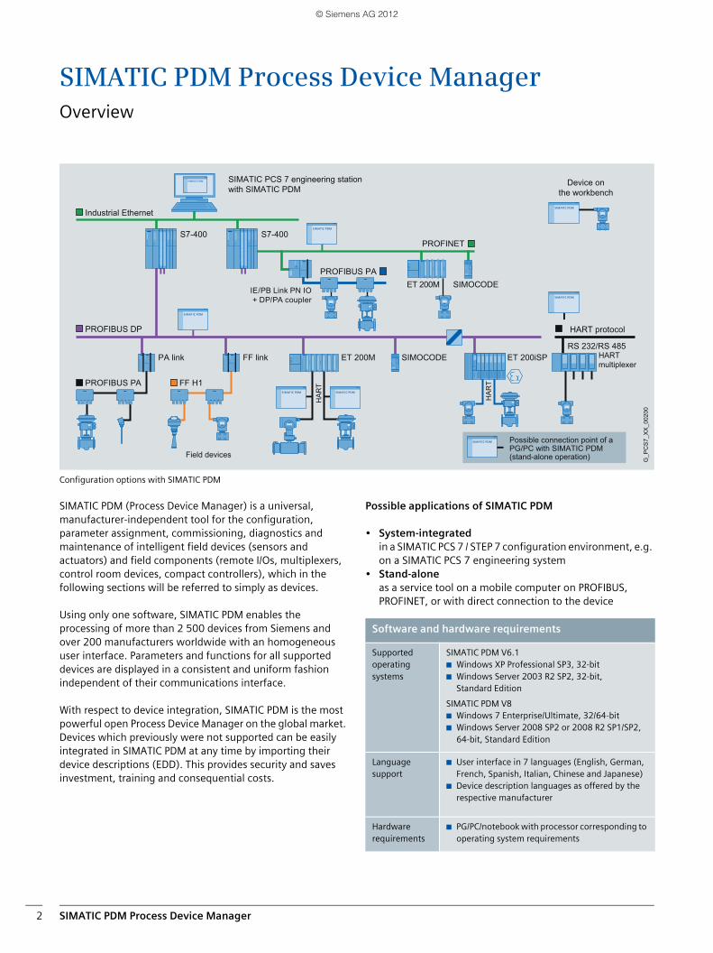
Configuration options with SIMATIC PDM
SIMATIC PDM (Process Device Manager) is a universal, manufacturer-independent tool for the configuration, parameter assignment, commissioning, diagnostics and maintenance of intelligent field devices (sensors and actuators) and field components (remote I/Os, multiplexers, control room devices, compact controllers), which in the following sections will be referred to simply as devices.
Using only one software, SIMATIC PDM enables the processing of more than 2 500 devices from Siemens and over 200 manufacturers worldwide with an homogeneous user interface. Parameters and functions for all supported devices are displayed in a consistent and uniform fashion independent of their communications interface.
With respect to device integration, SIMATIC PDM is the most powerful open Process Device Manager on the global market. Devices which previously were not supported can be easily integrated in SIMATIC PDM at any time by importing their device descriptions (EDD). This provides security and saves investment, training and consequential costs.
Possible applications of SIMATIC PDM
• System-integrated in a SIMATIC PCS 7 / STEP 7 configuration environment, e.g. on a SIMATIC PCS 7 engineering system
• Stand-alone as a service tool on a mobile computer on PROFIBUS, PROFINET, or with direct connection to the device
PROFIBUS PA FF H1
SIMOCODE
SIMOCODE
ET 200iSP
S7-400S7-400
HA
RT
HA
RT
G_P
CS
7_X
X_0
0200
RS 232/RS 485
PROFIBUS DP
Industrial Ethernet
PROFINET
PROFIBUS PA
ET 200M
ET 200M
PA link FF link
SIMATIC PCS 7 engineering stationwith SIMATIC PDM
Possible connection point of a PG/PC with SIMATIC PDM(stand-alone operation)
HARTmultiplexer
Device onthe workbench
HART protocol
IE/PB Link PN IO + DP/PA coupler
Field devices
Software and hardware requirements
Supported operating systems
SIMATIC PDM V6.1■ Windows XP Professional SP3, 32-bit■ Windows Server 2003 R2 SP2, 32-bit,
Standard Edition
SIMATIC PDM V8■ Windows 7 Enterprise/Ultimate, 32/64-bit ■ Windows Server 2008 SP2 or 2008 R2 SP1/SP2,
64-bit, Standard Edition
Language support
■ User interface in 7 languages (English, German, French, Spanish, Italian, Chinese and Japanese)
■ Device description languages as offered by the respective manufacturer
Hardware requirements
■ PG/PC/notebook with processor corresponding to operating system requirements
© Siemens AG 2012
SIMATIC PDM Process Device Manager 3
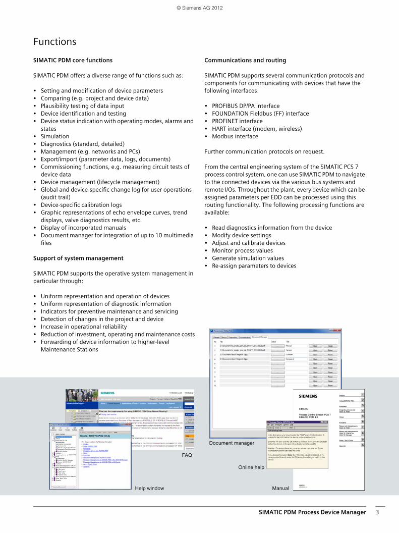
Help window
Document manager
FAQ
Online help
Manual
Functions
SIMATIC PDM core functions
SIMATIC PDM offers a diverse range of functions such as:
• Setting and modification of device parameters• Comparing (e.g. project and device data)• Plausibility testing of data input• Device identification and testing• Device status indication with operating modes, alarms and
states• Simulation• Diagnostics (standard, detailed)• Management (e.g. networks and PCs)• Export/import (parameter data, logs, documents)• Commissioning functions, e.g. measuring circuit tests of
device data• Device management (lifecycle management)• Global and device-specific change log for user operations
(audit trail)• Device-specific calibration logs• Graphic representations of echo envelope curves, trend
displays, valve diagnostics results, etc.• Display of incorporated manuals• Document manager for integration of up to 10 multimedia
files
Support of system management
SIMATIC PDM supports the operative system management in particular through:
• Uniform representation and operation of devices• Uniform representation of diagnostic information• Indicators for preventive maintenance and servicing• Detection of changes in the project and device• Increase in operational reliability• Reduction of investment, operating and maintenance costs• Forwarding of device information to higher-level
Maintenance Stations
Communications and routing
SIMATIC PDM supports several communication protocols and components for communicating with devices that have the following interfaces:
• PROFIBUS DP/PA interface• FOUNDATION Fieldbus (FF) interface• PROFINET interface• HART interface (modem, wireless)• Modbus interface
Further communication protocols on request.
From the central engineering system of the SIMATIC PCS 7 process control system, one can use SIMATIC PDM to navigate to the connected devices via the various bus systems and remote I/Os. Throughout the plant, every device which can be assigned parameters per EDD can be processed using this routing functionality. The following processing functions are available:
• Read diagnostics information from the device• Modify device settings• Adjust and calibrate devices• Monitor process values• Generate simulation values• Re-assign parameters to devices
© Siemens AG 2012
Engineering4
EngineeringClearly structured engineering with coordinated views
The ergonomic operator interface of SIMATIC PDM satisfies the requirements of the guidelines VDI/VDE GMA 2187 and IEC 65/349/CD. Even complex devices with several hundred parameters can be represented clearly and processed quickly. Expansion of the device description language EDDL also allows display elements to be shown perfectly.
Operators are provided with several views of the project and the devices to be processed, and their application depends on the procedure and mode of use of the Process Device Manager (stand-alone or integrated in STEP 7/SIMATIC PCS 7):
• Hardware project view for the SIMATIC PDM integrated in SIMATIC PCS 7/STEP 7View of SIMATIC PCS 7/S7 hardware project from which the SIMATIC PDM parameter assignment user interface can be directly opened for the devices; devices are configured using HW Config and displayed graphically or in tabular form.
• Process device network view, preferably for stand-alone useProject view for clear representation of the hierarchical hardware structure with all networks, communications components, and devices. This can be automatically produced by scanning the actual plant. The parameter data gained in the stand-alone version of SIMATIC PDM can be imported into a SIMATIC PCS 7/S7 project.
• Process device plant viewView of all devices/TAGs present in the project (independent of the communications path used) with additional information on the diagnostics state of the devices and communications paths. Uniform symbols are used to display the diagnostics state of all devices.
• Parameter view View of device parameters with a wide variety of functions:- Parameter assignment functions, e.g. measurement
unit, measuring range- Online functions, e.g. display values, charts, diagnostics- Calibration functions, e.g. zero, runtimes of valves- Comparison functions, e.g. devices, saved project data- Export/import functions, e.g. parameters, projects- Logging functions
• Lifelist view for commissioning and service Single or cyclically generated network view for the identification and addressing of devices
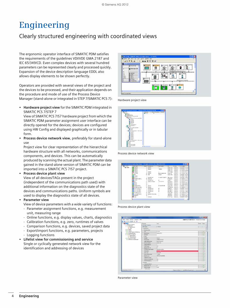
Hardware project view
Process device network view
Process device plant view
Parameter view
© Siemens AG 2012
Device integration 5
Device integrationDevice integration made easy
Electronic Device Description (EDD)
SIMATIC PDM supports all devices which are defined by means of the Electronic Device Description (EDD). EDD is standar-dized to EN 50391 and IEC 61804. Internationally, it is the most widely used standardized technology for device integ-ration. At the same time, it is the guideline of the established organizations for
• PROFIBUS and PROFINET (PI - PROFIBUS & PROFINET International)
• HART (HCF: HART Communication Foundation)• FF (Fieldbus Foundation)
The devices are integrated directly in SIMATIC PDM through a company-specific EDD, or the current HCF or Fieldbus Foundation libraries.
PROFIBUS devices are described in the EDD in terms of functio-nality and construction using the Electronic Device Description Language (EDDL). Using this description, SIMATIC PDM automatically creates its user interface with the specific device information. The range of devices can be updated and expanded by simply importing the manufac-turer's device-specific EDD.
Fieldbus Foundation provides pre-defined device descriptions (standard DD) for the basic functions of specific field device types. The basic functions are implemented using various standard function and transmission blocks.
The current device description library of SIMATIC PDM covers more than 2 500 devices from over 200 manufacturers world-wide. By simply importing the manufacturer's device-specific EDD, existing devices can be updated and further devices can be integrated in SIMATIC PDM. It is thus possible to keep the device range up to date at all times and to add to the number of manufacturers and devices supported by SIMATIC PDM.
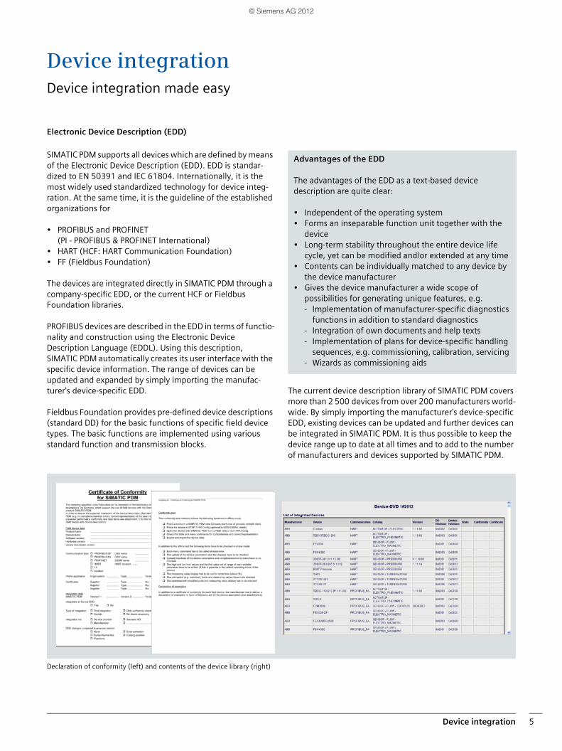
Declaration of conformity (left) and contents of the device library (right)
Advantages of the EDD
The advantages of the EDD as a text-based device description are quite clear:
• Independent of the operating system • Forms an inseparable function unit together with the
device • Long-term stability throughout the entire device life
cycle, yet can be modified and/or extended at any time • Contents can be individually matched to any device by
the device manufacturer • Gives the device manufacturer a wide scope of
possibilities for generating unique features, e.g. - Implementation of manufacturer-specific diagnostics
functions in addition to standard diagnostics - Integration of own documents and help texts - Implementation of plans for device-specific handling
sequences, e.g. commissioning, calibration, servicing - Wizards as commissioning aids
© Siemens AG 2012
Device integration6
Device integration
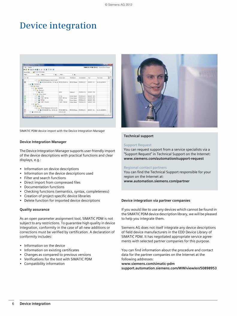
SIMATIC PDM device import with the Device Integration Manager
Device Integration Manager
The Device Integration Manager supports user-friendly import of the device descriptions with practical functions and clear displays, e.g.:
• Information on device descriptions• Information on the device descriptions used• Filter and search functions • Direct import from compressed files• Documentation functions• Checking functions (semantics, syntax, completeness)• Creation of project-specific device libraries• Delete function for imported device descriptions
Quality assurance
As an open parameter assignment tool, SIMATIC PDM is not subject to any restrictions. To guarantee high quality in device integration, conformity in the case of all new additions or corrections must be verified by certification. A declaration of conformity includes:
• Information on the device• Information on existing certificates• Changes as compared to previous versions• Verifications for the test with SIMATIC PDM• Compatibility information
Device integration via partner companies
If you would like to use any devices which cannot be found in the SIMATIC PDM device description library, we will be pleased to help you integrate them.
Siemens AG does not itself integrate any device descriptions of field device manufacturers in the EDD Device Library of SIMATIC PDM. It has negotiated appropriate service agree-ments with selected partner companies for this purpose.
You can find information about the procedure and contact data for the partner companies on the Internet at the following addresses: www.siemens.com/simatic-pdmsupport.automation.siemens.com/WW/view/en/50898953
Technical support
Support Request You can request support from a service specialists via a "Support Request" in Technical Support on the Internet:www.siemens.com/automation/support-request
Regional contact partners You can find the Technical Support responsible for your region on the Internet at:www.automation.siemens.com/partner
© Siemens AG 2012
Parameter view 7
Parameter viewCentral device view with uniform representation
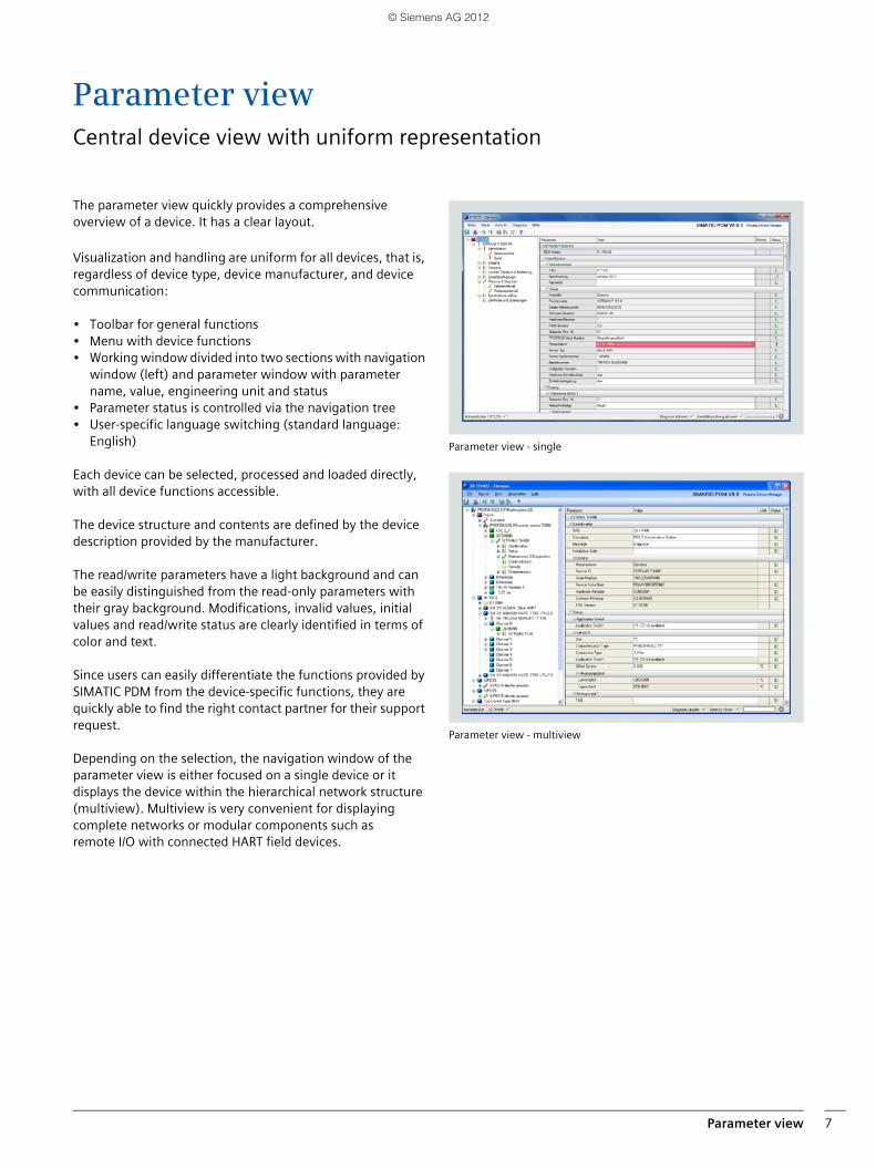
The parameter view quickly provides a comprehensive overview of a device. It has a clear layout.
Visualization and handling are uniform for all devices, that is, regardless of device type, device manufacturer, and device communication:
• Toolbar for general functions • Menu with device functions • Working window divided into two sections with navigation
window (left) and parameter window with parameter name, value, engineering unit and status
• Parameter status is controlled via the navigation tree• User-specific language switching (standard language:
English)
Each device can be selected, processed and loaded directly, with all device functions accessible.
The device structure and contents are defined by the device description provided by the manufacturer.
The read/write parameters have a light background and can be easily distinguished from the read-only parameters with their gray background. Modifications, invalid values, initial values and read/write status are clearly identified in terms of color and text.
Since users can easily differentiate the functions provided by SIMATIC PDM from the device-specific functions, they are quickly able to find the right contact partner for their support request.
Depending on the selection, the navigation window of the parameter view is either focused on a single device or it displays the device within the hierarchical network structure (multiview). Multiview is very convenient for displaying complete networks or modular components such as remote I/O with connected HART field devices.
Parameter view - single
Parameter view - multiview
© Siemens AG 2012
Informative online displays8
Informative online displays
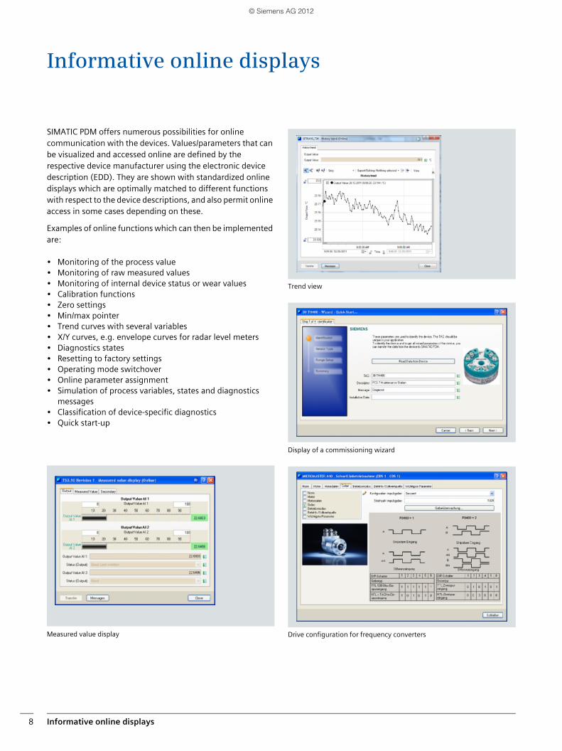
SIMATIC PDM offers numerous possibilities for online communication with the devices. Values/parameters that can be visualized and accessed online are defined by the respective device manufacturer using the electronic device description (EDD). They are shown with standardized online displays which are optimally matched to different functions with respect to the device descriptions, and also permit online access in some cases depending on these.
Examples of online functions which can then be implemented are:
• Monitoring of the process value• Monitoring of raw measured values• Monitoring of internal device status or wear values• Calibration functions• Zero settings• Min/max pointer• Trend curves with several variables• X/Y curves, e.g. envelope curves for radar level meters• Diagnostics states• Resetting to factory settings• Operating mode switchover• Online parameter assignment• Simulation of process variables, states and diagnostics
messages• Classification of device-specific diagnostics• Quick start-up
Measured value display
Trend view
Display of a commissioning wizard
Drive configuration for frequency converters
© Siemens AG 2012
Device management 9
Device management
Essential criteria for the use of intelligent field devices include:
• Simple and efficient engineering
• Stable device descriptions across the entire life cycle of the production plant/device
The device types, versions, and manufacturers used in production plants are often not yet known at the time of planning and configuration. Moreover, commissioning, maintenance, service, and device replacement must be as easy and problem-free as possible for the plant personnel. With device-neutral configuration and different device management scenarios, SIMATIC PDM is able to meet these challenges.
Device-neutral configuration
In device-neutral configuration of process tags, it is not necessary to know the precise device type or the manufac-turer of the field device. A typical example of this is the
connection of HART field devices on 4 - 20 mA interfaces of HART-enabled analog modules in remote I/O stations. On these 4 - 20 mA interfaces, any field devices with a suitable interface can be connected and operated via a "neutral channel".
The configuration of the process tag in the automation project takes place distinctly from the field device used later. Using SIMATIC PDM, a device-neutral device description containing only the process tag data, for example, can be assigned for the period up to commissioning. However, to be able to use the full device functionality, device-specific parameter assignment cannot be avoided. For this purpose, a device-specific EDD is simply assigned with SIMATIC PDM.
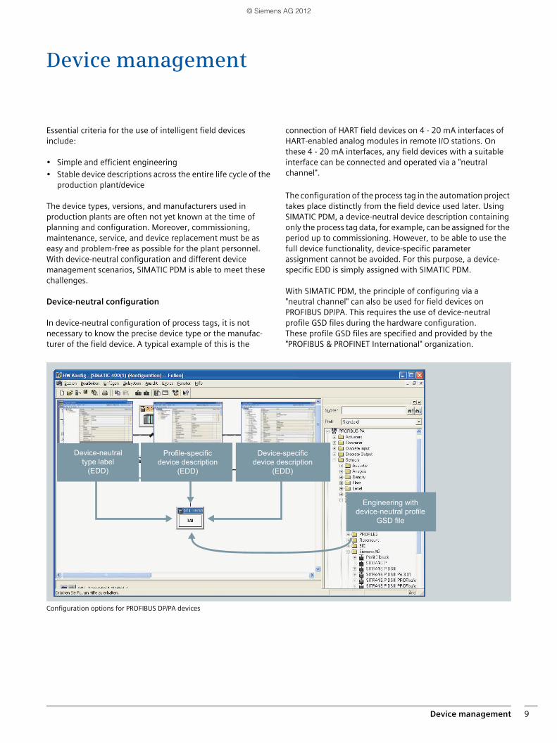
With SIMATIC PDM, the principle of configuring via a "neutral channel" can also be used for field devices on PROFIBUS DP/PA. This requires the use of device-neutral profile GSD files during the hardware configuration. These profile GSD files are specified and provided by the "PROFIBUS & PROFINET International" organization.
Configuration options for PROFIBUS DP/PA devices
Device-neutral type label
(EDD)
Profile-specific device description
(EDD)
Device-specific device description
(EDD)
Engineering with device-neutral profile
GSD file
© Siemens AG 2012
Device management10
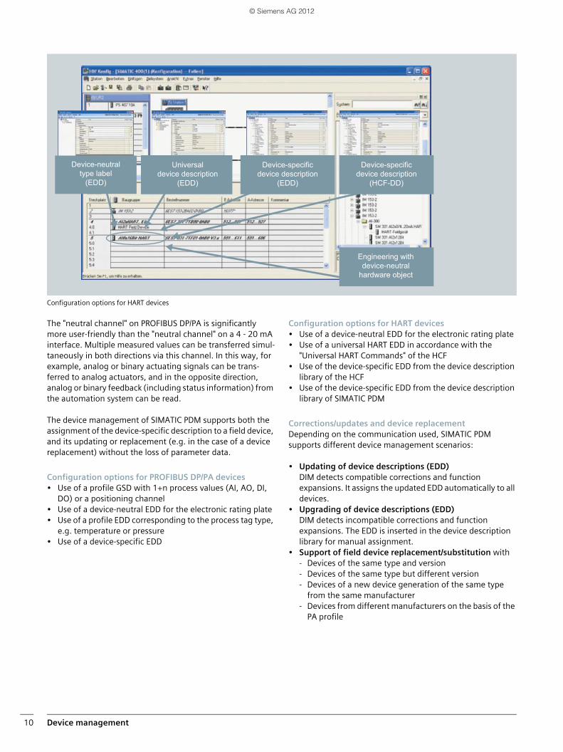
Configuration options for HART devices
The "neutral channel" on PROFIBUS DP/PA is significantly more user-friendly than the "neutral channel" on a 4 - 20 mA interface. Multiple measured values can be transferred simul-taneously in both directions via this channel. In this way, for example, analog or binary actuating signals can be trans-ferred to analog actuators, and in the opposite direction, analog or binary feedback (including status information) from the automation system can be read.
The device management of SIMATIC PDM supports both the assignment of the device-specific description to a field device, and its updating or replacement (e.g. in the case of a device replacement) without the loss of parameter data.
Configuration options for PROFIBUS DP/PA devices• Use of a profile GSD with 1+n process values (AI, AO, DI,
DO) or a positioning channel• Use of a device-neutral EDD for the electronic rating plate • Use of a profile EDD corresponding to the process tag type,
e.g. temperature or pressure• Use of a device-specific EDD
Configuration options for HART devices• Use of a device-neutral EDD for the electronic rating plate • Use of a universal HART EDD in accordance with the
"Universal HART Commands" of the HCF• Use of the device-specific EDD from the device description
library of the HCF• Use of the device-specific EDD from the device description
library of SIMATIC PDM
Corrections/updates and device replacementDepending on the communication used, SIMATIC PDM supports different device management scenarios:
• Updating of device descriptions (EDD)DIM detects compatible corrections and function expansions. It assigns the updated EDD automatically to all devices.
• Upgrading of device descriptions (EDD)DIM detects incompatible corrections and function expansions. The EDD is inserted in the device description library for manual assignment.
• Support of field device replacement/substitution with- Devices of the same type and version- Devices of the same type but different version- Devices of a new device generation of the same type
from the same manufacturer- Devices from different manufacturers on the basis of the
PA profile
Device-neutral type label
(EDD)
Universal device description
(EDD)
Device-specific device description
(EDD)
Device-specific device description
(HCF-DD)
Engineering with device-neutral
hardware object
© Siemens AG 2012
Lifelist 11
Lifelist
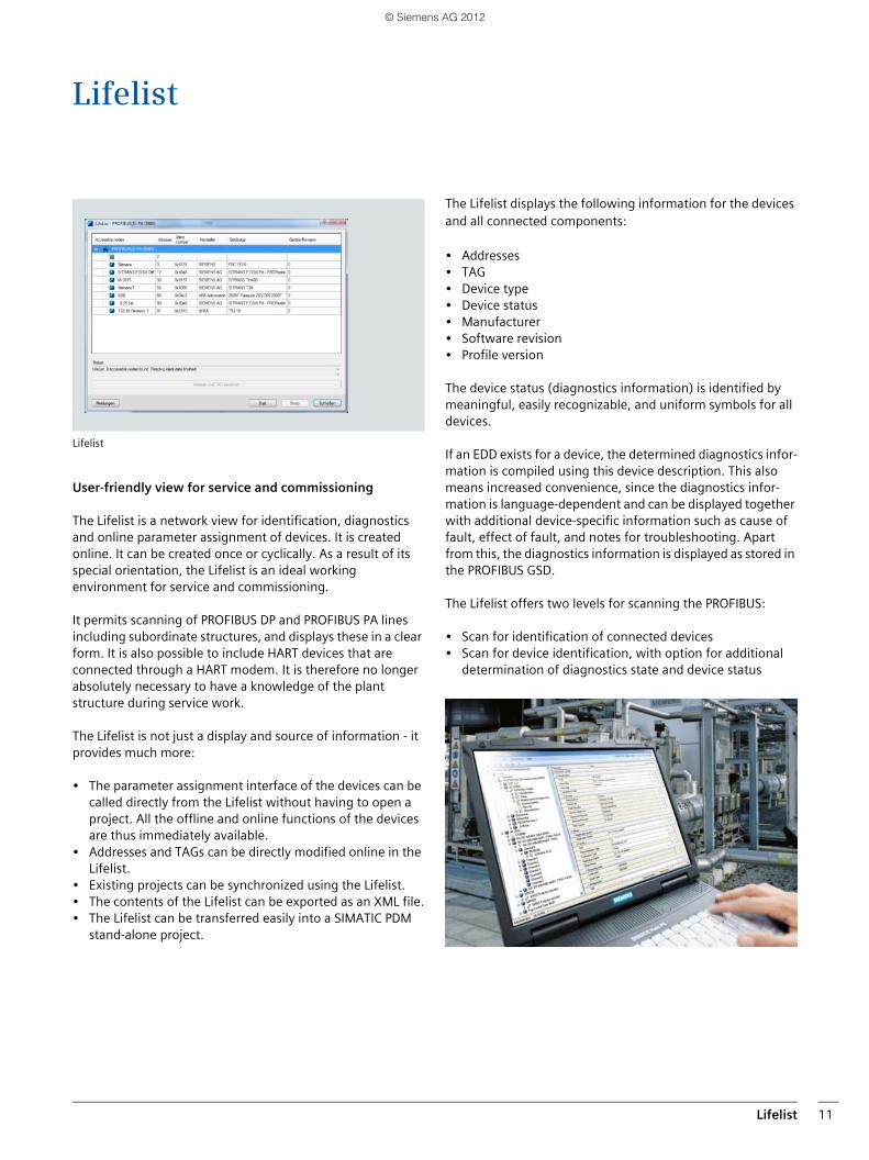
Lifelist
User-friendly view for service and commissioning
The Lifelist is a network view for identification, diagnostics and online parameter assignment of devices. It is created online. It can be created once or cyclically. As a result of its special orientation, the Lifelist is an ideal working environment for service and commissioning.
It permits scanning of PROFIBUS DP and PROFIBUS PA lines including subordinate structures, and displays these in a clear form. It is also possible to include HART devices that are connected through a HART modem. It is therefore no longer absolutely necessary to have a knowledge of the plant structure during service work.
The Lifelist is not just a display and source of information - it provides much more:
• The parameter assignment interface of the devices can be called directly from the Lifelist without having to open a project. All the offline and online functions of the devices are thus immediately available.
• Addresses and TAGs can be directly modified online in the Lifelist.
• Existing projects can be synchronized using the Lifelist.• The contents of the Lifelist can be exported as an XML file.• The Lifelist can be transferred easily into a SIMATIC PDM
stand-alone project.
The Lifelist displays the following information for the devices and all connected components:
• Addresses• TAG• Device type• Device status• Manufacturer• Software revision• Profile version
The device status (diagnostics information) is identified by meaningful, easily recognizable, and uniform symbols for all devices.
If an EDD exists for a device, the determined diagnostics infor-mation is compiled using this device description. This also means increased convenience, since the diagnostics infor-mation is language-dependent and can be displayed together with additional device-specific information such as cause of fault, effect of fault, and notes for troubleshooting. Apart from this, the diagnostics information is displayed as stored in the PROFIBUS GSD.
The Lifelist offers two levels for scanning the PROFIBUS:
• Scan for identification of connected devices• Scan for device identification, with option for additional
determination of diagnostics state and device status
© Siemens AG 2012
HART OPC server12
HART OPC serverRecording of structures of HART multiplexer networks
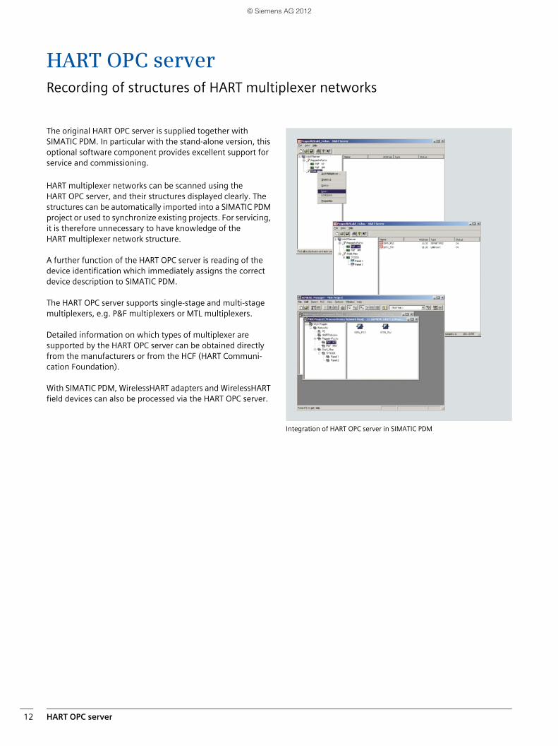
The original HART OPC server is supplied together with SIMATIC PDM. In particular with the stand-alone version, this optional software component provides excellent support for service and commissioning.
HART multiplexer networks can be scanned using the HART OPC server, and their structures displayed clearly. The structures can be automatically imported into a SIMATIC PDM project or used to synchronize existing projects. For servicing, it is therefore unnecessary to have knowledge of the HART multiplexer network structure.
A further function of the HART OPC server is reading of the device identification which immediately assigns the correct device description to SIMATIC PDM.
The HART OPC server supports single-stage and multi-stage multiplexers, e.g. P&F multiplexers or MTL multiplexers.
Detailed information on which types of multiplexer are supported by the HART OPC server can be obtained directly from the manufacturers or from the HCF (HART Communi-cation Foundation).
With SIMATIC PDM, WirelessHART adapters and WirelessHART field devices can also be processed via the HART OPC server.
Integration of HART OPC server in SIMATIC PDM
© Siemens AG 2012
Asset management 13
Asset management
Asset management comprises all activities and measures which serve to retain or increase the value of a plant. In addition to system management, process control, and process optimization, these primarily include maintenance and repairs which retain and increase the plant value, so-called plant-level asset management.
As a result of its comprehensive functionalities for configu-ration, parameter assignment, commissioning, diagnostics and maintenance of intelligent field devices and components, SIMATIC PDM is particularly suitable for plant-level asset management.
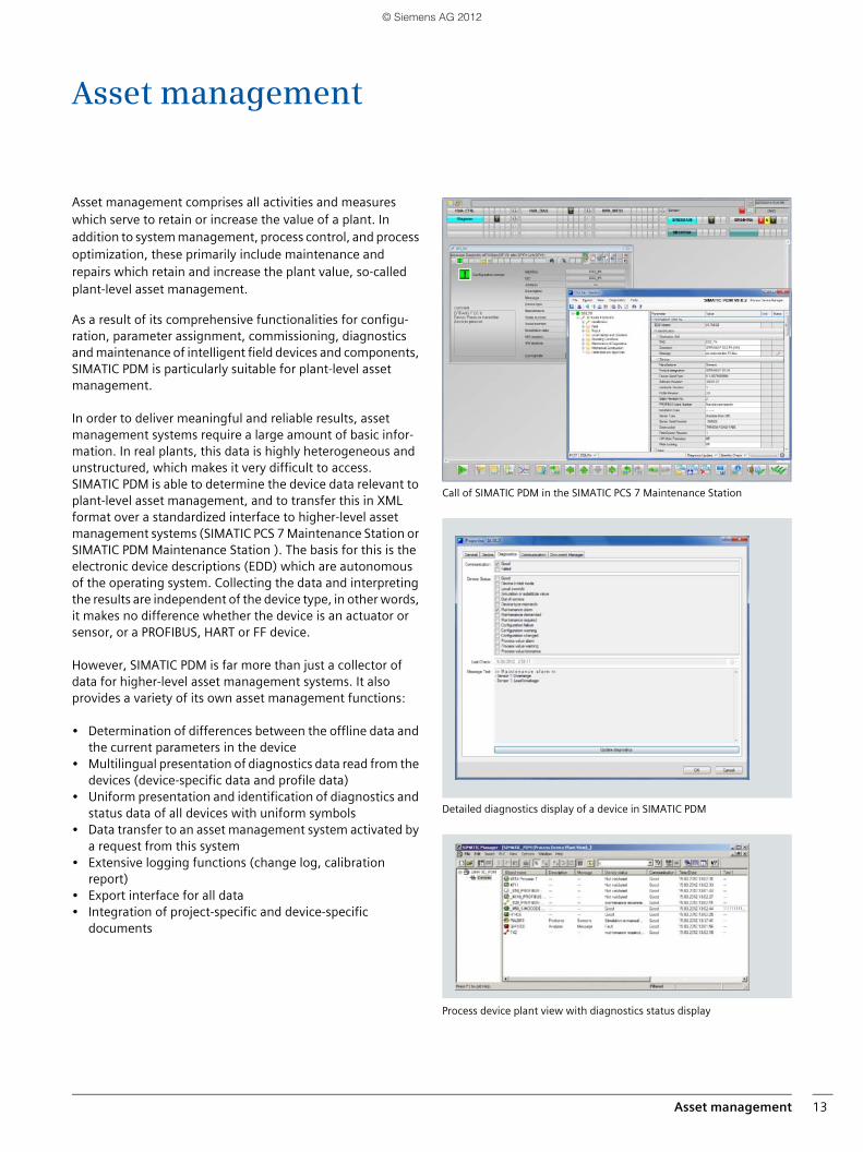
In order to deliver meaningful and reliable results, asset management systems require a large amount of basic infor-mation. In real plants, this data is highly heterogeneous and unstructured, which makes it very difficult to access. SIMATIC PDM is able to determine the device data relevant to plant-level asset management, and to transfer this in XML format over a standardized interface to higher-level asset management systems (SIMATIC PCS 7 Maintenance Station or SIMATIC PDM Maintenance Station ). The basis for this is the electronic device descriptions (EDD) which are autonomous of the operating system. Collecting the data and interpreting the results are independent of the device type, in other words, it makes no difference whether the device is an actuator or sensor, or a PROFIBUS, HART or FF device.
However, SIMATIC PDM is far more than just a collector of data for higher-level asset management systems. It also provides a variety of its own asset management functions:
• Determination of differences between the offline data and the current parameters in the device
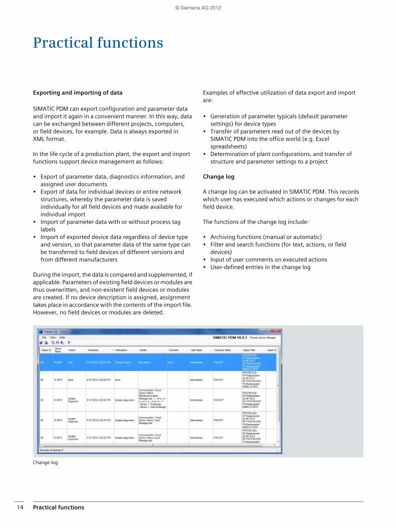
• Multilingual presentation of diagnostics data read from the devices (device-specific data and profile data)
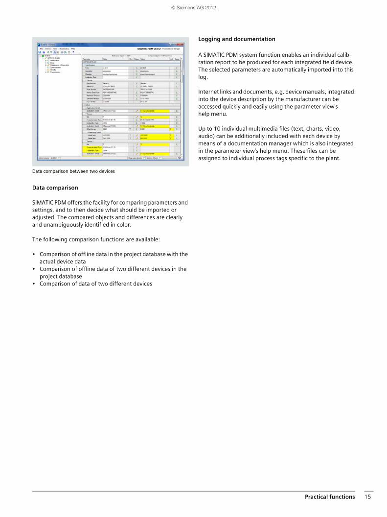
• Uniform presentation and identification of diagnostics and status data of all devices with uniform symbols
• Data transfer to an asset management system activated by a request from this system
• Extensive logging functions (change log, calibration report)
• Export interface for all data• Integration of project-specific and device-specific
documents
Call of SIMATIC PDM in the SIMATIC PCS 7 Maintenance Station
Detailed diagnostics display of a device in SIMATIC PDM
Process device plant view with diagnostics status display
© Siemens AG 2012
Practical functions14
Practical functions
Exporting and importing of data
SIMATIC PDM can export configuration and parameter data and import it again in a convenient manner. In this way, data can be exchanged between different projects, computers, or field devices, for example. Data is always exported in XML format.
In the life cycle of a production plant, the export and import functions support device management as follows:
• Export of parameter data, diagnostics information, and assigned user documents
• Export of data for individual devices or entire network structures, whereby the parameter data is saved individually for all field devices and made available for individual import
• Import of parameter data with or without process tag labels
• Import of exported device data regardless of device type and version, so that parameter data of the same type can be transferred to field devices of different versions and from different manufacturers
During the import, the data is compared and supplemented, if applicable. Parameters of existing field devices or modules are thus overwritten, and non-existent field devices or modules are created. If no device description is assigned, assignment takes place in accordance with the contents of the import file. However, no field devices or modules are deleted.
Examples of effective utilization of data export and import are:
• Generation of parameter typicals (default parameter settings) for device types
• Transfer of parameters read out of the devices by SIMATIC PDM into the office world (e.g. Excel spreadsheets)
• Determination of plant configurations, and transfer of structure and parameter settings to a project
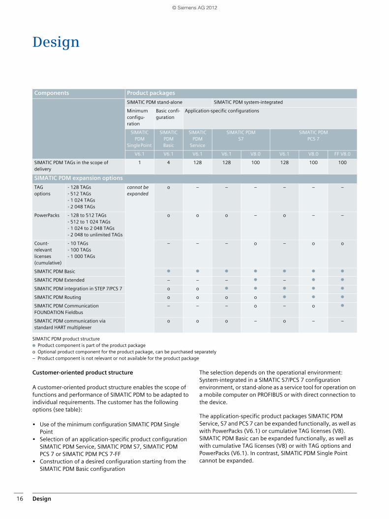
Change log
A change log can be activated in SIMATIC PDM. This records which user has executed which actions or changes for each field device.
The functions of the change log include:
• Archiving functions (manual or automatic)• Filter and search functions (for text, actions, or field
devices)• Input of user comments on executed actions• User-defined entries in the change log
Change log
© Siemens AG 2012
Practical functions 15
Data comparison between two devices
Data comparison
SIMATIC PDM offers the facility for comparing parameters and settings, and to then decide what should be imported or adjusted. The compared objects and differences are clearly and unambiguously identified in color.
The following comparison functions are available:
• Comparison of offline data in the project database with the actual device data
• Comparison of offline data of two different devices in the project database
• Comparison of data of two different devices
Logging and documentation
A SIMATIC PDM system function enables an individual calib-ration report to be produced for each integrated field device. The selected parameters are automatically imported into this log.
Internet links and documents, e.g. device manuals, integrated into the device description by the manufacturer can be accessed quickly and easily using the parameter view's help menu.
Up to 10 individual multimedia files (text, charts, video, audio) can be additionally included with each device by means of a documentation manager which is also integrated in the parameter view's help menu. These files can be assigned to individual process tags specific to the plant.
© Siemens AG 2012
Design16
Design
SIMATIC PDM product structuren Product component is part of the product package o Optional product component for the product package, can be purchased separately– Product component is not relevant or not available for the product package
Customer-oriented product structure
A customer-oriented product structure enables the scope of functions and performance of SIMATIC PDM to be adapted to individual requirements. The customer has the following options (see table):
• Use of the minimum configuration SIMATIC PDM Single Point
• Selection of an application-specific product configuration SIMATIC PDM Service, SIMATIC PDM S7, SIMATIC PDM PCS 7 or SIMATIC PDM PCS 7-FF
• Construction of a desired configuration starting from the SIMATIC PDM Basic configuration
The selection depends on the operational environment: System-integrated in a SIMATIC S7/PCS 7 configuration environment, or stand-alone as a service tool for operation on a mobile computer on PROFIBUS or with direct connection to the device.
The application-specific product packages SIMATIC PDM Service, S7 and PCS 7 can be expanded functionally, as well as with PowerPacks (V6.1) or cumulative TAG licenses (V8). SIMATIC PDM Basic can be expanded functionally, as well as with cumulative TAG licenses (V8) or with TAG options and PowerPacks (V6.1). In contrast, SIMATIC PDM Single Point cannot be expanded.
Components Product packages
SIMATIC PDM stand-alone SIMATIC PDM system-integrated
Minimum configu-ration
Basic confi-guration
Application-specific configurations
SIMATIC PDM
Single Point
SIMATIC PDMBasic
SIMATIC PDM
Service
SIMATIC PDMS7
SIMATIC PDM PCS 7
V6.1 V6.1 V6.1 V6.1 V8.0 V6.1 V8.0 FF V8.0
SIMATIC PDM TAGs in the scope of delivery
1 4 128 128 100 128 100 100
SIMATIC PDM expansion options
TAG options
- 128 TAGs - 512 TAGs- 1 024 TAGs- 2 048 TAGs
cannot be expanded
o – – – – – –
PowerPacks - 128 to 512 TAGs- 512 to 1 024 TAGs- 1 024 to 2 048 TAGs- 2 048 to unlimited TAGs
o o o – o – –
Count-relevant licenses (cumulative)
- 10 TAGs- 100 TAGs- 1 000 TAGs
– – – o – o o
SIMATIC PDM Basic n n n n n n n
SIMATIC PDM Extended – – – n – n n
SIMATIC PDM integration in STEP 7/PCS 7 o o n n n n n
SIMATIC PDM Routing o o o o n n n
SIMATIC PDM Communication FOUNDATION Fieldbus
– – – o – o n
SIMATIC PDM communication via standard HART multiplexer
o o o – o – –
© Siemens AG 2012
Design 17
A TAG corresponds to a SIMATIC PDM object, which represents individual field devices or components within a project, e.g. measuring instruments, positioners, switching devices or remote I/Os. Also regarded as a TAG is every diagnostics-enabled device detected by diagnostics with the Lifelist whose detailed diagnostics are implemented via the device description (EDD).
SIMATIC PDM Single Point (V6.1)This low-cost minimum configuration with handheld functio-nality is tailored to processing exactly one field device via a point-to-point connection. It is not expandable. All device functions are supported as defined in the device description.
SIMATIC PDM Basic (V6.1/V8)This is the basis for generation of individual SIMATIC PDM configurations from individual components. It contains all the functions required for operation and parameter assignment of the devices, and the communication paths enabled for PROFIBUS, DP/PA, PROFINET, Modbus and HART communi-cation.
SIMATIC PDM Basic without TAG expansion can manage projects with as many as 4 TAGs and, provided the system requirements are met, can be used for stand-alone operation on any computers (PCs/notebooks) with local connection to bus segments or direct connection to the device.
SIMATIC PDM Service (V6.1/V8)This is a pre-configured product package specially designed for mobile use in servicing projects with up to 100/128 TAGs. It offers service technicians all the functions of SIMATIC PDM Basic and also permits use of the change log, calibration report, and detailed diagnostics in the Lifelist.
SIMATIC S7 (V6.1/V8)SIMATIC PDM S7 is an application-specific product package for projects with up to 100/128 TAGs and is configured for the use of SIMATIC PDM in a SIMATIC S7 configuration environment. SIMATIC PDM S7 combines the functional scope of SIMATIC PDM Basic (supplemented by change log, calib-ration report and detailed diagnostics in the Lifelist) with the functionality for integrating PDM in HW Config.
SIMATIC PDM PCS 7 (V6.1/V8)SIMATIC PDM PCS 7 is an application-specific product package for integration into the engineering system (engineering toolset) and the Maintenance Station of SIMATIC PCS 7, and is designed for projects with up to 100/128 TAGs. SIMATIC PDM PCS 7 expands the functional scope of SIMATIC PDM Basic (supplemented by change log, calibration report and detailed diagnostics in the Lifelist) by the functions for integrating PDM in HW Config and routing from the central engineering system to field devices.
SIMATIC PDM PCS 7-FF (V8)SIMATIC PDM PCS 7-FF combines the SIMATIC PDM PCS 7 product package, equipped for projects with up to 100 TAGs, with the optional product component SIMATIC PDM Commu-nication FOUNDATION Fieldbus. In addition to the previously described SIMATIC PDM PCS 7 functionality, the Process Device Manager thus also has the capability of communi-cating with field devices on the FOUNDATION Fieldbus via the FF Link in a SIMATIC PCS 7 configuration environment.
SIMATIC PDM option "Integration in STEP 7/PCS 7" (V6.1/V8)This option is used for integrating SIMATIC PDM in a SIMATIC S7 or SIMATIC PCS 7 configuration environment. SIMATIC PDM can then be started directly from the hardware configurator (HW Config) in STEP 7/SIMATIC PCS 7.
SIMATIC PDM option Routing (V6.1/V8)This option is required in addition to the option "Integration in STEP7/PCS 7" if SIMATIC PDM is to be used in a central engineering system for SIMATIC S7/PCS 7, with Ethernet bus connection to the automation systems for plant-wide confi-guration, parameter assignment, commissioning and diagnostics of field devices. From the central engineering system, it is thus possible to reach every EDD-configurable device in the field plant-wide through the various bus systems and remote I/Os.
SIMATIC PDM option Extended (V8)This option for SIMATIC PDM Basic enables the use of expanded service functions such as change log, calibration report, or detailed diagnostics in the Lifelist.
SIMATIC PDM option Communication FOUNDATION Fieldbus (V8)With this option, SIMATIC PDM can communicate via the FF Link with field devices on the FOUNDATION Fieldbus H1.
SIMATIC PDM option "Communication via standard HART multiplexer" (V6.1)This option enables SIMATIC PDM to use the HART OPC server for communication with HART field devices via HART multi-plexers and WirelessHART adapters.
TAG options (V6.1)TAG options can be used to expand SIMATIC PDM Basic from 4 TAGs up to 128, 512, 1 024 or 2 048 TAGs.
PowerPacks (V6.1)With PowerPacks, TAG expansions with SIMATIC PDM Basic, Service, S7 and PCS 7 are possible. The number of TAGs can then be increased in stages from 128 to 512, 1 024 and 2 048 up to unlimited TAGs.
SIMATIC PDM TAGs (V8)Depending on the project size, SIMATIC PDM Basic, Service, S7, PCS 7 and PCS 7-FF can be expanded with cumulative licenses for 10, 100 and 1 000 TAGs (count-relevant licenses).
© Siemens AG 2012
Benefits18
Benefits
General product features
■ Powerful software with uniform user interface and comprehensive functions for engineering, parameter assignment, commissioning, diagnostics and maintenance of field devices and components
■ Intuitive and secure operation of all integrated devices based on a common user interface and operator guidance in 7 languages (English, German, French, Spanish, Italian, Chinese and Japanese)
■ Simple, functional and reliable device management
■ Uniform, easily recognizable diagnostics symbols for all devices
■ Archiving of all parameter, maintenance and diagnostics information in a consistent database
■ Can be used in stand-alone mode or integrated in the central SIMATIC PCS 7/S7 engineering system
■ Fundamental component of the SIMATIC PCS 7 Maintenance Station and the SIMATIC PDM Maintenance Station
Device integration and communication
■ Global leader in device integration: – More than 2 500 different devices from over
200 manufacturers worldwide– Almost all PROFIBUS PA devices are integrated– Almost all HART devices are integrated– Simple integration of new field devices and
components by importing their device description (EDD), which is independent of the operating system
– Existing device descriptions can be updated quickly and easily
■ Wide variety of options for communication with the devices, e.g. using PROFIBUS DP/PA, PROFINET, Modbus or HART communication (modem, RS 232, WirelessHART, PROFIBUS, or PROFINET): – With local connection of SIMATIC PDM on a
bus segment or directly on the device– From a central engineering system with
SIMATIC PDM using "Routing"
© Siemens AG 2012
19
SIMATIC PDM device list
You can find a device list (representative cross-section of the field devices and components that can be assigned parameters with SIMATIC PDM) in our Service & Support Portal on the Internet in the SIMATIC PDM product announcement about the current device description library:www.siemens.com/automation/support
Detail functions
■ Access to all parameters as well as all diagnostics and maintenance information of a device
■ Comparison of parameter sets (e.g. reference and actual parameters, or online/offline data of two devices)
■ Display of process values with status
■ Simulation of process values for loop tests
■ Determination, processing and presentation of device data for asset management
■ Global and device-specific change log (audit trail)
■ Device-specific calibration report
■ Homogeneous and consistent help texts for the devices, generated from the device descriptions
■ Integration of up to 10 multimedia files per document manager
■ Comparison function
User advantages and rationalization potential
■ High degree of standardization through compliant device descriptions (EDD) based on an internationally standardized language (EDDL)
■ Rationalization of configuration and parameter assignment using convenient export and import functions
■ High plant availability through device parameters which can be modified online
■ Low training requirements through intuitive operator guidance as well as functions which are easy to learn, operate and understand
© Siemens AG 2012
Get more information
Wide range of information on all aspects of the SIMATIC PDM Process Device Manager:www.siemens.com/simatic-pdm
Information on device integration:support.automation.siemens.com/WW/view/en/50898953
Current information on all aspects of the process control system SIMATIC PCS 7:www.siemens.com/simatic-pcs7
Totally Integrated Automation:www.siemens.com/totally-integrated-automation
SIMATIC Guide manuals:www.siemens.com/simatic-docu
Information material available for downloading:www.siemens.com/simatic/printmaterial
Service & Support:www.siemens.com/automation/support
SIMATIC contact partners:www.siemens.com/automation/partner
Industry Mall for electronic ordering:www.siemens.com/automation/mall
The information provided in this brochure contains descriptions or
characteristics of performance which in case of actual use do not
always apply as described or which may change as a result of further
development of the products. An obligation to provide the respective
characteristics shall only exist if expressly agreed in the terms of
contract. Availability and technical specifications are subject to change
without notice.
All product designations may be trademarks or product names of
Siemens AG or supplier companies, whose use by third parties for their
own purposes could violate the rights of the owners.
Siemens AGIndustry SectorIndustrial Automation SystemsPostfach 48 4890026 NUREMBERGGERMANY
Subject to changePDF (E86060-A4678-A161-A5-7600)MP.R4.AS.SMP7.02.3.01BR 1112 20 EnProduced in Germany © Siemens AG 2012
www.siemens.com/automation
Umschlag_Br_PDM_2012_en.indd 2 09.11.2012 15:10:32
© Siemens AG 2012