proceedings of spie - · lorenzo valdevit, "3d manufacturing of micro and nano-architected...
TRANSCRIPT

PROCEEDINGS OF SPIE
SPIEDigitalLibrary.org/conference-proceedings-of-spie
3D manufacturing of micro and nano-architected materials
Lorenzo Valdevit
Lorenzo Valdevit, "3D manufacturing of micro and nano-architectedmaterials," Proc. SPIE 9738, Laser 3D Manufacturing III, 97380K (6 April2016); doi: 10.1117/12.2217910
Event: SPIE LASE, 2016, San Francisco, California, United States
Downloaded From: https://www.spiedigitallibrary.org/conference-proceedings-of-spie on 2/26/2018 Terms of Use: https://www.spiedigitallibrary.org/terms-of-use

3D manufacturing of micro and nano-architected materials Lorenzo Valdevit*
Mechanical and Aerospace Engineering Dept., University of California at Irvine, Irvine, CA 92697
ABSTRACT
Reducing mass without sacrificing mechanical integrity and performance is a critical goal in a vast range of applications. Introducing a controlled amount of porosity in a strong and dense material (hence fabricating a cellular solid) is an obvious avenue to weight reduction. The mechanical effectiveness of this strategy, though, depends strongly on the architecture of the resulting cellular material (i.e., the topology of the introduced porosity). Recent progress in additive manufacturing enables fabrication of macro-scale cellular materials (both single-phase and hybrid) with unprecedented dimensional control on the unit-cell and sub-unit-cell features, potentially producing architectures with structural hierarchy from the nano to the macro-scale. As mechanical properties of materials often exhibit beneficial size effects at the nano-scale (e.g., strengthening of metals and toughening of ceramics), these novel manufacturing approaches provide a unique opportunity to translate these beneficial effects to the macro-scale, further improving the mechanical performance of architected materials. The enormous design space for architected materials, and the strong relationship between the topological features of the architecture and the effective physical and mechanical properties of the material at the macro-scale, present both a huge opportunity and an urgent need for the development of suitable optimal design strategies. Here we present a number of strategies for the advanced manufacturing, characterization and optimal design of a variety of lightweight architected materials with unique combinations of mechanical properties (stiffness, strength, damping coefficient…). The urgent need to form strong synergies among the fields of additive manufacturing, topology optimization and architecture-properties relations is emphasized throughout.
Keywords: Architected materials, cellular materials, 3D additive manufacturing, nanotechnology, microlattices, nanolattices, topology optimization.
1. INTRODUCTION Reducing mass without sacrificing mechanical integrity and performance is a critical goal in a vast range of fields. Unfortunately, monolithic materials with the largest strength and density are also typically the heaviest; technical ceramics are an exception, but their high strength only occurs under compressive loads, as the strength of these materials is plagued by their high flaw sensitivity in tension. Introducing a controlled amount of porosity in a strong and dense material (hence fabricating a cellular material) is an obvious avenue to weight reduction. The mechanical effectiveness of this strategy, though, depends strongly on the architecture of the resulting cellular material (i.e., the topology of the introduced porosity). Three-dimensional lattices (consisting of bars connecting at nodes in 3D space) are a classical example of cellular materials; these lattices have been extensively investigated over the past two decades, thanks to their enormous mechanical efficiency and their amenability to simple optimization studies. Traditional manufacturing processes for lattices (e.g., see 1,2) limit the smallest feature size to ~100 microns. At these scales, the mechanical properties of the base material are the same as in the bulk. Over the past five years, the dramatic advances in additive manufacturing processes have reduced this minimum size to the sub-micron, and even the nanometer scale, thus opening the doors to the exploitation of nanoscale size effects. This article summarizes the key structural benefits of solid and hollow lattices, discusses beneficial size effects when the smallest feature in the architecture is reduced to the micro and nanoscale, presents the latest advances in manufacturing processes and demonstrates some unique mechanical features of micro and nanolattices. A number of techniques for the optimal design of lattice materials (and architected materials in general) are briefly reviewed at the end. Some of the concepts presented in this article, with particular emphasis on applications of two-photon polymerization Direct Laser Writing techniques, have appeared in a book chapter by the same author3.
*[email protected]; phone 1 949 824-4173; fax 1 949 824-8585; http://valdevit.eng.uci.edu
Invited Paper
Laser 3D Manufacturing III, edited by Bo Gu, Henry Helvajian, Alberto Piqué, Proc. of SPIEVol. 9738, 97380K · © 2016 SPIE · CCC code: 0277-786X/16/$18 · doi: 10.1117/12.2217910
Proc. of SPIE Vol. 9738 97380K-1
Downloaded From: https://www.spiedigitallibrary.org/conference-proceedings-of-spie on 2/26/2018 Terms of Use: https://www.spiedigitallibrary.org/terms-of-use
2. MECHANICAL BENEFITS OF ARCHITECTED MATERIALS 2.1 Topological design of the unit cell architecture
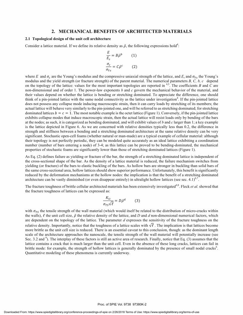
Consider a lattice material. If we define its relative density as , the following expressions hold4:
where E and are the Young’s modulus and the compressive uniaxial strength of the lattice, and Es and the Young’s modulus and the yield strength (or fracture strength) of the parent material. The numerical parameters B, C, b, c depend on the topology of the lattice: values for the most important topologies are reported in 4,5. The coefficients B and C are non-dimensional and of order 1. The power-law exponents b and c govern the mechanical behavior of the material, and their values depend on whether the lattice is bending or stretching dominated. To appreciate the difference, one should think of a pin-jointed lattice with the same nodal connectivity as the lattice under investigation4. If the pin-jointed lattice does not possess any collapse mode inducing macroscopic strain, then it can carry loads by stretching of its members; the actual lattice will behave very similarly to the pin-jointed one, and will be referred to as stretching dominated; for stretching dominated lattices . The most notable example is the octet lattice (Figure 1). Conversely, if the pin-jointed lattice exhibits collapse modes that induce macroscopic strain, then the actual lattice will resist loads only by bending of the bars at the nodes; as such, it is categorized as bending dominated, and will exhibit values of b and c larger than 1; a key example is the lattice depicted in Figure 6. As we are concerned with relative densities typically less than 0.2, the difference in strength and stiffness between a bending and a stretching dominated architecture at the same relative density can be very significant. Stochastic open-cell foams (whether natural or man-made) are a typical example of cellular material: although their topology is not perfectly periodic, they can be modeled quite accurately as an ideal lattice exhibiting a coordination number (number of bars entering a node) of 3-4; as this lattice can be proved to be bending-dominated, the mechanical properties of stochastic foams are significantly lower than those of stretching dominated lattices (Figure 1).
As Eq. (2) defines failure as yielding or fracture of the bar, the strength of a stretching dominated lattice is independent of the cross-sectional shape of the bar. As the density of a lattice material is reduced, the failure mechanism switches from yielding (or fracture) of the bars to elastic buckling of the bars. As hollow bars are stronger in buckling than solid bars of the same cross-sectional area, hollow lattices should show superior performance. Unfortunately, this benefit is significantly reduced by the deformation mechanisms at the hollow nodes: the implication is that the benefit of a stretching dominated architecture can be vastly diminished (or even disappear entirely) in ultralight hollow lattices (see sec. 4.1)6,7.
The fracture toughness of brittle cellular architected materials has been extensively investigated4,8. Fleck et al. showed that the fracture toughness of lattices can be expressed as:
with the tensile strength of the wall material (which would itself be related to the distribution of micro-cracks within the walls), the unit cell size, the relative density of the lattice, and D and d non-dimensional numerical factors, which are dependent on the topology of the lattice. The parameter d expresses the sensitivity of the fracture toughness on the relative density. Importantly, notice that the toughness of a lattice scales with . The implication is that lattices become more brittle as the unit cell size is reduced. There is an essential caveat to this conclusion, though: as the dominant length scale of the architecture approaches the nanoscale, the tensile strength of the wall material will potentially increase (see Sec. 3.2 and 9). The interplay of these factors is still an active area of research. Finally, notice that Eq. (3) assumes that the lattice contains a crack that is much larger than the unit cell. Even in the absence of these long cracks, lattices can fail in brittle mode: for example, the strength of hollow lattices is generally dominated by the presence of small nodal cracks6. Quantitative modeling of these phenomena is currently underway.
Proc. of SPIE Vol. 9738 97380K-2
Downloaded From: https://www.spiedigitallibrary.org/conference-proceedings-of-spie on 2/26/2018 Terms of Use: https://www.spiedigitallibrary.org/terms-of-use

wu Int¢rv vgepturuwA
ireiatlE P w ayw., 3aa
sp"wV+aEO H
o, o1
AD
_o1 4 £C0= cc9 AD +,g
O 3 ,g
.01
dZO-EEy
oipopad
AD zicd SZ'0=
s
oi;Seyoo;S
IMPROVED
STRENGTH
AT THE
MACROSCALE
BULK1 -100 cm
MESO SCALE
-100 pmMICRO /NANOSCALE-100nm - 10pm
UNIQUE DEFORMATION MECHANISMS
IMPROVED STRENGTH AT THE FILM LEVEL k
SIZE EFFECTS
IN PLASTICITYAND FRACTURE
Figure 1. The role of architecture of a cellular material on compressive stiffness and strength. Stochastic foams are defective and bending dominated, resulting in inferior mechanical behavior when compared with topologically optimized architected periodic materials, such as the octet lattice whose unit cell is depicted in the middle. For relative density lower than 10%, the difference in stiffness and strength is very significant (see plot on right). Notice that the octet lattice can almost achieve theoretical bounds on both properties. (Plot reproduced from 5).
2.2 Nanoscale benefits on strength of materials
Traditional manufacturing processes for architected materials (e.g., see 1,2) limit the smallest feature size to ~100 microns. At these scales, the mechanical properties of the base material are the same as in the bulk. Over the past five years, the dramatic advances in additive manufacturing processes discussed in this article have reduced this minimum size to the sub-micron, and even the nanometer scale, thus opening the doors to the exploitation of nanoscale size effects (Figure 2). The most important size effects are discussed in this section.
Figure 2. Micro/nanoarchitected materials possess a structural hierarchy (ratio between the largest and smallest dimension in the architecture) of at least 5 orders of magnitude, allowing to capitalize on beneficial nanoscale size effects on yielding and fracture strength in a macroscale material. The very large structural bandwidth may also result in unique deformation mechanisms not easily observed in classic cellular materials.
a. Scale dependent yield strength in metals
Plastic flow in metals generally occurs by motion of dislocations along preferential slip systems. As dislocation motion is hindered by grain boundaries, the yield strength of a polycrystalline metal increases as the grain size is reduced. This hardening law was formalized by Hall and Petch as10,11:
where expresses the resistance to dislocation motion through the lattice, k is a materials parameter and d is the average grain size. Eq. (4) predicts enormous strengthening as the grain size is reduced to the atomic scale (and the microstructure becomes amorphous); in practice, once the grain size goes below ~10 nm, plasticity becomes controlled by other mechanisms (primarily grain boundary sliding12 and shear banding13). For most metals, these mechanisms induce softening
Proc. of SPIE Vol. 9738 97380K-3
Downloaded From: https://www.spiedigitallibrary.org/conference-proceedings-of-spie on 2/26/2018 Terms of Use: https://www.spiedigitallibrary.org/terms-of-use
100
10
1
0.1
105 10` 10'Material thickness t [m]
Nanoscale Microscafe Macroscale
E/30
mum0( a t
rtes wcak
ALD thin film
Printed ma0beam5
Bulk
as the grain size is further reduced, with the implication that the optimal yield strength is achieved at grains size ~10-20 nm.
Manufacturing macro-scale metallic components with grain size at the nanoscale is currently extremely difficult, as the large surface energy associated with extensive grain boundaries is thermodynamics expensive. Interestingly, though, a number of metallic alloys can be deposited with nanoscale grain size in thin film form (with film thicknesses typically smaller than ~10-100μm, depending on the alloy)14-16. Hence, if a metallic thin film is deposited conformally on an architected polymeric template, and the template is subsequently etched away, a mascroscopic metallic architected material can be developed with nanoscale grain size, and hence an exceptionally high yield strength of the constituent alloy. With proper design of the template architecture, this exceptional thin film strength can be transferred to the macro-scale architected material. This approach was successfully employed in a number of recent studies17-19.
b. Scale dependent fracture strength in ceramics
Unlike ductile metals, ceramics and other brittle materials have a crystal structure that does not allow significant plastic deformation at ambient temperature. Furthermore, classic processing approaches for ceramic materials inevitably result in a distribution of defects (cracks) in the material. The lack of plastic flaw at the crack tip results in low toughness, and causes failure at applied stresses much lower than the yield strength of the material. According to Griffith’s law20, the fracture strength of a material, can be expressed by the relation:
where denotes the size of the largest crack in the material (assuming that crack are uniformly distributed in all directions), Y is a numerical constant and Kc is the fracture toughness (a material property that expresses the resistance to crack growth).
At the macroscale, the average crack size is relatively independent on the component size (assuming that the same manufacturing process is used); under these conditions, the strength depends on the component size (e.g., the film thickness) according to the weakest link theory: , with m the Weibull modulus of the material21. As the film thickness is reduced below the microscale, the average crack size approaches the film thickness, resulting in a scaling
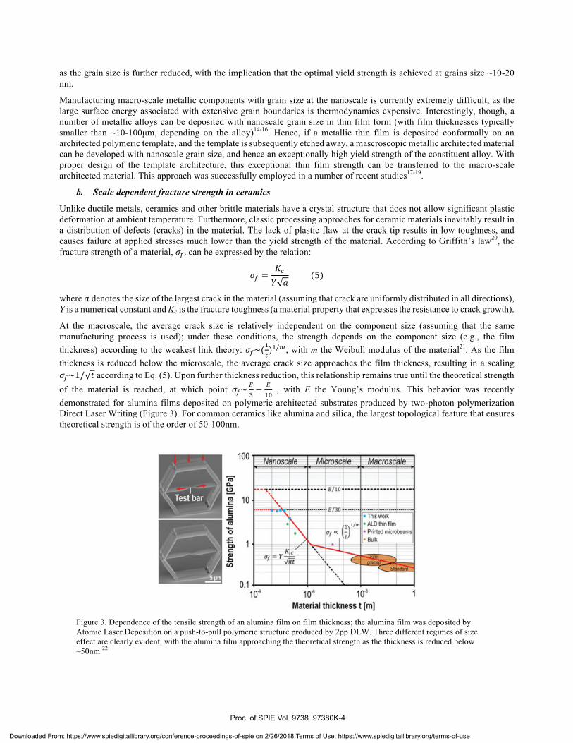
according to Eq. (5). Upon further thickness reduction, this relationship remains true until the theoretical strength of the material is reached, at which point , with E the Young’s modulus. This behavior was recently demonstrated for alumina films deposited on polymeric architected substrates produced by two-photon polymerization Direct Laser Writing (Figure 3). For common ceramics like alumina and silica, the largest topological feature that ensures theoretical strength is of the order of 50-100nm.
Figure 3. Dependence of the tensile strength of an alumina film on film thickness; the alumina film was deposited by Atomic Laser Deposition on a push-to-pull polymeric structure produced by 2pp DLW. Three different regimes of size effect are clearly evident, with the alumina film approaching the theoretical strength as the thickness is reduced below ~50nm.22
Proc. of SPIE Vol. 9738 97380K-4
Downloaded From: https://www.spiedigitallibrary.org/conference-proceedings-of-spie on 2/26/2018 Terms of Use: https://www.spiedigitallibrary.org/terms-of-use
Fabricationof solid polymericmicro /nanolattice
Thin filmdeposition of
structural material
Pyrolysis ofsolid polymeric
micro / nanolattice
Chemical Etchof Polymer
Solid hybridmicro /nanolattice
Solid ceramicmicro /nanolattice
Hollowmetallic or ceramicmicro /nanolattice
3. MANUFACTURING PROCESSES FOR STRUCTURAL MICRO AND NANOLATTICES
All the traditional approaches for manufacturing of structural lattices (e.g., 1,23) result in unit cell sizes in the centimeter range and minimum lattice bar diameters of the order of hundreds of microns. Direct metal laser sintering (or electron beam melting) approaches reduce the minimum unit cell size to a few millimeters, but the limitation on the bar diameter remains; furthermore, the mechanical properties of 3D printed metallic lattices are still poorly characterized, and the resulting architected materials are highly susceptible to fatigue failure, due to the rough surface finish. Addressing these limitations is a current area of research.
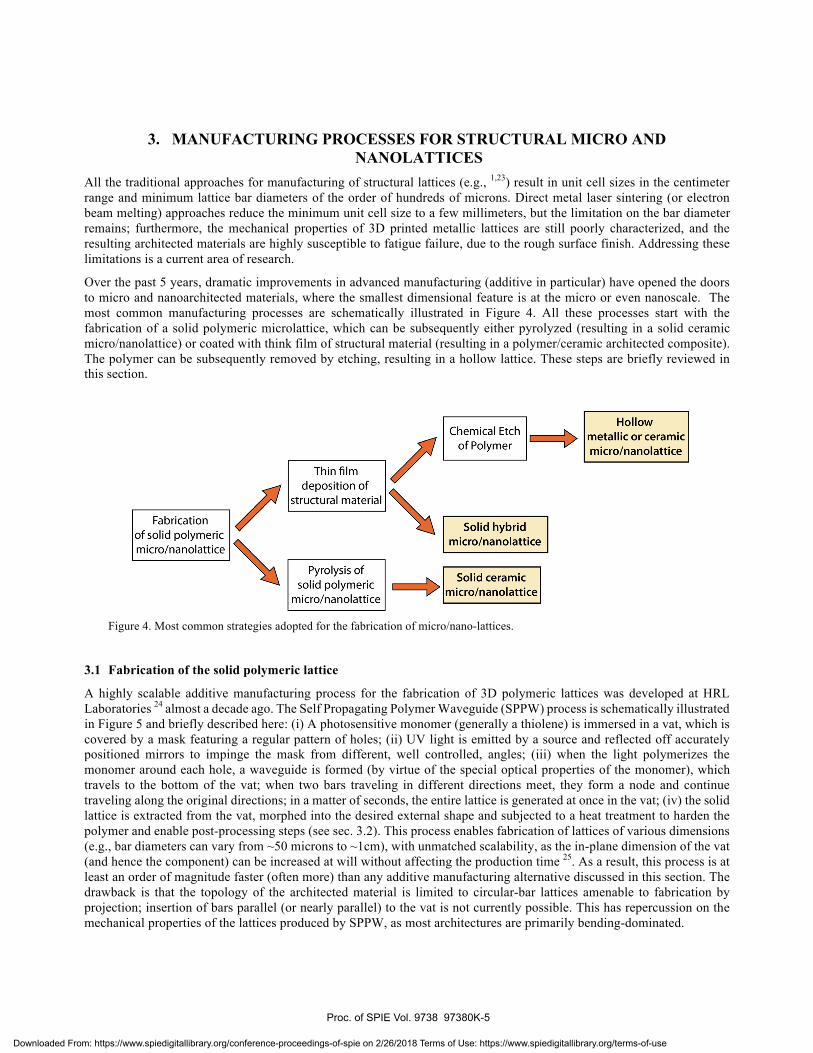
Over the past 5 years, dramatic improvements in advanced manufacturing (additive in particular) have opened the doors to micro and nanoarchitected materials, where the smallest dimensional feature is at the micro or even nanoscale. The most common manufacturing processes are schematically illustrated in Figure 4. All these processes start with the fabrication of a solid polymeric microlattice, which can be subsequently either pyrolyzed (resulting in a solid ceramic micro/nanolattice) or coated with think film of structural material (resulting in a polymer/ceramic architected composite). The polymer can be subsequently removed by etching, resulting in a hollow lattice. These steps are briefly reviewed in this section.
Figure 4. Most common strategies adopted for the fabrication of micro/nano-lattices.
3.1 Fabrication of the solid polymeric lattice
A highly scalable additive manufacturing process for the fabrication of 3D polymeric lattices was developed at HRL Laboratories 24 almost a decade ago. The Self Propagating Polymer Waveguide (SPPW) process is schematically illustrated in Figure 5 and briefly described here: (i) A photosensitive monomer (generally a thiolene) is immersed in a vat, which is covered by a mask featuring a regular pattern of holes; (ii) UV light is emitted by a source and reflected off accurately positioned mirrors to impinge the mask from different, well controlled, angles; (iii) when the light polymerizes the monomer around each hole, a waveguide is formed (by virtue of the special optical properties of the monomer), which travels to the bottom of the vat; when two bars traveling in different directions meet, they form a node and continue traveling along the original directions; in a matter of seconds, the entire lattice is generated at once in the vat; (iv) the solid lattice is extracted from the vat, morphed into the desired external shape and subjected to a heat treatment to harden the polymer and enable post-processing steps (see sec. 3.2). This process enables fabrication of lattices of various dimensions (e.g., bar diameters can vary from ~50 microns to ~1cm), with unmatched scalability, as the in-plane dimension of the vat (and hence the component) can be increased at will without affecting the production time 25. As a result, this process is at least an order of magnitude faster (often more) than any additive manufacturing alternative discussed in this section. The drawback is that the topology of the architected material is limited to circular-bar lattices amenable to fabrication by projection; insertion of bars parallel (or nearly parallel) to the vat is not currently possible. This has repercussion on the mechanical properties of the lattices produced by SPPW, as most architectures are primarily bending-dominated.
Proc. of SPIE Vol. 9738 97380K-5
Downloaded From: https://www.spiedigitallibrary.org/conference-proceedings-of-spie on 2/26/2018 Terms of Use: https://www.spiedigitallibrary.org/terms-of-use

(a) Self Propagating Photopolymer Waveguide (SPPW) Process
Collimated
Mask 71 MINN7171
PolymerWaveg side
Monome
(c)Two- photon Polymerization Direc Laser Write Process
3 -D CAD Model
DLW Process INanoscribelPolymeric part
(b) Projection Micro Stereolithography Process
Digi al mask
3 -D CADmodel H,
rBeam
\\Elevato
delivery
\ ion lensc o I2
111UV curable resin
Polymer pail
Layer-by-layer processes based on laser scanning (or projection through a digital mask) enable fabrication of lattices (and architected materials in general) with nearly arbitrary architectures and external shapes, thus taking full advantage of topology optimization techniques for architecture design (see sec. 5). Stereolithography (SLA) is one of the best established additive manufacturing process. In its original configuration, a thin layer of liquid photosensitive monomer is deposited on the build platform, a laser beam is scanned on the monomer layer to selectively crosslink it, the printed layer is lowered and covered with a new layer of liquid monomer, and the process is repeated until the part (in this case a lattice) is fully printed26. More recent implementations replace the laser scanning with DLP projection, whereby a digital mask is used to simultaneously illuminate the entire layer at once. The minimum feature size is generally of the order of 100 microns. A projection lens can be used to reduce the feature size by an order of magnitude, in a technique called projection micro stereolithography (Figure 5)18. More dramatic improvements in resolution are only possible with two-photon polymerization processes3. A photosensitive monomer that only cross-links under the simultaneous action of two photons is used, in conjunction with a high performance laser that highly localizes the probability of the two-photon polymerization events. The result is a resolution of the order of a few hundred nanometers. Initially developed for the fabrication of photonic crystals (periodic materials with periodicity of the order of the wavelength of light)27, this approach has been successfully used over the past 3 years for the manufacturing of ultra high resolution microlattices, allowing investigation of a number of interesting size effects on plasticity and fracture of nanoscale architected thin films (see secs. 2 and 4); as such, it is a perfect process for fundamental research studies on structural architected materials. Currently, the most severe limitation of this process is the slow build time; although the write speed is increasing fast, at this time manufacturing of a lattice with external dimensions larger than a few centimeters is not a realistic process, even for high-value components.
Figure 5. Process schematic of three novel fabrication processes for solid polymeric micro/nanolattices. After fabrication, the solid polymeric lattice can be converted to a structural architected material by thin film coating (with or without polymer removal) or pyrolysis. (a) Self Propagating Photopolymer Waveguide (SPPW) process24; (b) Projection Micro Stereolithography18; (c) Two-Photon Polymerization Direct Laser Write process30,31.
3.2 Coating of the polymeric lattices with metallic or ceramic films
The polymeric lattice preforms fabricated with the processes described in sec. 3.1 can be subsequently coated with structural films using a variety of thin film deposition processes. With few exception, the process of choice should not require a conductive substrate, line-of-sight access to the substrate, or high temperature, and should produce a conformal coating with uniform thickness throughout the sample. To date, a number of processes have been demonstrated for deposition of a wide range of materials on SPPW-produced polymeric lattices: nickel and copper (electroless metal deposition), gold (electron beam evaporation), parylene (chemical vapor deposition), silicon dioxide and aluminum oxide (atomic layer deposition) 28. The same processes are applicable to SLA-produced polymeric lattices, including those produced by projection micro-stereolithography18. Metals can be deposited by electrodeposition after a seed layer of electroless Nickel is applied on the polymeric lattice29. Ultra-thin films deposited on 2pp-produced substrates include aluminum oxide30,31 and gold32, by atomic layer deposition and sputtering, respectively.
Proc. of SPIE Vol. 9738 97380K-6
Downloaded From: https://www.spiedigitallibrary.org/conference-proceedings-of-spie on 2/26/2018 Terms of Use: https://www.spiedigitallibrary.org/terms-of-use
High-temperature processes for deposition of ceramic films or refractory metals (e.g., chemical vapor deposition) are in principle possible but more challenging, as they require pyrolysis of the substrate, which can then be subsequently removed by oxidation (> 600°C in air).
3.3 Polymer etching and fabrication of hollow micro/nanolattices
To generate ultralight architected materials with exceptional specific stiffness and strength (or to produce high-temperature architected materials), the solid polymeric template must be removed after deposition of the structural film. For bar diameters larger than ~50 microns, a wet etching with NaOH has proven very effective and has been adopted in a number of studies17,28,33. Thermal decomposition is another possible route, successfully demonstrated in 18. For thinner bars (down to a few microns) produced by a 2pp process, Oxygen plasma etching has been demonstrated7,32.
3.4 Fabrication of solid ceramic micro/nanolattices by polymer pyrolysis
An alternative process to the coating of a (generally sacrificial) polymeric template as described above is the pyrolysis of the template to fabricate a fully ceramic solid lattice (or any other architected material). The most delicate step in this process is the synthesis of the preceramic monomer to ensure the pyrolyzed ceramics are fully dense and possess the desired stoichiometry. Additionally, the preceramic monomer must possess the optical properties needed for efficient photopolymerization. Very recently, photosensitive preceramic monomers were synthesized and lattices were fabricated via stereolithograpy and the SPPW process described in sec. 3.2. Fully dense amorphous silicon oxycarbide (SiOC) solid lattices were demonstrated, and were shown to possess compressive and shear strength much higher than silicon oxycarbide foams of comparable density.34
4. MECHANICAL PERFORMANCE OF MICRO/NANOLATTICES 4.1 Specific strength
Lattices can fail by a number of possible mechanisms, i.e., local (shell) or global (Euler) elastic buckling and plastic collapse (or fracture, for brittle lattices). The compressive strength can be estimated as the minimum of the critical stresses that activate any of these failure mechanisms. By relating the macroscopic stress at the lattice level to the stress state in each bar by equilibrium considerations (relationships that can be often casted in a simple analytical form), the strength of the lattice can be expressed by: , where for a hollow
lattice and for a solid lattice, with t the bar thickness, D its diameter , L is length and the angle of the diagonal bars relative to the horizontal direction. Although these expressions have been successfully
validated multiple times for solid lattices5,35, they tend to overpredict the strength of hollow microlattices6; these discrepancies are attributed to the major role played by the hollow nodes in controlling the deformation of the lattice and possible failure by nodal or film cracking. A unit-cell Finite Element analysis of a hollow microlattices can capture the former effect quite realistically through accurate meshing; although laborious to model accurately in a Finite Elements analysis, nodal fracture can be approximately captured by introducing free edge boundary conditions on all sides of the unit cell. Results for hollow nickel microlattices fabricated with the SPPW process described in the previous section are presented in Figure 6a, and compared with experimental data points. Notice the near perfect agreement. A house built algorithm coded in C++ was then produced to parametrically generate hollow unit cell meshes like the to one illustrated in Figure 6a for any possible value of the design parameters, and subsequently extract strength values from finite elements simulations 6,36. This allows efficient and accurate mapping of the entire compression VS density material properties space (Figure 6b). Notice that hollow lattices made of the same base material (Ni-P) and produced with the same process can span 3 orders of magnitude in density and 6 orders of magnitude in strength, an enormous design space! Although analytical models of nodal fracture strength are currently being successfully developed and are showing good agreements with the experimental results in Figure 6a, detailed Finite Elements simulations of geometrically accurate unit cells are essential to quantify the effect of nodal geometry on lattice strength; these models predict that stretching dominated lattices do not exhibit much higher strength of bending dominated lattices of the same density (Figure 7a), due to localized nodal
Proc. of SPIE Vol. 9738 97380K-7
Downloaded From: https://www.spiedigitallibrary.org/conference-proceedings-of-spie on 2/26/2018 Terms of Use: https://www.spiedigitallibrary.org/terms-of-use
100
Ñ
E 10-6o.E 1 o-7o
10-8
10-90 0001 0.001 0.01
Relative Density0.1
1010
109
108
107
106
105
104
103
107
101
A
a
Nkkelhollow
mkrolattkes Natural Materials
Technical Ceramic
Composites
3 Decades
Foams
Elasto
10 100 1000
Density (kg /m3)
10000
ó
10- Octet Lattice (stretching dominated)
HRL Lattice (bending dominated)
04 r
O5r
104 r
1ó5r
1o. F
10 °r
1040.0001
2 5. 5 6 2 2 5 5 6 10.001 0.01
Relative Density
é
-
4 56201
102
105
106
Free Vertical Edges Boundary Conditions
L/D-6 8 =60°
t
iI me
10X Improvement possible!!
twy/y- ttm/tr-atv./ty-t0
Relative Density
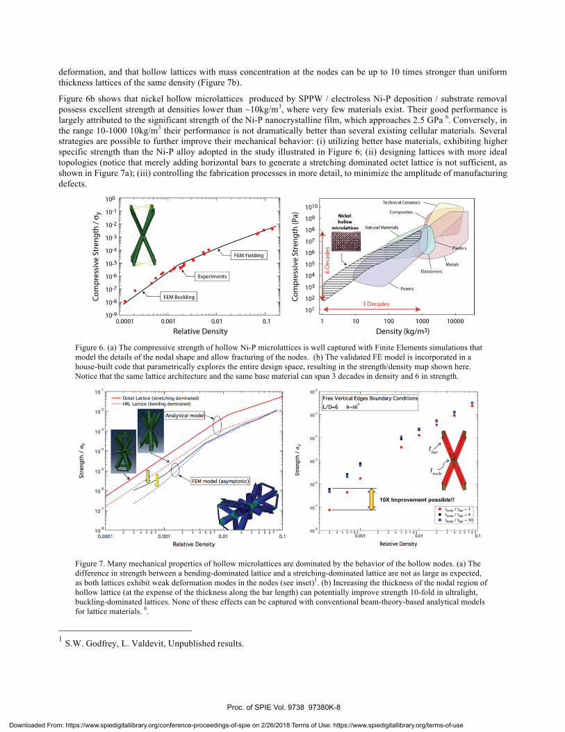
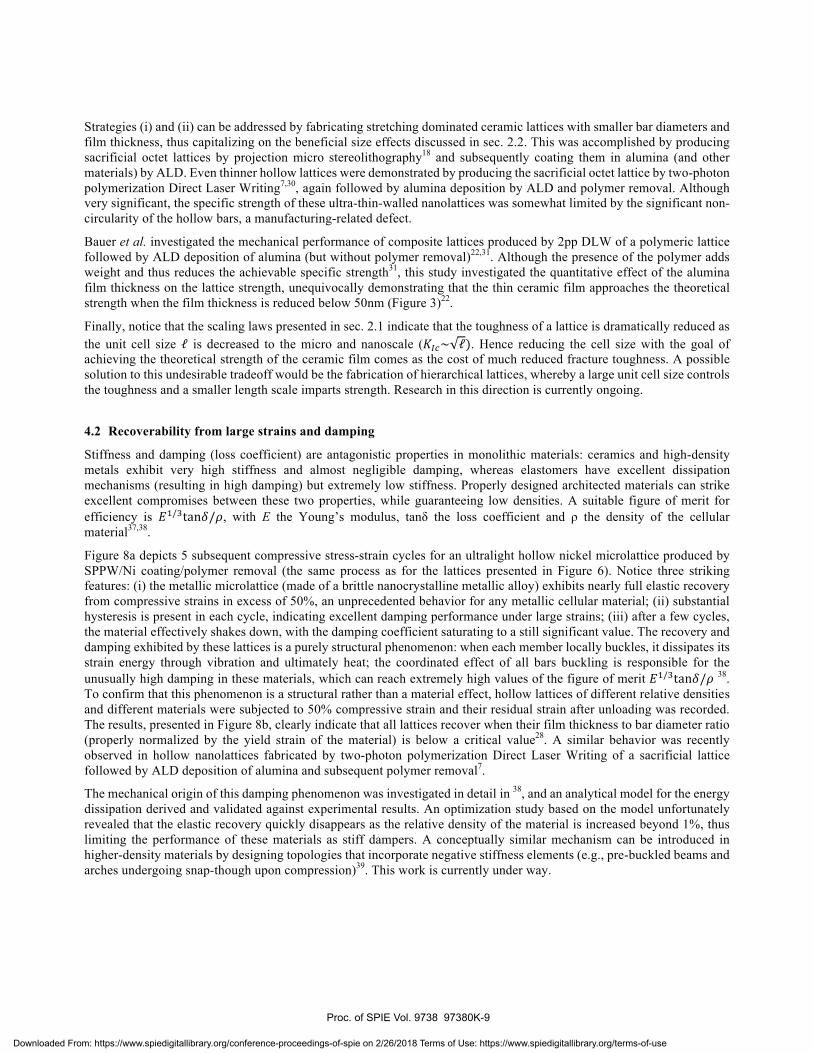
deformation, and that hollow lattices with mass concentration at the nodes can be up to 10 times stronger than uniform thickness lattices of the same density (Figure 7b).
Figure 6b shows that nickel hollow microlattices produced by SPPW / electroless Ni-P deposition / substrate removal possess excellent strength at densities lower than ~10kg/m3, where very few materials exist. Their good performance is largely attributed to the significant strength of the Ni-P nanocrystalline film, which approaches 2.5 GPa 6. Conversely, in the range 10-1000 10kg/m3 their performance is not dramatically better than several existing cellular materials. Several strategies are possible to further improve their mechanical behavior: (i) utilizing better base materials, exhibiting higher specific strength than the Ni-P alloy adopted in the study illustrated in Figure 6; (ii) designing lattices with more ideal topologies (notice that merely adding horizontal bars to generate a stretching dominated octet lattice is not sufficient, as shown in Figure 7a); (iii) controlling the fabrication processes in more detail, to minimize the amplitude of manufacturing defects.
Figure 6. (a) The compressive strength of hollow Ni-P microlattices is well captured with Finite Elements simulations that model the details of the nodal shape and allow fracturing of the nodes. (b) The validated FE model is incorporated in a house-built code that parametrically explores the entire design space, resulting in the strength/density map shown here. Notice that the same lattice architecture and the same base material can span 3 decades in density and 6 in strength.
Figure 7. Many mechanical properties of hollow microlattices are dominated by the behavior of the hollow nodes. (a) The difference in strength between a bending-dominated lattice and a stretching-dominated lattice are not as large as expected, as both lattices exhibit weak deformation modes in the nodes (see inset)1. (b) Increasing the thickness of the nodal region of hollow lattice (at the expense of the thickness along the bar length) can potentially improve strength 10-fold in ultralight, buckling-dominated lattices. None of these effects can be captured with conventional beam-theory-based analytical models for lattice materials. 6.
1 S.W. Godfrey, L. Valdevit, Unpublished results.
Proc. of SPIE Vol. 9738 97380K-8
Downloaded From: https://www.spiedigitallibrary.org/conference-proceedings-of-spie on 2/26/2018 Terms of Use: https://www.spiedigitallibrary.org/terms-of-use
Strategies (i) and (ii) can be addressed by fabricating stretching dominated ceramic lattices with smaller bar diameters and film thickness, thus capitalizing on the beneficial size effects discussed in sec. 2.2. This was accomplished by producing sacrificial octet lattices by projection micro stereolithography18 and subsequently coating them in alumina (and other materials) by ALD. Even thinner hollow lattices were demonstrated by producing the sacrificial octet lattice by two-photon polymerization Direct Laser Writing7,30, again followed by alumina deposition by ALD and polymer removal. Although very significant, the specific strength of these ultra-thin-walled nanolattices was somewhat limited by the significant non-circularity of the hollow bars, a manufacturing-related defect.
Bauer et al. investigated the mechanical performance of composite lattices produced by 2pp DLW of a polymeric lattice followed by ALD deposition of alumina (but without polymer removal)22,31. Although the presence of the polymer adds weight and thus reduces the achievable specific strength31, this study investigated the quantitative effect of the alumina film thickness on the lattice strength, unequivocally demonstrating that the thin ceramic film approaches the theoretical strength when the film thickness is reduced below 50nm (Figure 3)22.
Finally, notice that the scaling laws presented in sec. 2.1 indicate that the toughness of a lattice is dramatically reduced as the unit cell size is decreased to the micro and nanoscale ( . Hence reducing the cell size with the goal of achieving the theoretical strength of the ceramic film comes as the cost of much reduced fracture toughness. A possible solution to this undesirable tradeoff would be the fabrication of hierarchical lattices, whereby a large unit cell size controls the toughness and a smaller length scale imparts strength. Research in this direction is currently ongoing.
4.2 Recoverability from large strains and damping
Stiffness and damping (loss coefficient) are antagonistic properties in monolithic materials: ceramics and high-density metals exhibit very high stiffness and almost negligible damping, whereas elastomers have excellent dissipation mechanisms (resulting in high damping) but extremely low stiffness. Properly designed architected materials can strike excellent compromises between these two properties, while guaranteeing low densities. A suitable figure of merit for efficiency is , with E the Young’s modulus, tanδ the loss coefficient and ρ the density of the cellular material37,38.
Figure 8a depicts 5 subsequent compressive stress-strain cycles for an ultralight hollow nickel microlattice produced by SPPW/Ni coating/polymer removal (the same process as for the lattices presented in Figure 6). Notice three striking features: (i) the metallic microlattice (made of a brittle nanocrystalline metallic alloy) exhibits nearly full elastic recovery from compressive strains in excess of 50%, an unprecedented behavior for any metallic cellular material; (ii) substantial hysteresis is present in each cycle, indicating excellent damping performance under large strains; (iii) after a few cycles, the material effectively shakes down, with the damping coefficient saturating to a still significant value. The recovery and damping exhibited by these lattices is a purely structural phenomenon: when each member locally buckles, it dissipates its strain energy through vibration and ultimately heat; the coordinated effect of all bars buckling is responsible for the unusually high damping in these materials, which can reach extremely high values of the figure of merit 38. To confirm that this phenomenon is a structural rather than a material effect, hollow lattices of different relative densities and different materials were subjected to 50% compressive strain and their residual strain after unloading was recorded. The results, presented in Figure 8b, clearly indicate that all lattices recover when their film thickness to bar diameter ratio (properly normalized by the yield strain of the material) is below a critical value28. A similar behavior was recently observed in hollow nanolattices fabricated by two-photon polymerization Direct Laser Writing of a sacrificial lattice followed by ALD deposition of alumina and subsequent polymer removal7.
The mechanical origin of this damping phenomenon was investigated in detail in 38, and an analytical model for the energy dissipation derived and validated against experimental results. An optimization study based on the model unfortunately revealed that the elastic recovery quickly disappears as the relative density of the material is increased beyond 1%, thus limiting the performance of these materials as stiff dampers. A conceptually similar mechanism can be introduced in higher-density materials by designing topologies that incorporate negative stiffness elements (e.g., pre-buckled beams and arches undergoing snap-though upon compression)39. This work is currently under way.
Proc. of SPIE Vol. 9738 97380K-9
Downloaded From: https://www.spiedigitallibrary.org/conference-proceedings-of-spie on 2/26/2018 Terms of Use: https://www.spiedigitallibrary.org/terms-of-use

(a)
12
RI¿'), t(jv.>r%'i?CXX,'+(:0 . rte.-4tar!(t>LN$A)!X.Ydítivr'iSví'.nYr:;` ..
"i>":.
10 20 30
Strain ( %)
40 50
(b)
0.1
C
re
á 0.01
0.001
Transition pedcted by :node! I pó O
I pp
¡;
I
L
u
Nickel
*Copper
Parylene
Gold
Silica
0.01 0.1 10
Cellular architecture normalized by constituent material (t113)1Ealas)
loo
Figure 8. (a) Stress-strain curve for a uniaxial compression experiment on an ultralight metallic microlattice, exhibiting almost total recovery from 50% strain (5 successive cycles are shown). The energy dissipation mechanisms have been explored in detail in 38. (b) Residual strain after 50% compression for hollow microlattices made of different base materials. A critical thickness-to-diameter ratio can be defined, below which a lattice would experience full recovery form 50% strain. If properly normalized by the yield strain of the material, this critical thickness is independent on the base material the lattice is made of, indicating that the recovery mechanism shown in (a) is a purely structural phenomenon.28
5. OPTIMAL DESIGN STRATEGIES FOR ARCHITECTED MATERIALS A classical objective in a number of engineering applications is the minimization of weight under strength (and other) constraints. Two main strategies are available for the optimal design of an architected material: (i) The topology of the unit cell is decided a priori (e.g., an octet lattice) and the problem is reduced to ‘sizing optimization’, i.e. finding the optimal values of all geometrical parameters (e.g., bar diameter, length, wall thickness, angle). (ii) The topology of the unit cell is not prescribed a priori, and must be revealed by the optimization procedure: this approach is called ‘topology optimization’.
For ‘sizing optimization’ of prescribed topologies, if reliable analytical models can be derived for all possible failure mechanisms (which is not always simple, as illustrated in sec. 4.1), then the statement for density minimization under strength constraints can be expressed as follows:
where each constraint represents a specific failure mechanism (bar yielding, bar local buckling, etc…). In some situations, the equations are such that this problem can be solved in fully analytical form40. More commonly, numerical optimizers must be used. For most mechanical problems, the gradients of the objective function and constraints with respect to the dimensional variables are generally monotonic, and a quadratic optimizer is generally the most efficient approach41. For more complex situations (e.g., multi-objective optimization), multiple initial guesses must be tried, or discrete optimizers (e.g., genetic algorithms) should be used 42. As discussed in sec. 4.1, the mechanical behavior of hollow lattices is generally dominated by the nodal deformation, which is not simply captured in analytical form. For these situations, codes can be written to incorporate Finite Elements analyses within the optimization procedure, hence eliminating the need for analytical expressions of the strength constraints. This approach is generally called FE-in-the-loop optimization, and can be applied to a variety of problems for which analytical models of objective function and/or constraints are not easily obtainable. For an application of this procedure to strength optimization of hollow lattices, see 6. Choosing the architected material topology a priori, as suggested in the previous section, can impose unnecessary limits on the material performance. A more general strategy is offered by topology optimization, a rigorous mathematical
Proc. of SPIE Vol. 9738 97380K-10
Downloaded From: https://www.spiedigitallibrary.org/conference-proceedings-of-spie on 2/26/2018 Terms of Use: https://www.spiedigitallibrary.org/terms-of-use
(q) e)
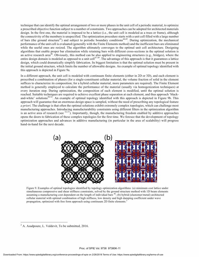
technique that can identify the optimal arrangement of two or more phases in the unit cell of a periodic material, to optimize a prescribed objective function subject to a number of constraints. Two approaches can be adopted for architected materials design. In the first one, the material is imposed to be a lattice (i.e., the unit cell is modeled as a truss or frame), although the connectivity of the members is unspecified. The optimization procedure starts with a unit cell filled with a large number of bars (the ground structure43) and subject to periodic boundary conditions44,45. During optimization, the mechanical performance of the unit cell is evaluated (generally with the Finite Elements method) and the inefficient bars are eliminated while the useful ones are resized. The algorithm ultimately converges to the optimal unit cell architecture. Designing algorithms that enable proper bar elimination while retaining bars with different cross-sections in the optimal solution is an active research area46. Obviously, this method can be also applied to engineering structures (e.g., bridges), where the entire design domain is modeled as opposed to a unit cell47-49. The advantage of this approach is that it guarantees a lattice design, which could dramatically simplify fabrication. Its biggest limitation is that the optimal solution must be present in the initial ground structure, which limits the number of allowable designs. An example of optimal topology identified with this approach is depicted in Figure 9a.
In a different approach, the unit cell is modeled with continuum finite elements (either in 2D or 3D), and each element is prescribed a combination of phases (for a single-constituent cellular material, the volume fraction of solid in the element suffices to characterize its composition; for a hybrid cellular material, more parameters are required). The Finite Element method is generally employed to calculate the performance of the material (usually via homogenization techniques) at every iteration step. During optimization, the composition of each element is modified, until the optimal solution is reached. Suitable techniques are required to achieve excellent phase separation at each element, and thus approach ‘black-and-white’ solutions50-52. An example of optimal topology identified with this approach is depicted in Figure 9b. This approach will guarantee that an enormous design space is sampled, without the need of prescribing any topological feature a priori. The challenge is that often the optimal solutions exhibit extremely complex topologies, which can challenge most manufacturing approaches. Introducing manufacturability constraints using different filters in the optimization algorithm is an active area of research (see 53-57). Importantly, though, the manufacturing freedom enabled by additive approaches opens the doors to fabrication of these complex topologies for the first time. We foresee that the development of topology optimization approaches and advances in additive manufacturing (in particular in the area of scalability) will progress hand-in-hand for the next decade.
Figure 9. Examples of optimal topologies identified by topology optimization algorithms: (a) minimum cost lattice under simultaneous compressive and shear stiffness constraints, solved by the ground structure method with 1D beam elements assuming a manufacturing cost dependent on the length of individual bars 46; (b) hybrid (elastomer/metal) architected cellular material with optimal combination of high stiffness, low density and high damping coefficient under wave propagation, optimized with free form approach using continuum 2D finite elements.2
2 A. Asadpoure, L. Valdevit, To be submitted, 2016.
Proc. of SPIE Vol. 9738 97380K-11
Downloaded From: https://www.spiedigitallibrary.org/conference-proceedings-of-spie on 2/26/2018 Terms of Use: https://www.spiedigitallibrary.org/terms-of-use

6. CONCLUSIONS AND OPPORTUNITIES FOR FUTURE DEVELOPMENTS Recent progress in the development of advanced manufacturing techniques (particularly additive processes) enables the fabrication of architected materials with almost arbitrary topological complexity and unprecedented structural bandwidth (i.e., the ratio of the largest to the smallest length scale in the architecture). Coupled with advances in topology optimization techniques, these developments enable fabrication of materials with combination of properties (mechanical and functional) unmatched by any existing monolithic material. Furthermore, the combination of high-resolution additive manufacturing approaches and thin film deposition techniques have enabled fabrication of ‘architected thin films’ with thickness as small as a few nanometers; these architected materials offer the opportunity to capitalize on dramatic nanoscale size effects on yielding and fracture in macro-scale materials. This article presented the key mechanical features of an important class of architected materials (solid and hollow lattices), reviewed the most recent developments in advanced manufacturing of these materials, and demonstrated some of their unique mechanical features. A survey of existing optimal design approaches was also provided. The development of architected materials with exceptional combinations of strength and toughness remains an active area of research, which will certainly generate exciting results over the next few years. Another key challenge in this field is the development of manufacturing processes that combine ultrahigh resolution with scalability, and that allow fabrication of multi-material lattices. Finally, most of the studies reported in this article have focused on fairly simple mechanical properties (primarily uniaxial strength and stiffness); the exploitation of the highly non-linear deformation mechanisms possible in architected materials with high structural bandwidth has barely started, and is a very promising area of research.
REFERENCES
[1] Wadley, H. N. G., “Cellular metals manufacturing,” Advanced Engineering Materials 4(10), 726–733 (2002). [2] Wadley, H. N. G., “Multifunctional periodic cellular metals,” Philosophical Transactions of the Royal Society
A: Mathematical, Physical and Engineering Sciences 364, 31–68 (2006). [3] Baldacchini, T., Three-Dimensional Microfabrication Using Two-Photon Polymerization, William Andrew
(2015). [4] Fleck, N. A., Deshpande, V. S., Ashby, M. F., “Micro-architectured materials: past, present and future,”
Proceedings of the Royal Society A 466(2121), 2495–2516 (2011). [5] Deshpande, V. S., Fleck, N. A., Ashby, M. F., “Effective properties of the octet-truss lattice material,” J Mech
Phys Solids 49(8), 1747–1769 (2001). [6] Valdevit, L., Godfrey, S. W., Schaedler, T. A., Jacobsen, A. J., Carter, W. B., “Compressive strength of hollow
microlattices: Experimental characterization, modeling, and optimal design,” Journal of Materials Research 28(17), 2461–2473 (2013).
[7] Meza, L. R., Das, S., Greer, J. R., “Strong, lightweight, and recoverable three-dimensional ceramic nanolattices.,” Science 345(6202), 1322–1326 (2014).
[8] Maiti, S. K., Ashby, M. F., GIBSON, L. J., “Fracture-Toughness of Brittle Cellular Solids,” Scripta Metallurgica 18(3), 213–217 (1984).
[9] Bauer, J., Schroer, A., Schwaiger, R., Tesari, I., Lange, C., Valdevit, L., Kraft, O., “Push-to-pull tensile testing of ultra-strong nanoscale ceramic-polymer composites made by additive manufacturing,” Extreme Mechanics Letters 3, 105–112, Elsevier Ltd (2015).
[10] Hall, E. O., “The Deformation and Ageing of Mild Steel: III Discussion of Results,” presented at Proceedings of the Physical Society, September 1951, 747–753.
[11] Petch, N. J., “The Cleavage Strength of Polycrystals,” J. Iron Steel Inst. 174, 25–28 (1953). [12] Schiøtz, J., di Tolla, F. D., Jacobsen, K. W., “Softening of nanocrystalline metals at very small grain sizes,”
Nature 391(6), 561–563 (1998). [13] Rupert, T. J., “Strain localization in a nanocrystalline metal: Atomic mechanisms and the effect of testing
conditions,” Journal of Applied Physics 114(3), 3527 (2013). [14] Detor, A., Schuh, C., “Tailoring and patterning the grain size of nanocrystalline alloys,” Acta Mater 55(1),
371–379 (2007). [15] Erb, U., “Electrodeposited nanocrystals: Synthesis, properties and industrial applications,” Nanostructured
Materials 6(5-8), 533–538 (1995). [16] Chookajorn, T., Murdoch, H. A., Schuh, C. A., “Design of Stable Nanocrystalline Alloys,” Science 337(6097),
Proc. of SPIE Vol. 9738 97380K-12
Downloaded From: https://www.spiedigitallibrary.org/conference-proceedings-of-spie on 2/26/2018 Terms of Use: https://www.spiedigitallibrary.org/terms-of-use
951–954 (2012). [17] Schaedler, T. A., Jacobsen, A. J., Torrents, A., Sorensen, A. E., Lian, J., Greer, J. R., Valdevit, L., Carter, W.
B., “Ultralight Metallic Microlattices,” Science 334(6058), 962 (2011). [18] Zheng, X., Lee, H., Weisgraber, T. H., Shusteff, M., DeOtte, J., Duoss, E. B., Kuntz, J. D., Biener, M. M., Ge,
Q., et al., “Ultralight, ultrastiff mechanical metamaterials.,” Science 344(6190), 1373–1377 (2014). [19] Rys, J., Valdevit, L., Schaedler, T. A., Jacobsen, A. J., Carter, W. B., Greer, J. R., “Fabrication and
Deformation of Metallic Glass Micro Lattices,” Advanced Engineering Materials, Wiley Online Library (2014).
[20] Griffith, A. A., “The phenomena of rupture and flow in solids,” Philosophical transactions of the royal society of … (1921).
[21] Meyers, M. A., Chawla, K. K., Mechanical behavior of materials, 1st ed., Prentice-Hall (1998). [22] Bauer, J., Schroer, A., Schwaiger, R., Tesari, I., Lange, C., Valdevit, L., Kraft, O., “Extreme Mechanics
Letters,” Extreme Mechanics Letters 3, 105–112, Elsevier Ltd (2015). [23] Wadley, H. N. G., “Multifunctional periodic cellular metals,” Philosophical Transactions of the Royal Society
A: Mathematical, Physical and Engineering Sciences 364(1838), 31 (2006). [24] Jacobsen, A. J., Barvosa-Carter, W., Nutt, S., “Micro-scale Truss Structures formed from Self-Propagating
Photopolymer Waveguides,” Advanced Materials 19(22), 3892–3896, WILEY-VCH Verlag (2007). [25] Jacobsen, A. J., Kolodziejska, J. A., Doty, R., Fink, K. D., Zhou, C., Roper, C. S., Carter, W. B.,
“Interconnected Self-Propagating Photopolymer Waveguides: An Alternative to Stereolithography for Rapid Formation of Lattice-Based Open-Cellular Materials,” presented at Proceedings of the 21st Annual International Solid Freeform Fabrication Symposium, August 2010, Austin, TX.
[26] Gibson, I., Rosen, D. W., Stucker, B., Additive Manufacturing Technologies, Springer (2009). [27] Fischer, J., Wegener, M., “Three-dimensional direct laser writing inspired by stimulated-emission-depletion
microscopy,” arXiv 1105, 5703 (2011). [28] Maloney, K. J., Roper, C. S., Jacobsen, A. J., Carter, W. B., Valdevit, L., Schaedler, T. A., “Microlattices as
architected thin films: Analysis of mechanical properties and high strain elastic recovery,” APL Mater. 1(2), 022106 (2013).
[29] Torrents, A., Schaedler, T. A., Jacobsen, A. J., Carter, W. B., Valdevit, L., “Characterization of nickel-based microlattice materials with structural hierarchy from the nanometer to the millimeter scale,” Acta Mater 60(8), 3511–3523 (2012).
[30] Jang, D., Meza, L. R., Greer, F., Greer, J. R., “Fabrication and deformation of three-dimensional hollow ceramic nanostructures.,” Nature Materials 12(10), 893–898 (2013).
[31] Bauer, J., Hengsbach, S., Tesari, I., Schwaiger, R., Kraft, O., “High-strength cellular ceramic composites with 3D microarchitecture.,” P Natl Acad Sci Usa 111(7), 2453–2458 (2014).
[32] Montemayor, L. C., Meza, L. R., Greer, J. R., “Design and Fabrication of Hollow Rigid Nanolattices via Two-Photon Lithography,” Advanced Engineering Materials 16(2), 184–189 (2013).
[33] Jacobsen, A., Barvosa-Carter, W., Nutt, S., “Compression behavior of micro-scale truss structures formed from self-propagating polymer waveguides,” Acta Mater 55(20), 6724–6733 (2007).
[34] Eckel, Z. C., Zhou, C., Martin, J. H., Jacobsen, A. J., Carter, W. B., Schaedler, T. A., “Additive manufacturing of polymer-derived ceramics.,” Science 351(6268), 58–62 (2016).
[35] Zok, F. W., Waltner, S. A., Wei, Z., Rathbun, H. J., McMeeking, R. M., Evans, A. G., “A protocol for characterizing the structural performance of metallic sandwich panels: application to pyramidal truss cores,” International Journal of Solids And Structures 41(22-23), 6249–6271 (2004).
[36] Godfrey, S. W., Valdevit, L., “A Novel Modeling Platform for Characterization and Optimal Design of Micro-Architected Materials,” presented at AIAA Structural Dynamics and Materials Conference, 13 April 2012, 1–10.
[37] Ashby, M., Evans, A., Fleck, N., GIBSON, L., Hutchinson, J., Wadley, H., Metal Foams: A Design Guide, Butterworth-Heinemann, Oxford (2000).
[38] Salari-Sharif, L., Schaedler, T. A., Valdevit, L., “Energy dissipation mechanisms in hollow metallic microlattices,” Journal of Materials Research 29(16), 1755–1770 (2014).
[39] Wang, Y.-C., Lakes, R., “Negative stiffness-induced extreme viscoelastic mechanical properties: stability and dynamics,” Philos Mag 84(35), 3785–3801 (2004).
[40] Budiansky, B., “On the minimum weights of compression structures,” International Journal of Solids And Structures 36(24), 3677–3708 (1999).
Proc. of SPIE Vol. 9738 97380K-13
Downloaded From: https://www.spiedigitallibrary.org/conference-proceedings-of-spie on 2/26/2018 Terms of Use: https://www.spiedigitallibrary.org/terms-of-use
[41] Valdevit, L., Hutchinson, J. W., Evans, A. G., “Structurally optimized sandwich panels with prismatic cores,” International Journal of Solids And Structures 41(18-19), 5105–5124 (2004).
[42] Valdevit, L., Pantano, A., Stone, H. A., Evans, A. G., “Optimal active cooling performance of metallic sandwich panels with prismatic cores,” International Journal of Heat and Mass Transfer 49(21-22), 3819–3830 (2006).
[43] Dorn, W. S., Gomory, R. E., Greenberg, H. J., “Automatic design of optimal structures,” J. Mecanique 3(1), 25–52 (1964).
[44] Sigmund, O., “Materials with prescribed constitutive parameters: An inverse homogenization problem,” International Journal of Solids And Structures 31, 2313–2329 (1994).
[45] Asadpoure, A., Valdevit, L., “International Journal of Solids and Structures,” International Journal of Solids And Structures 60-61(C), 1–16, Elsevier Ltd (2015).
[46] Asadpoure, A., Guest, J. K., Valdevit, L., “Incorporating fabrication cost into topology optimization of discrete structures and lattices,” Structural and Multidisciplinary Optimization 51(2), 385–396 (2014).
[47] Pedersen, P., Topology Optimization of Three-Dimensional Trusses, Springer Netherlands (1993). [48] Ohsaki, M., Katoh, N., “Topology optimization of trusses with stress and local constraints on nodal stability
and member intersection,” Structural and Multidisciplinary Optimization 29(3), 190–197 (2005). [49] Achtziger, W., Stolpe, M., “Truss topology optimization with discrete design variables—Guaranteed global
optimality and benchmark examples,” Structural and Multidisciplinary Optimization 34(1), 1–20, Springer-Verlag (2007).
[50] Bendsoe, M. P., “Optimal shape design as a material distribution problem,” Structural Optimization 1, 193–202 (1989).
[51] Rozvany, G. I. N., Zhou, M., Birker, T., “Generalized shape optimization without homogenization,” Structural Optimization (ISSN 0934-4373) 4, 250–252 (1992).
[52] Stolpe, M., Svanberg, K., “An alternative interpolation scheme for minimum compliance topology optimization,” Structural and Multidisciplinary Optimization (2001).
[53] Sigmund, O., Torquato, S., “Design of materials with extreme thermal expansion using a three-phase topology optimization method,” J Mech Phys Solids 45, 1037–1067 (1997).
[54] Bruns, T. E., Tortorelli, D. A., “An element removal and reintroduction strategy for the topology optimization of structures and compliant mechanisms,” Int J Numer Meth Eng 57(10), 1413–1430, John Wiley & Sons, Ltd. (2003).
[55] Guest, J. K., Prevost, J. H., Belytschko, T., “Achieving minimum length scale in topology optimization using nodal design variables and projection functions,” Int J Numer Meth Eng 61(2), 238–254 (2004).
[56] Wang, M. Y., Wang, S., “Bilateral filtering for structural topology optimization,” Int J Numer Meth Eng 63(13), 1911–1938 (2005).
[57] Sigmund, O., “Morphology-based black and white filters for topology optimization,” Structural and Multidisciplinary Optimization 33(4-5), 401–424 (2007).
Proc. of SPIE Vol. 9738 97380K-14
Downloaded From: https://www.spiedigitallibrary.org/conference-proceedings-of-spie on 2/26/2018 Terms of Use: https://www.spiedigitallibrary.org/terms-of-use