probo pr70 pr70-dl pr120 pr120-dl · lc020508 - life - 10/2008 probo pr70 pr70-dl pr120 pr120-dl...
TRANSCRIPT
LC020508 - LIFE - 10/2008
PROBO PR70 PR70-DLPR120 PR120-DL
MOTORIDUTTORE ELETTROMECCANICO IRREVERSIBILE PER PORTE SEZIONALI E BASCULANTIISTRUZIONI E AVVERTENZE PER L’INSTALLAZIONE, L’USO E LA MANUTENZIONE.
IRREVERSIBLE ELECTRO-MECHANICAL OPERATOR FOR SECTIONAL AND UP-AND-OVER DOORSINSTRUCTIONS AND INDICATIONS FOR INSTALLATION, USE AND MAINTENANCE.
MOTO-REDUCTEUR ELECTROMECANIQUE IRREVERSIBILE POUR PORTES SECTIONNELLES ET BASCULANTESINSTRUCTIONS ET CONSEILS POUR L’INSTALLATION, L’EMPLOI ET L’ENTRETIEN.
MOTORREDUCTOR ELECTROMECÁNICO IRREVERSIBLE PARA PUERTAS SECCIONALES Y BASCULANTESINSTRUCCIONES Y ADVERTENCIAS PARA LA INSTALACIÓN, EL USO Y EL MANTENIMIENTO.
CENTRAIS DE COMANDO PARA PORTÕES DE BATENTEINSTRUÇÕES E ADVERTÊNCIAS PARA A INSTALAÇÃO, USO E MANUTENÇÃO.
ELEKTROMECHANISCHER TORANTRIEB PROBO FÜR SCHWING- UND GARAGENTOREANLEITUNGEN UND HINWEISE FÜR INSTALLATION, GEBRAUCH UND WARTUNG.
MOTOREDUKTOR ELEKTROMECHANICZNY NIEZWROTNY DO BRAM SEKCYJNYCH I WAHADŁOWYCHINSTRUKCJE I WSKAZÓWKI DOTYCZĄCE MONTAŻU, UŻYTKOWANIA I KONSERWACJI.
НЕРЕВЕРСИВНЫЙ ЭЛЕКТРОМЕХАНИЧЕСКИЙ ПОТОЛОЧНЫЙ ПРИВОД ДЛЯ СЕКЦИОННЫХ ИПОДЪЕМНО-ПОВОРОТНЫХ ВОРОТИНСТРУКЦИИ, ЗАМЕЧАНИЯ ПО МОНТАЖУ, ЭКСПЛУАТАЦИИ И ТЕХНИЧЕСКОМУ ОБСЛУЖИВАНИЮ.
ELEKTROMECHANICKÝ NEREVERZNÝ POHON PROBO PRE SEKČNÉ A VÝKLOPNÉ GARÁŽOVÉ BRÁNYUPOZORNENIA A NÁVOD NA INŠTALÁCIU, POUŽÍVANIE A ÚDRŽBU.
VEZÉRLŐEGYSÉG 24 V-OS MOTOROKHOZSZERELÉSI UTASÍTÁSOK ÉS FIGYELMEZTETÉSEK, HASZNÁLAT ÉS KARBANTARTÁS.
ŘÍDÍCÍ JEDNOTKA POHONU PRO AUTOMATIZACI VYBAVENOU 24 V MOTORYPOKYNY A VAROVÁNÍ PRO INSTALACI, POUŽITÍ A ÚDRŽBU.
1 A
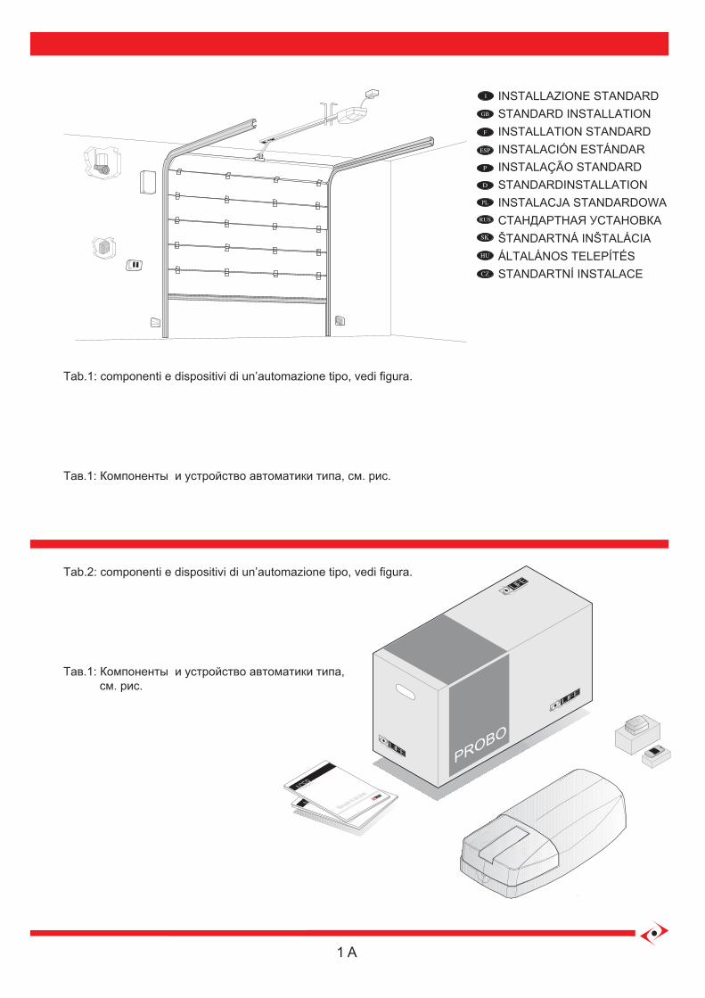
Tab.2: componenti e dispositivi di un’automazione tipo, vedi figura.
Тав.1: Компоненты и устройство автоматики типа, см. рис.
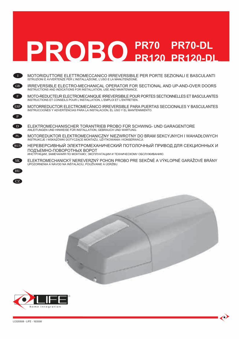
Tab.1: componenti e dispositivi di un’automazione tipo, vedi figura.
Тав.1: Компоненты и устройство автоматики типа, см. рис.
ACER
Manuale di istruzioni
ACER
Manuale di istruzioni
PROBO
INSTALLAZIONE STANDARDSTANDARD INSTALLATIONINSTALLATION STANDARDINSTALACIÓN ESTÁNDAR
ŠTANDARTNÁ INŠTALÁCIAÁLTALÁNOS TELEPÍTÉSSTANDARTNÍ INSTALACE
INSTALAÇÃO STANDARDSTANDARDINSTALLATIONINSTALACJA STANDARDOWAСТАНДАРТНАЯ УСТАНОВКА
2 A
10 11
1513
4
16 17
8 9
76
145
2
1
3
1
12
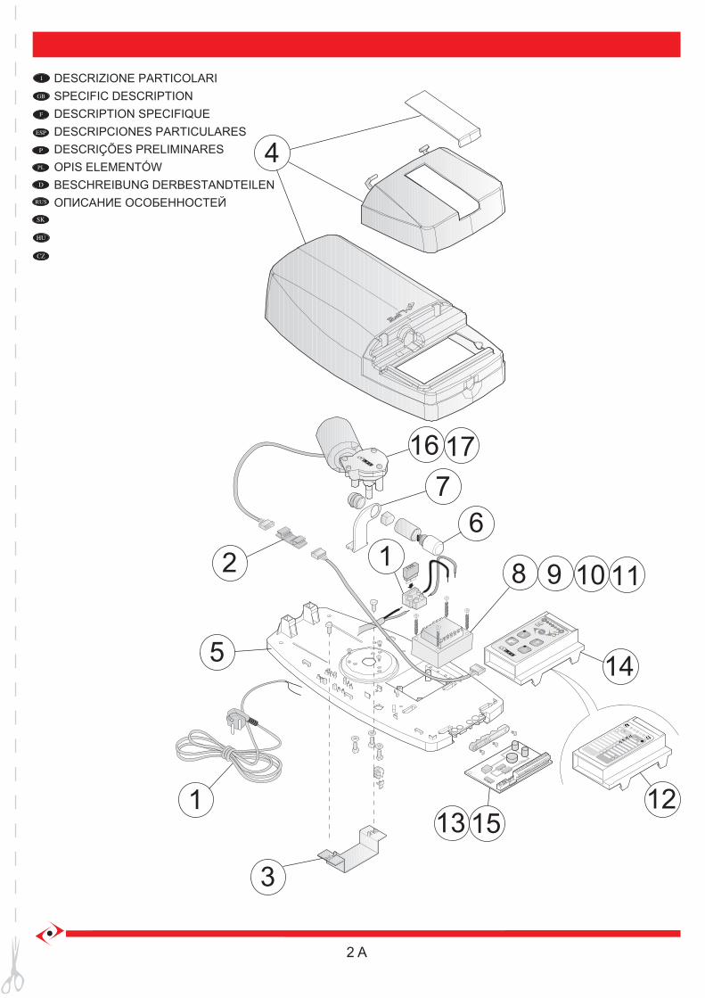
DESCRIZIONE PARTICOLARISPECIFIC DESCRIPTIONDESCRIPTION SPECIFIQUEDESCRIPCIONES PARTICULARES
ŠTANDARTNÁ INŠTALÁCIAÁLTALÁNOS TELEPÍTÉSSTANDARTNÍ INSTALACE
DESCRIÇÕES PRELIMINARESOPIS ELEMENTÓWBESCHREIBUNG DERBESTANDTEILENОПИСАНИЕ ОСОБЕННОСТЕЙ
HSIL
GN
E
MANUAL DESTINED TO PROFESSIONAL FITTERS ONLYUnder applicable law, installation may only be performed by professional fitters.
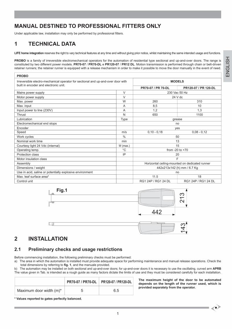
1 TECHNICAL DATALIFE home integration reserves the right to vary technical features at any time and without giving prior notice, whilst maintaining the same intended usage and functions.
PROBO is a family of irreversible electromechanical operators for the automation of residential type sectional and up-and-over doors. The range is constituted by two different power models. PR70-07 / PR70-DL e PR120-07 / PR12 DL. Motion transmission is performed through chain or belt-driven retainer runners; the retainer runner is equipped with a release mechanism in order to make it possible to move the door manually in the event of need.
Irreversible electro-mechanical operator for sectional and up-and-over door with built in encoder and electronic unit.
MODELS
PROBO
230 Vac 50 HzMains power supply 24 V dcMotor power supply
greaseLubricationnoElectromechanical end stopsyesEncoder
50Work cycles13Nominal work time15Courtesy light 24 Vdc (internal)
from -20 to +70Operating temp.
Horizontal ceiling-mounted on dedicated runnerAssembly442x213x142 (h) mm / 6.7 KgDimensions / weight
noUse in acid, saline or potentially explosive environment
20Protection classFMotor insulation class
Speed
Max. powerMax. inputInput power to line (230V)Thrust
Max. leaf surface area*
PR70-07 / PR 70-DL
0,10 - 0,18
2608,51,2650
11.5RG1 24P / RG1 24 DL
VV
Type
%min
W (max.)°CIP
m/s
WAAN
Control unit
0,08 - 0,12
310101,3
1100
18RG1 24P / RG1 24 DL
PR120-07 / PR 120-DL
Fig.1
2 INSTALLATION
2.1 Preliminary checks and usage restrictionsBefore commencing installation, the following preliminary checks must be performed:a) The area in which the automation is installed must provide adequate space for performing maintenance and manual release operations. Check the total dimensions by referring to fig. 1, and the manuale provided.b) The automation may be installed on both sectional and up-and-over doors; for up-and-over doors it is necessary to use the oscillating, curved arm APRBThe value given in Tab. is intended as a rough guide as many factors dictate the limits of use and they must be considered carefully for each installation.
The maximum height of the door to be automateddepends on the length of the runner used, which isprovided separately from the operator.
* Values reported to gates perfectly balanced.
442
143
213
PR70-07 / PR70-DL PR120-07 / PR120-DL
5Maximum door width (m)* 6.5
1
2
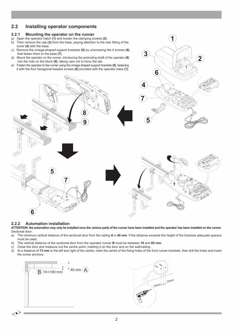
2.2 Installing operator components
2.2.1 Mounting the operator on the runnera) Open the operator hatch (1) and loosen the clamping screws (2).b) Then remove the cap (3) from the base, paying attention to the rear fitting of the cover (4) with the base.c) Remove the omega-shaped support brackets (5) by unscrewing the 4 screws (6) that fasten them to the base (7).d) Mount the operator on the runner, introducing the protruding shaft of the operator (8) into the hole on the block (9), taking care not to force the tab.e) Fasten the operator to the runner using the omega-shaped support brackets (5), fastening it with the four hexagonal-headed screws (6) provided with the operator base (7).
2.2.2 Automation installationATTENTION: the automation may only be installed once the various parts of the runner have been installed and the operator has been installed on the runner.Sectional door:a) The minimum vertical distance of the sectional door from the ceiling A is 40 mm. If the distance exceeds the height of the brackets adequate spacers must be used.b) The vertical distance of the sectional door from the operator runner B must be between 10 and 65 mm.c) Close the door and measure out the centre point, marking it on the door and on the wall/ceiling.d) At a distance of 73 mm to the left and right of the centre, mark the centre of the fixing holes of the front runner brackets, then drill the holes and insert the screw anchors.
6
57
98
7
5
1
3
6
4
2
B A40 mm10 : 100 mm
73mm
73mm
HSIL
GN
E
3
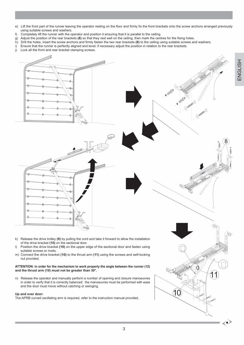
e) Lift the front part of the runner leaving the operator resting on the floor and firmly fix the front brackets onto the screw anchors arranged previously using suitable screws and washers.f) Completely lift the runner with the operator and position it ensuring that it is parallel to the ceiling.g) Adjust the position of the rear brackets (8) so that they rest well on the ceiling, then mark the centres for the fixing holes.h) Drill the holes, insert the screw anchors and firmly fasten the two rear brackets (8) to the ceiling using suitable screws and washers.i) Ensure that the runner is perfectly aligned and level; if necessary adjust the position in relation to the rear brackets.j) Lock all the front and rear bracket clamping screws.
k) Release the drive trolley (9) by pulling the cord and take it forward to allow the installation of the drive bracket (10) on the sectional door.l) Position the drive bracket (10) on the upper edge of the sectional door and fasten using suitable screws or rivets.m) Connect the drive bracket (10) to the thrust arm (11) using the screws and self-locking nut provided.
ATTENTION: in order for the mechanism to work properly the angle between the runner (12) and the thrust arm (10) must not be greater than 30°.
n) Release the operator and manually perform a number of opening and closure manoeuvres in order to verify that it is correctly balanced: the manoeuvres must be performed with ease and the door must move without catching or swinging.
Up and over door:The APRB curved oscillating arm is required, refer to the instruction manual provided.
8
10
�0
�
11�
4
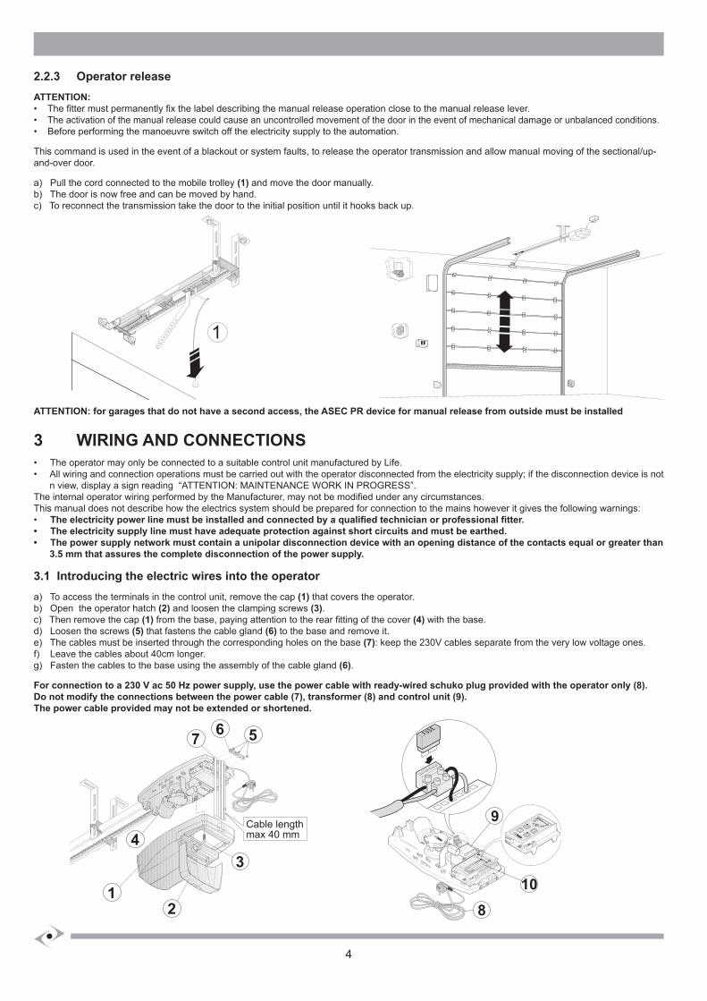
2.2.3 Operator releaseATTENTION:• The fitter must permanently fix the label describing the manual release operation close to the manual release lever.• The activation of the manual release could cause an uncontrolled movement of the door in the event of mechanical damage or unbalanced conditions.• Before performing the manoeuvre switch off the electricity supply to the automation.
This command is used in the event of a blackout or system faults, to release the operator transmission and allow manual moving of the sectional/up-and-over door.
a) Pull the cord connected to the mobile trolley (1) and move the door manually.b) The door is now free and can be moved by hand.c) To reconnect the transmission take the door to the initial position until it hooks back up.
ATTENTION: for garages that do not have a second access, the ASEC PR device for manual release from outside must be installed
3 WIRING AND CONNECTIONS• The operator may only be connected to a suitable control unit manufactured by Life. • All wiring and connection operations must be carried out with the operator disconnected from the electricity supply; if the disconnection device is not n view, display a sign reading “ATTENTION: MAINTENANCE WORK IN PROGRESS”.The internal operator wiring performed by the Manufacturer, may not be modified under any circumstances.This manual does not describe how the electrics system should be prepared for connection to the mains however it gives the following warnings:• The electricity power line must be installed and connected by a qualified technician or professional fitter.• The electricity supply line must have adequate protection against short circuits and must be earthed. • The power supply network must contain a unipolar disconnection device with an opening distance of the contacts equal or greater than 3.5 mm that assures the complete disconnection of the power supply.
3.1 Introducing the electric wires into the operatora) To access the terminals in the control unit, remove the cap (1) that covers the operator.b) Open the operator hatch (2) and loosen the clamping screws (3).c) Then remove the cap (1) from the base, paying attention to the rear fitting of the cover (4) with the base.d) Loosen the screws (5) that fastens the cable gland (6) to the base and remove it.e) The cables must be inserted through the corresponding holes on the base (7): keep the 230V cables separate from the very low voltage ones.f) Leave the cables about 40cm longer.g) Fasten the cables to the base using the assembly of the cable gland (6).
For connection to a 230 V ac 50 Hz power supply, use the power cable with ready-wired schuko plug provided with the operator only (8).Do not modify the connections between the power cable (7), transformer (8) and control unit (9).The power cable provided may not be extended or shortened.
11
Cable lengthmax 40 mm
567
4
12
3
8
9
10
HSIL
GN
E
5
Declaration of conformity
under Directive 98/37/EC, appendix II, part B (Manufacturer’s Declaration of CE Conformity)
LIFE Home IntegrationVia 1 Maggio, 37
31043 FONTANELLE (TV) – Italy
declares that the following product:
PROBO PR70 PR70-DL PR120 PR120-DLsatisfies the essential requisites established in the following directives:
• Low voltage directive 73/23/EEC and subsequent amendments,• Electromagnetic compatibility directive 89/336/EEC and subsequent amendments,• Radio and telecommunications equipment directive 1999/5/EC and subsequent amendments.
and satisfies the following standards:
• EN 12445:2000 Industrial, commercial and garage doors and gates – Safety in the usage of motorised doors – testing methods• EN 12453: Industrial, commercial and garage doors and gates – Safety in the usage of motorised doors – Requisites• EN 60204-1:1997 Machinery safety – Electric equipment of the machine – Part 1: general rules.
The Manufacturer also declares that it is not permitted for the abovementioned components to be used until such time as the system in which they are incorporated is declared conform to directive 98/37/EC.
Fontanelle 20/10/2007 Name of Signor: Faustino Lucchetta Position: Managing Director Signature: __________________
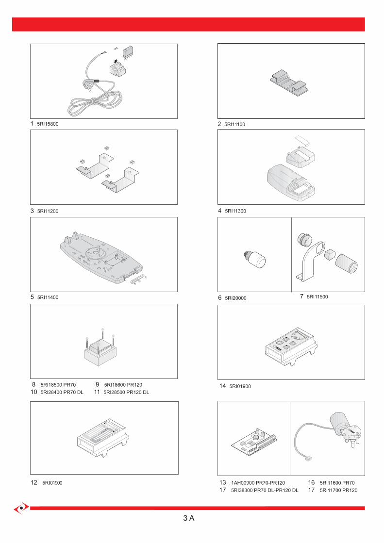
1 5RI15800 2 5RI11100
3 5RI11200 4 5RI11300
5 5RI11400 6 5RI20000 7 5RI11500
8 5RI18500 PR70 9 5RI18600 PR12010 5RI28400 PR70 DL 11 5RI28500 PR120 DL
14 5RI01900
12 5RI01900 16 5RI11600 PR70 17 5RI11700 PR120
13 1AH00900 PR70-PR120 17 5RI38300 PR70 DL-PR120 DL
3 A