problem solving guide of the 11ak19 …archive.espec.ws/files/ak19 problem solving...
TRANSCRIPT
PROBLEM SOLVING GUIDE OF THE 11AK19 MAINBOARD : From the “Problem Solving Guide” menu you select a chassis and see the “Problem Solving Guide” page designed for that chassis. In these pages, you can see some well-known and mostly faced problems and some hints to detect the source of the problem. If the conditions in the “Descriptions” parts are the situations that you face up with, then beside that description , you can see the “Defected components” to be replaced for solving the problem.
Product Circuit Diagram Circuit Description
Change BulletinHardware &
Software Opt. Service ManualProblem Solving
GuideExploded Views
NR PROBLEM DESCRIPTIONS DEFECTED COMPONENTS1 No sound
(mono)1-Speakers 2-IC100 pin 5: -12.5VDC 3-IC100 pin 7: +12.5VDC 4-IC100 pin 2: +12.5VDC 5-IC100 pin 9: Sound signal (Scop) 6-IC401 pin 15: Sound signal (Scop) 7-IC401 pin 55:Sound signal (Scop)
Speakers,IC100,IC502,IC401, Q402
2 No sound (stereo)
1-Speakers 2-IC100 pin 5: -12.5VDC 3-IC100 pin 7: +12.5VDC 4-IC100 pin 2: +12.5VDC 5-IC100 pin 9: Sound signal (Scop) 6-IC100 pin 1:Sound signal (Scop) 7-PL404 pin 4: Sound signal (Scop) 8-PL404 pin 5: Sound signal (Scop)
Speakers,Sound Board,IC100,IC502
3 No sound (Secam L mono)
1-IC501 pin 9 :0V 2-IC501 pin 18 :5V 3-IC401 pin 2: Sound signal (Scop) 4-IC402 pin 8: Sound signal (Scop)
IC402
4 No sound ın the Nicam mode
IC502
5 Sound level is low (mono)
1-IC401 pin 55: 3V DC 2-500mVpp audio (Scop) 3-100mVpp RF signal (Scop)
Q401,IC100
Seite 1 von 5ARIZALAR1
10.09.2002https://www.vestelservice.com/service/problem19.asp
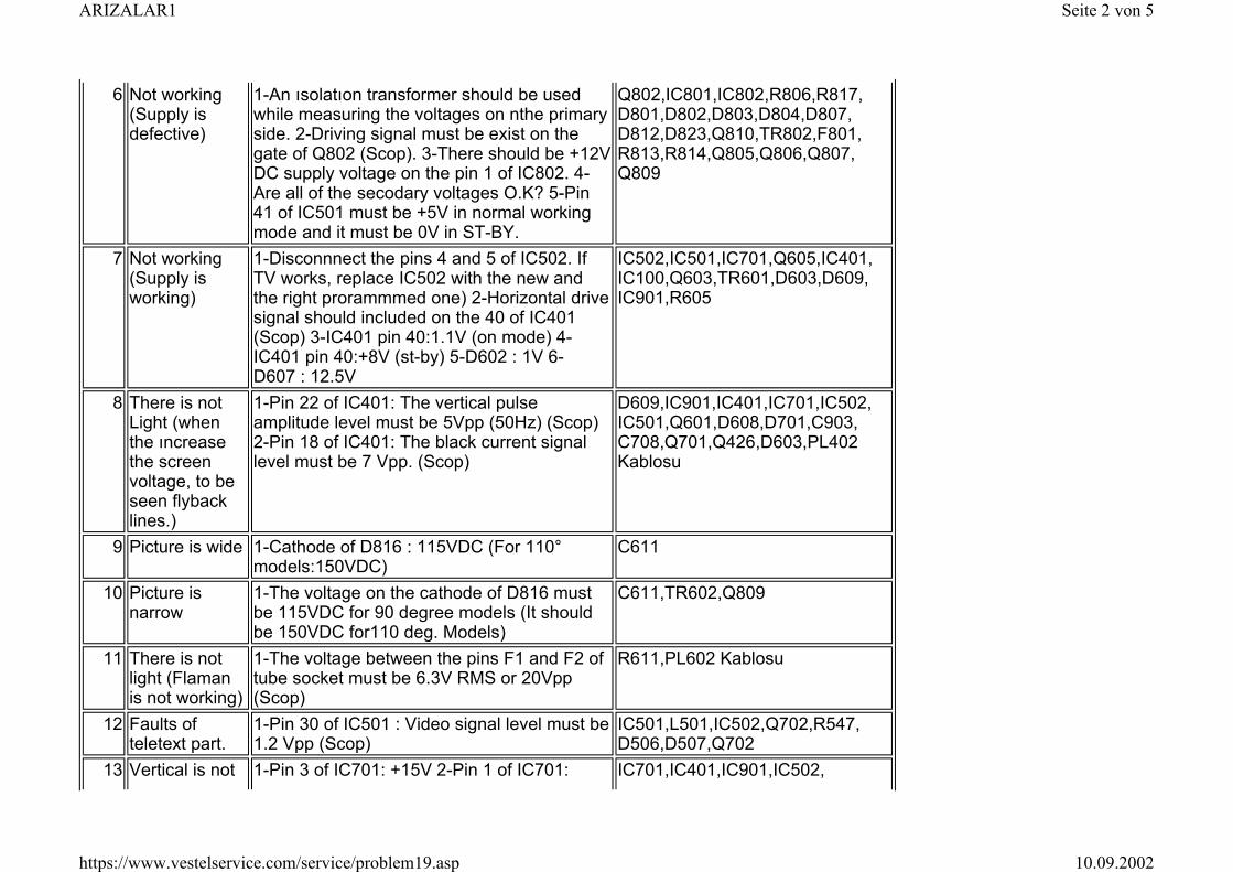
6 Not working (Supply is defective)
1-An ısolatıon transformer should be used while measuring the voltages on nthe primary side. 2-Driving signal must be exist on the gate of Q802 (Scop). 3-There should be +12V DC supply voltage on the pin 1 of IC802. 4-Are all of the secodary voltages O.K? 5-Pin 41 of IC501 must be +5V in normal working mode and it must be 0V in ST-BY.
Q802,IC801,IC802,R806,R817, D801,D802,D803,D804,D807, D812,D823,Q810,TR802,F801, R813,R814,Q805,Q806,Q807, Q809
7 Not working (Supply is working)
1-Disconnnect the pins 4 and 5 of IC502. If TV works, replace IC502 with the new and the right prorammmed one) 2-Horizontal drive signal should included on the 40 of IC401 (Scop) 3-IC401 pin 40:1.1V (on mode) 4-IC401 pin 40:+8V (st-by) 5-D602 : 1V 6-D607 : 12.5V
IC502,IC501,IC701,Q605,IC401, IC100,Q603,TR601,D603,D609, IC901,R605
8 There is not Light (when the ıncrease the screen voltage, to be seen flyback lines.)
1-Pin 22 of IC401: The vertical pulse amplitude level must be 5Vpp (50Hz) (Scop) 2-Pin 18 of IC401: The black current signal level must be 7 Vpp. (Scop)
D609,IC901,IC401,IC701,IC502, IC501,Q601,D608,D701,C903, C708,Q701,Q426,D603,PL402 Kablosu
9 Picture is wide 1-Cathode of D816 : 115VDC (For 110° models:150VDC)
C611
10 Picture is narrow
1-The voltage on the cathode of D816 must be 115VDC for 90 degree models (It should be 150VDC for110 deg. Models)
C611,TR602,Q809
11 There is not light (Flaman is not working)
1-The voltage between the pins F1 and F2 of tube socket must be 6.3V RMS or 20Vpp (Scop)
R611,PL602 Kablosu
12 Faults of teletext part.
1-Pin 30 of IC501 : Video signal level must be 1.2 Vpp (Scop)
IC501,L501,IC502,Q702,R547, D506,D507,Q702
13 Vertical is not 1-Pin 3 of IC701: +15V 2-Pin 1 of IC701: IC701,IC401,IC901,IC502,
Seite 2 von 5ARIZALAR1
10.09.2002https://www.vestelservice.com/service/problem19.asp
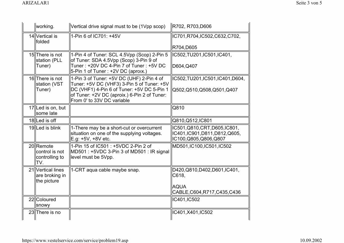
working. Vertical drive signal must to be (1Vpp scop) R702, R703,D606
14 Vertical is folded
1-Pin 6 of IC701: +45V IC701,R704,IC502,C632,C702,
R704,D605 15 There is not
station (PLL Tuner)
1-Pin 4 of Tuner: SCL 4.5Vpp (Scop) 2-Pin 5 of Tuner: SDA 4.5Vpp (Scop) 3-Pin 9 of Tuner : +20V DC 4-Pin 7 of Tuner : +5V DC 5-Pin 1 of Tuner : +2V DC (aproıx.)
IC502,TU201,IC501,IC401,
D604,Q407
16 There is not station (VST Tuner)
1-Pin 3 of Tuner: +5V DC (UHF) 2-Pin 4 of Tuner: +5V DC (VHF3) 3-Pin 5 of Tuner: +5V DC (VHF1) 4-Pin 6 of Tuner: +5V DC 5-Pin 1 of Tuner: +2V DC (aproix.) 6-Pin 2 of Tuner: From 0' to 33V DC variable
IC502,TU201,IC501,IC401,D604,
Q502,Q510,Q508,Q501,Q407
17 Led is on, but some late
Q810
18 Led is off Q810,Q512,IC80119 Led is blink 1-There may be a short-cut or overcurrent
situation on one of the supplying voltages. E.g: +5V, +8V etc.
IC501,Q810,CRT,D605,IC801, IC401,IC901,D811,D812,Q605, IC100,Q805,Q806,Q807
20 Remote control is not controlling to TV.
1-Pin 15 of IC501 : +5VDC 2-Pin 2 of MD501 : +5VDC 3-Pin 3 of MD501 : IR signal level must be 5Vpp.
MD501,IC100,IC501,IC502
21 Vertical lines are broking in the picture
1-CRT aqua cable maybe snap. D420,Q810,D402,D601,IC401, C618,
AQUA CABLE,C604,R717,C435,C436
22 Coloured snowy
IC401,IC502
23 There is no IC401,X401,IC502
Seite 3 von 5ARIZALAR1
10.09.2002https://www.vestelservice.com/service/problem19.asp
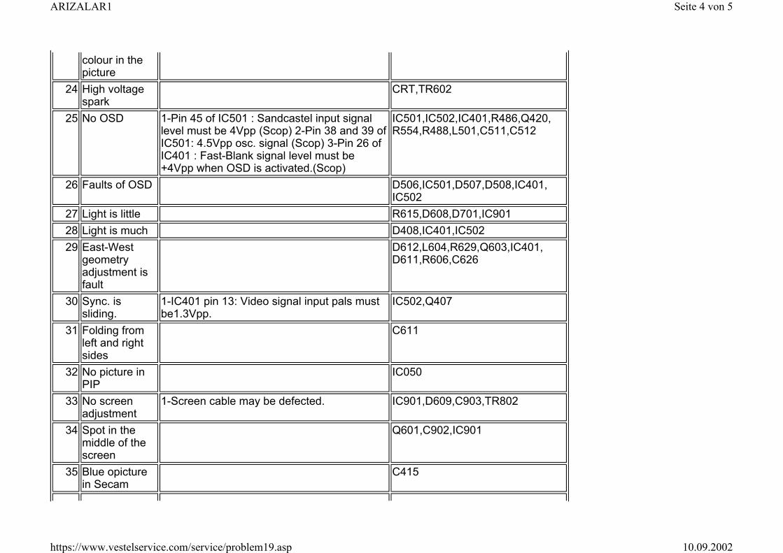
colour in the picture
24 High voltage spark
CRT,TR602
25 No OSD 1-Pin 45 of IC501 : Sandcastel input signal level must be 4Vpp (Scop) 2-Pin 38 and 39 of IC501: 4.5Vpp osc. signal (Scop) 3-Pin 26 of IC401 : Fast-Blank signal level must be +4Vpp when OSD is activated.(Scop)
IC501,IC502,IC401,R486,Q420, R554,R488,L501,C511,C512
26 Faults of OSD D506,IC501,D507,D508,IC401, IC502
27 Light is little R615,D608,D701,IC90128 Light is much D408,IC401,IC50229 East-West
geometry adjustment is fault
D612,L604,R629,Q603,IC401, D611,R606,C626
30 Sync. is sliding.
1-IC401 pin 13: Video signal input pals must be1.3Vpp.
IC502,Q407
31 Folding from left and right sides
C611
32 No picture in PIP
IC050
33 No screen adjustment
1-Screen cable may be defected. IC901,D609,C903,TR802
34 Spot in the middle of the screen
Q601,C902,IC901
35 Blue opicture in Secam
C415
Seite 4 von 5ARIZALAR1
10.09.2002https://www.vestelservice.com/service/problem19.asp
Last Updated on 11.02.1999 By VESTEL
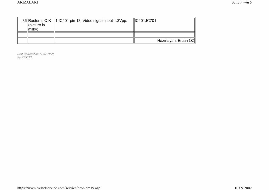
36 Raster is O.K (picture is milky)
1-IC401 pin 13: Video signal input 1.3Vpp. IC401,IC701
Hazırlayan: Ercan ÖZ
Seite 5 von 5ARIZALAR1
10.09.2002https://www.vestelservice.com/service/problem19.asp