principal stresses
DESCRIPTION
strength of materialTRANSCRIPT
© 2012 The McGraw-Hill Companies, Inc. All rights reserved.
MECHANICS OF MATERIALS
Six
thE
ditio
n
Beer • Johnston • DeWolf • Mazurek
8- 1
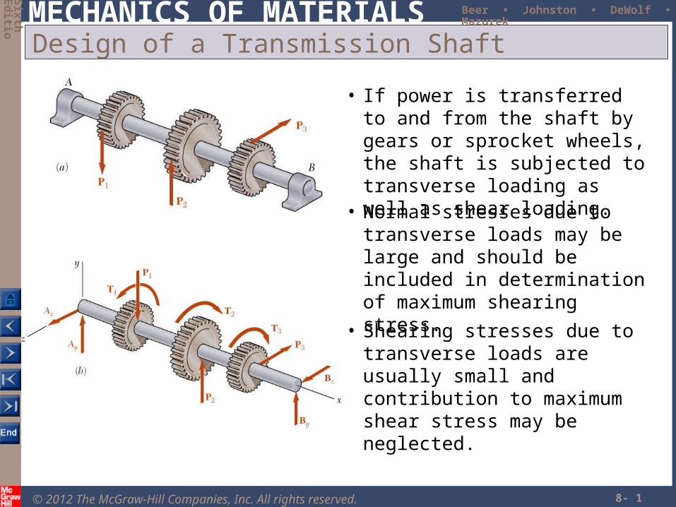
Design of a Transmission Shaft
• If power is transferred to and from the shaft by gears or sprocket wheels, the shaft is subjected to transverse loading as well as shear loading.
• Normal stresses due to transverse loads may be large and should be included in determination of maximum shearing stress.
• Shearing stresses due to transverse loads are usually small and contribution to maximum shear stress may be neglected.
© 2012 The McGraw-Hill Companies, Inc. All rights reserved.
MECHANICS OF MATERIALS
Six
thE
ditio
n
Beer • Johnston • DeWolf • Mazurek
8- 2
Design of a Transmission Shaft
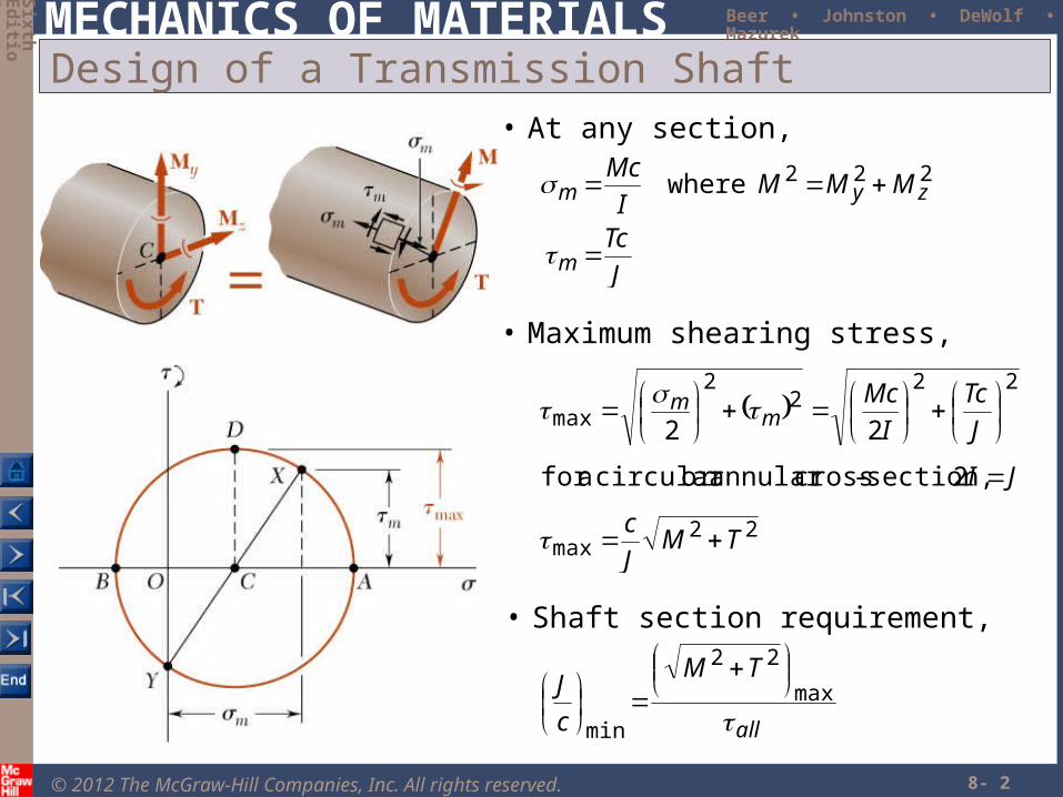
• Shaft section requirement,
all
TM
c
J
max
22
min
• Maximum shearing stress,
22max
222
2
max
2 section,-crossannular or circular afor
22
TMJ
c
JI
J
Tc
I
Mcm
m
• At any section,
J
Tc
MMMI
Mc
m
zym
222where
© 2012 The McGraw-Hill Companies, Inc. All rights reserved.
MECHANICS OF MATERIALS
Six
thE
ditio
n
Beer • Johnston • DeWolf • Mazurek
8- 3
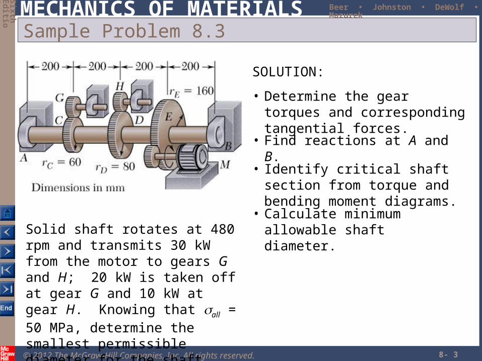
Sample Problem 8.3
Solid shaft rotates at 480 rpm and transmits 30 kW from the motor to gears G and H; 20 kW is taken off at gear G and 10 kW at gear H. Knowing that all = 50 MPa, determine the smallest permissible diameter for the shaft.
SOLUTION:
• Determine the gear torques and corresponding tangential forces.
• Find reactions at A and B.
• Identify critical shaft section from torque and bending moment diagrams.
• Calculate minimum allowable shaft diameter.
© 2012 The McGraw-Hill Companies, Inc. All rights reserved.
MECHANICS OF MATERIALS
Six
thE
ditio
n
Beer • Johnston • DeWolf • Mazurek
8- 4
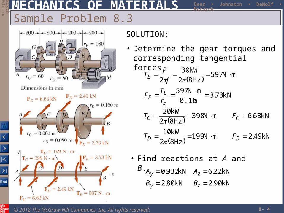
Sample Problem 8.3SOLUTION:
• Determine the gear torques and corresponding tangential forces.
kN49.2mN199Hz82
kW10
kN63.6mN398Hz82
kW20
kN73.3m0.16
mN597
mN597Hz82
kW30
2
DD
CC
E
EE
E
FT
FT
r
TF
f
PT
• Find reactions at A and B.
kN90.2kN80.2
kN22.6kN932.0
zy
zy
BB
AA
© 2012 The McGraw-Hill Companies, Inc. All rights reserved.
MECHANICS OF MATERIALS
Six
thE
ditio
n
Beer • Johnston • DeWolf • Mazurek
8- 5
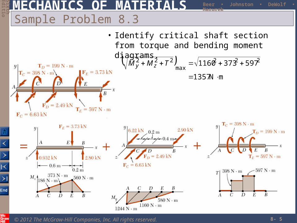
Sample Problem 8.3• Identify critical shaft section from torque and
bending moment diagrams.
mN1357
5973731160 222max
222
TMM zy
© 2012 The McGraw-Hill Companies, Inc. All rights reserved.
MECHANICS OF MATERIALS
Six
thE
ditio
n
Beer • Johnston • DeWolf • Mazurek
8- 6
Sample Problem 8.3
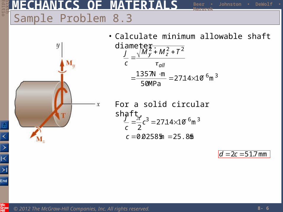
• Calculate minimum allowable shaft diameter.
36
222
m1014.27MPa50
mN 1357
all
zy TMM
c
J
mm 7.512 cd
m25.85m02585.0
m1014.272
363
c
cc
J
For a solid circular shaft,
© 2012 The McGraw-Hill Companies, Inc. All rights reserved.
MECHANICS OF MATERIALS
Six
thE
ditio
n
Beer • Johnston • DeWolf • Mazurek
8- 7
Stresses Under Combined Loadings
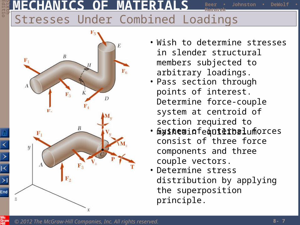
• Wish to determine stresses in slender structural members subjected to arbitrary loadings.
• Pass section through points of interest. Determine force-couple system at centroid of section required to maintain equilibrium.
• System of internal forces consist of three force components and three couple vectors.
• Determine stress distribution by applying the superposition principle.
© 2012 The McGraw-Hill Companies, Inc. All rights reserved.
MECHANICS OF MATERIALS
Six
thE
ditio
n
Beer • Johnston • DeWolf • Mazurek
8- 8
Stresses Under Combined Loadings
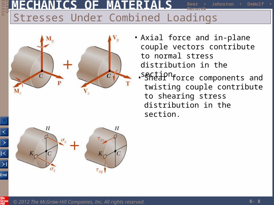
• Axial force and in-plane couple vectors contribute to normal stress distribution in the section.
• Shear force components and twisting couple contribute to shearing stress distribution in the section.
© 2012 The McGraw-Hill Companies, Inc. All rights reserved.
MECHANICS OF MATERIALS
Six
thE
ditio
n
Beer • Johnston • DeWolf • Mazurek
8- 9
Stresses Under Combined Loadings
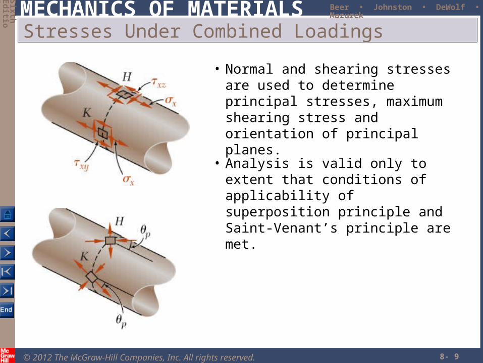
• Normal and shearing stresses are used to determine principal stresses, maximum shearing stress and orientation of principal planes.
• Analysis is valid only to extent that conditions of applicability of superposition principle and Saint-Venant’s principle are met.
© 2012 The McGraw-Hill Companies, Inc. All rights reserved.
MECHANICS OF MATERIALS
Six
thE
ditio
n
Beer • Johnston • DeWolf • Mazurek
8- 10
Sample Problem 8.5
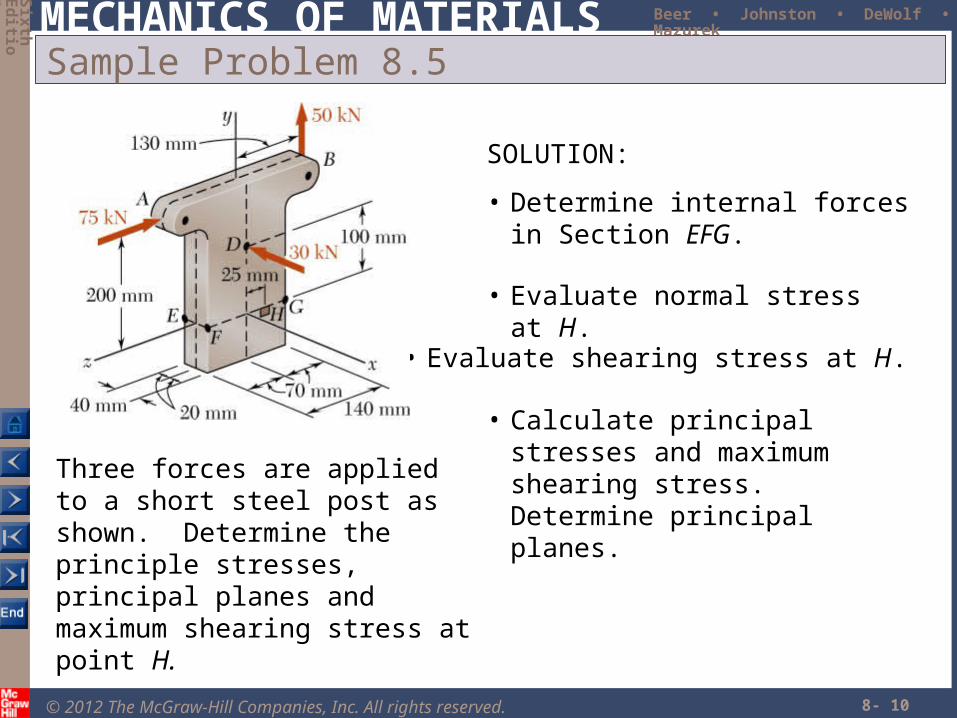
Three forces are applied to a short steel post as shown. Determine the principle stresses, principal planes and maximum shearing stress at point H.
SOLUTION:
• Determine internal forces in Section EFG.
• Calculate principal stresses and maximum shearing stress. Determine principal planes.
• Evaluate shearing stress at H.
• Evaluate normal stress at H.
© 2012 The McGraw-Hill Companies, Inc. All rights reserved.
MECHANICS OF MATERIALS
Six
thE
ditio
n
Beer • Johnston • DeWolf • Mazurek
8- 11
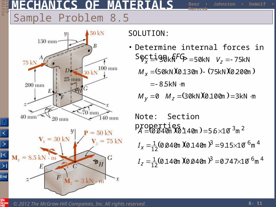
Sample Problem 8.5SOLUTION:
• Determine internal forces in Section EFG.
mkN3m100.0kN300
mkN5.8
m200.0kN75m130.0kN50
kN75kN50kN 30
zy
x
zx
MM
M
VPV
Note: Section properties,
463121
463121
23
m10747.0m040.0m140.0
m1015.9m140.0m040.0
m106.5m140.0m040.0
z
x
I
I
A
© 2012 The McGraw-Hill Companies, Inc. All rights reserved.
MECHANICS OF MATERIALS
Six
thE
ditio
n
Beer • Johnston • DeWolf • Mazurek
8- 12
Sample Problem 8.5
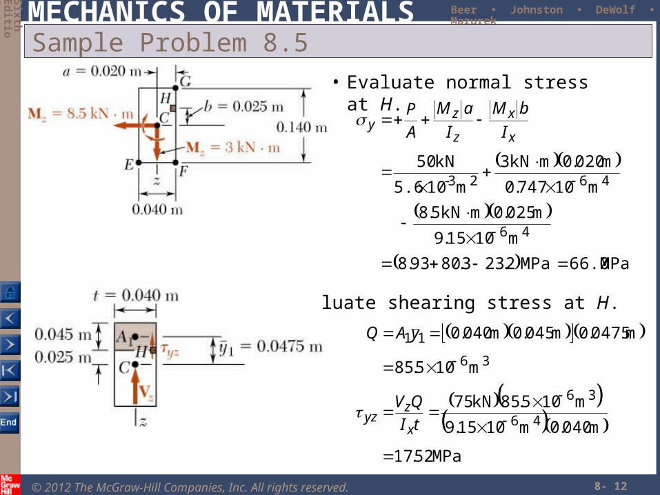
• Evaluate normal stress at H.
MPa66.0MPa2.233.8093.8
m1015.9
m025.0mkN5.8
m10747.0
m020.0mkN3
m105.6
kN50
46
4623-
x
x
z
zy I
bM
I
aM
A
P
• Evaluate shearing stress at H.
MPa52.17
m040.0m1015.9
m105.85kN75
m105.85
m0475.0m045.0m040.0
46
36
36
11
tI
QV
yAQ
x
zyz
© 2012 The McGraw-Hill Companies, Inc. All rights reserved.
MECHANICS OF MATERIALS
Six
thE
ditio
n
Beer • Johnston • DeWolf • Mazurek
8- 13
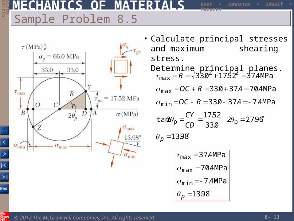
Sample Problem 8.5
• Calculate principal stresses and maximum shearing stress.
Determine principal planes.
98.13
96.2720.33
52.172tan
MPa4.74.370.33
MPa4.704.370.33
MPa4.3752.170.33
pp
min
max
22max
p
CD
CY
ROC
ROC
R
98.13
MPa4.7
MPa4.70
MPa4.37
min
max
max
p