presentation avi
TRANSCRIPT

8/8/2019 Presentation Avi
http://slidepdf.com/reader/full/presentation-avi 1/29
MicrocontrollerMicrocontroller
80518051

8/8/2019 Presentation Avi
http://slidepdf.com/reader/full/presentation-avi 2/29
Contents:Contents:
IntroductionBlock Diagram and Pin Description of the 8051
Registers
Memory mapping in 8051
Stack in the 8051
Timer
Interrupt

8/8/2019 Presentation Avi
http://slidepdf.com/reader/full/presentation-avi 3/29
Why do we need to learnWhy do we need to learnMicroprocessors/controllers?Microprocessors/controllers?
The microprocessor is the core of computer systems.
Nowadays many communication, digitalentertainment, portable devices, arecontrolled by them.
A designer should know what types of
components he needs, ways toreduce production costs and productreliable.

8/8/2019 Presentation Avi
http://slidepdf.com/reader/full/presentation-avi 4/29
Different aspects of aDifferent aspects of amicroprocessor/controllermicroprocessor/controller
Hardware :Interface to the real world
Software :order how to deal with inputs

8/8/2019 Presentation Avi
http://slidepdf.com/reader/full/presentation-avi 5/29
Microprocessor
CPU is stand-alone, RAM,ROM, I/O, timer areseparate
designer can decide on theamount of ROM, RAMand I/O ports.
expansive
versatility general-purpose
Microcontroller
•CPU, RAM, ROM, I/O andtimer are all on a single chip
•fix amount of on-chip ROM,RAM, I/O ports
•for applications in which cost, power and space are critical
•single-purpose
Microprocessor vs. Microcontroller

8/8/2019 Presentation Avi
http://slidepdf.com/reader/full/presentation-avi 6/29
UBC 104 Embedded Systems 6
Microcontroller FamiliesMicrocontroller Families
68H12: Motorola 68H11, 68HC12, …
8051: Intel 8051, 8052, 80251,…
PIC: Microchip PIC16F628, 18F452, 16F877, …
AVR: Atmel ATmega128, ATtiny28L,AT90S8515,…
We a re going to look a t
8 0 5 1 s
8/8/2019 Presentation Avi
http://slidepdf.com/reader/full/presentation-avi 7/29UBC 104 Embedded Systems 7
Tasks for MicrocontrollerTasks for Microcontroller
Controlling of processes (autonomic) e.g. speed of vehicles, chemical processes
Control of devices through humanoperator e.g. remote control, etc

8/8/2019 Presentation Avi
http://slidepdf.com/reader/full/presentation-avi 8/29
Embedded system means the processor is embedded into thatapplication.
An embedded product uses a microprocessor or microcontroller todo one task only.
In an embedded system, there is only one application software thatis typically burned into ROM.
Example: printer, keyboard, video game player
Embedded System

8/8/2019 Presentation Avi
http://slidepdf.com/reader/full/presentation-avi 9/29
1. meeting the computing needs of the task efficiently and costeffectively
• speed, the amount of ROM and RAM, the number of I/O ports and timers, size, packaging, power consumption
• easy to upgrade• cost per unit
2. availability of software development tools
• assemblers, debuggers, C compilers, emulator, simulator,technical support
3. wide availability and reliable sources of the microcontrollers.
Three criteria in Choosing a Microcontroller

8/8/2019 Presentation Avi
http://slidepdf.com/reader/full/presentation-avi 10/29
Block DiagramBlock Diagram
CPU
On-chipRAM
On-chipROM forprogramcode
4 I/O Ports
Timer 0
SerialPortOSC
InterruptControl
External interrupts
Timer 1
Timer/Counter
BusControl
TxD RxDP0 P1 P2 P3
Address/Data
CounterInputs
8/8/2019 Presentation Avi
http://slidepdf.com/reader/full/presentation-avi 11/29
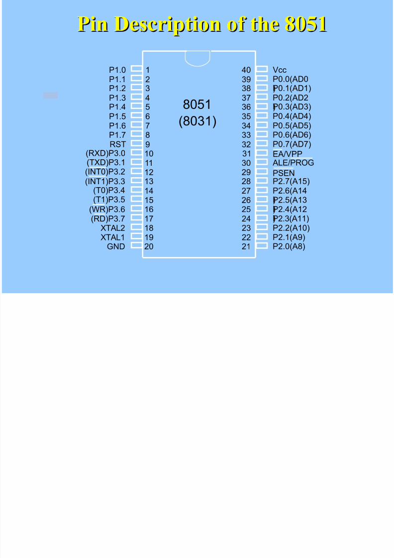
Pin Description of the 8051Pin Description of the 8051
1234567
89101112131415
1617181920
40393837363534
3332313029282726
2524232221
P1.0P1.1P1.2P1.3P1.4P1.5P1.6
P1.7RST(RXD)P3.0(TXD)P3.1
(T0)P3.4(T1)P3.5
XTAL2XTAL1
GND
(INT0)P3.2
(INT1)P3.3
(RD)P3.7(WR)P3.6
VccP0.0(AD0)P0.1(AD1)P0.2(AD2)P0.3(AD3)P0.4(AD4)P0.5(AD5)
P0.6(AD6)P0.7(AD7)
EA/VPPALE/PROG
PSENP2.7(A15)P2.6(A14)P2.5(A13
)P2.4(A12)P2.3(A11)P2.2(A10)P2.1(A9)P2.0(A8)
8051
(8031)

8/8/2019 Presentation Avi
http://slidepdf.com/reader/full/presentation-avi 12/29
Pins of 8051Pins of 8051(( 1/41/4))
Vcc( pin 40):
Vcc provides supply voltage to the chip.
The voltage source is +5V.
GND( pin 20): ground
XTAL1 and XTAL2( pins 19,18)

8/8/2019 Presentation Avi
http://slidepdf.com/reader/full/presentation-avi 13/29
Figure (a). XTAL Connection to 8051Figure (a). XTAL Connection to 8051
C2
30pF
C1
30pF
XTAL2
XTAL1
GND
§Using a quartz crystal oscillator
§We can observe the frequency on the XTAL2 pin.

8/8/2019 Presentation Avi
http://slidepdf.com/reader/full/presentation-avi 14/29
Pins of 8051Pins of 8051(( 2/42/4))
RST( pin 9): reset
It is an input pin and is active high( normally
low) .
The high pulse must be high at least 2 machinecycles.
It is a power-on reset.
Upon applying a high pulse to RST, the
microcontroller will reset and all values inregisters will be lost.
Reset values of some 8051 registers

8/8/2019 Presentation Avi
http://slidepdf.com/reader/full/presentation-avi 15/29
Pins of 8051Pins of 8051(( 3/43/4))
/EA( pin 31): external access
There is no on-chip ROM in 8031 and 8032 .
The /EA pin is connected to GND to indicate the codeis stored externally.
/PSEN & ALE are used for external ROM.
For 8051, /EA pin is connected to Vcc.
“/” means active low.
/PSEN
( pin 29
): program store enable
This is an output pin and is connected to the OE pin of the ROM.

8/8/2019 Presentation Avi
http://slidepdf.com/reader/full/presentation-avi 16/29
Pins of 8051Pins of 8051(( 4/44/4))
ALE( pin 30): address latch enable
It is an output pin and is active high.
8051 port 0 provides both address and data.
The ALE pin is used for de-multiplexing theaddress and data by connecting to the G pin of the 74LS373 latch.
I/O port pins
The four ports P0, P1, P2, and P3.
Each port uses 8 pins.
All I/O pins are bi-directional..

8/8/2019 Presentation Avi
http://slidepdf.com/reader/full/presentation-avi 17/29
Pins of I/O PortPins of I/O Port
The 8051 has four I/O ports Port 0 ( pins 32-39): P0( P0.0~ P0.7) Port 1( pins 1-8) : P1( P1.0~ P1.7) Port 2( pins 21-28): P2( P2.0~ P2.7) Port 3( pins 10-17): P3( P3.0~ P3.7) Each port has 8 pins.
Named P0.X ( X=0,1,...,7) , P1.X, P2.X,P3.X
Ex: P0.0 is the bit 0( LSB) of P0
Ex: P0.7 is the bit 7(MSB) of P0 These 8 bits form a byte.
Each port can be used as input or output (bi-direction).

8/8/2019 Presentation Avi
http://slidepdf.com/reader/full/presentation-avi 18/29
Other PinsOther Pins
P1, P2, and P3 have internal pull-up resisters. P1, P2, and P3 are not open drain.
P0 has no internal pull-up resistors and does notconnects to Vcc inside the 8051. P0 is open drain. Compare the figures of P1.X and P0.X.
However, for a programmer, it is the same to program P0, P1, P2 and P3.
All the ports upon RESET are configured as output.

8/8/2019 Presentation Avi
http://slidepdf.com/reader/full/presentation-avi 19/29
Port 0 with Pull-Up ResistorsPort 0 with Pull-Up Resistors
P0.0P0.1P0.2P0.3P0.4P0.5P0.6P0.7
DS5000
8751
8951
Vcc10 K
P or t 0

8/8/2019 Presentation Avi
http://slidepdf.com/reader/full/presentation-avi 20/29
Registers
A
B
R0
R1
R3
R4
R2
R5
R7
R6
DPH DPL
PC
DPTR
PC
Some 8051 16-bit Register
Some 8-bitt Registers of the 8051

8/8/2019 Presentation Avi
http://slidepdf.com/reader/full/presentation-avi 21/29
Port 3 Alternate FunctionsPort 3 Alternate Functions
1717RDRDP3.7P3.7
1616WR WR P3.6P3.61515T1T1P3.5P3.5
1414T0T0P3.4P3.4
1313INT1INT1P3.3P3.3
1212INT0INT0P3.2P3.2
1111TxDTxDP3.1P3.1
1010RxDRxDP3.0P3.0
PinPinFunctionFunctionP3 BitP3 Bit

8/8/2019 Presentation Avi
http://slidepdf.com/reader/full/presentation-avi 22/29
Memory mapping in 8051Memory mapping in 8051
ROM memory map in 8051 family
0000H
0FFFH
0000H
1FFFH
0000H
7FFFH
8751AT89C51
8752AT89C52
4k
DS5000-32
8k 32k
from Atmel Corporationfrom Dallas Semiconductor

8/8/2019 Presentation Avi
http://slidepdf.com/reader/full/presentation-avi 23/29
RAM memory space allocation in the 8051
7FH
30H
2FH
20H
1FH
17H10H
0FH
07H
08H
18H
00HRegister Bank 0
(Stack) Register Bank 1
Register Bank 2
Register Bank 3
Bit-Addressable RAM
Scratch pad RAM

8/8/2019 Presentation Avi
http://slidepdf.com/reader/full/presentation-avi 24/29
UBC 104 Embedded Systems 24
InterruptsInterrupts
Definition of ‘Interrupt’
Event that disrupts the normalexecution of a program and causes the
execution of special instructions

8/8/2019 Presentation Avi
http://slidepdf.com/reader/full/presentation-avi 25/29
UBC 104 Embedded Systems 25
InterruptsInterrupts
Program
Interrupt Service Routine
Interrupt
Program
time t

8/8/2019 Presentation Avi
http://slidepdf.com/reader/full/presentation-avi 26/29
UBC 104 Embedded Systems 26
Interrupt HandlingInterrupt Handling
Code that deals withinterrupts: InterruptHandler or InterruptService Routines (ISRs)
Address space in codespace
8/8/2019 Presentation Avi
http://slidepdf.com/reader/full/presentation-avi 27/29
UBC 104 Embedded Systems 27
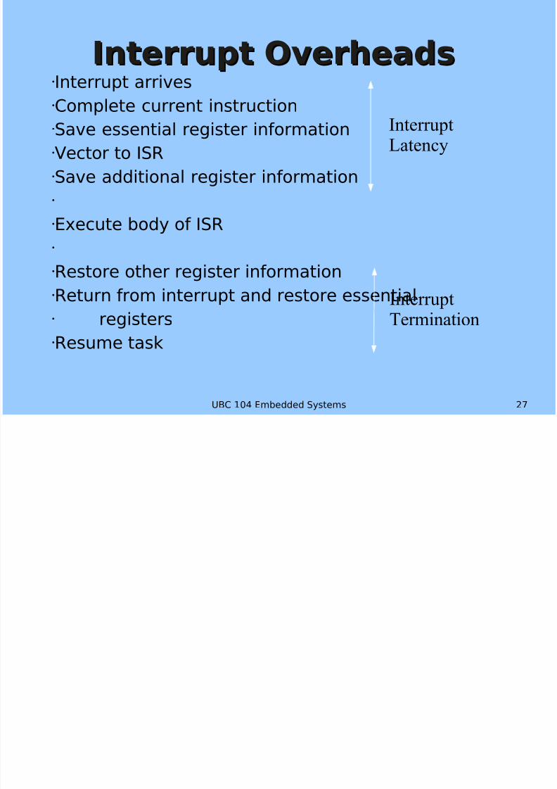
Interrupt OverheadsInterrupt OverheadsInterrupt arrivesComplete current instructionSave essential register informationVector to ISRSave additional register information
Execute body of ISR
Restore other register information
Return from interrupt and restore essential registersResume task
InterruptLatency
InterruptTermination

8/8/2019 Presentation Avi
http://slidepdf.com/reader/full/presentation-avi 28/29
UBC 104 Embedded Systems 28
TimerTimer
A timer is a counter thatis increased withevery time aninstruction isexecuted e.g. 8051with 12MHz
increases a counterevery 1.000 µs
General 8051 has 3timer:
2 16-bit timer 1 16-bit timer
with extra-functionality(introducedwith the 8052)
Timer/Counter Mode Control Register TMOD
Timer/Counter Control Register TCON

8/8/2019 Presentation Avi
http://slidepdf.com/reader/full/presentation-avi 29/29
Summary: InterruptsSummary: Interrupts Definition of ‘Interrupt’:
Event that disrupts the normalexecution of a program and causes the execution of specialinstructions
Handling can beenabled/disabled
Prioritized
Internal or External
External Interrupts:
Level-triggered Edge-triggered
8051: 3 timer interrupts, 2external interrupts & a serialport interrupt
threshold
Level-triggered
Edge-triggered
trigger point
trigger point
t
t