preprint 2006:36 airbag folding based on … 2006:36 airbag folding based on origami mathematics...
TRANSCRIPT

PREPRINT 2006:36
Airbag Folding Based on Origami Mathematics
CHRISTOFFER CROMVIK KENNETH ERIKSSON
Department of Mathematical Sciences Division of Mathematics CHALMERS UNIVERSITY OF TECHNOLOGY GÖTEBORG UNIVERSITY Göteborg Sweden 2006

Preprint 2006:36
Airbag Folding Based on Origami Mathematics
Christoffer Cromvik and Kenneth Eriksson
Department of Mathematical Sciences Division of Mathematics
Chalmers University of Technology and Göteborg University SE-412 96 Göteborg, Sweden
Göteborg, December 2006

Preprint 2006:36 ISSN 1652-9715
Matematiska vetenskaper Göteborg 2006
AIRBAG FOLDING BASED ON ORIGAMI MATHEMATICS
CHRISTOFFER CROMVIK AND KENNETH ERIKSSON
Abstract. A new algorithm for folding three-dimensional airbags is presented. The methodis based on Origami mathematics combined with nonlinear optimization.
The airbag is folded to fit into its compartment. Simulating an inflation therefore requiresan accurate geometric representation of the folded airbag. However, the geometry is oftenspecified in the inflated three-dimensional form, and finding a computer model of the foldedairbag is a non-trivial task. The quality of a model is usually measured by the difference inarea between the folded and the inflated airbags.
The method presented here starts by approximating the geometry of the inflated airbag bya quasi-cylindrical polyhedron. Origami mathematics is used to compute a crease pattern forfolding the polyhedron flat. The crease pattern is computed with the intention of being fairlysimple and to resemble the actual creases on the real airbag.
The computation of the crease pattern is followed by a computation of the folding. Thisis based on solving an optimization problem in which the optimum is a flat folded model.Finally, the flat airbag is further folded or rolled into its final shape (without using Origami).
The method has been successfully applied to various models of passenger airbags, providingmore realistic geometric data for airbag inflation simulations.
1. Introduction
Simulating a crash when the crash test dummy hits the airbag while it is still expandingremains a challenge to the industry. This situation is called out-of-position (OOP), reflectingthat the airbag was not designed for occupants that are sitting too close or for some other reasonhit the airbag before it is fully inflated.
The difficulty with an OOP situation compared to an in-position situation is that the inflationof the folded airbag is much more important. It has to be realistically computed, since it affectsthe impact of the dummy. Attaining a realistic simulation means starting with a correct geometryof the folded airbag and simulating the inflation with correct gas dynamics. Several commercialsoftware packages exist that can simulate the inflation process of an airbag, e.g., the explicitFinite Element (FE) code LS-DYNA [5].
This work aims at developing an algorithm for computing an accurate geometry of the flatfolded airbag. Different airbags are folded by different methods and with different numbers andtypes of foldings. The airbags are often folded by both machines and humans according to afolding scheme. Still, the creases are not entirely deterministically positioned. It is very difficultto control the placement of smaller creases. The folding schemes all assume that the airbag liesflat and stretched in some direction. In this position, different foldings are executed until thedimension of the folded airbag is small enough so that it fits into the airbag compartment. Thefoldings can be a combination of simple folds, but also roll folds.
Some preprocessors to LS-DYNA, e.g., EASi-FOLDER [4] and OASYS-PRIMER [1] contain softwarefor folding a (nearly) flat FE airbag mesh. They are capable of executing the type of foldingsthat are normally used in production on flat airbags, e.g., roll-fold, z-fold. However, they are notas accurate when folding an airbag in its three dimensional shape to a flat airbag.
Some airbag models have a simple construction, e.g., the driver model which is made of twocircular layers sewn together. It is essentially two-dimensional. Passenger airbags are often more
1
2 CHRISTOFFER CROMVIK AND KENNETH ERIKSSON
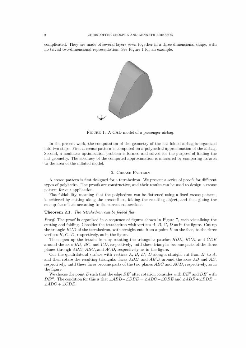
complicated. They are made of several layers sewn together in a three dimensional shape, withno trivial two-dimensional representation. See Figure 1 for an example.
Figure 1. A CAD model of a passenger airbag.
In the present work, the computation of the geometry of the flat folded airbag is organizedinto two steps. First a crease pattern is computed on a polyhedral approximation of the airbag.Second, a nonlinear optimization problem is formed and solved for the purpose of finding theflat geometry. The accuracy of the computed approximation is measured by comparing its areato the area of the inflated model.
2. Crease Pattern
A crease pattern is first designed for a tetrahedron. We present a series of proofs for differenttypes of polyhedra. The proofs are constructive, and their results can be used to design a creasepattern for our application.
Flat foldability, meaning that the polyhedron can be flattened using a fixed crease pattern,is achieved by cutting along the crease lines, folding the resulting object, and then gluing thecut-up faces back according to the correct connections.
Theorem 2.1. The tetrahedron can be folded flat.
Proof. The proof is organized in a sequence of figures shown in Figure 7, each visualizing thecutting and folding. Consider the tetrahedron with vertices A, B, C, D as in the figure. Cut upthe triangle BCD of the tetrahedron, with straight cuts from a point E on the face, to the threevertices B, C, D, respectively, as in the figure.
Then open up the tetrahedron by rotating the triangular patches BDE, BCE, and CDEaround the axes BD, BC, and CD, respectively, until these triangles become parts of the threeplanes through ABD, ABC, and ACD, respectively, as in the figure.
Cut the quadrilateral surface with vertices A, B, E′, D along a straight cut from E′ to A,and then rotate the resulting triangular faces ABE′ and AE′D around the axes AB and AD,respectively, until these faces become parts of the two planes ABC and ACD, respectively, as inthe figure.
We choose the point E such that the edge BE′ after rotation coinsides with BE′′ and DE′ withDE′′′. The condition for this is that ∠ABD+∠DBE = ∠ABC+∠CBE and ∠ADB+∠BDE =∠ADC + ∠CDE.
AIRBAG FOLDING BASED ON ORIGAMI MATHEMATICSTHIS WORK WAS FUNDED BY AUTOLIV DEVELOPMENT AB.3
Using this, we may now (partly) restore the surface of the tetrahedron by joining the surfacesABE′′ and ABE′′C along the edge BE′′, and the surfaces ADE′′′ and ADE′′′C along the edgeDE′′′.
Finally we rotate the (partly double layered) surface ADE′′′C around the axis AC until itcoincides with the plane through A,B and C as in the figure. To conclude the proof of the flatfoldability of the tetrahedron we now note that the point E′′′ after rotation coincides with E′′.We may therefore now completely restore the topology of the original tetrahedron by joining theedges AE′′ and AE′′′ (after rotation) and the edges CE′′ and CE′′′ (after rotation). ¤
Note that the proof is based on cutting and gluing. It does not reveal if there is a continuousdeformation to a flat shape.
Remark 2.1. Concerning the line AE′ we remark that the angles ∠BAE′ and ∠DAE′ satisfy∠BAE′ + ∠DAE′ = ∠BAD and ∠BAC − ∠BAE′ = ∠CAD − ∠DAE′, as in the figure, andare thus independent of the plane BCD. We further note that we may also consider rotatingthe triangles BDE, BCE and CDE in the opposite direction, again until they become parts ofthe planes ABD, ABC and ACD, respectively, as in figure. We now choose the point E so that∠ABD−∠DBE = ∠ABC−∠CBE and ∠ADB−∠BDE = ∠ADC−∠CDE. Continuing fromthe figure we may then again make a straight cut from E′ to A (partly double layered). Again,when we now rotate around the axes AB and AD as before the (rotated) point E′ will coincidewith E′′ and E′′′ respectively, and we can partly restore the tetrahedron by joining along theedges. Finally, after rotation around AC we may completely restore the topology of the surfaceof the tetrahedron by joining along the edges. Concerning the crease line from A to E′′ we notethat again the angles ∠BAE′ and ∠DAE′ must satisfy the same equations ∠BAE′ + ∠DAE′ =∠BAD and ∠BAC − ∠BAE′ = ∠CAD − ∠DAE′ as before and therefore must be the same asabove. We therefore conclude that this crease line is independent of both direction of rotation ofthe triangles BCE, BDE and CDE, and of the position and orientation of the plane BCD (aslong as the angles at A are unchanged).
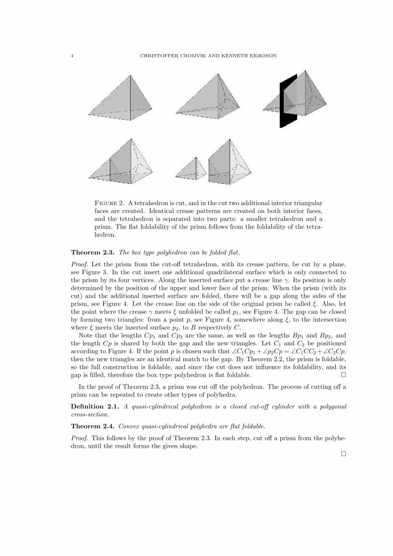
We now proceed by cutting the tetrahedron by a plane, see Figure 2. We call the cut-offtetrahedron a prism type polyhedron.
Theorem 2.2. The prism type polyhedron can be folded flat.
Proof. Consider a tetrahedron ABCD with the crease pattern from the proof of Theorem 2.1.Cut the tetrahedron with a plane, see Figure 2. In the cut, insert two additional triangularsurfaces, such that the two cutoff parts are closed, but not separated. The “smaller” cutoff partis a tetrahedron, and the “bigger” part is a prism type polyhedron. Let the vertices of the smallertetrahedron be a, b, c, d, where A = a, b lies on the edge AB, c on AC and d on AD.
Remark 2.1 shows that the crease line from A to E′, see Figure 7, is independent of howthe inserted triangular face of the “smaller” tetrahedron is folded. Let it be folded to theinterior of the “smaller” tetrahedron. This means that a crease pattern can be constructedwhich will coincide with the crease pattern of the original tetrahedron, i.e., the crease line whichis constructed by drawing a straight line from a to e′ will coincide with the crease line that wascreated from the line segment from A to E′ in the proof of Theorem 2.1.
Now, make an identical copy of the crease pattern on the inserted triangular face belonging tothe prism. Folding the original tetrahedron with its inserted triangular faces is possible by theconstruction of the crease pattern. Let the two polyhedra be separated by moving the tetrahedronin the plane. By the foldability of the tetrahedron, both the smaller tetrahedron and the prismcan be folded flat. ¤
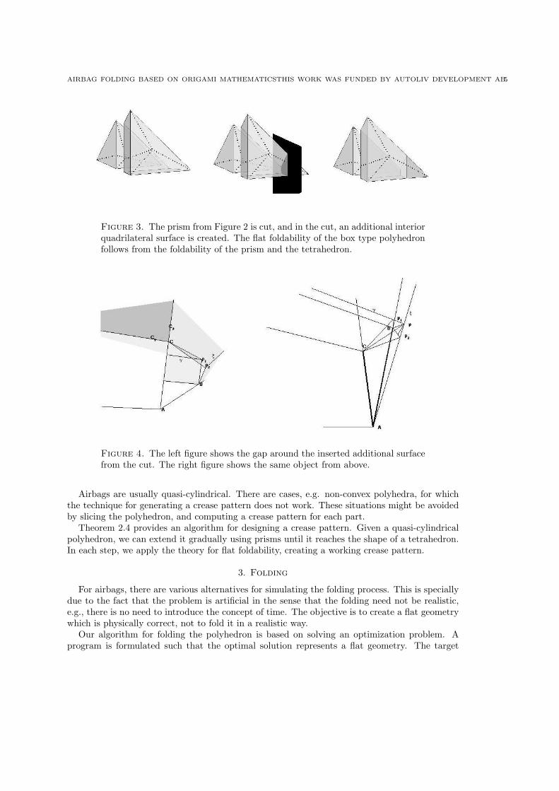
Next, we cut the prism type polyhedron by a plane, see Figure 3. We call the cut-off prism abox type polyhedron.
4 CHRISTOFFER CROMVIK AND KENNETH ERIKSSON
Figure 2. A tetrahedron is cut, and in the cut two additional interior triangularfaces are created. Identical crease patterns are created on both interior faces,and the tetrahedron is separated into two parts: a smaller tetrahedron and aprism. The flat foldability of the prism follows from the foldability of the tetra-hedron.
Theorem 2.3. The box type polyhedron can be folded flat.
Proof. Let the prism from the cut-off tetrahedron, with its crease pattern, be cut by a plane,see Figure 3. In the cut insert one additional quadrilateral surface which is only connected tothe prism by its four vertices. Along the inserted surface put a crease line γ. Its position is onlydetermined by the position of the upper and lower face of the prism. When the prism (with itscut) and the additional inserted surface are folded, there will be a gap along the sides of theprism, see Figure 4. Let the crease line on the side of the original prism be called ξ. Also, letthe point where the crease γ meets ξ unfolded be called p1, see Figure 4. The gap can be closedby forming two triangles: from a point p, see Figure 4, somewhere along ξ, to the intersectionwhere ξ meets the inserted surface p2, to B respectively C.
Note that the lengths Cp1 and Cp2 are the same, as well as the lengths Bp1 and Bp2, andthe length Cp is shared by both the gap and the new triangles. Let C1 and C2 be positionedaccording to Figure 4. If the point p is chosen such that ∠C1Cp1 +∠p2Cp = ∠C1CC2 +∠C2Cp,then the new triangles are an identical match to the gap. By Theorem 2.2, the prism is foldable,so the full construction is foldable, and since the cut does not influence its foldability, and itsgap is filled, therefore the box type polyhedron is flat foldable. ¤
In the proof of Theorem 2.3, a prism was cut off the polyhedron. The process of cutting off aprism can be repeated to create other types of polyhedra.
Definition 2.1. A quasi-cylindrical polyhedron is a closed cut-off cylinder with a polygonalcross-section.
Theorem 2.4. Convex quasi-cylindrical polyhedra are flat foldable.
Proof. This follows by the proof of Theorem 2.3. In each step, cut off a prism from the polyhe-dron, until the result forms the given shape.
¤
AIRBAG FOLDING BASED ON ORIGAMI MATHEMATICSTHIS WORK WAS FUNDED BY AUTOLIV DEVELOPMENT AB.5
Figure 3. The prism from Figure 2 is cut, and in the cut, an additional interiorquadrilateral surface is created. The flat foldability of the box type polyhedronfollows from the foldability of the prism and the tetrahedron.
Figure 4. The left figure shows the gap around the inserted additional surfacefrom the cut. The right figure shows the same object from above.
Airbags are usually quasi-cylindrical. There are cases, e.g. non-convex polyhedra, for whichthe technique for generating a crease pattern does not work. These situations might be avoidedby slicing the polyhedron, and computing a crease pattern for each part.
Theorem 2.4 provides an algorithm for designing a crease pattern. Given a quasi-cylindricalpolyhedron, we can extend it gradually using prisms until it reaches the shape of a tetrahedron.In each step, we apply the theory for flat foldability, creating a working crease pattern.
3. Folding
For airbags, there are various alternatives for simulating the folding process. This is speciallydue to the fact that the problem is artificial in the sense that the folding need not be realistic,e.g., there is no need to introduce the concept of time. The objective is to create a flat geometrywhich is physically correct, not to fold it in a realistic way.
Our algorithm for folding the polyhedron is based on solving an optimization problem. Aprogram is formulated such that the optimal solution represents a flat geometry. The target
6 CHRISTOFFER CROMVIK AND KENNETH ERIKSSON
function, to be minimized, is a sum of rotational spring potentials, one spring over each crease.The minimal value of a spring potential is found when a fold is completed. The constraintsare formulated in order to conserve a physically correct representation of the polyhedron, whichmeans conserving the area and avoiding any self-intersections of the faces of the polyhedron.
The crease pattern over a polyhedron induces a subdivision of polygons called patches. Inaddition, the patches are triangulated, and the interior of the polyhedron is meshed with tetra-hedra. Let the nodes of the mesh be {xi}n
i=1, and let the indices of the surface nodes be IS .Let the tetrahedra be {Ki}nK
i=1 and set IK = {1, . . . , nK}. Let the four indices of the nodes oftetrahedron k be Vk(i), i = 1, . . . , 4. The edges of the triangular faces are denoted {Ei}nE
i=1, andthe indices of the two nodes of edge e are We(i), i = 1, 2.
Denote the creases {Ci}nCi=1. The spring potential over each crease Ci is computed using
the scalar product of the normals, n1i ,n
2i , of the two neighbouring patches. The normals point
outward from the polyhedron, and the scalar product is 1 when the two patches are parallel, and−1 when the fold is completed.
The folding process of a polyhedron with n nodes (surface and interior mesh nodes) is formu-lated as the following nonlinear program with f : R3n → R,
minx
f(x)
f(x) = f1(x) + f2(x) + f3(x)
= km
nK∑
k=1
4∑
i=1
4∑
j=i+1
‖xVk(i) − xVk(j)‖ − dVk(i),Vk(j)
2
+nC∑
i=1
n1i · n2
i + kp
nE∑
i=1
(‖xWi(1) − xWi(2)‖ − lWi
)2
,
subject to
vol(Ki) ≥ ε1, i = 1, . . . , nK ,
dist(xi,Kj) ≥ ε2, i ∈ IS , j ∈ IK \ pi,
where dij is the original distance between node xi and xj , li is the original length of edge iand km, kp are penalty parameters. The first constraint function is vol(Ki) which is the signedvolume of the tetrahedron Ki. The second constraint is dist(xi,Kj), which is the distance froma surface node xi to a tetrahedron Kj , and pi are the tetrahedron indices connected to node xi.Finally, ε1 and ε2 are small positive constants.
The target function f is composed of three parts. f1 is a penalty function which strives tokeep the tetrahedral mesh uniform. f2 is the virtual spring potential which drives the folding.f3 is a penalty function which keeps the edges of the triangles stiff. This is used to maintain theshape and surface area of the patches.
4. Numerical Example
In section 2, a theory for computing a crease pattern was discussed. To demonstrate itspractical use, and also to demonstrate the folding algorithm, a numerical experiment is presented.From a CAD-drawing, an airbag shaped polyhedron was constructed. The surface area of theapproximation differs about 0.5% to the original area. An in-house optimization solver was usedto solve the optimization problem in section 3. It is a Fortran 90 implementation of a low-storageQuasi-Newton SQP method [6, 3, 2], that can handle a few thousand variables and constraints.
AIRBAG FOLDING BASED ON ORIGAMI MATHEMATICSTHIS WORK WAS FUNDED BY AUTOLIV DEVELOPMENT AB.7
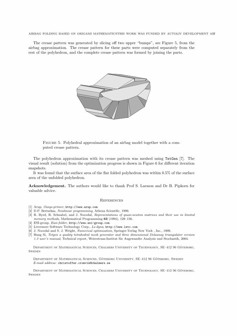
The crease pattern was generated by slicing off two upper “bumps”, see Figure 5, from theairbag approximation. The crease pattern for these parts were computed separately from therest of the polyhedron, and the complete crease pattern was formed by joining the parts.
Figure 5. Polyhedral approximation of an airbag model together with a com-puted crease pattern.
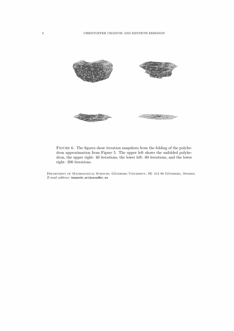
The polyhedron approximation with its crease pattern was meshed using TetGen [7]. Thevisual result (solution) from the optimization progress is shown in Figure 6 for different iterationsnapshots.
It was found that the surface area of the flat folded polyhedron was within 0.5% of the surfacearea of the unfolded polyhedron.
Acknowledgement. The authors would like to thank Prof S. Larsson and Dr B. Pipkorn forvaluable advice.
References
[1] Arup, Oasys-primer, http://www.arup.com.[2] D.P. Bertsekas, Nonlinear programming, Athena Scientific, 1999.[3] R. Byrd, R. Schnabel, and J. Nocedal, Representations of quasi-newton matrices and their use in limited
memory methods, Mathematical Programming 63 (1994), 129–156.[4] ESI-group, Easi-folder, http://www.esi-group.com.[5] Livermore Software Technology Corp., Ls-dyna, http://www.lstc.com.[6] J. Nocedal and S. J. Wright, Numerical optimization, Springer-Verlag New York , Inc., 1999.[7] Hang Si, Tetgen a quality tetrahedral mesh generator and three dimensional Delaunay triangulator version
1.3 user’s manual, Technical report, Weierstrass-Institut fur Angewandte Analysis und Stochastik, 2004.
Department of Mathematical Sciences, Chalmers University of Technology, SE–412 96 Goteborg,Sweden
Department of Mathematical Sciences, Goteborg University, SE–412 96 Goteborg, SwedenE-mail address: [email protected]
Department of Mathematical Sciences, Chalmers University of Technology, SE–412 96 Goteborg,Sweden
8 CHRISTOFFER CROMVIK AND KENNETH ERIKSSON
Figure 6. The figures show iteration snapshots from the folding of the polyhe-dron approximation from Figure 5. The upper left shows the unfolded polyhe-dron, the upper right: 40 iterations, the lower left: 60 iterations, and the lowerright: 200 iterations.
Department of Mathematical Sciences, Goteborg University, SE–412 96 Goteborg, SwedenE-mail address: [email protected]

AIRBAG FOLDING BASED ON ORIGAMI MATHEMATICSTHIS WORK WAS FUNDED BY AUTOLIV DEVELOPMENT AB.9
Figure 7. Supporting figure for the proof of Theorem 2.1. The proof followsthe figures from left to right beginning at the top.