preparation and characterization of carbon paste micro-electrode based on carbon nano-particles
TRANSCRIPT

A
niaCbmh©
K
1
bepcFamim([fietaa
0d
Available online at www.sciencedirect.com
Talanta 74 (2007) 405–411
Preparation and characterization of carbon paste micro-electrodebased on carbon nano-particles
Samo B. Hocevar ∗, Bozidar OgorevcAnalytical Chemistry Laboratory, National Institute of Chemistry, Hajdrihova 19, SI-1000 Ljubljana, Slovenia
Received 2 August 2007; received in revised form 24 September 2007; accepted 1 October 2007Available online 7 October 2007
bstract
The present paper demonstrates the preparation and characterization of micro-electrodes based on carbon paste which is composed of carbonano-particles with an average diameter of 30 nm and binding oil. The carbon paste electrode material is encased in pulled glass capillaries rangingn diameter from several tens down to less than ten micro-meters (r = 4.5 �m). Manipulation of the carbon paste micro-electrode (CPME) wasccomplished via newly developed piston-driven system which construction and related problems are presented. Several parameters influencing thePME performance including carbon paste composition and its electrochemical activation/preconditioning were investigated. Basic electrochemical
ehavior and properties were examined using typical redox system, i.e. potassium hexacyanoferrate. Applicability of the proposed carbon pasteicro-electrode is illustrated by measuring some potentially interesting organic and inorganic analytes such as dopamine, ascorbic acid and selectedeavy metals.2007 Elsevier B.V. All rights reserved.
ing ch
dftpeimnteipn
ia
eywords: Carbon paste micro-electrode; Nano-particles; Voltammetry; Stripp
. Introduction
Since their first introduction in 1958 by Adams [1], car-on paste electrodes have been extensively employed in variouslectrochemical detection schemes due to their simple and fastreparation, facile surface renewing, biocompatibility, non-toxicharacter, and relatively low-background characteristics [2].urthermore, carbon paste-based electrode material is extremelyttractive for its subsequent bulk modification with differentodifiers, e.g. electrocatalysts and/or enzymes by simply mix-
ng them into the carbon paste matrix [3–6]. In addition, surfaceodification of carbon paste electrodes with thin metal films [7],
bio)recognition elements [8,9] and/or protective membranes6,10,11] is also widely applicable, although their bulk modi-cation is more convenient and common. Mostly, carbon pastelectrodes are used as conventional size electrodes in combina-
ion with different holders which facilitate their manipulationnd renewing of the electrode surface. There are several reportsbout their miniaturization, where the carbon paste was intro-∗ Corresponding author. Tel.: +386 1 4760 214; fax: +386 1 4760 300.E-mail address: [email protected] (S.B. Hocevar).
vacdmsi
039-9140/$ – see front matter © 2007 Elsevier B.V. All rights reserved.oi:10.1016/j.talanta.2007.10.007
ronopotentiometry; Dopamine; Ascorbate; Lead; Cadmium
uced into small glass or Teflon capillaries with diametersrom 75 to 100 �m [6,12–14]. To the best of our knowledge,here is only one work reporting the preparation of carbonaste micro-electrode with its radius of 10 �m [15]. One of themerging problems accompanying miniaturization proceduress the size of carbon particles employed in the carbon paste and
anipulation of the carbon paste micro-electrode. Conductiveano-materials and in particular carbon nano-tubes along withheir attractive mechanical, electronic and electrocatalytic prop-rties offer numerous possibilities for introducing new schemesn electrochemical sensor (micro)design, among which, carbonaste electrodes and micro-electrodes certainly represent a sig-ificant part [16–19].
Micro- and ultra-micro electrodes have become of increas-ng importance in electroanalysis, particularly in biomedicalnd environmental analysis, not only because they offer con-enient measurements in extremely small sample volumes andt micro-locations, but also due to their inherently advantageousharacteristics [20,21], such as prevailing radial diffusion, thin
ouble layer, low capacitive currents and low Ohmic drop, fastass flux and high current densities, significantly enhancedignal to noise ratio, high temporal and spatial resolution,mmunity to convection, ready measurements in highly resistive
4 / Tal
mrspefotegodst
(aiowaefis
2
2
puUEteatMo(
2
dsA(AgstBpa
taao
2m
b2B(mdApceto
2
Cyclic voltammetric measurements for the characterizationof CPMEs were performed in the solution containing 0.1 Mpotassium chloride together with 1 mM potassium hexacyano-
06 S.B. Hocevar, B. Ogorevc
edia, enabled two electrode configuration, and neverthelesselatively low-cost [22,23]. Thus, combining miniaturizationtrategies with such a flexible electrode material as carbonaste [2] together with advantageous electronic, physical andlectrochemical features of carbon nano-particles [24] is there-ore very promising, in particular considering developmentf sensitive electrochemical micro-sensors and biosensors forheir potential application in more challenging environments,.g. in vivo and in vitro molecular physiological studies, sin-le cell secretion monitoring, measurements in the absencef a supporting electrolyte, etc. However, progress in thisirection has been mainly restrained by the availability of low-ize carbon particles and/or the degree of micro-fabricationechnology.
In this work we report on the usage of carbon nano-particlesCarbon Black) as an attractive electrode nano-material whichlso enables the circumvention of size-related problems dur-ng tailoring carbon paste micro-electrodes. The constructionf a simple piston-driven micro-manipulator is also presentedhich serves as a holder for the carbon paste micro-electrode
nd, at the same time, for simple manipulation/renewal of thelectrode surface. The electrochemical characterization and per-ormance of the above-mentioned micro-electrode is presentedn the model solution containing dopamine, ascorbate and someelected heavy metals.
. Experimental
.1. Apparatus
Cyclic voltammetric, square-wave voltammetric and strip-ing chronopotentiometric measurements were carried outsing a modular electrochemical system Autolab (Eco Chemie,trecht, The Netherlands) equipped with PGSTAT12 andCD modules driven by GPES software (Eco Chemie). A
hree-electrode configuration consisted of a carbon paste micro-lectrode (CPME), Ag/AgCl/KCl(satd.), and a platinum wires the working, reference and counter electrode, respec-ively. Electrochemical experiments were carried out in a
etrohm-type voltammetric cell (10–20 ml), placed in a lab-ratory made Faraday cage, at conditioned room temperature23 ± 1 ◦C).
.2. Reagents
Potassium hexacyanoferrate (HCF) was provided by Fluka,opamine by Sigma and ascorbic acid by Kemika. Bismuth(III)tock solution (1000 mg L−1 in 5 wt.% HNO3) was supplied byldrich, while both lead(II) and cadmium(II) stock solutions
1000 mg L−1 in 5 wt.% HNO3) were purchased from Merck.ll other chemicals employed in this work were of analyticalrade purity and used as received. Water used to prepare allolutions throughout the work was first deionized and then fur-
her purified via an Elix 10/Milli-Q Gradient unit (Millipore,edford, USA). Acetate buffer solution (0.05 M, pH 4.5) wasrepared by mixing appropriate amounts of acetic acid (Merck)nd sodium acetate (Merck). A 0.1 M phosphate buffer solu-Fdmo
anta 74 (2007) 405–411
ion was prepared by mixing corresponding amounts of 0.1 Mqueous solutions of disodium hydrogen phosphate (Merck)nd sodium dihydrogen phosphate (Kemika) to obtain the pHf 7.4.
.3. Preparation of carbon paste electrode andicro-electrode
If not otherwise specified, the carbon paste was preparedy thoroughly homogenizing an adequate amount of usually0% of extremely conductive carbon nano-particles (Carbonlack, Printex XE 2, Degussa, Germany) and paraffin liquid
Uvasol, Merck) using a pestle and mortar. Finally, the pasteixture was packed into the pulled glass capillary with radius
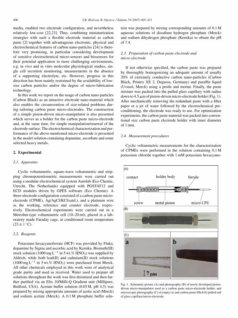
own to 4.5 �m of piston-driven micro-electrode holder (Fig. 1).fter mechanically removing the redundant paste with a filteraper or a jet of water followed by the electrochemical pre-onditioning, the electrode was ready to use. For optimizationxperiments, the carbon paste material was packed into conven-ional size carbon paste electrode holder with inner diameterf 1 mm.
.4. Measurement procedures
ig. 1. Schematic picture (A) and photography (B) of newly developed piston-riven micro-manipulator used as a carbon paste micro-electrode holder, andicroscopic photography (C) of empty (a) and carbon paste filled (b) pulled end
f glass capillary/micro-electrode.

/ Talanta 74 (2007) 405–411 407
ftswp
dtuD1acnt
3
ptcaiiiaaatpspadcaaotiCceflc(
ptwee2hab
Fig. 2. Effect of Carbon Black loading (%) in carbon paste upon the peak current(A) and peak separation (B) at carbon paste electrode with radius of 0.5 mm in thesrf
ptpmc1bHtoi+csincctess
S.B. Hocevar, B. Ogorevc
errate as a typical redox system by scanning potential inhe range from +0.5 to 0.0 V. Other cyclic voltammetric andquare-wave voltammetric measurements of organic analytesere carried out in a 0.1 M phosphate buffer solution withH 7.4.
Stripping chronopotentiometric measurements were con-ucted in a 0.05 M acetate buffer solution with pH of 4.5 inhe presence of dissolved oxygen. The deposition potential ofsually −1.2 V was applied to the working electrode for 120 s.uring the deposition period the solution was stirred, and after5 s of equilibration, a chronopotentiogram was recorded bypplying the oxidative current of 0.05 �A between working andounter electrode. The scan was terminated at +0.15 V. Prior toext measurement, the working electrode was held for 30 s athe potential of +0.3 V in a stirred solution.
. Results and discussion
Preliminary experiments have proven that handling a carbonaste micro-electrode (CPME) can be extremely tedious androublesome without an appropriate holder, which would offeronvenient manipulation and renewal of the electrode surfacend would at the same time serve as electrode housing. Hav-ng this in mind, we developed a new electrode holder, whichs based on a piston-driven micro-manipulator system presentedn schematic Fig. 1A and as photography in Fig. 1B. The wholerrangement is constructed from parts which are usually used asccessories in flow-system techniques, such as ferrules, unionsnd end plugs. The holder body (Fig. 1A) consists of two fit-ings (unions) with a ferrule on one side and a plastic screw (endlug) with embedded copper wire on the other side. The ferruleerves as a holder for glass capillary which is filled with carbonaste, while the screw on the other side of the body serves asmanipulator for copper wire. The copper wire, with the sameiameter as the inner diameter of the non-pulled part of glassapillary, provides renewal of the electrode surface by pushingcarbon paste toward capillary’s pulled end and at the same timessures an electric contact with the instrument. The pulled endf glass capillary (Fig. 1C), which is prepared by fine pullingechnique using a capillary puller followed by precise polish-ng using micro-electrode beveller, also defines the size of thePME. When a portion of carbon paste is pushed through theapillary with aim at renewing the electrode surface, the pullednd of glass capillary is gently brushed with a filter paper orushed with a jet of water from plastic squeeze bottle. The glassapillary is filled with a carbon paste material through its widernon-pulled) end.
Another problem emerged during preparation of the carbonaste micro-electrode is associated with the size of elec-rode material, i.e. carbon particles, which are mixed togetherith selected binding oil forming an appropriate carbon paste
lectrode material. To circumvent this size-limiting issue, wemployed carbon nano-particles (Carbon Black, Printex XE
, Degussa, Germany) with average diameter of 30 nm whichave been proven as a very suitable, extremely conductivend relatively inexpensive electrode material. To provide theest possible operation of the CPME, we optimized severalsiio
olution of 1 mM HCF containing 0.1 M KCl. Cyclic voltammetry with a scanate of 100 mV s−1, initial potential, 0.5 V; final potential, 0.0 V. Preconditioningor 1 s at +1.4 V.
arameters, such as composition of carbon paste material, elec-rochemical preconditioning of electrode surface, etc. In thisreliminary part, aimed at shortening and simplifying the opti-ization step, we carried out the experiments employing a
onventional size carbon paste electrode with a diameter ofmm. Fig. 2 demonstrates the effect of carbon particles-to-inding oil ratio upon the cyclic voltammetric signal for 1 mMCF as a typical redox system for common testing of new elec-
rode materials. Before testing the electrochemical performancef carbon paste material, the electrode was preconditionedn the solution of 0.1 M KCl using a constant potential of1.4 V for 1 s. Experiments which are related to this electro-hemical preconditioning step are discussed below. As can beeen from Fig. 2A, the highest cathodic current signal/peaks obtained at the electrode surface containing 20% of carbonano-particles and 80% of binding oil. Lower current in thease of even higher amount of carbon nano-particles, i.e. 25%,an be ascribed to lower consistency of the carbon paste athis ratio also observed as crushing during its preparation. Wexamined the effect of carbon paste composition upon the peakeparation between anodic and cathodic current peaks corre-ponding to HCF redox system shown in Fig. 2B. The peak
eparation characteristics indicating the electron transfer kinet-cs (i.e. the degree of reversibility) are of great significancen determining the electrochemical detection capabilities. Webserved that, also in accordance with experiments described
4 / Tal
ilbbrm
iptefntoHdaitiod+pt
Fui
1tpohcetmdoboButmtsciw
08 S.B. Hocevar, B. Ogorevc
n Fig. 2A, the highest electrochemical performance, i.e. theowest peak separation, was achieved when the ratios of car-on particles-to-binding oil were 25:75 and 20:80. On theasis of this study and results from Fig. 2A, the correspondingatio of 20:80 was selected and used in the following experi-ents.As already mentioned above, we noticed considerable
mprovement in electrochemical signal, if the surface of carbonaste was subjected to electrochemical preconditioning prioro its use. Hence, we examined the parameters, which mightxhibit the pronounced effect upon the electroanalytical per-ormance of carbon paste electrode based on Carbon Blackano-particles, i.e. preconditioning potential, preconditioningime and the composition of preconditioning solution. The effectf preconditioning potential upon the signal height for 1 mMCF is demonstrated in Fig. 3A. A stepwise increase of precon-itioning potential in the range from 0.0 to +0.8 V did not elicitny significant improvement with respect to the electrochem-cal behavior of CPME. However, after sequential increasinghe potential from +0.8 to +1.6 V, we observed a substantialmprovement of the signal corresponding to the reduction andxidation of HCF. Since the preconditioning at +1.6 V yielded
istinctly distorted signals, we corroborated the potential of1.4 V as an optimum. Furthermore, we studied the influence ofreconditioning time upon the signal height and we concludedhat the most adequate preconditioning time is in the range fromig. 3. Effect of preconditioning potential (A) and preconditioning time (B)pon the peak current obtained at carbon paste electrode with radius of 0.5 mmn the solution of 1 mM HCF containing 0.1 M KCl. Other conditions as in Fig. 2.
yaHettscepascs
F0f0a
anta 74 (2007) 405–411
to 3 s as depicted in Fig. 3B. With longer preconditioningimes, the electrode response commenced to decrease and afterrolonged preconditioning the distorted voltammograms werebserved. Since the preconditioning is carried out at relativelyigh potential of +1.4 V, we can assume that prolonged exposurean induce additional over-oxidation of the binding oil and/orlectrode surface reflecting attenuated conductivity of the elec-rode and in addition, longer exposure to the aforesaid potential
ight induce oxygen evolution which partially covers and thusecreases the active electrode surface. However, the applicationf higher potential (+1.4 V) is necessary (Fig. 3A) as the car-on paste material includes relatively high amount of bindingil and due to the inherent surface characteristics of Carbonlack material. Another parameter with a pronounced effectpon the electrochemical performance is the medium in whichhe preconditioning takes place. To further improve the perfor-
ance of newly developed carbon paste electrode, we checkedhe impact of different electrolytes added to the preconditioningolution, i.e. NaNO3, LiClO4, KCl and H2SO4 on the resultingurrent signal. Corresponding cyclic voltammograms recordedn test solution containing 1 mM HCF are presented in Fig. 4,hich clearly demonstrates that the most suitable electrolyteielding the highest current signal and the lowest peak sep-ration of 60 mV between reduction and oxidation peaks forCF is KCl (thick line). Thus, we used KCl in all subsequent
xperiments as the most favorable electrolyte for the precondi-ioning step. The two most important processes involved duringhe preconditioning step are (i) oxidation of the Carbon Blackurface, i.e. its electrochemical modification with carbonyl andarboxyl groups and (ii) partial oxidation of binder oil tonhance electrical cross-communication between carbon nano-articles. The proper selection of the electrolyte has evidently
profound effect upon the preconditioning of the electrodeurface. Its role might be associated with different interfacialatalytic reactions between electrolyte ions and the electrodeurface.
ig. 4. Cyclic voltammograms obtained at carbon paste electrode with radius of.5 mm in the solution of 1 mM HCF containing 0.1 M KCl after preconditioningor 3 s at +1.4 V in the solution of 0.1 M KCl (thick line), 0.1 M H2SO4 (thin line),.1 M LiClO4 (dotted line) and 0.1 M NaNO3 (dashed line). Other conditionss in Fig. 2.

/ Talanta 74 (2007) 405–411 409
dmcs0pite
I
wdecHEmf6tctp
Fig. 5. Cyclic voltammograms obtained at carbon paste micro-electrodes withradius of 4.5 �m (a), 14 �m (b), 22 �m (c) and 62 �m (d) in the solution of 1 mMHpv
i
F(Bws
S.B. Hocevar, B. Ogorevc
The following experiments were performed using our newlyesigned piston-driven system in combination with carbon pasteicro-electrodes. To get more insights into the electrochemi-
al characteristics of the aforementioned micro-electrodes wetudied their response in the solution containing 1 mM HCF and.1 KCl with respect to their radius (Fig. 5). In addition, we com-ared the experimental results with theoretical values, as shownn the inset of Fig. 5, that were calculated using a corrected equa-ion for limiting currents corresponding to disk micro-electrodesmbedded in a thin insulation layer [21,25]:
L =(
1 + 0.379
(r
r + d
)2.342)
4nFDCr,
here IL stands for limiting current, r for radius of the CPME,for thickness of the insulating layer, n for number of involved
lectrons during electrochemical redox reaction, F for Faradayonstant, D for diffusion coefficient of electroactive species, i.e.CF (7.6 × 10⁻⁶ cm−2 s−1) and C for its bulk concentration.vidently, the experimental values ((a) in the inset of Fig. 5)atch perfectly with theoretical ones ((b) in the inset of Fig. 5)
or radius of 4.5, 14 and 22 �m, while the CPME with radius of2 �m exhibited lower signal than that expected with accordance
o the theory. Note also the translation from sigmoidal-shapedyclic voltammograms to peak-shaped cyclic voltammogram inhe case of electrode with radius of 62 �m due to prevailinglanar diffusion over radial diffusion. The discrepancy concern-dhct
ig. 6. Cyclic voltammogram for 10 �M dopamine (A), square-wave voltammogramC), and stripping chronopotentiogram for 80 �g L−1 cadmium(II) and lead(II) ob, C); 0.05 M acetate buffer solution containing 400 �g L−1 of Bi(III) (D). Operatave voltammograms (B and C): frequency = 10 Hz, potential step = 5 mV and amplit
tripping current = 0.05 �A, equilibration time = 15 s.
CF containing 0.1 M KCl. Inset shows the corresponding plots of cathodiceak current vs. electrode radius for experimental (a) and calculated (b) currentalues. Other conditions as in Fig. 2.
ng lower current signal might have origins also in lower current
ensity as a result of different diffusion profiles, and on the otherand, in larger electrode surface resulting in larger currents andonsequently higher Ohmic drop due to internal resistance ofhe whole examined system. However, with these experimentsfor 10 �M dopamine (B), square-wave voltammogram for 10 �M ascorbatetained at CPME (r = 15 �m). Solutions, 0.1 M phosphate buffer solution (A,ional parameters, cyclic voltammogram (A): scan rate = 100 mV s−1; square-ude = 25 mV; stripping chronopotentiogram (D): deposition potential = −1.2 V,
4 / Tal
wswi
tvepapctmmstaobdwrCta(cpdbtomcitseoup0mAt(tdiofi
tbge
smc
4
t(abimpempiobCcmbc
A
0
R
10 S.B. Hocevar, B. Ogorevc
e undisputedly shown that the newly developed CPME pos-esses auspicious electrochemical characteristics enabling itsider applicability in electroanalysis, also in combination with
ts bulk or surface modifications.To get further insights into its electroanalytical performance,
he CPME with radius of 15 �m was further employed foroltammetric measurements of some selected potentially inter-sting compounds such as dopamine and ascorbic acid, in thisreliminary stage at the unmodified electrode surface, and inddition some heavy metals in combination with in situ pre-ared bismuth film carbon paste micro-electrode using strippinghronopotentiometry. In Fig. 6 we can see several applica-ions in combination with different electrochemical detection
odes, i.e. voltammetric operation of CPME for convenienteasurement of dopamine (A, B) and ascorbic acid (C) and
tripping chronopotentiometric detection of �g L−1 concentra-ion levels of cadmium(II) and lead(II) (D). A well-definednd relatively high cyclic voltammetric signal for 10 �mol L−1
f dopamine is clearly developed (Fig. 6Ab) over the flatackground voltammogram (Fig. 6Aa). As characteristic foropamine, both oxidation and reduction signals can be observedith a peak separation of approximately 85 mV unveiling nearly
eversible redox behavior. Fig. 6B also depicts the operation ofPME in a square-wave voltammetric mode exhibiting undis-
orted and sharp signal for the same concentration of dopaminet +0.16 V (6Bb) together with low background contribution6Ba). Similar square-wave voltammetric experiments wereonducted in the case of 10 �mol L−1 ascorbate with a peakotential corresponding to the oxidation of ascorbate, similar asopamine, at approximately +0.16 V (6Cb). The signal for ascor-ate is significantly broader compared with that correspondingo dopamine in Fig. 6B reflecting the irreversible characterf the oxidation process. As expected, in cyclic voltammetricode we did not observe any signal except the background
urrent during the backward scan, also consistent with therreversible oxidation process of ascorbate (not shown). Dueo the early stage of this work, we did not perform detailedtudies concerning the limit of detection, calibration, etc., how-ver we continued our investigation to prove the suitabilityf our new micro-electrode for measuring trace heavy metalssing chronopotentiometric stripping analysis at the in situ pre-ared bismuth film CPME. As a model solution, we prepare a.05 M acetate buffer solution containing 80 �g L−1 of both cad-ium(II) and lead(II) together with 400 �g L−1 of bismuth(III).s evident from Fig. 6D, the CPME exhibited attractive elec-
roanalytical performance with well-separated stripping signalsca. 0.26 V) for both metal analytes. The stripping chronopoten-iogram did not reflect any adverse effects due to the presence ofissolved oxygen in the measurement solution and in addition,t revealed undistorted signals indicating satisfactory coveragef the Carbon Black-based electrode surface with thin bismuthlm.
A simple and reliable piston-driven micro-electrode holder
ogether with favorable electroanalytical characteristics of car-on paste material encompassing carbon nano-particles holdreat promise for broader application of carbon paste-basedlectrochemical sensors also in more challenging environments,anta 74 (2007) 405–411
uch as measurements in micro-volumes, at micro-locations,easurements in the samples with low conductivity or where
onvection cannot be controlled, in vivo measurements, etc.
. Conclusions
In this work, we have demonstrated the preparation, charac-erization and applicability of the carbon paste micro-electrodeCPME) which is based on carbon nano-particles with an aver-ge diameter of 30 nm (Carbon Black) mixed together withinding oil. The carbon paste electrode material was encasedn a pulled glass capillaries with radius down to 4.5 �m and the
anipulation of CPMEs was accomplished via newly developediston-driven micro-electrode holder which at the same timenabled convenient renewal of the electrode surface. After opti-izing the composition of carbon paste and its electrochemical
reconditioning, the CPMEs exhibited excellent electroanalyt-cal performance for measuring some potentially interestingrganic and inorganic analytes, such as dopamine, ascor-ate and selected heavy metals, i.e. cadmium(II) and lead(II).ombining the attractive characteristics of highly conductivearbon nano-particles with unique electrochemical behavior oficro-electrodes expands the scope and applicability of car-
on paste-based electrodes for measurements in new and morehallenging environments.
cknowledgements
Financial support from the Slovenian Research Agency (P1-034 and Z1-6370) is gratefully acknowledged.
eferences
[1] R.N. Adams, Anal. Chem. 30 (1958) 1576.[2] K. Kalcher, J. Wang, J.-M. Kauffmann, I. Svancara, K. Vytras, C. Neuhold,
Z. Yang, Electroanalysis 7 (1995) 5.[3] S.B. Hocevar, I. Svancara, K. Vytras, B. Ogorevc, Electrochim. Acta 51
(2005) 706.[4] G.L. Luque, M.C. Rodrıguez, G.A. Rivas, Talanta 66 (2005) 467.[5] P. Kotzian, P. Brazdilova, K. Kalcher, K. Handlır, K. Vytras, Sens. Actuator
B 124 (2007) 297.
[6] J. Wang, L. Chen, S.B. Hocevar, B. Ogorevc, Analyst 125 (2000) 1431.[7] G.-U. Flechsig, M. Kienbaum, P. Grundler, Electrochem. Commun. 7(2005) 1091.[8] E.V. Ivanova, V.S. Sergeeva, J. Oni, C. Kurzawa, A.D. Ryabov, W. Schuh-
mann, Bioelectrochemistry 60 (2003) 65.

/ Tal
[[[[[[
[
[
[[[[
S.B. Hocevar, B. Ogorevc
[9] C. Nistor, J. Emneus, L. Gorton, A. Ciucu, Anal. Chim. Acta 387 (1999)309.
10] J. Zheng, X. Zhou, Bioelectrochemistry 70 (2007) 408.11] S. Alpat, S.K. Alpat, A. Telefoncu, Anal. Bioanal. Chem. 383 (2005) 695.12] J. Wang, X. Zhang, M. Prakash, Anal. Chim. Acta 395 (1999) 11.13] J. Oni, P. Westbroek, T. Nyokong, Electrochem. Commun. 3 (2001) 524.
14] Y. Zou, J. Mo, Anal. Chim. Acta 382 (1999) 145.15] J. Calvo Quintana, L. Idrissi, G. Palleschi, P. Albertano, A. Amine, M. ElRhazi, D. Moscone, Talanta 63 (2004) 567.16] J. Wang, R.P. Deo, P. Poulin, M. Mangey, J. Am. Chem. Soc. 125 (2003)
14706.
[[
[[
anta 74 (2007) 405–411 411
17] S. Timur, U. Anik, D. Odaci, L. Gorton, Electrochem. Commun. 9 (2007)1810.
18] M.D. Rubianes, G.A. Rivas, Electrochem. Commun. 5 (2003) 689.19] M. Pumera, A. Merkoci, S. Alegret, Sens. Actuator B 113 (2006) 617.20] C.G. Zoski, Electroanalysis 14 (2002) 1041.21] X. Zhang, B. Ogorevc, Anal. Chem. 70 (1998) 1646.
22] J.W. Mo, B. Ogorevc, Anal. Chem. 73 (2001) 1196.23] S.B. Hocevar, M. Zivin, A. Milutinovic, M. Hawlina, E.A. Hutton, B.Ogorevc, Front. Biosci. 11 (2006) 2782.24] R.H. Baughman, A. Zakhidov, W.A. de Heer, Science 297 (2002) 787.25] G. Zhao, D.M. Giolando, J.R. Kirchhoff, Anal. Chem. 67 (1995) 2592.