pre-concentration of low grade lateritic sulphide nickel ... · pre-concentration of low grade...
TRANSCRIPT
The Southern African Institute of Mining and Metallurgy
Base Metals Conference 2009
D F Denysschen and B N Wagner
________________________________________________________________________
Page 291
PRE-CONCENTRATION OF LOW GRADE LATERITIC SULPHIDE
NICKEL ORE
D F Denysschen and B N Wagner
Multotec
Abstract
Dense medium separation is used extensively to pre concentrate low grade ores, making
them cost effective to treat for the additional process stages which follow. In the past, the
process has been limited to the recovery of diamonds, coal, chromite, manganese and iron
ores. Only recently has it been implemented on other ore bodies, one of those being
nickel, at Tati Nickel Mine, Botswana.
Introduction
Tati Nickel, located 30km east of Francistown in Botswana, was formed in 1988. Mining
commenced at the Selkirk underground mine in 1989 and at the Phoenix open-pit in
1995. Lion Ore acquired an initial interest in 1996, which was increased to 85% in 2002
following the purchase of Anglo American’s 44.5% interest. The remaining 15% owned
by the Government of Botswana. Lion Ore has since de-listed from the Botswana Stock
Exchange following the successful acquisition of its assets and outstanding shares by the
Russian Norilsk Nickel.
Mineralisation of the ore body is a co-magmatic sulphide deposit hosted by a meta-
gabbroic intrusion. A series of stacked sub-parallel, sub-horizontal, discontinuous
massive sulphide lenses in association with meta-gabbro hosted disseminated sulphides.
Mineralogically the sulphide ore comprises an average 70% pyrrhotite, 20% pentlandite
and 10% chalcopyrite. The tenor of the massive sulphides can be as high as 8% nickel.
Tati Nickel comprises the Phoenix open pit mine, a 5mtpa concentrator, two 2.5mtpa
Phase One DMS plants, a Phase Two 1200mtpa DMS plant, and the Selkirk underground
mine (currently on care and maintenance). The Activox ® Base Metals refinery project
has been placed on hold due to the current global economic downturn.
All nickel concentrate is sold to Centametall under a marketing agreement. Centametall
has a custom smelting contract with BCL, an integrated nickel and copper mining
concentrating and smelting operation located some 200km by road from Tati.
The Dense Medium Separation process
As most sulphide bearing ores are localised, the specific gravity of these high-grade
zones are generally 2.9 – 4.6g/cm3. The parent rock is lower at a density of 2.3 –
The Southern African Institute of Mining and Metallurgy
Base Metals Conference 2009
D F Denysschen and B N Wagner
________________________________________________________________________
Page 292
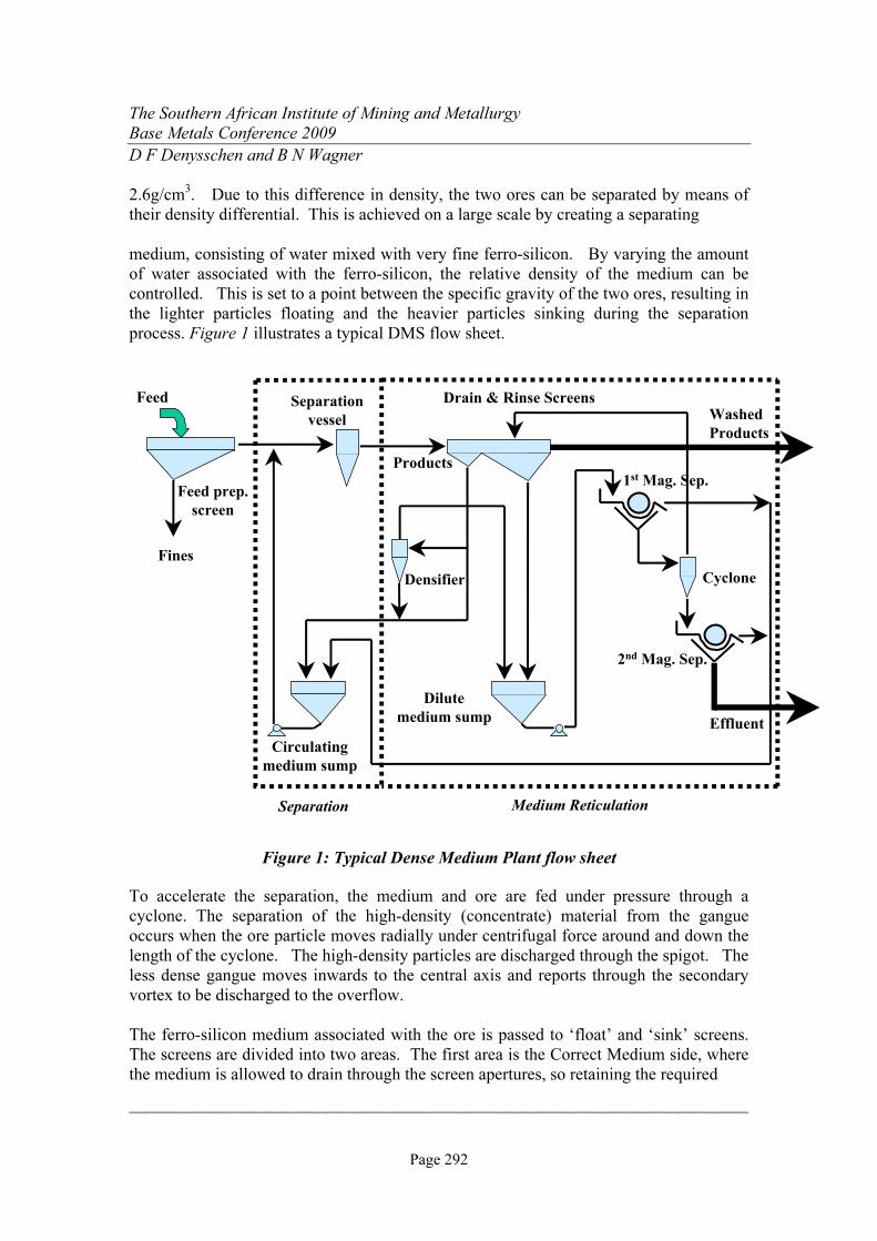
2.6g/cm3. Due to this difference in density, the two ores can be separated by means of
their density differential. This is achieved on a large scale by creating a separating
medium, consisting of water mixed with very fine ferro-silicon. By varying the amount
of water associated with the ferro-silicon, the relative density of the medium can be
controlled. This is set to a point between the specific gravity of the two ores, resulting in
the lighter particles floating and the heavier particles sinking during the separation
process. Figure 1 illustrates a typical DMS flow sheet.
Feed Separation
vessel
Products
Drain & Rinse Screens
1st Mag. Sep.
Washed
Products
Cyclone
2nd Mag. Sep.
Densifier
Fines
Circulating
medium sump
Dilute
medium sump Effluent
Feed prep.
screen
Separation Medium Reticulation
Figure 1: Typical Dense Medium Plant flow sheet
To accelerate the separation, the medium and ore are fed under pressure through a
cyclone. The separation of the high-density (concentrate) material from the gangue
occurs when the ore particle moves radially under centrifugal force around and down the
length of the cyclone. The high-density particles are discharged through the spigot. The
less dense gangue moves inwards to the central axis and reports through the secondary
vortex to be discharged to the overflow.
The ferro-silicon medium associated with the ore is passed to ‘float’ and ‘sink’ screens.
The screens are divided into two areas. The first area is the Correct Medium side, where
the medium is allowed to drain through the screen apertures, so retaining the required

The Southern African Institute of Mining and Metallurgy
Base Metals Conference 2009
D F Denysschen and B N Wagner
________________________________________________________________________
Page 293
operational density for the process. This medium is pumped to a header box and re-
mixed with new feed, before passing back through the cyclone. The second area is the
Dilute Medium side, where spray water is added to wash the adhering ferrosilicon off the
ore, before it is discharged onto separate product and discard conveyor belts. The
medium washed off the ore, which is now dilute, is fed to a magnetic drum separator for
recovery. The recovered medium, normally at a density of 2.4 – 2.6g/cm3, is fed back to
the Correct Medium sump. The effluent from the magnetic separator may be discarded
together with the underflow of the feed preparation screen, or the cleaner water recovered
by classification, and used as wash water on the feed preparation screen.
The retained surface moisture of washed feed and the low medium RD off the magnetic
separator will result in the gradual dilution of the correct medium circuit. A densifier is
added to the correct medium circuit, normally being fed off the Correct Medium header
box or the supply pipeline from the Correct Medium pump to the header box. The
densifier, which is normally a small 100mm diameter cyclone or a 100mm – 200mm pipe
densifier, is used to create over dense medium. This may range from 3.2 to 4.2,
depending on the densifier type selected, operational pressure, medium RD and medium
grade used. The overflow of the densifier is fed to the Dilute Medium circuit, for
medium recovery through the magnetic separator. In order to maintain a steady state
operational medium relative density, the system operates with a water addition valve,
which is controlled automatically.
The Tati Nickel DMS Modules
Two mining areas are sourced at Tati and are identified as Selkirk and Phoenix. The
process plant is situated closer to the Phoenix mining operation. The Selkirk mine is
located some 18 kilometres to the south. Previous mining operations had extracted the
higher grade ore (>2%) from both sources for treatment through a conventional crushing,
milling and flotation circuit.
During the first half of 2006, Tati Nickel embarked on a drilling programme surrounding
the Selkirk mine, which has been on care and maintenance since mining operations
ceased in 2002. The positive results from the first phase of resource evaluation
confirmed the presence of a large disseminated sulphide ore body down-plunge of the
mined-out massive ore body. The bulk of the disseminated sulphides contain nickel
values of around 0.3% with massive sulphide lenses yielding nickel tenors in excess of
2%.
Metallurgical test work was conducted by Mintek, on the drilled bulk samples,
incorporating dense media separation and flotation. Recoveries of 72% were indicated.
Due to the variable grades encountered in the open-cast pit, the mass recovery can vary
from 30 to 75%. This creates an up front discard of material, creating spare capacity
through the milling and concentrator stages of the process. Only the mining, crushing
The Southern African Institute of Mining and Metallurgy
Base Metals Conference 2009
D F Denysschen and B N Wagner
________________________________________________________________________
Page 294
and screening stages require expansion in order to compliment the remainder of the
processes.
The project management was awarded to Dowding Reynard and Associates. In order to
demonstrate the findings above, on a range of run of mine feed grades, a 30 tonne/hour
stand-alone DMS plant was used for preliminary work. This was necessary in order to
finalise the design process route. A high chrome C360 mm Ø cyclone was used on this
module. Cyclone design capacity was 75m3/hour, with a medium: ore ratio of 6.1: 1.
Operational pressure required was 115 kPa.
The follow on was the Phase I expansion DMS, comprising a 160tonne/hour and a
200tonne/hour module. These units are positioned strategically within the existing
process flow.
Phase 1A DMS module
The first module erected was designed for 160tonne/hour HMS feed (approximately
190tonne/hour ROM stockpile feed). The incoming minus 40mm feed was wet screened
at 1mm to remove the associated fines. The screen oversize fed to a mixing box, where
ferrosilicon was added, and pumped to the DMS cyclone. The original design, based on
the work concluded on the 20tonne/hour module, was based on a 50% yield to product.
The options offered, and supplied, were a single high chrome 710mm Ø cyclone, and two
high chrome 510mm Ø cyclones. The 710mm cyclone design capacity was 374m3/hour,
with a medium: ore ratio of 5.5: 1. Operational pressure required was 227 kPa. The
510mm cyclone design capacity was 358m3/hour, with a medium: ore ratio of 5.3: 1.
Operational pressure required was 163 kPa.
The single 710mm Ø cyclone was initially installed. Challenges encountered with this
application were excessively high wear rates on the lower cone section of the cyclone
(see Figure 2), as well as the tangential feed inlet. In these areas, wear rates were being
measured at 2mm per week. The cyclone wall thickness, being 25mm, resulted in areas
holing through at three months operation. The accelerated wear rates were investigated
and attributed to:
• Tati nickel ore being considered within the top ten most abrasive ore bodies in the
world.
• Analysing plant operational data, there were periods where the mass recovery to
the spigot was 80%. As the spigot installed on the 710mm was designed for a
50% yield, spigot constraint occurred, resulting in material not being able to exit
quickly enough.
• Due to the required top size of 40mm, the size of cyclone selected was to be either
two off 510mm Ø or one off 710mm Ø units. Both cyclone options were
purchased, but the 710mm unit, which required an operational pressure of 227kPa
(at 12D) was initially installed and tested. The 510mm units, which would have
required an operational pressure of 163kPa (at 12D) were never installed and
evaluated, especially with respect to reduced wear characteristics.

The Southern African Institute of Mining and Metallurgy
Base Metals Conference 2009
D F Denysschen and B N Wagner
________________________________________________________________________
Page 295
Figure 2: - Wear experienced on high chrome cyclone
Larger diameter spigots were supplied to overcome the over crowding effect. However,
on fitting the spigot size required to accommodate a “worst case” scenario, with an 80%
yield to spigot, there were periods when dropout occurred, resulting in a lower than
expected product grade being produced. A smaller spigot was installed, to help resolve
this problem. The cause of the problem is generally associated with too high medium
density differentials. The density differential, which is calculated as the cyclone
overflow RD divided by the cyclone feed RD, should be within the limits 4 – 9%. If the
value exceeds 9%, the medium is too coarse, resulting in instability. If it is less than 4%,
it is too viscous, as a result of slime contaminants. With density differentials which are
too high, near dense material may find itself too light to report to the underflow, and too
heavy to report to the overflow, resulting in it occupying a transition zone before being
misplaced by the incoming feed, i.e. “dropout”.
The high chrome 710mm Ø unit was replaced with a 710mm Ø alumina tiled cyclone,
which operated for several months until this module was mothballed. A larger spigot was
fitted for this application, to accommodate any spigot constraint which may occur.
Phase 1B DMS module
This module, commissioned some months after 1A, had a feed capacity of
200tonnes/hour cyclone feed, equating to approximately 300-350tonnes/hour of crushed
stockpile feed. The single deck feed preparation screen was fitted with 10mm aperture
panels for the first half, and 40mm panels for the second half. The plus 40mm was
recrushed through the secondary crushers, whilst the minus 10mm was fed directly to the
milling circuit. Only the -40 +10mm material was fed to the cyclone. Here, a single
800mm diameter alumina tiled cyclone was employed.

The Southern African Institute of Mining and Metallurgy
Base Metals Conference 2009
D F Denysschen and B N Wagner
________________________________________________________________________
Page 296
Using the assumption that the -40+10mm fraction was 200tonnes/hour, the cyclone was
pump fed at 15D. At a design of 3.25 for the feed RD, the operational pressure
requirement was 382 kPa. This gives a capacity requirement of 542m3/hour, with a
medium: ore ratio of 7.6: 1. The design yield was 40%.
The high feed pressure required was possibly the greatest challenge on this application.
The cyclone feed pump, delivery pipe and cyclone itself were seen as high wear rate
items. The engineered alumina tiles used on this type of application are 97% alumina,
The tiles are keystone cut, allowing them to fit tightly against each other when pasted
around the arch of the shell circumference. This allows for the minimal of space for an
epoxy filler from the outer to the inner wall of the tile. Hence the wear characteristic
remains the same during the life of the cyclone. However, what was experienced with
the tiles was excessive wear taking place where the cylindrical section enters the twenty
degree conical section. In areas, rapid wear occurred with the epoxy filler, resulting in
“rat holing” between the tiles interface (see Figure 3).
This resulted in undercutting slurry streams on the tiles, causing shear stress on the rear
end, where chipping occurred. This phenomenon occurred on a number of the conical
sections which were installed. The absence of the finer fraction in the particle size
distribution may also have been a contributory factor, as this material helps to cushion the
impact of material along the wall. The cyclone was later supplied as a hybrid version,
with a high chrome conical section and spigot. The tiled inlet head and vortex finder were
retained, where this problem was not experienced (see Figure 4). Unfortunately, this
modification was never fully evaluated, the Phase 1B module being mothballed on
commissioning of the Phase ll plant.
Figure 3 - “Rat holing” of epoxy resin between ceramic tiles

The Southern African Institute of Mining and Metallurgy
Base Metals Conference 2009
D F Denysschen and B N Wagner
________________________________________________________________________
Page 297
Figure 4 - Smooth wear pattern on cyclone inlet chamber
Phase II DMS module
DMS Phase II consists of a 1200 tonne/hour plant. Here four modules are employed,
consisting of two 710mm diameter alumina tiled cyclones per module, (similar to the unit
which replaced the high chrome cyclone on module 1A).
DSE was called upon to fabricate 1215 tons of structural steel and plate-work for this
project. Grinaker LTA MUE Metals and Minerals division was tasked to install all
steelwork and plate-work, together with 477 tonnes of mechanical equipment for the
DMS plant. The plant measures 50 metres long, 27 metres wide and 38 metres high (see
Figure 5).
From the primary and secondary closed circuit crushing and screening section, the ore is
reduced to minus 25mm before storage in a silo. The average mined grade is 0.355% Ni.
From the silo, four separate conveyors feed up into the plant, onto feed preparation
screens (Figure 6). Here, the minus 2mm material is removed, this is then gravity fed to
a 500mm diameter degrit cyclone. The overflow slimes from this degrit cyclone goes to
a thickener, before deposition to tailings. The slimes grade, constituting some 7% by
mass of ROM, assays at 0.5% Ni. The cyclone underflow passes onto a 0.5 x 8.8mm
slotted aperture dewatering screen. The dewatering screen overflow is discharged onto a
conveyor, which feeds to the primary mill feed system. This grit material represents
9.6% of ROM, assays at 0.7% Ni. The dewatering screen underflow feeds to a pulping
tank, which supplies water back to the feed preparation screen feed box.

The Southern African Institute of Mining and Metallurgy
Base Metals Conference 2009
D F Denysschen and B N Wagner
________________________________________________________________________
Page 298
Figure 5 - Phase ll DMS Plant
Figure 6 - Feed conveyor system from storage silo
The overflow of the feed preparation screen feeds into the mixing box, where medium is
added, before gravitating down to two 710mm diameter alumina tiled cyclones. Each
module has separate drain and rinse screens. The sinks (product) reports to its own
vibratory screen, whilst the floats (discard) flows over a static screen before reporting to a
vibratory screen. As per conventional units, the drain and rinse screens have a correct
and dilute medium side. The correct medium is pumped back up into a header tank,
The Southern African Institute of Mining and Metallurgy
Base Metals Conference 2009
D F Denysschen and B N Wagner
________________________________________________________________________
Page 299
located in the top of the plant, for distribution into the mixing box and densifiers (three
off 200mm diameter units for each module).
The dilute medium screen underflow is pump fed to a magnetic separator; the recovered
medium is discharged back into the correct medium sump, the effluent going to the
dewatering screen underflow pulping tank.
The DMS product, which assays at 0.46% Ni, and represents 49% of ROM, is conveyed
to a storage silo to feed the primary mill. The DMS discard is conveyed to the waste
dump for disposal. This assays at 0.08% Ni, and represents 35% of ROM.
Each cyclone was selected based on a screened feed of 180tonnes/hour, at 14D (267kPa).
This is a static head requirement of 9.9 meters, excluding the systems frictional and
restriction losses. Cyclone capacity is 420 m3/hour, offering a medium: ore ratio of 6.0: 1.
The Process Flow Diagrams of each DMS Module (Appendix 1) and the thickener circuit
(Appendix 2) are shown below.
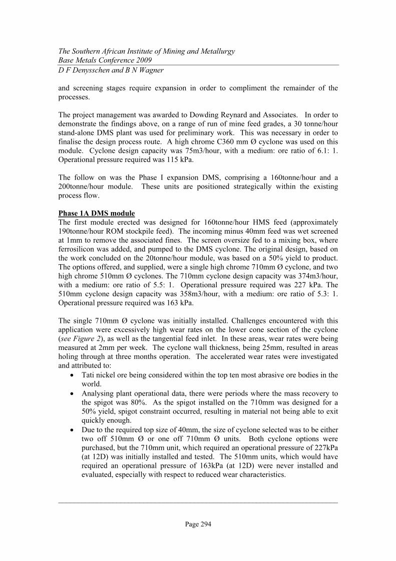
The cyclone installation layout is shown below in Figure 7.
Figure 7 - 710mm DMS cyclone modules
To date, the following operational challenges have been identified:
The Southern African Institute of Mining and Metallurgy
Base Metals Conference 2009
D F Denysschen and B N Wagner
________________________________________________________________________
Page 300
• The physical height of 38 meters for a gravity fed plant requires the pumping of
ferrosilicon, at a RD of 3.25, to a water head equivalent of 75 meters. This places
severe strain on a single stage pumping process, especially with respect to gland
service supply water pressure. Currently problems are experienced with sliming
of pumps, resulting in an excessive amount of ferrosilicon discharging onto the
ground. This may become costly due to additional handling to get the medium
back into the circuit as well as the loss due to its oxidisation.
• The abrasiveness of the ore presents excessively high wear rate conditions,
especially in chutes, piping and static screen panels.
• Due to the high medium density, ferrosilicon settles out in the header box,
resulting in build up in certain areas. The result is the box overflows and requires
removal of material build up to get back to normal.
• As the ore contains 70% pyrrhotite, the feed preparation process must be as
efficient as possible to remove adhering fines and grit. This material is magnetic,
and if it contaminates the medium it will be recovered on the magnetic separator
and introduced back into the correct medium sump. As the pyrrhotite has a lower
density than ferrosilicon, too much contamination (15 to 20%) will result in it
being necessary to remove more water from the correct medium in order to
achieve the same operational relative density. This becomes undesirable with
respect to the separation characteristics achieved in the cyclone. A method of
effective removal of this contaminant is still under investigation.
Summary
Recovery values which have been realised are given in Appendix 3.
Nickel grade
High grade nickel mined ore is defined as material typically above 0.56% Ni, which is
fed directly to the mills. A provision is made to the circuit to crush, screen and stockpile
this material separately. Currently the blend of opencast material assays at 0.31 – 0.37%
Ni. After wet screening out the minus 1mm fines, the DMS feed grade drops to 0.27 –
0.32% Ni. It is not desirable for this grade to go lower than 0.20% Ni as the desired
upgrade ratio is not achievable. Currently, upgrade ratios achieved are 1.38 – 1.62. A
ratio of 1.80 would be more favourable, but would only be achieved by crushing smaller.
The DMS product assays at 0.41 – 0.50% Ni, with the waste at 0.07 – 0.09% Ni.
The screened minus 1mm fines material is cut through a degrit cyclone at approximately
150 micron. The slimes (-150 micron) assays at 0.5% Ni, which is discarded to the slimes
dam. The grit (+150 micron) assays at 0.7% Ni, and is fed to the milling circuit.

The Southern African Institute of Mining and Metallurgy
Base Metals Conference 2009
D F Denysschen and B N Wagner
________________________________________________________________________
Page 301
Nickel distribution
The DMS product currently recovers 63.1% of the nickel into 48.7% of the mass. The
DMS discard, which is 34.6% of the mass, contains 8.3% of the nickel.
The discard slimes, 6.9% by mass, contains 10% of the nickel. The recovered grit is
9.6% by mass, containing 18.6% of the nickel.
The combined nickel extracted (DMS product and grit) which is fed to the milling circuit
is 81.7%, which is in 58.3% of the original mass.
The table below indicates that the DMS option has increased the milling and flotation
metal units capacity by 45%. Please note that the slimes portion has been excluded in
the calculation.
% Ni Mass Ni units
No DMS 0.343 93.02 31.95
With DMS 0.497 58.37 29.03
Capacity grade 0.497 93.02 46.27
Capacity increase 45%
Pre concentration of ore has always been seen as an operation which runs on a fine line
between feed capacity and grades, and upgrade ratio and mass capabilities with respect to
operational cost and revenue generated. Obviously due to the current global economic
downturn, which has had an impact on metals prices, the cut off grade at which low grade
ores can be economically treated is under severe pressure. Due to the sensitivity of the
current market conditions, no financials have been disclosed in this paper.
Acknowledgements
Chris Viljoen (Process Development Manager, Tati Nickel)
Michael Musonda (Senior Plant Metallurgist, Tati Nickel)
References
www.lionore.com\operations\tatinickel.asp
www.lionore.com\oeprations\activox.asp
www.engineeringnews.co.za
http://africa.com\stories
http://findarticles.com\p\articles
The Southern African Institute of Mining and Metallurgy
Base Metals Conference 2009
D F Denysschen and B N Wagner
________________________________________________________________________
Page 302
APPENDIX 1
The Southern African Institute of Mining and Metallurgy
Base Metals Conference 2009
D F Denysschen and B N Wagner
________________________________________________________________________
Page 303
APPENDIX 2

The Southern African Institute of Mining and Metallurgy
Base Metals Conference 2009
D F Denysschen and B N Wagner
________________________________________________________________________
Page 304
APPENDIX 3
Feed Grit Slimes Floats Sinks
August 2008 100.00 9.46 6.39 37.59 46.56
September 2008 100.00 10.43 7.18 38.92 43.47
October 2008 100.00 9.92 7.64 30.63 51.81
November 2008 100.00 8.84 7.30 28.54 55.32
December 2008 100.00 9.46 6.39 37.59 46.56
Five month ave 100.00 9.62 6.98 34.65 48.74
Feed Grit Slimes Floats Sinks
August 2008 0.370 0.762 0.507 0.094 0.495
September 2008 0.313 0.564 0.441 0.082 0.439
October 2008 0.361 0.618 0.535 0.070 0.459
November 2008 0.359 0.738 0.549 0.080 0.418
December 2008 0.370 0.762 0.507 0.094 0.495
Five month ave 0.355 0.689 0.508 0.084 0.461
Feed Grit Slimes Floats Sinks
August 2008 100.0 19.5 8.7 9.6 62.2
September 2008 100.0 18.8 10.1 10.2 60.9
October 2008 100.0 17.0 11.3 5.9 65.8
November 2008 100.0 18.2 11.2 6.3 64.4
December 2008 100.0 19.5 8.7 9.6 62.2
Five month ave 100.0 18.6 10.0 8.3 63.1
Yield
August 2008 55.3%
September 2008 52.8%
October 2008 62.8%
November 2008 66.0%
December 2008 55.3%
Five month ave 58.4%
1.57
1.52
Upgrade ratio Nickel recovery
86.7%
85.6%
91.7%
91.1%
86.7%
88.3%
1.57
1.62
1.46
1.38
Mass distribution (%)
Nickel grade (%)
Nickel distribution (%)
DMS Plant
The Southern African Institute of Mining and Metallurgy
Base Metals Conference 2009
D F Denysschen and B N Wagner
________________________________________________________________________
Page 305
The Author
Barend N. Wagner (Nico), Senior Process Engineer- Cyclones, MULTOTEC Process
Equipment
2008 – Present:
Multotec Process Equipment: Senior process engineer - Cyclones department.
Focus on dense medium separation and classification applications.
2006-2008
Minopex: Plant Metallurgist - Letseng diamond mine in Lesotho.
Was responsible for the management of all day-to-day production issues of the
DMS concentrator plant.
2001-2006
DMS Powders: Production superintendent - Ferrosilicon production plant.
Production supervision and later management of submerged arc furnace and ball
mill sections of the smelter plant
1999-2001
Messer Fedgas: Metallurgical applications engineer – Marketing division
Optimisation and problem solving of a variety of metallurgical processes
including gold extraction, metal refining, heat treatment and combustion
applications, employing metallurgical grade technical gases.
1997-1999
Highveld Steel & Vanadium: Metallurgist - Metallurgical Quality Control Division.
Conducted day-to-day destructive and non-destructive QC tests on production
samples from the Steel plant and hot rolling mills. Was also responsible for
metallurgical failure investigations on supplied product to industry.

The Southern African Institute of Mining and Metallurgy
Base Metals Conference 2009
D F Denysschen and B N Wagner
________________________________________________________________________
Page 306