practice note for authorized persons, registered ... · buildings department practice note for...
TRANSCRIPT
Buildings Department Practice Note for Authorized Persons, Registered Structural Engineers and Registered Geotechnical Engineers
APP-93
Planning and Design of Drainage Works
This practice note sets out the requirements for the planning and design
of drainage works for new buildings.
Introduction 2. In the course of carrying out drainage repair and maintenance, difficulties have often been encountered in obtaining access to both the underground drains and above ground drainage pipes which run under/inside private premises such as shops (in particular restaurants and restaurant kitchens) and domestic units under separate occupancies. Both investigation and repair works, which may necessitate entry into private premises, opening up of floor slabs, and trench excavations, will cause much inconvenience to the occupants. In the worst cases, the premises may have to be closed to effect the repair works. Improvement 3. In order to obviate such access difficulties and to facilitate the future maintenance of common drains, I shall require under section 28(1) of the Buildings Ordinance that the following be complied with: -
(a) Except drains in car-parking floors, all common underground drains for new buildings shall run in a space or land which is ‘sterilized’ or otherwise designated as common parts of the building;
(b) Where internal common soil and waste stacks are proposed in
domestic buildings not intended for single occupancy, such stacks shall be located in the common parts of the building. Where pipe-ducts or pipe wells are proposed to house common soil and waste stacks, they shall satisfy the following criteria respectively : -
(i) Pipe Ducts
(1) These pipe-ducts shall be accessible from the common parts of the building;
(2) An unobstructed working space, of not less than 700 mm in front of the pipes, shall be provided for maintenance and repair of the pipeworks; and
/(3) …..
- 2 -
(3) The doors or panels providing access to the pipe-ducts shall not be less than 600 mm wide by 2000 mm high and shall comply with Part C of the Code of Practice for Fire Safety in Buildings 2011.
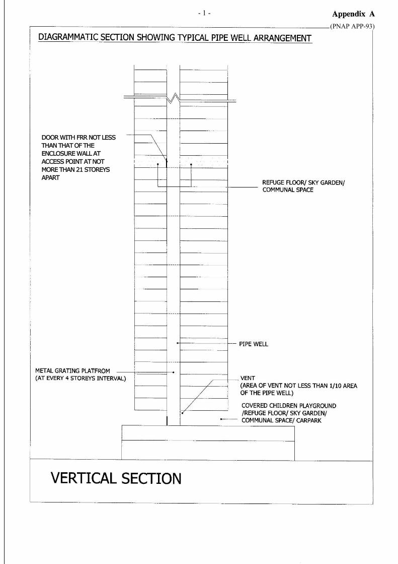
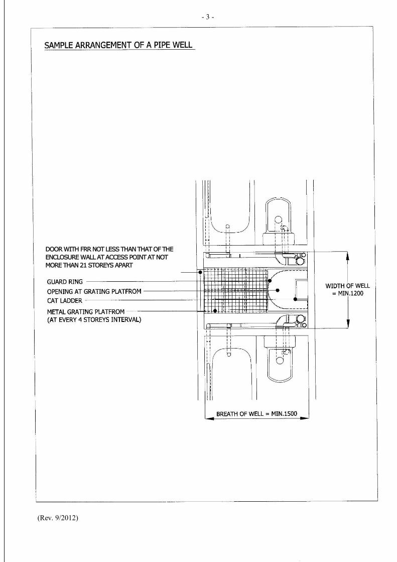
(ii) Pipe Wells
(1) The size of pipe well shall not be less than 1200 mm x 1500 mm;
(2) No opening will be allowed in a pipe well other than access points for inspection and maintenance, which shall be from the common parts of the building. Access points shall be provided to the pipe well at not more than 21 storeys apart;
(3) Cat ladder with proper guard rings shall be installed in the full height of the pipe well for inspection and maintenance purposes;
(4) Grating platforms shall be provided at intervals of not more than 4 storeys;
(5) The opening at every access point shall not be less than 600 mm wide by 2000 mm high and shall comply with Part C of the Code of Practice for Fire Safety in Buildings 2011; and
(6) A ventilation opening having a minimum net area of 1/10th of the horizontal area of the pipe well shall be provided at both the top and bottom of the pipe well;
Subject to paragraph 4 below, the area of pipe ducts and pipe wells could be exempted from the gross floor area (GFA) calculations. Open pipe wells may also be exempted from site coverage calculations. A sample illustration of the design of a pipe well is attached at Appendix A for general reference.
(c) The lowest level of re-entrants and light wells housing external soil and waste stacks shall be designated as common parts of the building and such parts shall be provided with adequate access which could be in the form of cat-ladder where necessary, for carrying out maintenance works and cleansing;
(d) For domestic buildings other than those intended for single
occupancy or single family residence, no pipeworks for a unit shall protrude into the unit under separate occupancy on the floor below;
/(e) …..
- 3 -
(e) Except for buildings not more than three storeys high, separate pipework discharging to a manhole shall be provided to serve the sanitary fitments at the floor, which is at the same level as the bottom of the waste/foul water stack;
(f) The nominal diameter of every soil pipe from water closet
fitments or slop sinks shall be not less than the diameter of the outlet of any of the fitments it serves; and
(g) Soil and wastewater pipes shall only have bends where a change
in direction is unavoidable. The radius of the bends at the bottom of stacks shall under no circumstances be less than four times the radius of the stack measured from the centerline whenever practicably possible, but under no circumstances be less than 200 mm measured from the centerline.
4. If the pipe ducts and/or pipe wells are proposed to house pipes for rainwater, soil and wastewater disposal, as well as other pipeworks which are part of the distribution network for non-mandatory feature / non-essential plant room1, the exemption described in paragraph 3(b) above may only be granted subject to compliance with the pre-requisites and the overall cap on GFA concessions stipulated in PNAP APP-151 on Building Design to Foster a Quality and Sustainable Built Environment. 5. To provide flexibility in the design of pipeworks to satisfy the requirement set out in paragraph 3(d) above, the Building Authority is prepared to consider an application for modification of regulation 25(1) of the Building (Standards of Sanitary Fitments, Plumbing, Drainage Works and Latrines) Regulations to permit the total length of pipeworks from a bathtub or shower tray to a trap up to 750 mm at a minimum gradient of 1:40. If sunken slab design is adopted for accommodating pipeworks (including both vertical and horizontal pipes) associated with bathroom/lavatory/kitchen in domestic units, the void space between the floor finish and the sunken slab shall not be backfilled with concrete or similar materials which may cause obstruction to future repair and maintenance of the pipeworks. On occasions where the backfilling of such void space is unavoidable, sufficient access points (such as by means of access panels of appropriate size and/or cleaning eyes extended to the finished floor level from such pipeworks) should be provided to facilitate inspection of every part of such pipeworks and clearance of any blockage thereof. To cater for inspection of such pipeworks in the void space in future, arrangement can be made for such inspection to be carried out with the assistance of appropriate device (such as portable type camera or CCTV imaging device) through the access points. Authorized Persons (APs) are also advised to draw the attention of building owners that the floor finish of the sunken slab design may need to be opened up and subsequently reinstated for the carrying out of pipe repair and maintenance works (such as pipe replacement or repairing of leaking joints) as necessary in future.
/6. …… 1 See PNAP APP-151 on examples of non-mandatory feature / non-essential plant room.
- 4 - 6. Reference shall be made to PNAP ADV-14 on the facilities for the maintenance of external building drainage pipes. Consideration for separate pipes in zones for high rise buildings shall also be made in the design stage for future maintenance and repair. 7. If architectural features are proposed to enclose external drainage pipes for achieving a better elevation design, the AP should provide an effective arrangement for visual inspection of the pipes including pipe connexions, fixing of pipes, etc. to enable the detection or inspection of any defect, leakage or insanitary condition of the pipes in a convenient and safe manner, where necessary. The access for inspections and maintenance should be from the common parts of the building and shown on the submitted drainage plans and incorporated in the corresponding building plans. An example of an effective arrangement is provided at Appendix B for reference. For the avoidance of doubt, pipes partially screened by architectural features complying with the criteria in Appendix C are not regarded as enclosed by architectural features for the purpose of this paragraph. 8. While the requirement set out in paragraph 3(d) does not apply to non-domestic premises, APs are encouraged to adopt the same arrangement, wherever possible, for drainage pipes in such premises.
( HUI Siu-wai )
Building Authority Ref. : BD GP/BORD/21 (III) BDGP/BREG/P/49 (V) BD GP/BORD/21 (IV) This PNAP is previously known as PNAP 211 First issue August 1997 Last revision September 2012 This revision May 2014 (AD/NB1) (Para. 7, Appendices B & C added and
previous para. 8 deleted)
(PNAP APP-93)
DOOR WITH FRR NOT LESS THAN THAT OF THE ENCLOSURE WALL AT ACCESS POINT AT NOT MORE THAN 21 STOREYS APART
- 1 -

DOOR WITH FRR NOT LESS THAN THAT OF THE ENCLOSURE WALL AT ACCESS POINT AT NOT MORE THAN 21 STOREYS APART
- 2 -
AT
DOOR WITH FRR NOT LESS THAN THAT OF THE ENCLOSURE WALL AT ACCESS POINT AT NOT MORE THAN 21 STOREYS APART
(Rev. 9/2012)
- 3 -
- 1 -
Appendix B (PNAP APP-93)
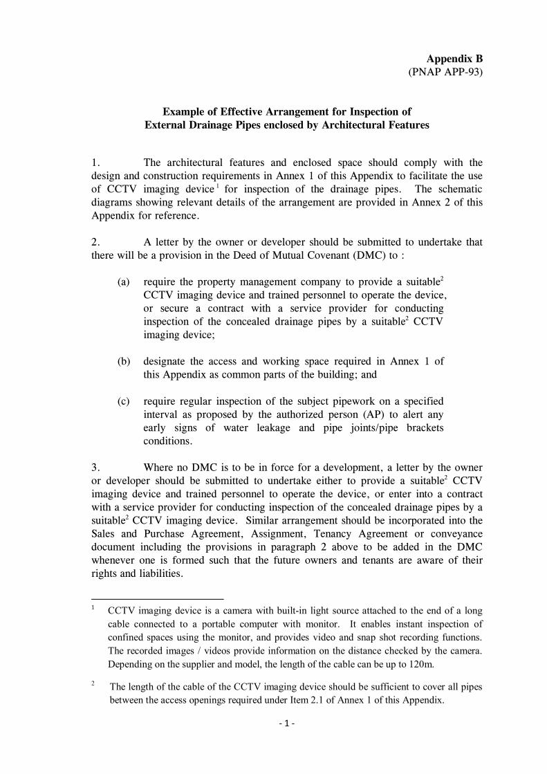
Example of Effective Arrangement for Inspection of External Drainage Pipes enclosed by Architectural Features
1. The architectural features and enclosed space should comply with the design and construction requirements in Annex 1 of this Appendix to facilitate the use of CCTV imaging device 1 for inspection of the drainage pipes. The schematic diagrams showing relevant details of the arrangement are provided in Annex 2 of this Appendix for reference. 2. A letter by the owner or developer should be submitted to undertake that there will be a provision in the Deed of Mutual Covenant (DMC) to :
(a) require the property management company to provide a suitable2 CCTV imaging device and trained personnel to operate the device, or secure a contract with a service provider for conducting inspection of the concealed drainage pipes by a suitable2 CCTV imaging device;
(b) designate the access and working space required in Annex 1 of
this Appendix as common parts of the building; and (c) require regular inspection of the subject pipework on a specified
interval as proposed by the authorized person (AP) to alert any early signs of water leakage and pipe joints/pipe brackets conditions.
3. Where no DMC is to be in force for a development, a letter by the owner or developer should be submitted to undertake either to provide a suitable2 CCTV imaging device and trained personnel to operate the device, or enter into a contract with a service provider for conducting inspection of the concealed drainage pipes by a suitable2 CCTV imaging device. Similar arrangement should be incorporated into the Sales and Purchase Agreement, Assignment, Tenancy Agreement or conveyance document including the provisions in paragraph 2 above to be added in the DMC whenever one is formed such that the future owners and tenants are aware of their rights and liabilities.
1 CCTV imaging device is a camera with built-in light source attached to the end of a long
cable connected to a portable computer with monitor. It enables instant inspection of confined spaces using the monitor, and provides video and snap shot recording functions. The recorded images / videos provide information on the distance checked by the camera. Depending on the supplier and model, the length of the cable can be up to 120m.
2 The length of the cable of the CCTV imaging device should be sufficient to cover all pipes between the access openings required under Item 2.1 of Annex 1 of this Appendix.
- 2 -
4. Upon completion of the installation of the architectural features and prior to an application for an occupation permit, the external drainage pipes concealed by the architectural features should be inspected by a CCTV imaging device under the supervision of the AP or his representative who should subsequently endorse the inspection results on site. In support of the application for an occupation permit, the AP should submit a “certificate on completion of inspection of drainage pipes concealed by architectural features” in Annex 3 of this Appendix together with the endorsed inspection records. (5/2014)
- 1 -
Annex 1 of Appendix B (PNAP APP-93)
Construction and Design Requirements
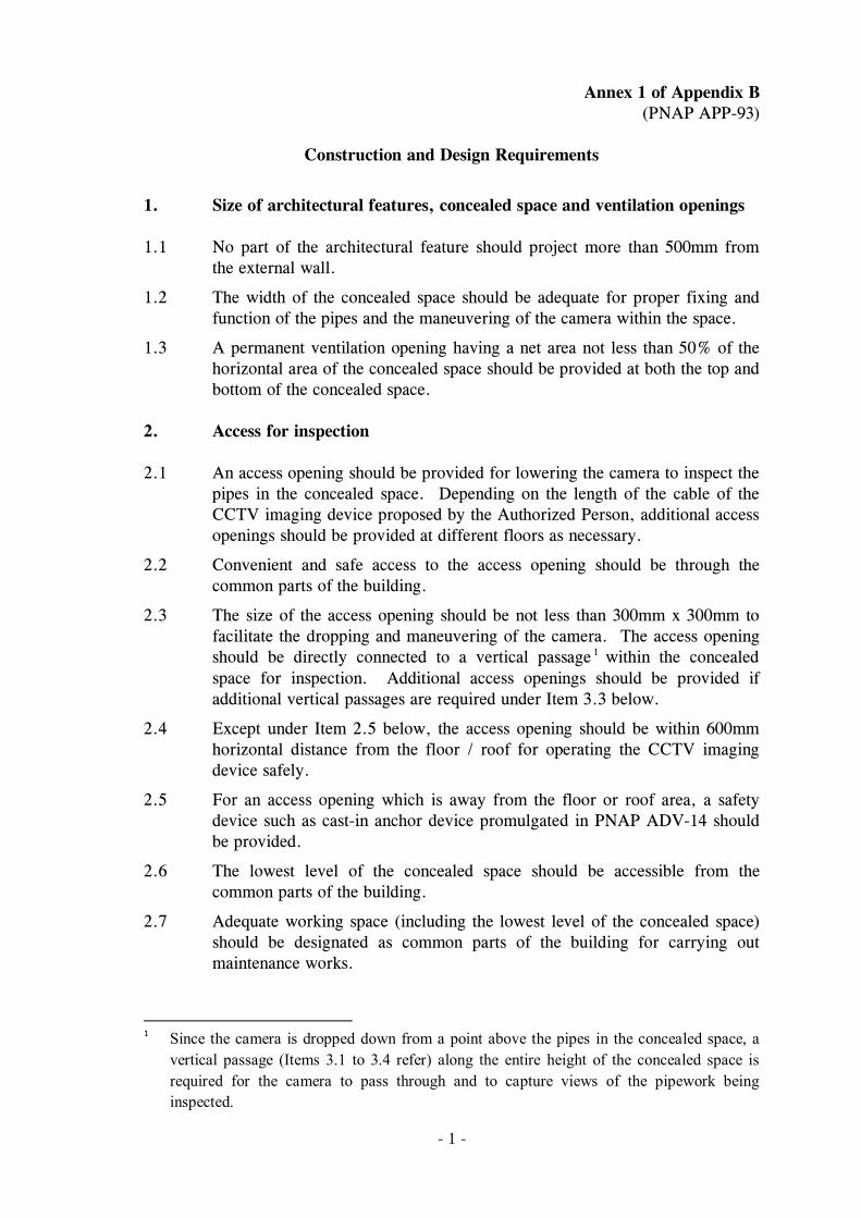
1.
Size of architectural features, concealed space and ventilation openings
1.1 No part of the architectural feature should project more than 500mm from the external wall.
1.2 The width of the concealed space should be adequate for proper fixing and function of the pipes and the maneuvering of the camera within the space.
1.3 A permanent ventilation opening having a net area not less than 50% of the horizontal area of the concealed space should be provided at both the top and bottom of the concealed space.
2. Access for inspection
2.1 An access opening should be provided for lowering the camera to inspect the pipes in the concealed space. Depending on the length of the cable of the CCTV imaging device proposed by the Authorized Person, additional access openings should be provided at different floors as necessary.
2.2 Convenient and safe access to the access opening should be through the common parts of the building.
2.3 The size of the access opening should be not less than 300mm x 300mm to facilitate the dropping and maneuvering of the camera. The access opening should be directly connected to a vertical passage 1 within the concealed space for inspection. Additional access openings should be provided if additional vertical passages are required under Item 3.3 below.
2.4 Except under Item 2.5 below, the access opening should be within 600mm horizontal distance from the floor / roof for operating the CCTV imaging device safely.
2.5 For an access opening which is away from the floor or roof area, a safety device such as cast-in anchor device promulgated in PNAP ADV-14 should be provided.
2.6
2.7
The lowest level of the concealed space should be accessible from the common parts of the building.
Adequate working space (including the lowest level of the concealed space) should be designated as common parts of the building for carrying out maintenance works.
1 Since the camera is dropped down from a point above the pipes in the concealed space, a
vertical passage (Items 3.1 to 3.4 refer) along the entire height of the concealed space is required for the camera to pass through and to capture views of the pipework being inspected.
- 2 -
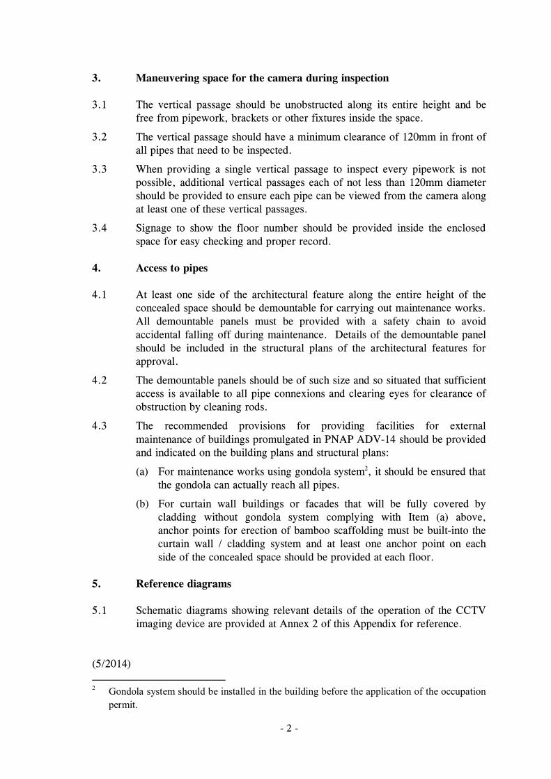
3. Maneuvering space for the camera during inspection
3.1 The vertical passage should be unobstructed along its entire height and be free from pipework, brackets or other fixtures inside the space.
3.2 The vertical passage should have a minimum clearance of 120mm in front of all pipes that need to be inspected.
3.3 When providing a single vertical passage to inspect every pipework is not possible, additional vertical passages each of not less than 120mm diameter should be provided to ensure each pipe can be viewed from the camera along at least one of these vertical passages.
3.4 Signage to show the floor number should be provided inside the enclosed space for easy checking and proper record.
4. Access to pipes
4.1 At least one side of the architectural feature along the entire height of the concealed space should be demountable for carrying out maintenance works. All demountable panels must be provided with a safety chain to avoid accidental falling off during maintenance. Details of the demountable panel should be included in the structural plans of the architectural features for approval.
4.2 The demountable panels should be of such size and so situated that sufficient access is available to all pipe connexions and clearing eyes for clearance of obstruction by cleaning rods.
4.3 The recommended provisions for providing facilities for external maintenance of buildings promulgated in PNAP ADV-14 should be provided and indicated on the building plans and structural plans:
(a) For maintenance works using gondola system2, it should be ensured that the gondola can actually reach all pipes.
(b) For curtain wall buildings or facades that will be fully covered by cladding without gondola system complying with Item (a) above, anchor points for erection of bamboo scaffolding must be built-into the curtain wall / cladding system and at least one anchor point on each side of the concealed space should be provided at each floor.
5. Reference diagrams
5.1 Schematic diagrams showing relevant details of the operation of the CCTV
imaging device are provided at Annex 2 of this Appendix for reference. (5/2014) 2 Gondola system should be installed in the building before the application of the occupation
permit.
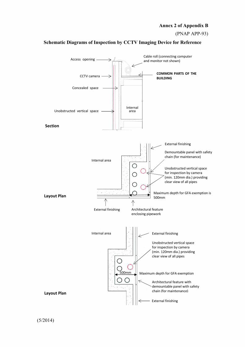
Annex 2 of Appendix B
(PNAP APP-93)
Schematic Diagrams of Inspection by CCTV Imaging Device for Reference
(5/2014)
CCTV camera
Concealed space
Unobstructed vertical space
Access opening Cable roll (connecting computer and monitor not shown)
COMMON PARTS OF THE BUILDING
Internal area
Section
Internal area
Layout Plan
External finishing
Demountable panel with safety chain (for maintenance)
Unobstructed vertical space for inspection by camera (min. 120mm dia.) providing clear view of all pipes
External finishing Architectural feature enclosing pipework
Layout Plan
Internal area
External finishing
Unobstructed vertical space for inspection by camera (min. 120mm dia.) providing clear view of all pipes
Architectural feature with demountable panel with safety chain (for maintenance)
External finishing
500mm
Maximum depth for GFA exemption is 500mm
Maximum depth for GFA exemption

Annex 3 of Appendix B (PNAP APP-93)
Certificate on Completion of Inspection of Drainage Pipes Concealed by Architectural Features
BD Ref. :
Date :
Re : __________________________________________________________
(Address and lot description of development site)
To the Building Authority,
I, (name in full) _______________________________, authorized person confirm that * I / my representative ( ______________________________________ ) had witnessed the inspection of drainage pipes concealed by architectural features which was carried out at the captioned site on . Pursuant to Appendix B of PNAP APP-93 and regulation 44 of the Building (Administration) Regulations, I submit the inspection results with record plans of drainage pipes inspected, duly endorsed by me, in support of my Form BA 13 submission dated . 2. I certify that the above inspection has been properly carried out and I am satisfied with the results of the inspection.
Signature# of authorized person
Certificate of Registration No. #:
Date of expiry of registration#:
c.c. Registered General Building Contractor * Delete whichever is inapplicable # In accordance with the registration record (5/2014)

Appendix C (PNAP APP-93)
Criteria for Partial Screening of External Drainage Pipes by Architectural Features
1. The pipes should be exposed to the external at least on one side in accordance with
Item 2 below and should not be obstructed by other building services, fittings or fixtures in accordance with Figure A;
2. The exposed side may be screened by permeable architectural features of not less than 70% permeability* subject to the provision of a vertical zone with a minimum height of 800 mm at each floor level such that the pipes and branch pipes for that floor will not be screened by any architectural feature (Figure B refers); and
3. No part of the permeable architectural features should project more than 500mm from the external wall.
Figure A : Layout Plans of Exposed Pipes
Figure B : Elevation of Architectural Features on the Exposed Side
________________________ * Permeability means the visual and physical porosity of the architectural features.
(5/2014)
(unacceptable as the outermost pipe screening off the pipes behind)
(acceptable drainage pipe layout may be provided with permeable architecture features)
Permeable architectural features of not less than 70% permeability*
Minimum 800 mm high vertical zone exposing the pipes and branch pipes to be provided for each floor
PIPES
EXTERNAL WALL
ARCHITECTURE FEATURE
INSIDE OUTSIDE INSIDE OUTSIDE
PIPES
EXTERNAL WALL
ARCHITECTURE FEATURE
TYPICAL FLOOR
TYPICAL FLOOR
TYPICAL FLOOR