practical lighting design with leds (lenk/practical lighting design) || light bulbs and lighting...
TRANSCRIPT
13
Chapter 2
Light Bulbs and Lighting Systems
This book is about lighting design with LEDs. While the rest of the book is about the LED part, in this chapter we present some background on the lighting part. The reason for this is that light bulbs have been around for more than 100 years. In that time, there have been many people working on them, and much technology has been developed. While we can ’ t claim that this is a comprehensive survey, there ’ s prob-ably information in this chapter that you ’ ll be happy you have.
A few words about terminology are in order. Wikipedia 1 says that “ A lamp is a replaceable component such as an incandescent light bulb, which is designed to produce light from electricity. ” As you can see, there is a general confusion about what to call light - producing devices. Most consumers call the device a light bulb , and the unit that holds it a lamp. Manufacturers usually call the device a lamp, and the unit holding it a fi xture . In this book, we will usually try to follow consumer usage. But the reader should be aware of the difference when reading publications.
LIGHT SOURCES
Incandescent
Light - emitting diodes are merely the newest in a long list of different types of light-ing devices. Ignoring truly ancient devices such as candles, all of them use electric-ity. The fi rst and still most common light source is incandescent. An incandescent bulb works by heating a piece of metal, the fi lament, until it glows. By adjusting the power level, it can be made to glow different colors. The typical incandescent fi lament runs at about 2850 K, resulting in the familiar yellow color. 2 When you
1 http://en.wikipedia.org/wiki/Lamp_(electrical_component ), under license. Accessed December 2010. http://creativecommons.org/licenses/by - sa/3.0/
2 Could a consumer device that runs at half the temperature of the surface of the sun be introduced to the market today? And by the way, fl uorescent tube plasma runs at 1100 ° K, much hotter than your oven.
Practical Lighting Design With LEDs, First Edition. Ron Lenk, Carol Lenk.© 2011 the Institute of Electrical and Electronics Engineers, Inc. Published 2011 by John Wiley & Sons, Inc.
c02.indd 13c02.indd 13 2/10/2011 10:13:34 AM2/10/2011 10:13:34 AM
14 Chapter 2 Light Bulbs and Lighting Systems
dim the bulb it receives less power. This not only produces less light, it also reduces the temperature of the fi lament. This is why dimmed incandescent bulbs look reddish.
Note that the glass shell in an incandescent bulb is used to maintain a partial vacuum, preventing the fi lament from oxidizing and failing. There has been some research into altering the mixture of remaining gas in the shell to enhance bulb life.
The incandescent bulb runs very hot. The surface temperature of a 40 W runs about 120 ° C. That ’ s why you have to wait a bit after turning it off to touch it. The common failure mode for an incandescent is for its fi lament to break. This typically happens after about 1000 hours of operation. Switching incandescent bulbs on and off a lot can also cause the fi lament to fail, but in typical operation this is not the dominant failure mechanism.
Before leaving the topic of incandescent light sources, a comment on safety is in order. If you unscrew an incandescent bulb from its socket without turning off the light switch, sticking your fi nger in the socket will connect you with 120VAC. This is life - threatening. If you try to hold an incandescent bulb when it ’ s on, it will burn you. It ’ s hard to imagine a device with these sorts of extreme problems being introduced today. Conversations with engineers at UL suggest that incandescent bulbs are “ grandfathered in. ” They were there before regulations existed, and so they can ’ t be easily eliminated. But it certainly seems like the time has come for engineers to come up with something better.
Halogen
Halogen bulbs are also incandescent. The difference between halogen and normal incandescent bulbs is that halogens contain a small amount of halogen. The halogen makes the fi lament burn hotter, which slightly increases the effi cacy of the bulb. It also makes the CCT higher than in a normal incandescent. An additional benefi t is that the halogen helps the fi lament to survive longer (by redepositing the fi lament material).
Fluorescent
Fluorescent bulbs work entirely differently from incandescent bulbs. They too have a partial vacuum inside a glass tube. In this case, though, the tube intentionally has some mercury vapor in it. When the fi lament inside the bulb is heated, it emits electrons. These ionize the mercury, forming a plasma arc at about 1100 K. The mercury emits UV light to go back to its normal state. The UV light hits a phosphor coated on the glass tube. This is the white coating on fl uorescents. The phosphor absorbs the UV light, and emits visible light, which is the output of the bulb. The phosphor is carefully designed to produce just the color light that is desired, and is usually a mix of different phosphors.
To run this complicated device requires a special circuit called a ballast . The ballast is connected to the AC line as input, normally either 120 or 277VAC in the
c02.indd 14c02.indd 14 2/10/2011 10:13:34 AM2/10/2011 10:13:34 AM
Light Sources 15
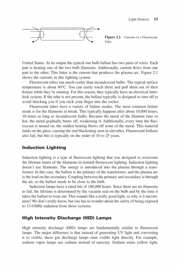
United States. At its output the typical one bulb ballast has two pairs of wires. Each pair is heating one of the two bulb fi laments. Additionally, current fl ows from one pair to the other. This latter is the current that produces the plasma arc. Figure 2.1 shows the currents in this lighting system.
Fluorescent tubes run much cooler than incandescent bulbs. The typical surface temperature is about 40 ° C. You can easily touch them and pull them out of their fi xture while they ’ re running. For this reason, they typically have an electrical inter-lock system. If the tube is not present, the ballast typically is designed to turn off to avoid shocking you if you stick your fi nger into the socket.
Fluorescent tubes have a variety of failure modes. The most common failure mode is for the fi laments to break. This typically happens after about 10,000 hours, 10 times as long as incandescent bulbs. Because the metal of the fi lament runs so hot, the metal gradually burns off, weakening it. Additionally, every time the fl uo-rescent is turned on, the sudden heating blows off some of the metal. This material lands on the glass, causing the end blackening seen in old tubes. Fluorescent ballasts also fail, but this is typically on the order of 10 to 25 years.
Induction Lighting
Induction lighting is a type of fl uorescent lighting that was designed to overcome the lifetime limits of the fi laments in normal fl uorescent lighting. Induction lighting doesn ’ t use fi laments. The energy is introduced into the plasma through a trans-former. In this case, the ballast is the primary of the transformer, and the plasma arc is the load on the secondary. Coupling between the primary and secondary is through the air, so the ballast needs to be close to the bulb.
Induction lamps have a rated life of 100,000 hours. Since there are no fi laments to fail, the lifetime is determined by the vacuum seal on the bulb and by the time it takes the ballast to wear out. This sounds like a really good light, so why is it uncom-mon? We don ’ t really know, but one has to wonder about the safety of being exposed to 13.6 MHz radiation from these systems.
High Intensity Discharge (HID) Lamps
High intensity discharge (HID) lamps are fundamentally similar to fl uorescent lamps. The major difference is that instead of generating UV light and converting it to visible, these gas discharge lamps emit visible light directly. For example, sodium vapor lamps use sodium instead of mercury. Sodium emits yellow light,
Figure 2.1 Currents in a Fluorescent Tube.
c02.indd 15c02.indd 15 2/10/2011 10:13:34 AM2/10/2011 10:13:34 AM
16 Chapter 2 Light Bulbs and Lighting Systems
which is often seen in lights in parking lots. The term “ HID ” covers a variety of lamps that differ in the material used to generate the light, such as metal halide, sodium vapor, and xenon.
Because there is one less conversion step in these bulbs, HID bulbs tend to be more effi cient than standard fl uorescent tubes. They can be 100 Lm/W versus 60 Lm/W for fl uorescent tubes. As with all lighting, there is a trade - off of light quality versus cost. The higher effi cacy of these bulbs is offset by higher cost. And achieving higher CRI also reduces the lifetime of the bulbs, adding to cost.
CHARACTERISTICS OF LIGHT SOURCES
All of these light sources have various pros and cons. That ’ s why there are many different types of light source available. No one type has proven suitable for all applications. This section reviews some of the good and bad characteristics of these various light sources. This will help to give some perspective on the prospects for LED lighting.
Light Quality
The fi rst characteristic to consider for a light source is the quality of the light. We ’ ll be getting into detail about light quality in Chapter 3 . For the moment, we ’ ll address two simple measures: correlated color temperature (CCT) and color rendering index (CRI). While imperfect in a variety of ways, these two give a broad overview of a light source. The CCT describes the color temperature — for example, yellow is hotter than red. CRI describes how well a variety of different colors are reproduced — for example, a CRI of 82 is better than 60, and a CRI of 100 is perfect.
Noon sunlight has a CCT of about 6500 K. A typical incandescent bulb has a CCT of 2850 K and a CRI of 100. This latter is the basic yellow light bulb, and pretty much the standard against which other light bulbs are compared. A variation of this is the “ daylight ” incandescent bulb. In this bulb, the glass is tinted with neodymium, which absorbs some of the red light from the fi lament. The result is a higher CCT and a lower CRI. But for some lighting applications, this less yellowish light may be preferred.
Fluorescent lights are available in a variety of CCTs and CRIs. The most common type, used in offi ces, has a CCT of about 4100 K and a CRI of about 82. This gives the cool white color supposedly best for working. It should be noted that the CRI is a misleading number when applied to fl uorescent lights. (It ’ s misleading for LEDs, too, but that ’ s a subject for later in the book.) The reason is that CRI was designed for a spectrum of light that is smooth as a function of wavelength. But fl uorescents ’ spectrum is full of spikes; it emits light at a number of very specifi c colors. These colors have been carefully picked to give a good CRI number, but that doesn ’ t at all refl ect the quality of the light as perceived by humans.
c02.indd 16c02.indd 16 2/10/2011 10:13:34 AM2/10/2011 10:13:34 AM
Characteristics of Light Sources 17
Effi cacy
The other big characteristic of light sources is their effi ciency, or rather effi cacy: How much light they produce for how much energy you put in. Incandescent lights are the bottom of the heap here. They are basically just big resistors. For example a 60 W bulb produces 830 lumens, which is only 14 Lm/W. Higher power bulbs have slightly higher effi cacy, but not by much. A “ daylight ” incandescent is even worse, only three - quarters of this effi cacy, because one - quarter of the light is intentionally absorbed in the glass to change the color.
Fluorescents have considerably better effi cacy. A 4 - ft T8 tube produces 2700 lumens for 32 W, an effi cacy of 84 Lm/W. But don ’ t be misled. You can plug an incandescent directly in to 120 VAC, but the fl uorescent tube requires a ballast to convert the power. With a ballast running about 89% effi cient, input power is actu-ally 36 W, so effi cacy for this fl uorescent system is 75 Lm/W. Compact fl uorescent lamps (CFLs) are even lower, around 60 Lm/W.
Timing
Timing covers both turn - on time and fl icker. Incandescent bulbs are simple. When you apply power to them, they turn on within half a line cycle — at any rate, faster than your eye can see. And right away, they are at full brightness. Fluorescents are more complex. To ensure good lifetime of the tube, the fi lament is preheated before the plasma arc is created. This preheat time is typically 700 msec, which is quite noticeable, and sometimes stretches into seconds. Once the tube is on, it can then take minutes for it to come up to full brightness. This delay time is one of the major objections to compact fl uorescent light bulbs (CFLs) .
Some types of lamps have even longer start times. 3 Sodium streetlights can take minutes to turn on. Since they are turned on at dusk, which is only roughly defi ned by a photo - sensor, this turn - on time is not perceived to be a problem. HID lamps in general don ’ t turn on again right after being turned off; you have to wait 10 – 15 minutes before you can turn it back on. This presents problems when there are power outages. Getting around this requires extra money, and so is part of system cost.
Flicker refers to what happens when a light turns off every time the AC line goes through 0 volts. Incandescent lights of course are subject to this, but you don ’ t notice it because the fi lament takes so long to cool down that the change in light isn ’ t noticeable. (Fundamentally, the fi lament has a long thermal time constant. You can see this when you turn off an incandescent bulb. Some light continues to be emitted for a noticeable fraction of a second afterward.)
Fluorescent tubes, including CFLs , however, extinguish their plasma arc within about 100 μ sec. (Incidentally, this is why operating a fl uorescent tube above about
3 http://ecmweb.com/lighting/electric_voltage_variations_arc/ . Used by permission of Power Electronics Technology, a Penton Media publication.
c02.indd 17c02.indd 17 2/10/2011 10:13:34 AM2/10/2011 10:13:34 AM
18 Chapter 2 Light Bulbs and Lighting Systems
10 KHz gives a 10% effi cacy advantage over a 60 - Hz operation.) They thus can be seen to turn on and off 60 (or 50) times per second. This produces an annoying fl icker in the light. The same problem potentially affects LED lights, since they turn off even faster than fl uorescent plasmas do.
The problem here is confl icting engineering requirements. Of course, you could keep the lamp on by supplying some internal power storage, such as a capacitor. But putting a capacitor on the AC line results in a bad power factor. At least for LED lamps, the U.S. government is requiring a good power factor, and so this option is not available, at least not cheaply. You could also add a capacitor at the output. Some fl uorescent ballasts do include a capacitor, but since it adds cost it is uncommon.
Dimming
Many lights are on dimmers . The way most dimmers work is simple. They discon-nect the AC line from the load during part of the line cycle. This produces less power and therefore less light, albeit nonlinearly.
All light sources have some types of problems with dimming. Incandescent bulbs drop in CCT as they are dimmed, making them look progressively redder. Fluorescent tubes and CFLs generically just turn off if put on a dimmer, since they perceive the missing voltage as a decrease in average line voltage. Further, reducing the line voltage applied to a standard fl uorescent ballast means that not only the arc current but also the fi lament power is reduced. This can enormously shorten tube life. In extreme cases, fl uorescent ballasts put on dimmers have been known to catch on fi re.
LEDs potentially have the same problems. If they are designed to produce constant light output, they won ’ t respond at all to a dimmer. As less of the line voltage is present, the current drawn during those times will go higher. At some point, the current being drawn during the remaining part of the line cycle will be so high that the driver has to shut down to protect itself. LED lamps could also be designed to dim as the dimmer cuts out part of the line cycle, but then they need some way of knowing what percentage of time the line is missing. Furthermore, the driver circuit needs to stay on during the time when the line is zero, and so needs some hold - up capacitance. This is potentially another power factor problem.
A more fundamental problem for both CFLs and LED bulbs is their energy saving characteristics. Most dimmers have some minimum load specifi ed, such as 30 W. Since most incandescent bulbs are at least 40 W (in the United States), they work fi ne with dimmers. But CFLs and LED bulbs may be considerably less than 30 W. The dimmers don ’ t work properly with these very light loads. They may turn on and off erratically, causing dimming not to work properly. In extreme cases, the dimmer can burn up. A solution that has been tried is to add in some extra load to maintain the dimmer power — but this then defeats the goal of energy savings. We ’ ll talk more about dimming in Chapter 8 .
c02.indd 18c02.indd 18 2/10/2011 10:13:34 AM2/10/2011 10:13:34 AM
Types of Bulbs 19
Aging
If you replace only one of multiple incandescent bulbs in a fi xture, it is immediately apparent that the older incandescent bulbs have grown dimmer over time. The same is true for fl uorescents and LEDs . The differences between them are in how long this aging takes, and what happens at end of life of the bulb.
When the manufacturer of an incandescent bulb states its lifetime to be 1000 hours, this is the average time until a bulb stops working. As is turns out, this is also approximately the time until the bulb is about 70% as bright as when it started out. In the lighting industry, 70% as bright is considered to be the point at which a bulb is noticeably less bright. So this is good design; the incandescent bulb fails about the time that it starts getting noticeably dim.
Fluorescents are more complicated than incandescent bulbs, and thus their lifetime is more complex as well. Since fl uorescent bulbs ’ lifetime depends on both operating hours and on/off cycles, their average lifetime depends on their usage pattern. So it may be that the recent reduction in the claimed lifetime of fl uorescent tubes (from 10,000 hours to 8000 hours) wasn ’ t related to design changes for the purpose of reducing cost, but rather to a re - evaluation of the typical usage pattern. If you put a fl uorescent tube on a motion detector circuit, its lifetime may be reduced compared with that of an incandescent due to the number of times it has to turn on.
This variation in usage produces more of a spread in lifetime for fl uorescents than for incandescent bulbs. But it ’ s even more pronounced for LEDs. Since they are semiconductors, LEDs have extremely long lifetimes, probably hundreds of thousands of hours. But they dim long before this happens. A good part run in a good design might have 50,000 hours till it reaches 70% brightness. But unlike the incandescent bulb, the LED bulb keeps right on running after it reaches 70% bright-ness. So the U.S. government has decided that an LED bulb is “ dead ” after it reaches 70% brightness. That ’ s the rating that is required on the box. But the reality for consumers is that it ’ s going to keep on working almost forever. As a caution, we might note that no one yet has any real idea what the distribution of lifetimes for LED bulbs is going to be; not enough time has passed yet.
TYPES OF BULBS
Bulb Shapes
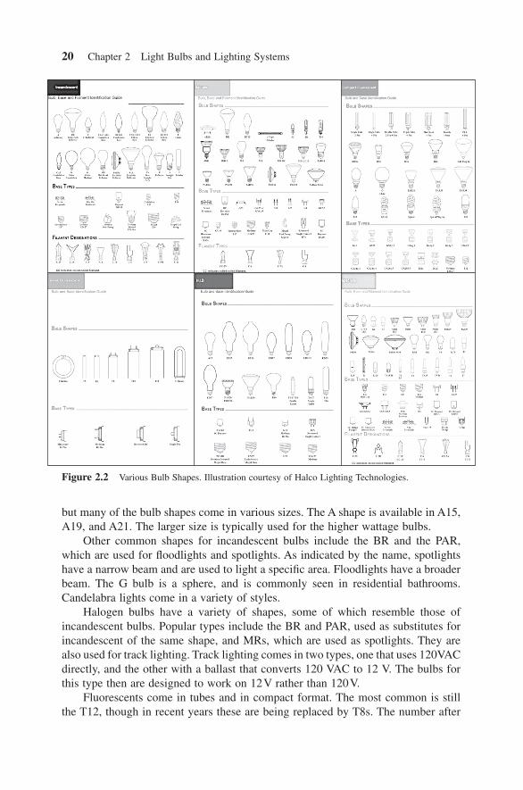
There are a surprising number of different bulb shapes available, as shown in Figure 2.2 . The most common type in the world is the A shape, the standard pear shape. And in the A shape, the A19 is by far the most common. The number 19 after A signifi es the diameter of the bulb in eighths of an inch (for the United States). Thus an A19 has a diameter of 19 8 2 3
8/ in in= . In the rest of the world, the number is the diameter in millimeters, so that a common size is A55. The fi gure doesn ’ t show it,
c02.indd 19c02.indd 19 2/10/2011 10:13:34 AM2/10/2011 10:13:34 AM
20 Chapter 2 Light Bulbs and Lighting Systems
but many of the bulb shapes come in various sizes. The A shape is available in A15, A19, and A21. The larger size is typically used for the higher wattage bulbs.
Other common shapes for incandescent bulbs include the BR and the PAR, which are used for fl oodlights and spotlights . As indicated by the name, spotlights have a narrow beam and are used to light a specifi c area. Floodlights have a broader beam. The G bulb is a sphere, and is commonly seen in residential bathrooms. Candelabra lights come in a variety of styles.
Halogen bulbs have a variety of shapes, some of which resemble those of incandescent bulbs. Popular types include the BR and PAR, used as substitutes for incandescent of the same shape, and MRs, which are used as spotlights. They are also used for track lighting. Track lighting comes in two types, one that uses 120VAC directly, and the other with a ballast that converts 120 VAC to 12 V. The bulbs for this type then are designed to work on 12 V rather than 120 V.
Fluorescents come in tubes and in compact format. The most common is still the T12, though in recent years these are being replaced by T8s. The number after
Figure 2.2 Various Bulb Shapes. Illustration courtesy of Halco Lighting Technologies.
c02.indd 20c02.indd 20 2/10/2011 7:11:01 PM2/10/2011 7:11:01 PM
Types of Bulbs 21
the “ T ” again refers to the diameter of the tube in eighths of an inch. A T12 has a diameter of 12/8 in = 1.5 in. The normal length of a fl uorescent tube is 4 ft, but there are also 8 - ft types used in very high ceilings, such as the high output (HO) and very high output (VHO) tubes. There are also circlines and U - tubes, seen in ceiling panels that are too small for the normal 4 - ft length of tube. CFLs are now most commonly seen in the spiral shape, but there are many multiple tube types available. (These are better referred to as “ biax ” and “ triax. ” ) CFLs are also being put inside a variety of incandescent bulb shapes, sometimes with their own letter designators.
Bulb Bases
In addition to the various types of bulbs, there are also a variety of base types, but most bulbs come in only one or two base types. The most popular bulb shape is the A19 (or A55). In the United States and European Union, this comes in a bulb base that is called the medium screw base, the E26 (or E27 in the E.U.). This is thus probably the most common bulb base. However, in the United Kingdom and Ireland, the A55 bulb comes in a bi - pin base. And of course, fl uorescent tubes also have two pins at each end.
In California, a pin base is used for government policy reasons. Under Title 24, new and remodeled houses are required to use energy - effi cient lighting. Energy - effi cient in practice means CFLs. But to prevent people from swapping out the CFL for an incandescent bulb, the fi xtures are required to be a special type needing a pin base rather than a medium screw base. Anecdote suggests the requirement is well - founded. We have repeatedly heard of people swapping out the entire light fi xture after the inspector has fi nished, to get rid of the hated CFL.
Specialty Bulbs
There are a huge variety of specialty bulbs. We call them specialty because they are not sold in billions, but they may still be sold in tens of millions. LEDs fall in this category for the moment. For example, cars use a variety of different lights: head-lights, taillights, panel lights (for the dashboard), dome lights (for overhead lighting). All of these types have been incandescent in the recent past, and presumably will be LED in the near future. Taillights on trucks and buses now are almost all LED - based. Buses and airplanes use a small fl uorescent tube for interior lighting. And at least in the United States, 80% of all traffi c lights have converted from incandescent to LED. There ’ s actually been a problem reported with LED traffi c lights. They generate so much less heat than the old incandescent bulbs that they don ’ t melt the snow off in the winter. We ’ ve also heard complaints from people in the Northwest Territories of Canada that without incandescent lighting, the house was not as warm in the winter.
Emergency exit signs are now nearly 100% LEDs. Here the reason is purely economic. An emergency sign is required to run for 90 minutes in the event of a power outage. This determines the size of the battery, the most expensive
c02.indd 21c02.indd 21 2/10/2011 10:13:34 AM2/10/2011 10:13:34 AM
22 Chapter 2 Light Bulbs and Lighting Systems
component. So in this case a change to a light source that uses less energy saves money for the manufacturer.
Similar energy - saving considerations are behind a change from incandescent lighting in refrigerator cases to LEDs. The heat generated by the incandescent is not only wasted energy; it also has to be removed by the cooling unit! There is thus a double hit on the cost.
The desire for energy saving in computers and cell phones has also led to the use of LEDs for backlighting, even though at fi rst it wasn ’ t entirely economical. The reason in both cases was the desire to save the battery energy. For the same reason, fl ashlights now almost universally use LEDs. Here the reason is not only to save the battery, but also to increase the light output without overheating. Televisions are also headed in the same direction, although for general energy - saving reasons.
Almost everything named in this section has been about conversion to LEDs . One area that may not change is oven lights. Since ovens run up to 550 ° F (300 ° C), incandescent bulbs seem like a natural choice. They are not affected by heat, but semiconductors are. They may never be changed; there are still vacuum tubes used in some specialty areas.
HISTORY OF LIGHTING
Edison made the fi rst practical incandescent light bulb in the 1880s. Fluorescent tubes became popular in the 1950s. LEDs are just starting to become popular in the 2000s. What will the future bring?
Jeff Tsao , a Principal Member of the Technical Staff at Sandia National Labs, researched this question, which deserves to be more widely known (Tsao, 2009 ). He looked at worldwide consumption of artifi cial light over the last several hundred years, covering candles, kerosene lamps, gas lighting, incandescent bulbs and fl uorescent tubes. Obviously, much of the older data can ’ t be that accurate. But when plotted on a log scale, these inaccuracies aren ’ t that signifi cant. What was clear is that over the entire time period, the world has spent an approximately constant percentage of its GDP on lighting, 0.72%.
Assuming this continues into the future, this has a surprising consequence. One of these is that as lighting becomes more effi cient, total light used will increase. The introduction of LED lighting at, say, twice the effi cacy of fl uorescent lighting will mean that twice as much light is used, not that half the energy is saved. Energy is saved according to the model only if GDP decreases or the cost of electricity decreases.
This conclusion seems to fi t with what is actually happening in the world today. Governments reasoned about energy - effi cient lighting as follows. “ If you replace all of the 60 W incandescent bulbs with 15 W CFLs, the energy saved will be 45 W times the number of bulbs. ” But these energy savings have not been entirely realized. Anecdotally , people report that they want brighter lights, not lower energy consump-tion. The reasoning apparently goes like this: “ My closet was lit by a 40 W incan-
c02.indd 22c02.indd 22 2/10/2011 10:13:34 AM2/10/2011 10:13:34 AM
Lighting Systems 23
descent. With a CFL I get the same light for only 10 W. But my closet was always dim. I can upgrade to a 15 W CFL and still save energy! ”
Our expectation is this. As Haitz ’ s law continues, the exponential increase in effi cacy and decrease in cost will drive almost all lighting to convert to LED. This will be translated into a huge increase in the total amount of light used in the world. As the ultimate physical limits on effi cacy are reached, the amount of light used in the world will stabilize. Increases will thereafter be small, driven by ordinary increases in GDP and population.
GOVERNMENTS
Governments worldwide have become interested in regulating lighting. A simple calculation shows why. Twenty billion light bulbs times 60 W each times 4 hours a day equals over 1 trillion KWH a year! This is about 20% of all electricity used in the world. This huge energy consumption has serious consequences for the economy, for national security, and for the environment.
Such considerations have led to numerous government regulations. We ’ ve already mentioned Title 24 in California. Even more draconian measures are being implemented worldwide. Many governments have, or shortly will, ban the sale of incandescent bulbs entirely.
Why not just let the economics speak for itself, and let people switch to energy - effi cient lighting to save money? The problem is that individually the change doesn ’ t make a lot of sense. Consider changing a 60 W incandescent bulb to a 15 W CFL (or a 10 W LED bulb). That saves 45 W. The bulb is on an average of 4 hours a day. That ’ s 180 Wh a day. With electricity costing 12 cents/kWh, that switch to energy - effi cient lighting has saved 2 cents! While this adds up to $7.88 for the whole year, in the developed countries such an amount may not be considered worth the time spent — and many people feel it is not worthwhile going to a bad - looking light source for this amount of savings.
LIGHTING SYSTEMS
So far we ’ ve discussed light bulbs and their usage. But bulbs aren ’ t used by them-selves; they need infrastructure to work, such as electricity and ballasts. This comes under the heading of lighting systems. Details about the electricity supply will be discussed in Chapter 8 . As for ballasts, corresponding to the large number of differ-ent bulbs there are a large number of ways to run them. In this section, we ’ ll consider ballasts for fl uorescents and then for LEDs.
As we ’ ve indicated, fl uorescent tubes have special voltage and current require-ments that mean they can ’ t be powered directly by the AC line. Instead, the AC line powers a special electronic circuit called a ballast , which in turn powers the fl uo-rescent lamp. Fluorescent ballasts come in two varieties, instant start and rapid start. The difference lies in how the fi laments are treated. You ’ ll recall that a fi lament is used to provide electrons to the plasma arc. In a rapid start ballast, the fi laments are
c02.indd 23c02.indd 23 2/10/2011 10:13:34 AM2/10/2011 10:13:34 AM
24 Chapter 2 Light Bulbs and Lighting Systems
preheated, that is, they have power applied to them and are warmed up to about 1100 K before they have to start emitting electrons. This has the benefi t of making the fi laments last a long time, but the downside of requiring extra power. With an instant start ballast, the fi laments are not preheated. This saves power, but makes fi lament life, and thus tube life, much shorter.
In principle, you could get the best of both worlds by preheating the fi laments, and then turning them off after arc ignition. But this isn ’ t common, probably because of the cost of the extra circuitry to do this. Something similar is done, however, with dimming ballasts. (Normal fl uorescent ballasts don ’ t work with dimmers; you have to buy a special type that does.) As the tube is dimmed , the plasma arc heating the fi lament heats it less and less. To maintain fi lament temperature, which is what keeps them running for a long life, fi lament power is increased in a dimming ballast inversely proportionally to the degree of dimming.
One other differentiation among fl uorescent ballasts is that some are magnetic , while others are electronic . Magnetic ballasts are basically a large piece of iron in the form of a transformer, with a big capacitor on the output to limit current into the fl uorescent tube. They of course run at line frequency, which is why they are big and heavy. Electronic ballasts are switch - mode power supplies. They are much lighter, but have the same mechanical size as magnetic ballasts for backward com-patibility. They tend to run above 20 KHz , for reasons of size and to avoid audio noise, as well as to take advantage of the small gain in effi cacy of fl uorescent tubes above 10 KHz.
Most LEDs are similar to fl uorescent tubes in not being directly compatible with the AC line. (Some are, and this may well be the future of LED systems.) They also require a ballast to convert AC power to the constant current that is best for LEDs. Chapter 8 in this book covers design of these ballasts. It is to be noted that some people reserve the word “ ballast ” for fl uorescent tube electronics, and prefer the word “ driver ” for LEDs.
We have the AC power line, the ballast, the lamp; surely that ’ s everything in the lighting system? No, there ’ s also the physical environment the lamp operates in. It too infl uences light production and effi cacy. Since incandescent bulbs operate at thousands of degrees, they are relatively insensitive to environmental temperature; not so fl uorescent and LED bulbs. Fluorescent systems require a longer time to start when it ’ s cold. The fl uorescent tube in your garage has trouble starting in winter for this reason. There are special fl uorescent ballasts designed for cold weather. Conversely, CFLs can have problems with high ambient temperature. Placed into a ceiling can, the temperature can rise enough to cause the CFL to fail, sometimes catastrophically. Since the actual temperature in the can depends on many factors (how much power is being dissipated, whether the can is insulated or enclosed, what the ambient temperature is), in general CFLs are not recommended for can usage.
LEDs lights have similar problems. Although they are not as sensitive to cold, their ballasts may be. And if they get hot, their light output decreases and their lifetime also goes down. In an insulated enclosed can, they can get hot enough to fail. This can be particularly true if you design an LED system to have constant light output. As the temperature increases, their effi cacy decreases. Thus you put more
c02.indd 24c02.indd 24 2/10/2011 10:13:34 AM2/10/2011 10:13:34 AM
Lighting Systems 25
power into the LEDs to compensate for their decrease in effi cacy. But this causes the temperature to rise even more.
Another environmental factor is the fi xture into which the bulb is placed. This can dramatically infl uence the light output of the lighting system. As an extreme example, consider a fl uorescent tube mounted into a black fi xture . Since half of the light from the tube goes upward, this half will be absorbed. The actual light output from the system will be only half that generated by the tube, thus also reducing the effective effi cacy by half. While tube fi xtures are not usually black, they can lose as much as 30% of the light output. LEDs can potentially avoid this loss because they are not omnidirectional.
One more environmental factor almost never discussed is dust . There is some residual voltage present on fl uorescent tubes that tends to attract dust. (The same is more noticeable on your laptop computer screen.) Of course, no one dusts their lamps. Over years of operation, this dust can cut the actual light output from the lighting system by 30%. Whether LED bulbs also suffer this problem, or can claim additional effi cacy over fl uorescent lighting systems, remains to be seen.
c02.indd 25c02.indd 25 2/10/2011 10:13:34 AM2/10/2011 10:13:34 AM