ppt16/22 bhc & ppt16bmcy
TRANSCRIPT

PPT16/22 BHC & PPT16BMCYOwner Installationmanual (SD638152 issue 4)

Thank you for choosing Calorex.
Your Calorex heat pump has been specially designed for pool heating using high quality components that are carefully chosen to provide maximum efficiency and reliability. This manual will help you to get the best out of your heat pump and advise you on how to maintain it.
2 SD638152 ISSUE 4
PPT16/22 BHC & PPT16BMCY OWNER INSTALLATION MANUAL

i3.0
i9.0 PPT8 = 20APPT12 = 25APPT16 = 30APPT22 = 42A
1Ø
PPT8 = 10APPT12 = 10APPT16 = 15APPT22 = 20A
3Ø
H.R.C./ MCB (Type C)
i4.3
112
23
4567
89
1011
i2.3
i3.1
pH CaCO3
i4.1i11.0
QUICK START GUIDE
QUICK START GUIDE
3SD6381652 ISSUE 4

HEALTH AND SAFETY WARNING
As the dehumidifier embodies electrical and rotational equipment, ONLY competent persons should carry out any work on this type of machine.
(SEE GUARANTEE)
QUICK START GUIDE .................................................................3
HEATH AND SAFETY WARNING ..............................................5
1.0 INTRODUCTION ...................................................................5
1.1 FUNCTION .............................................................................6
2.0 INSTALLATION ....................................................................7
2.1 ACCESSORIES ......................................................................7
2.2 SITING ....................................................................................7
2.3 AIR FLOW ..............................................................................8
3.0 PLUMBING ............................................................................9
3.1 RECOMMENDED PLUMBING SCHEMATIC ................... 10
3.2 DETERMINING WATER FLOW ......................................... 11
4.0 ELECTROLYTIC CORROSION IN SWIMMING POOLS .. 12
4.1 ELECTRICAL (MACHINE WIRING AND SUPPLY).......... 13
4.2 LOCATION OF MAINS INPUT AND EXTERNAL INTERLOCK TERMINALS .............................................................................. 14
4.3 ENERGY MANAGEMENT CONTROLLER ....................... 15
5.0 DIGITAL THERMOSTAT .................................................... 16
5.1 CONSOLE LAMPS ............................................................. 16
6.0 CIRCUIT DIAGRAMS ......................................................... 17
7.0 REGULAR PLANNED MAINTENANCE ........................... 19
8.0 HEAT PUMP MALFUNCTION ........................................... 20
8.1 USER CHECK LIST ............................................................ 20
9.0 DATASHEETS ..................................................................... 21
10.0 INSTALLATION DRAWING ............................................. 23
11.0 WINTERISATION PROCEDURE ..................................... 24
11.1 START UP PROCEDURE AFTER WINTERISATION ..... 24
12.0 WARRANTY CONDITIONS ............................................. 25
13.0 MACHINE RECORD LOG ................................................ 26
Contents
4 SD638152 ISSUE 4
PPT16/22 BHC & PPT16BMCY OWNER INSTALLATION MANUAL

Calorex ‘Propac’ HC air to water heat pumps are for areas of the world where the ambient temperature can vary from 7ºC to 50ºC. The pool water is heated when the ambient temperature is low and cooled when the ambient temperature is high, enabling the user to enjoy the pool throughout the year. The units are designed for swimming pools, using R134a as a refrigerant and are ideally suited for operation in a tough climate.
Calorex ‘Propac’ BMC air to water heat pump is designed to operate in temperatures from -15ºC to 40ºC and is suitable for heating and chilling swimming pools.
The water heat exchanger is a full flow type, manufactured from titanium tube, which is a highly corrosion resistant material. The heat pumps are suitable for use in fresh water and salt water pools. PPT8/12 heat pumps are fitted with rotary compressors and PPT16/22 heat pumps are fitted with scroll compressors. Both types of compressor are known for quiet running. A 6 minute compressor start delay timer is incorporated for compressor protection. With these features the heat pump is designed to have a long, trouble free life.
All units have integral safety devices to protect the heat pump from internal and external faults. Indicator lamps indicate operating mode. An adjustable digital thermostat controls water temperature.
Dantherm Ltd is an ISO9001:2000 certified company.
All Calorex heat pumps are CE approved
1.0 INTRODUCTION
HEALTH AND SAFETY WARNING
This appliance can be used by children from eight years and above and persons with reduced physical, sensory or mental capabilities or lack of experience and knowledge if they have been
given supervision or instruction concerning the use of the appliance in a safe way and understand the hazards involved. Children should not play with the appliance. Cleaning and maintenance shall
not be made by children without supervision.
Disconnect from the mains supply and wait three minutes before removing panels and commencing work on this machine.HEATH AND SAFETY WARNING
5SD6381652 ISSUE 4

1.1 FUNCTION
The Calorex Swimming pool heat pump provides thermodynamic heating by means of a vapour compression cycle, (similar to that employed in a
conventional refrigerator), in addition to acting as an active solar collector.
COEFFICIENT OF PERFORMANCE
The efficiency of a Heat Pump is usually called its ‘Coefficient of Performance’ - (C.O.P.) which is simply a ratio of heat output to energy input, both being expressed in kW. Thus a Heat Pump absorbing 1 kW of electricity, collecting
4kW of energy from the air, and delivering 5kW of heat to the pool water is said to have a C.O.P. of 5:1.
This ratio will vary according to the temperature of the water and the ambient air.
THE HEAT PUMP CYCLE
1. THE EVAPORATOR collects the heat from the outside ambient air, pre-heated by the sun. In the Calorex swimming pool heat pumps, high volumes of outside air are drawn into the unit by the fan expelled through the evaporator fins. The evaporator has liquid refrigerant passing through it which is at a considerably lower temperature than the ambient air.
Therefore the air gives up its heat to the refrigerant which then vaporises.This preheated vapour now travels to -
3. THE CONDENSER where it is surrounded by the pool water. The heat is given up to the cooler pool water and the now cooler refrigerant returns to its former liquid state but still under high pressure from the compressor. This pressure is released by passing liquid through-
1. THE COMPRESSOR where it is compressed and upgraded to a much higher temperature. The hot vapour now enters-
4. THE EXPANSION DEVICE and from there, now at normal pressure, it is returned to the evaporator and the cycle starts again.
NOTE THAT WHEN A HEAT PUMP IS CHILLING THE CYCLE IS REVERSED
POOLWATER OUT
POOLWATER IN
HOT GAS
HEAT EXCHANGER
CONDENSED REFRIGERANT
HIGH PRESSURE SIDE
COMPRESSOR
EXPANSION VALVE
LOW PRESSURE SIDE
COOL LIQUID REFRIGERANT
AMBIENT AIR
COOL GAS
EVAPORATOR
1
2
3
4
6 SD638152 ISSUE 4
PPT16/22 BHC & PPT16BMCY OWNER INSTALLATION MANUAL

2.0 INSTALLATION
a) Ensure heat pump on site is as ordered, i.e. model, electrical supply and factory fitted options.
b) Inspect unit for damage, in particular inspect the evaporator (finned side) to ensure that it is undamaged. (Minor indentations in the fins do not affect performance). If severely damaged, endorse delivery note in presence of the driver and send a recorded delivery letter to transport company giving details. Protect unit if installation is delayed.
2.1 ACCESSORIES
The heat pump is supplied with accessories which aid installation. On delivery the accessories are in a plastic bag in the heat pump electric box. (See section 4.2 for lid removal).
These accessories are as follows:
4 x rubber feet - Fit these under the metal feet of the heat pump to help reduce the effects of vibration.
2 x 50mm female connectors - On delivery the heat pump has 1½” sockets attached to the water connections for fitting 1 ½” plastic pipes. If 50mm pipework is preferred undo the threaded couplings on the water in/out connection points and carefully remove the 1 ½” sockets. Then fit the 50mm sockets in their place and refit the threaded couplings. The heat pump can then be fitted with 50mm plastic pipe.
2 x Condensate drain piece - Condensate drain pieces are supplied suitable for ¾” or 20mm pipe. Use whichever piece fits the drain pipe required. Glue the relevant piece to the driptray outlet and then fit then condensate drain piping.
2.2 SITING
a) Provide a firm level base capable of supporting operational weight of unit; spread load if mounted on timber floor.
b) Ensure water cannot collect under unit, it is recommend that units are installed on plinths 100mm above finished floor level. This also aids condensate drainage.
c) Allow adequate clearance to service panels on unit; recommend 500mm minimum.
d) All Calorex heat pumps are by design as quiet as is practical, however due consideration should be given to siting the heat pump in order to minimise the noise coming from the machine, for example by positioning the machine so that the inlet/outlets are parallel to occupied premises.
e) Ensure loose debris such as leaves, grass cuttings, etc will not block air inlet grilles.
f) Consider protection from extreme weather conditions if installed externally, i.e. lean-to-cover or building.
7SD6381652 ISSUE 4

2.3 AIR FLOW
IMPORTANT
If multiple units are installed in an enclosed area then the inlet free areas required for each unit can be added together to form one inlet aperture. BUT discharge from each unit must be kept separate and must not be incorporated into one common duct system.
Table 1
Model Minimum Free Area m2
Inlet Discharge
PPT16 0.322 0.173
PPT22 0.322 0.173
Due consideration must be given to air flow i.e. do not obstruct inlet or outlet and ensure discharge to air cannot recirculate to inlet. (See below).
Required Free Areas to provide air flow to and from heat pumps when installed in an enclosed area or where required to pass air through a wall etc.
Free areas is the available area through which air can pass through a grille or louvres.
> 50 cm
SWIMMING POOL/SPA
CALOREXPLANT ROOM
CALOREX
CALOREX
CALOREX
WALL
CALO
REX
SUITABLE OPENING
POSSIBLE POSITIONS OF A CALOREX HEAT PUMP
WALL
SUITABLE OPENING
8 SD638152 ISSUE 4
PPT16/22 BHC & PPT16BMCY OWNER INSTALLATION MANUAL

3.0 PLUMBING
a) Calorex Heat Pumps have water inlet/outlet connections as follows:
All models have fittings which enable the heat pump to be connected to either 1½” or 50mm pipe work.
b) The heat pump is supplied with bungs fitted in the water connection fittings These need to be removed before the heat pump is installed. (See section 3.2).
c) The Calorex Heat Pump must be connected after the filter in the return pipe to the pool. If an existing heater is being retained, then the Calorex Heat Pump should be connected between the filter and the other heater. (See section 3.1).
d) Suitable breakable couplings should be installed local to the heat pump.
e) If the heat pump is installed at a lower level than the pool then isolation valves should be fitted.
f) A drain valve or plug should be fitted to the lower pipe to facilitate drain down in the winter period.
g) Connections on all models are by 1½” or 50mm Female fittings. The water in/water out pipes need to be glued into these connections using a suitable adhesive.
h) The condensate drain at the base of the unit collects condensation from the evaporator fins. This should run away to waste via ¾” domestic waste piping. It is therefore necessary to ensure that the Calorex Heat Pump is placed on a level plinth so that the condensate water can run away with adequate fall to waste i.e. ½” per foot minimum and must incorporate a “u” trap as to not overflow the edges of the drip tray inside the heat pump. See below.
) When the pipework installation is complete the pool pump should be switched on and the system tested for leaks. Also check the filter gauge to see that there is not an excessive increase in back pressure. If everything is then working normally the water circulating system is ready for use.
j) Water circuit to and from the unit is to be capable of maintaining within specified limits the rate of flow required by the heat pump. (See section 9).
k) All pipework must be adequately supported with allowance expansion/contraction especially with plastic pipework.
l) It is recommended that when installing water systems the last connections to be made in the system should be breakable connections to avoid any stresses on the unit connections.
IMPORTANT
1. All Pool Purifying Devices and Chemical Injection Systems to be fitted down stream of the heat pump (see section 3.1) unless installation is as per filter dosing. This includes the practice of dosing chemicals direct into skimmer basket, which results in concentrated corrosive liquids passing over vulnerable metal components.
2. Water quality must be maintained as follows:
3. Maximum pressure of water in heat pump circuit should not exceed 3.5bar for PPT16/22 (50 psi).
This type ofinstallationshould be avoided Incorrect drainage
for condensateCORRECT DRAINAGEFOR CONDENSATE Elbow
'U' trap
Adequate fall
Acidity pH pH 7.2 - 7.8
Total Alkalinity, as CaCO3 ppm 80 - 120
Total Hardness, as CaCO3 ppm 150 - 250
Total Dissolved Solids ppm 1000 Max
Maximum Salt Content ppm 35000 Max
Free Chlorine Range ppm 1 - 2 Domestic
Free Chlorine Range ppm 3 - 6 Commercial
Superchlorination max 30ppm for 24 hrs
Bromine ppm 2 - 5
Baquacil ppm 25 - 50
Ozone ppm 0.9 Max
Maximum Copper Content ppm 1
Aquamatic Ionic Purifier ppm 2 Max
9SD6381652 ISSUE 4

3.1 RECOMMENDED PLUMBING SCHEMATIC
KEY ISOLATION VALVE BREAKABLE COUPLING
NON RETURN VALVE THREE WAY VALVE
NON RETURNVALVE
CHEMICAL DOSING SANITISER OR
DEVICE, IF FITTED
AUX HEATER IF FITTED
FILTER PUMP
TO WASTE FORWINTERISINGDRAIN DOWN
ANTI RETURN LOOPTO BE INCORPORATED,
MINIMUM HEIGHT100mm ABOVE HEAT PUMP
OUTLET PORT(IF SANITISER FITTED)
100m
m
CONDENSATE WATERTO WASTE
SPARE PORT FORWINTERISING
FLUSHINGCONNECTION
TO WASTE CALOREXHEAT PUMP
POOL
BYPASS VALVE(NORMALLY
CLOSED)
10 SD638152 ISSUE 4
PPT16/22 BHC & PPT16BMCY OWNER INSTALLATION MANUAL
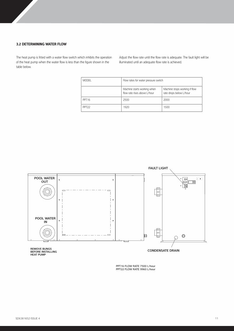
3.2 DETERMINING WATER FLOW
The heat pump is fitted with a water flow switch which inhibits the operation of the heat pump when the water flow is less than the figure shown in the table below.
Adjust the flow rate until the flow rate is adequate. The fault light will be illuminated until an adequate flow rate is achieved.
MODEL Flow rates for water pressure switch
Machine starts working when flow rate rises above L/hour
Machine stops working if flow rate drops below L/hour
PPT16 2500 2000
PPT22 1920 1500
PPT16 FLOW RATE 7500 L/hourPPT22 FLOW RATE 9960 L/hour
REMOVE BUNGS BEFORE INSTALLING HEAT PUMP
POOL WATER IN
POOL WATER OUT
CONDENSATE DRAIN
FAULT LIGHT
11SD6381652 ISSUE 4

4.0 ELECTROLYTIC CORROSION IN SWIMMING POOLS
Electrolytic corrosion will occur when dissimilar metals that are in contact with each other create a potential difference between themselves. Sometimes separated by a conductive substance known as an electrolyte, the dissimilar metals will create a small voltage (potential difference) that allows the ions of one material to pass to the other.
Just like a battery, ions will pass from the most positive material to the more negative material.
Anything more than 0.3 volts can cause the most positive material to degrade.
A swimming pool with its associated equipment can create this effect. The pool water being an ideal electrolyte and components of the filtration circuit, heating system, steps, lights etc providing the dissimilar metals needed to complete the circuit.
Whilst these small voltages are rarely a safety threat, they can create premature failure through corrosion. Not dissimilar to corrosion through oxidation, electrolytic corrosion can cause complete failure of a metallic material in a very short period of time.
In order to prevent this type of corrosion all metallic components in contact with swimming pool water should be bonded together using 10mm² bonding cable. This includes non-electrical items such as metal filters, pump strainer boxes, heat exchangers, steps and handrails. It is highly recommended that bonding be retrofitted to existing pools, which may not be protected by this system.
12 SD638152 ISSUE 4
PPT16/22 BHC & PPT16BMCY OWNER INSTALLATION MANUAL

4.1 ELECTRICAL (MACHINE WIRING AND SUPPLY)
All electrical work to be carried out in accordance with l.E.E. standards, latest issue, or local codes of practice as applicable.
The machine should be installed in line with EMC2004/108/EC.
Protected supply to incorporate fuses or motor type circuit breakers (Type C) to specified rating, (see Data Sheet). H.R.C. fuses are recommended. An isolator which disconnects all poles must be fitted within 2m and in sight of machine.†
All units must be correctly earthed-grounded. An earth leakage trip of the Current operating type (30mA) is recommended to be fitted to all pool electrics.
INCONSISTENT ELECTRICAL SUPPLY
The following limits of operation must not be exceeded if Dantherm Ltd. machines are to be guaranteed either in performance or warranty terms:
This voltage must be made available at the heat pump while running.
† Note the Isolator must have a minimum of 3mm air gap when turned off.
NOTE: The heat pumps are fitted with a phase protection relay and will not run if the phases are not connected in the correct order (phase sequence) or if the supply voltage is 15% less than the nominal voltage (415V for 3N~ 50Hz). The lamp on the phase rotation relay (situated in the electric box) is illuminated when the phases are correctly connected and the voltage is sufficient.
IMPORTANT
The user should be made aware that THE WHOLE installation should be isolated when working on ANY PART.
MINIMUM MAXIMUM
Voltage three phase 360V 440V
Frequency Hz 47.5 52.5
13SD6381652 ISSUE 4

4.2 LOCATION OF MAINS INPUT AND EXTERNAL INTERLOCK TERMINALS
THREE PHASE 400V ~3N 50Hz
MAKE MAINS IN EARTH CONNECTION HERE
CABLE ENTRY POINT
ELEC. BOX EARTH STUD
CONTROLLERMANAGEMENTENERGY
INTERLOCK
SWITCHFLOWWATER
6
5
N
L3
L2
L1
10
8
7
9
FAN L
COIL
VALVESOLENOID
COILVALVEREVERSING
FAN N
15
16
18
20
19
17
12
11
14
13
CONTROLLERMANAGEMENTENERGY
INTERLOCK
SWITCHFLOWWATER
N
L3
L2
L1
6
5
10
8
7
9
MAINS IN
LIFT COVER OFF
ELECTRIC BOX
STAT
LOOSEN CAPTIVE SCREWS (2)AT THIS END
BRACKET RIVETTED TO COVER AT THIS END FITS THROUGH
SLOT IN PANEL
TO REMOVE INNER COVER FROM TOP OF
ELECTRIC BOX UNDO THE 2 SCREWS AND SLIDE
BACKWARDS TO DISENGAGE TABS.CHECK THAT THE
CONNECTORS IN THE BACK OF THE DIGITAL
THERMOSTAT ARE SECURE.(SEE SECTION 5.1)
14 SD638152 ISSUE 4
PPT16/22 BHC & PPT16BMCY OWNER INSTALLATION MANUAL

4.3 ENERGY MANAGEMENT CONTROLLER
The use of a Calorex Energy management controller can enable great savings in the running costs of your pool heating system by allowing the circulating pump to run only at times preferred by the customer, for example during the Economy 7 period.
A pair of terminals (9 and 10 in the heat pump electric box) are connected between the heat pump and the Energy management controller.
CUSTOMERS EXTERNAL PUMP/FILTER TIME CLOCK
N
L
CALOREX HEAT PUMP. EXTERNAL COMPONENTS TO
BE WIRED TO TERMINAL BLOCK LOCATED INSIDE MACHINE ELECTRIC BOX.
9
10
POOL PUMP STARTER
MAX RATING 3A ½ HP AT 250V
15SD6381652 ISSUE 4

5.0 DIGITAL THERMOSTAT
An adjustable 2 stage digital thermostat controls and maintains the water temperature.
Press the P key to display required temperature. To alter required temperature press the up or down keys. Press P to store the desired setting. After 5 seconds the display reverts to actual water temperature.down keys. Press P to store the desired setting. After 5 seconds the display reverts to actual water temperature.
5.1 CONSOLE LAMPS
RED MAINS LAMP
MAINS SWITCH
AMBER FAULT LAMP
CLEAR DEFROST/CHILL LIMIT LAMP
RED
IO
AMBER
CLEAR
!
NOT USED
SET POINT AND PARAMETER PROGRAMMING BUTTON
INCREASE VALUES
DECREASE VALUESOut
U
P
TLZ 11
AL
AMBER
RED
CLEAR
IO
CHILL LIMIT RESET.PRESS RED BUTTON TO RESET, USE A SCREW DRIVER OR SIMILAR TOOL.
16 SD638152 ISSUE 4
PPT16/22 BHC & PPT16BMCY OWNER INSTALLATION MANUAL

6.0 CIRCUIT DIAGRAMSPPT16/22 BHC THREE PHASE 400V~3N 50HZ
(CHILL LIMIT FAULT)DEFROST LIGHT
U1 U2
TERM'LBLOCK11
TERM'LBLOCK 12
8 (N
/O)
(CO
M) 7
(CO
M) 6
4 (N
/C)
12
1011
2SENSOR
POOL STAT
MAINS LIGHT
INTERLOCKTERMINALS
SMART CLOCK FEED TERMINALS
NEUTRAL
SOFT START THERMAL OVERLOAD & FAULT LIGHT
L3
CRANKCASE
5
6
9
10
N
L
FAN
HEATER
DELAY TIMER
FAULT LIGHT
L2PHASE ROTATION RELAY
L3L2L1
CONTROL FUSES
3A
3A
FAN FUSE
L1
12 (N
/C)
11 (COM)
MAINS SWITCH
14 (N
/O)
1
(N/O) 3
C (COM)H (N/C)(N/O) L
C (COM)H (N/O)(N/C) LLP SWITCH
BREAKS TO 'H' ON PRESSURE FALLING
A
B
6 (N
/O)
3 (N
/C)
(CO
M) 9
4 (N
/O)
1 (N
/C)
(CO
M) 7
RELAY 2
POOL/WATER2 STAGE STAT
(SHOWN IN HEAT MODE)
A
BRELAY 1
1 (N
/C)
4 (N
/O)
7 (C
OM
)
REVERSING VALVE
C (COM)
H (N/O)L
(N/C
)
CHILL LIMIT SWITCHBREAKS TO 'H' ON FALLING PRESSURE OR TEMPERATURE
C (COM)H (N/O)(N/C) LDEFROST
STAT
SHUT OFF VALVE
5
3
1
6 (N/O)
4 (N/O)
2 (N/O)
CONTACTOR
A2 A1
SOFT START
U
V
WCOMPRESSOR
7
8
13
14
FLOW SWITCH
3A
MODEL
PPT16BHC 3A
FUSE RATINGS FAN FUSE CONTROL FUSES
3APPT22BHC 3A
HP SWITCHBREAKS TO 'L' ON PRESSURE RISING
3 (N
/C)
6 (N
/O)
9 (
COM
)
17SD6381652 ISSUE 4

PPT16 BMCY THREE PHASE 400V~3N 50HZ
8 (N
/O)
(CO
M) 7
(CO
M) 6
4 (N
/C)
1
210
11
2SENSOR
POOL STAT
MAINS LIGHT
HP SWITCHBREAKS TO 'L' ON
INTERLOCKTERMINALS
SMART CLOCK
NEUTRAL
SOFT STARTTHERMALOVERLOAD& FAULTLIGHT
L3
CRANKCASE
FEED TERMINALS
5
6
9
10
N
L
FAN
HEATER
DELAY TIMER
FAULTLIGHT
L2PHASE ROTATION RELAY
L3L2L1
CONTROL FUSES
3A
3AFAN FUSE
PRESSURE RISING
L1
12 (N
/C)
11 (COM)
MAINS SWITCH
14 (N
/O)
1
(N/O) 3
C (COM)H (N/C)(N/O) L
C (COM)H (N/O)(N/C) LLP SWITCH
BREAKS TO 'H' ONPRESSURE FALLING
A
B
6 (N
/O)
3 (N
/C)
(CO
M) 9
5 (N
/O)
2 (N
/C)
(CO
M) 8
RELAY 2
POOL/WATER2 STAGE STAT
(SHOWN IN HEAT MODE)
A
B
1 (N
/C)
4 (N
/O)
7
3 6
9
REVERSING VALVE
C (COM)H (N/O)
L (N
/C)
CHILL LIMIT SWITCH BREAKSTO 'H' ON PRESSURE/TEMPERATURE FALLING
5
3
1
6 (N/O)
4 (N/O)
2 (N/O)CONTACTOR
A2 A1
SOFT START
U
V
W
COMPRESSOR
(CHILL LIMIT FAULT)DEFROST LIGHT
U1 U2
TERMBLK 11
TERMBLK 12
4 (N
/O)
1 (N
/C)
(CO
M) 7
2 (N
/C)
5 (N
/O)
8
53 54 (N/O)
21 22 (N/C)
6364
(N/O
)
12
34
DEF
ROST
STA
T
7
8
13
14
FLOW SWITCH
7 1 (N/C)
RELAY 3
NEUTRAL AB
6 9RELAY 3
RELAY 1
FUSE RATINGS
3A
MODEL
PPT16BMCY 3A
FAN FUSE CONTROL FUSES
18 SD638152 ISSUE 4
PPT16/22 BHC & PPT16BMCY OWNER INSTALLATION MANUAL

7.0 REGULAR PLANNED MAINTENANCEOperations to be carried out during a regular planned maintenance visit are as follows:
1) Clean the evaporator. (This action may be required more frequently than regular servicing).
2) Check operation of fan and compressor.
3) Check capacitor tolerances-where fitted.
4) Check condition of all heat exchangers/evaporators.
5) Check refrigeration system parameters.
6) Check operation of control valves.
7) Check for water leaks.
8) Check driptray and internal drain lines for blockages and flush through if necessary.
9) Check operation of controls and calibrate if necessary.
10) Check operation of interlocks in use.
11) Final check of overall operation of unit
12) Indicate on Service report any faults found or causes for concern.
13) Recommended servicing frequency: one visit per year.
19SD6381652 ISSUE 4

8.0 HEAT PUMP MALFUNCTION
WARNING: Isolate heat pump electrically before entering heat pump or removing panels.
The user check list should be carried out before initiating a service call.
Do not attempt to interfere with any internal control settings as these have been factory calibrated and sealed.
Any sign of abnormal operation such as water dripping should be reported immediately to the installer.
If in doubt or if advice is required contact the Dantherm Group UK Service Department.
Telephone +44(0)1621 856 6118.1 USER CHECK LIST
Errors associated with the digital thermostat
LAMP ACTIONUNIT DOES NOT OPERATE
MAINS RED OFF
Check mains supply - external fuses - isolatorFAULT AMBER OFF
DEFROST/CHILL LIMIT CLEAR OFF
MAINS RED ONCheck unit ON/OFF.
FAULT AMBER OFF
DEFROST/CHILL LIMIT CLEAR OFF
Check thermostat is calling for heating or cooling. Wait 6 minutes, fan and compressor should run. If not, check any external equipment in Interlock circuit is not preventing the machine from starting. Check internal control fuses.
MAINS RED ON Check water and air flows are not restricted.FAULT AMBER ON Check thermal cut out on Soft Start if fitted.
DEFROST/CHILL LIMIT CLEAR OFF Check flow rate is adequate. Check Chill limit cut out switch and reset. Check water pump etc. to restore
water flow through machine.
LAMP FAN ON COMPRESSOR OFFMAINS RED ON Unit on defrost (heating mode) check air temperature is not below 7°C.
(-15ºC for a BMCY). Check chill limit cut out switch and reset.
FAULT AMBER OFF
DEFROST/CHILL LIMIT
CLEAR ON Unit off on chill limit (cooling mode).
LAMP UNIT OPERATES INTERMITTENTLY
MAINS RED ON Check water and air flows are not restricted
FAULT AMBER ON/OFF and that electrical supply is adequate.
DEFROST/CHILL LIMIT
CLEAR OFF
SYMBOL DESCRIPTION LAMP ON ACTION
E1-E1/E2-E2 Probe error Probe interrupted, short circuit or outside range. Check connection between probes and thermostat.
EPr Probe error Internal EEPROM memory error. Switch off heat pump at mains supply for five minutes then switch back on. If fault persists contact installer.
20 SD638152 ISSUE 4
PPT16/22 BHC & PPT16BMCY OWNER INSTALLATION MANUAL

NOTES1) Weight and dimensions nett. * Dimensions include water in/out stubs and mains in cable gland.2) Performance design limitations: Ambient = 5°C min 40°C max, Water = 10°C min, 40°C max.3) Pool water to have correct balance, pH 7.2-7.8, Free Chlorine 1.0 - 2.0 ppm domestic, 3.0 - 6.0 commercial.4) Allow 500mm clearance to service panels.5) Dantherm Ltd. reserves the right to change or modify models without prior notice.6) R134a Global warming potential (GWP) 1430.1mm WG = 9.8 Pa1mhd = 1.4 psi1l/min = 0.22gall/min
9.0 DATASHEETS
HEATER CHILLERS-BHC
Model Units PPT16 PPT22
Heat to pool waterHeating mode HeatingAmbient 20°C, 85% RH, water 28°CHeating to water at 28°C kW 13.0 19.0Electrical input kW 3.5 5.0
Cooling modeAmbient 45°C, 50% RH, water 32°C CoolingCooling of water from 32°C kW 10.2 13Electrical input kW 4.1 5.5
ElectricityElectrical supply 3 phase 400V ~3N 50HzTotal power consumedMin supply capacity (Max F.L.A.) 3 ph N A 10.3 12.9Recommended supply fuse 3 ph N A 15.0 20.0
WaterPool water flow rate L/min 123 123Pool water pressure drop (at rated flow) m hd 0.2 0.2Max workibg pressure of pool water bar 3.5 3.5Pool water connections inches 1½ or 50mm FEMALECondensate drain connections inches ¾" DOMESTIC WASTE
CompressorNominal power consumed kWh 2.6 3.8L.R.A. 3 ph N A 48 48R.L.A. 3 ph N A 7.3 10Soft start amps 3 ph N A 25 25
Main fanAir flow (Anemometer at air on grille. dry evaporator) m³/h 4000 5000F.L.A. 1 ph N:- A 0.82 1.75
General dataHermetic systemGas charge R134a kg 8.0 8.7Sound pressure level at 3m Air on dbA 53 54Sound pressure level at 3m Air off dbA 55 56Sound pressure level at 3m Side dbA 48 52Sound power dbA 68.2 67.8
*PHYSICAL DIMENSIONS*Width (Unpacked) mm 1264 1264*Depth (Unpacked) mm 600 600*Height (Unpacked) mm 725 904Weight (Unpacked) BHC kg 131 145
For accurate application sizing consult Dantherm Ltd.
21SD6381652 ISSUE 4

HEATER CHILLERS - BMCY
NOTES1) Weight and dimensions nett. * Dimensions include water in/out stubs and mains in cable gland.2) Performance design limitations: Ambient = 5°C min 40°C max, Water = 10°C min, 40°C max.3) Pool water to have correct balance, pH 7.2-7.8, Free Chlorine 1.0 - 2.0 ppm domestic, 3.0 - 6.0 commercial.4) Allow 500mm clearance to service panels.5) Dantherm Ltd. reserves the right to change or modify models without prior notice.6) R407c Global warming potential (GWP) 1774.1mm WG = 9.8 Pa1mhd = 1.4 psi1l/min = 0.22gall/min
Model Units PPT16
Heat to pool waterHeating mode HeatingAmbient 10°C, 85% RH, water 24°CHeating to water at 24°C kW 13.0Electrical input kW 3.25
Cooling modeAmbient 30°C, 50% RH, water 24°C CoolingCoopling of water to 24°C kW 10Electrical input kW 4.0
ElectricityElectrical supply three phase 400V~3N 50HzTotal power consumedMin supply capacity (Max F.L.A.) 3 ph N A 9.6Recommended supply fuse 3 ph N A 16.0
Water Pool water flow rate L/min 123Pool water pressure drop (at rated flow) m hd 0.2Max working pressure of pool water bar 3.5Pool water connections inches 1½” or 50mm femaleCondensate drain connection inches ¾" Domestic waste
CompressorNominal power consumed kWh 2.6L.R.A. 3 ph N A 48R.L.A. 3 ph N A 7.3Soft start amps 3 ph N A 25
Main fanAir flow (Anemometer at air on grille, dry evaporator) m³/h 4000F.L.A. 1 ph N A 0.82
General dataHermetic systemGas charge R407c kg 5.9Sound pressure level at 3m Air on dbA 53Sound pressure level at 3m Air off dbA 55Sound pressure level at 3m Side dbA 48Sound power dbA 68.2
*Physical dimensions*Width (Unpacked) mm 1264*Depth (Unpacked) mm 600*Height (Unpacked) mm 725Weight (Unpacked) BMCY kg 135
22 SD638152 ISSUE 4
PPT16/22 BHC & PPT16BMCY OWNER INSTALLATION MANUAL

10.0 INSTALLATION DRAWING
PPT1
6/PP
T22
1 ½
" or 5
0mm
FEM
ALE
CON
DEN
SATE
¾" D
OM
ESTI
C W
AST
E
1237
1264
725
528
320.50
395
AIR
ON
AIR
OFF
470
854
51797
188
364.
2578
9
70641
WAT
ER O
UT
WAT
ER IN
CON
DEN
SATE
MA
INS
IN
457
490
165.
50
554 60
0
518.
50
THER
MO
STAT
IO
CHIL
L LI
MIT
M
AN
UAL
RESE
T BU
TTO
N
CON
SOLE
23SD6381652 ISSUE 4

WARNING. Isolate machine before removing covers.
The heat pump embodies electrical and rotational equipment, it is recommended for your own safety that a competent person carries out the following procedure
11.0 WINTERISATION PROCEDURE
ALL MODELS
OBJECTIVE
To provide frost protection
To eliminate corrosion problems
To inhibit electrical components
1) Switch off electric supply to heat pump.
2) Remove external fuses and keep in safe place away from heat pump to prevent accidental operation of heat pump.
3) Ensure water circulation pump is switched off.
4) Drain water from heat pump by:
a) drain valve if fitted
b) disconnecting pipework to and from heat pump
5) Flush through water circuit in heat pump by using CLEAN TAP WATER (NOT POOL WATER) via hose into outlet connection - run the hose for 10 minutes minimum; use spray nozzle if available.
6) Allow to drain - when drained, fit plastic bags secured by elastic bands over water connections.
7) Uncover electrical enclosure (see section 4.2) and liberally spray interior of unit, with moisture-repellant aerosol WD40 or similar; reseal enclosure.
8) If heat pump located outside, protect from weather by covering with VENTILATED cover. Do not use plastic sheet as condensation could occur within unit.
11.1 START UP PROCEDURE AFTER WINTERISATION
1) Replace covers (if not fitted).
2) Remove front grille. Using a soft brush clean finned surfaces of heat pump.Replace panel.
3) Remove plastic covers on water connections and reconnect water piping or close drain valve.
4) Start up water circulating pump and leave running for at least 1/4 hour to establish flow and enable an air in piping to escape.
5) Replace fuses to heat pump circuit.
6) Switch on heat pump.
7) Check control thermostat is set to required pool temperature.
8) Check pool water daily to ensure it is at correct pH and has correct chemical balance. (See Section 3 Plumbing).
IMPORTANT
If this procedure is not adopted and frost or corrosion damage results then the warranty will become invalid.
24 SD638152 ISSUE 4
PPT16/22 BHC & PPT16BMCY OWNER INSTALLATION MANUAL

12.0 WARRANTY CONDITIONS
The following exclusions apply to the Warranty given by Dantherm Ltd. No claims will be accepted if :
1. The heat pump is incorrectly sized for the application.
2. The heat pump is installed in any way that is not in accordance with the current procedures as defined by Dantherm Ltd.
3. The heat pump has been worked upon or is adjusted by anyone other than a person authorised to do so by Dantherm Ltd.
4. The air flow to and from the machine is outside the specified limits.
5. The water flow through the machine is outside the specified limits.
6. The water pH level and/or chemical balance is outside the following limits:
7. The heat pump has suffered frost damage.
8. The electrical supply is insufficient or in any way incorrect.
9. The fan amps and duct pressure are outside the specified limits.
10. The heat pump has not been maintained in accordance with service requirements in section 4.1.
If in doubt or if advice is required please contact the Dantherm Group UK Service Department by calling 01621 856 611 or emailing [email protected]
Note: The Reply Paid Warranty Registration Card must be returned, to ensure that the correct warranty is given. If you do not find a Registration Card with your heat pump please contact the Dantherm Group UK Service Department giving your name, address and serial number of your heat pump. A card will be sent to you for completion.
Please give MODEL NUMBER and SERIAL NUMBER of your heat pump when making technical or service enquiries. This will assist in correct diagnosis and ensure service can be provided with the minimum delay.
Acidity pH pH 7.2 - 7.8
Total Alkalinity, as CaCO3 ppm 80 - 120
Total Hardness, as CaCO3 ppm 150 - 250
Total Dissolved Solids ppm 1000
Maximum Salt Content ppm 35000
Free Chlorine Range ppm 1 - 2 Domestic
Free Chlorine Range ppm 3 - 6 Commercial
Superchlorination max 30ppm for 24 hrs
Bromine ppm 2 - 5
Baquacil ppm 25 - 50
Ozone ppm 0.9 Max
Maximum Copper Content ppm 1
Aquamatic Ionic Purifier ppm 2 Max
25SD6381652 ISSUE 4

13.0 MACHINE RECORD LOG
In order to comply with European F-Gas regulations, it is necessary for hermetically sealed systems with more than 6kg refrigerant to be leak tested annually. The operator of the unit is responsible for seeing that the test is carried out. For machines affected see datasheet. A sample log sheet can be seen below. Dantherm Ltd. is an Fgas registered company. Certificate number REF1011570.General Information
Plant Name Serial NumberLocation of PlantPlant Operator (see note 1)Operator Contact (see note 2)Refrigerant Type Refrigerant Quantity installed (kg)Plant manufacturer Dantherm Ltd. Year of installationRefrigerant Additions
Date Engineer (see note 3) AmountAdded kg
Reason for addition
Company Name
Refrigerant Removals
Date Engineer AmountRemoved kg
Reason for removal What done with recovered refrigerantCompany Name
Name and Address of Recycling or reclamation facility Certificate number if applicable
Leak Tests
Date Engineer Test Result Follow up action required
Company Name
Follow up Actions
Date Engineer Related to test on Actions taken
Company Name
Testing of Automatic Leak Detection System (if fitted)
Date Engineer Test Result Comments
Company Name
1 Name and address of company operating plant.
2 Contact details for operator's nominated person responsible for F Gas compliance.
3 Company and technician carrying out work, with details to provide evidence of compliance.
IMPORTANT : The company carrying out refrigerant checking and removals, and the owner of the equipment need to keep records for FIVE YEARS
When this machine is decommissioned the refrigerant gas is to be recovered in accordance with the current environmental legislation.
26 SD638152 ISSUE 4
PPT16/22 BHC & PPT16BMCY OWNER INSTALLATION MANUAL

27SD6381652 ISSUE 4

Dantherm Ltd.Unit 12, Galliford RoadMaldon CM9 4XDUnited Kingdom +44 (0)1621 [email protected]
Calorex is part of the
danthermgroup.com
28 SD638152 ISSUE 4