powertech/apricus tm ap solar collector specificationsheatweb.com/literature/specifiers...
TRANSCRIPT
Copyright 2004 - Focus Technology Co., Ltd AP Solar Collector Specifications – FTD-801, Rev 1.3 Page 1 of 11
Powertech/Apricus TM AP Solar Collector
Specifications
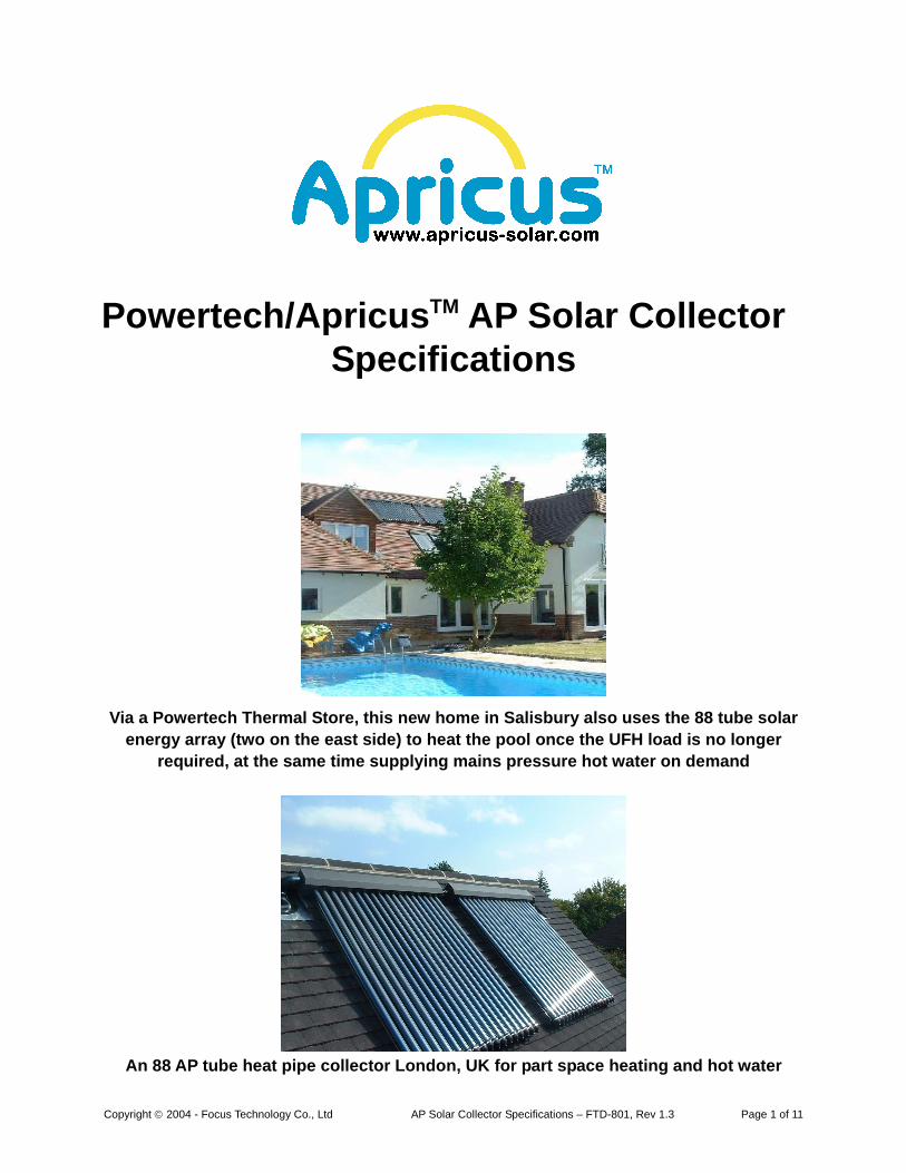
Via a Powertech Thermal Store, this new home in Sal isbury also uses the 88 tube solar
energy array (two on the east side) to heat the poo l once the UFH load is no longer required, at the same time supplying mains pressure hot water on demand
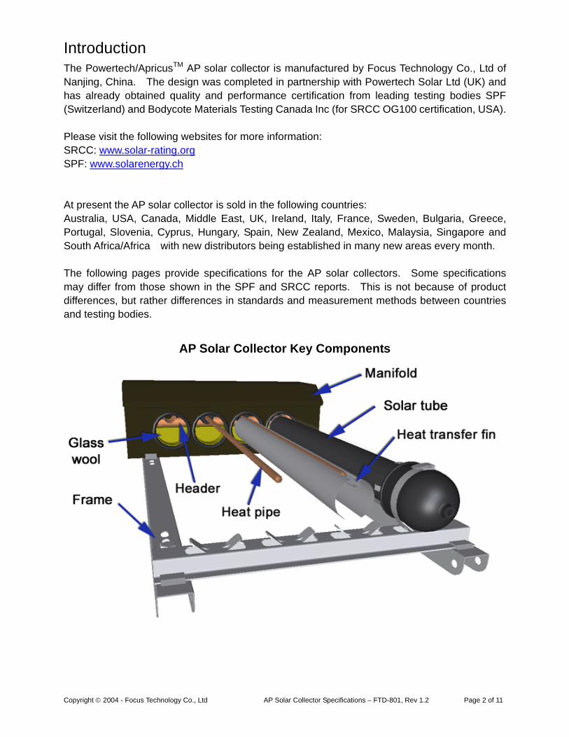
An 88 AP tube heat pipe collector London, UK for pa rt space heating and hot water
Copyright 2004 - Focus Technology Co., Ltd AP Solar Collector Specifications – FTD-801, Rev 1.2 Page 2 of 11
Introduction The Powertech/ApricusTM AP solar collector is manufactured by Focus Technology Co., Ltd of Nanjing, China. The design was completed in partnership with Powertech Solar Ltd (UK) and has already obtained quality and performance certification from leading testing bodies SPF (Switzerland) and Bodycote Materials Testing Canada Inc (for SRCC OG100 certification, USA). Please visit the following websites for more information: SRCC: www.solar-rating.org SPF: www.solarenergy.ch
At present the AP solar collector is sold in the following countries: Australia, USA, Canada, Middle East, UK, Ireland, Italy, France, Sweden, Bulgaria, Greece, Portugal, Slovenia, Cyprus, Hungary, Spain, New Zealand, Mexico, Malaysia, Singapore and South Africa/Africa with new distributors being established in many new areas every month. The following pages provide specifications for the AP solar collectors. Some specifications may differ from those shown in the SPF and SRCC reports. This is not because of product differences, but rather differences in standards and measurement methods between countries and testing bodies.
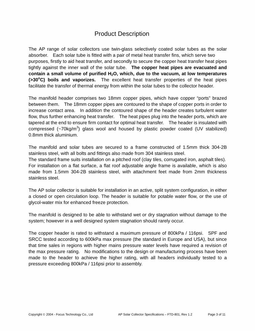
AP Solar Collector Key Components
Copyright 2004 - Focus Technology Co., Ltd AP Solar Collector Specifications – FTD-801, Rev 1.2 Page 3 of 11
Product Description
The AP range of solar collectors use twin-glass selectively coated solar tubes as the solar absorber. Each solar tube is fitted with a pair of metal heat transfer fins, which serve two purposes, firstly to aid heat transfer, and secondly to secure the copper heat transfer heat pipes tightly against the inner wall of the solar tube. The copper heat pipes are evacuated and contain a small volume of purified H 2O, which, due to the vacuum, at low temperatures (>30oC) boils and vaporizes. The excellent heat transfer properties of the heat pipes facilitate the transfer of thermal energy from within the solar tubes to the collector header. The manifold header comprises two 18mm copper pipes, which have copper “ports” brazed between them. The 18mm copper pipes are contoured to the shape of copper ports in order to increase contact area. In addition the contoured shape of the header creates turbulent water flow, thus further enhancing heat transfer. The heat pipes plug into the header ports, which are tapered at the end to ensure firm contact for optimal heat transfer. The header is insulated with compressed (~70kg/m3) glass wool and housed by plastic powder coated (UV stabilized) 0.8mm thick aluminium. The manifold and solar tubes are secured to a frame constructed of 1.5mm thick 304-2B stainless steel, with all bolts and fittings also made from 304 stainless steel. The standard frame suits installation on a pitched roof (clay tiles, corrugated iron, asphalt tiles). For installation on a flat surface, a flat roof adjustable angle frame is available, which is also made from 1.5mm 304-2B stainless steel, with attachment feet made from 2mm thickness stainless steel. The AP solar collector is suitable for installation in an active, split system configuration, in either a closed or open circulation loop. The header is suitable for potable water flow, or the use of glycol-water mix for enhanced freeze protection. The manifold is designed to be able to withstand wet or dry stagnation without damage to the system; however in a well designed system stagnation should rarely occur. The copper header is rated to withstand a maximum pressure of 800kPa / 116psi. SPF and SRCC tested according to 600kPa max pressure (the standard in Europe and USA), but since that time sales in regions with higher mains pressure water levels have required a revision of the max pressure rating. No modifications to the design or manufacturing process have been made to the header to achieve the higher rating, with all headers individually tested to a pressure exceeding 800kPa / 116psi prior to assembly.
Copyright 2004 - Focus Technology Co., Ltd AP Solar Collector Specifications – FTD-801, Rev 1.2 Page 4 of 11
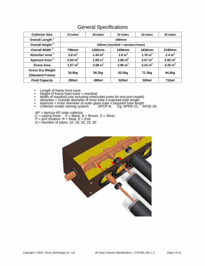
General Specifications Collector Size 10 tubes 18 tubes 20 tubes 22 tubes 30 tubes
Overall Length 1 1980mm
Overall Height 2 156mm (manifold + standard frame)
Overall Width 3 796mm 1356mm 1496mm 1636mm 2196mm
Absorber Area 4 0.8 m2 1.44 m2 1.6 m2 1.76 m2 2.4 m2
Aperture Area 5 0.94 m2 1.69 m2 1.88 m2 2.07 m2 2.82 m2
Gross Area 1.57 m 2 2.68 m2 2.96 m2 3.23 m2 4.35 m2
Gross Dry Weight
(Standard Frame) 34.8kg 58.2kg 63.5kg 71.3kg 94.8kg
Fluid Capacity 290ml 490ml 520ml 550ml 710ml
• Length of frame front track • Height of frame front track + manifold • Width of manifold (not including inlet/outlet ports for end port model) • Absorber = Outside diameter of inner tube x exposed tube length • Aperture = Inner diameter of outer glass tube x exposed tube length • Collector model naming system: APCP-N. Eg. APKR-22, APSE-30
AP = Apricus AP solar collector C = casing finish: K = Black, B = Brown, S = Silver P = port location: R = Rear, E = End N = Number of tubes: 10, 18, 20, 22, 30
Copyright 2004 - Focus Technology Co., Ltd AP Solar Collector Specifications – FTD-801, Rev 1.2 Page 5 of 11
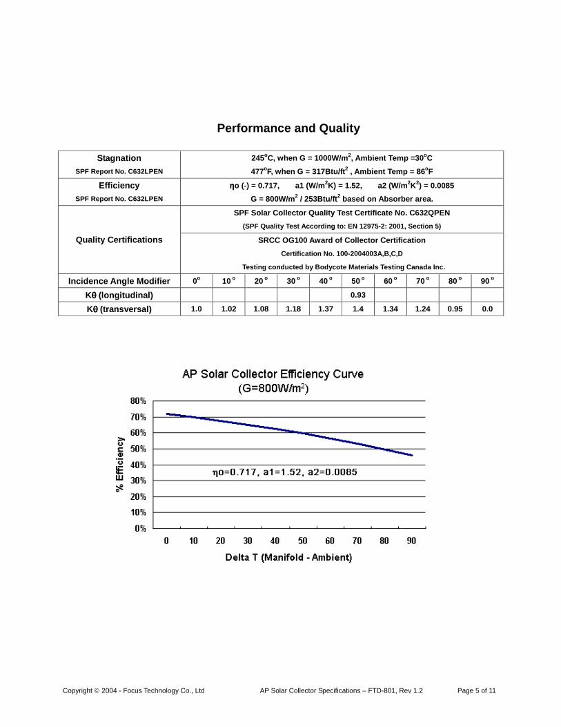
Performance and Quality
Stagnation SPF Report No. C632LPEN
245oC, when G = 1000W/m 2, Ambient Temp =30 oC
477oF, when G = 317Btu/ft 2 , Ambient Temp = 86 oF
Efficiency SPF Report No. C632LPEN
ηηηηo (-) = 0.717, a1 (W/m 2K) = 1.52, a2 (W/m 2K2) = 0.0085
G = 800W/m2 / 253Btu/ft 2 based on Absorber area.
SPF Solar Collector Quality Test Certificate No. C6 32QPEN
(SPF Quality Test According to: EN 12975-2: 2001, S ection 5)
Quality Certifications SRCC OG100 Award of Collector Certification
Certification No. 100-2004003A,B,C,D
Testing conducted by Bodycote Materials Testing Ca nada Inc.
Incidence Angle Modifier 0o 10 o 20 o 30 o 40 o 50 o 60 o 70 o 80 o 90 o
Kθθθθ (longitudinal) 0.93
Kθθθθ (transversal) 1.0 1.02 1.08 1.18 1.37 1.4 1.34 1.24 0.95 0.0
Copyright 2004 - Focus Technology Co., Ltd AP Solar Collector Specifications – FTD-801, Rev 1.2 Page 6 of 11
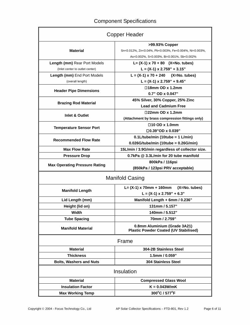
Component Specifications
Copper Header
Material
>99.93% Copper Sn<0.012%, Zn<0.04%, Pb<0.003%, Fe<0.004%, Ni<0.003%,
As<0.002%, S<0.003%, Bi<0.001%, Sb<0.002%
Length (mm) Rear Port Models
(Inlet center to outlet center)
L= (X-1) x 70 + 80 (X=No. tubes)
L = (X-1) x 2.759” + 3.15”
Length (mm) End Port Models
(overall length)
L = (X-1) x 70 + 240 (X=No. tubes)
L = (X-1) x 2.759” + 9.45”
Header Pipe Dimensions ∅∅∅∅18mm OD x 1.2mm
0.7” OD x 0.047”
Brazing Rod Material 45% Silver, 30% Copper, 25% Zinc
Lead and Cadmium Free
Inlet & Outlet ∅∅∅∅22mm OD x 1.2mm
(Attachment by brass compression fittings only)
Temperature Sensor Port ∅∅∅∅10 OD x 1.0mm
∅∅∅∅0.39”OD x 0.039”
Recommended Flow Rate 0.1L/tube/min (10tube = 1 L/min)
0.026G/tube/min (10tube = 0.26G/min)
Max Flow Rate 15L/min / 3.9G/min regardless of collect or size.
Pressure Drop 0.7kPa @ 3.3L/min for 20 tube manifold
Max Operating Pressure Rating 800kPa / 116psi
(850kPa / 123psi PRV acceptable)
Manifold Casing
Manifold Length L= (X-1) x 70mm + 160mm (X=No. tubes)
L = (X-1) x 2.759” + 6.3”
Lid Length (mm) Manifold Length + 6mm / 0.236”
Height (lid on) 131mm / 5.157”
Width 140mm / 5.512”
Tube Spacing 70mm / 2.759”
Manifold Material 0.8mm Aluminium (Grade 3A21) Plastic Powder Coated (UV Stabilised)
Frame Material 304-2B Stainless Steel
Thickness 1.5mm / 0.059”
Bolts, Washers and Nuts 304 Stainless Steel
Insulation
Material Compressed Glass Wool
Insulation Factor K = 0.043W/mK
Max Working Temp 300 oC / 577oF
Copyright 2004 - Focus Technology Co., Ltd AP Solar Collector Specifications – FTD-801, Rev 1.2 Page 7 of 11
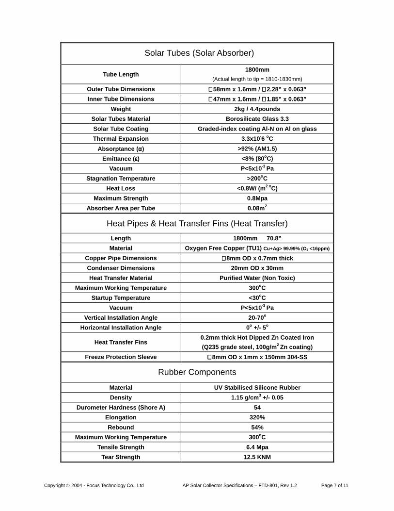
Solar Tubes (Solar Absorber)
Tube Length 1800mm
(Actual length to tip = 1810-1830mm)
Outer Tube Dimensions ∅∅∅∅58mm x 1.6mm / ∅∅∅∅2.28” x 0.063”
Inner Tube Dimensions ∅∅∅∅47mm x 1.6mm / ∅∅∅∅1.85” x 0.063”
Weight 2kg / 4.4pounds
Solar Tubes Material Borosilicate Glass 3.3
Solar Tube Coating Graded-index coating Al-N on Al on glass
Thermal Expansion 3.3x10 -6 oC
Absorptance ( αααα) >92% (AM1.5)
Emittance ( εεεε) <8% (80oC)
Vacuum P<5x10⁻³ Pa
Stagnation Temperature >200 oC
Heat Loss <0.8W/ (m2 oC)
Maximum Strength 0.8Mpa
Absorber Area per Tube 0.08m 2
Heat Pipes & Heat Transfer Fins (Heat Transfer)
Length 1800mm 70.8”
Material Oxygen Free Copper (TU1) Cu+Ag> 99.99% (O 2 <16ppm)
Copper Pipe Dimensions ∅∅∅∅8mm OD x 0.7mm thick
Condenser Dimensions 20mm OD x 30mm
Heat Transfer Material Purified Water (Non Toxic)
Maximum Working Temperature 300 oC
Startup Temperature <30 oC
Vacuum P<5x10⁻³ Pa
Vertical Installation Angle 20-70 o
Horizontal Installation Angle 0 o +/- 5o
Heat Transfer Fins 0.2mm thick Hot Dipped Zn Coated Iron
(Q235 grade steel, 100g/m 2 Zn coating)
Freeze Protection Sleeve ∅∅∅∅8mm OD x 1mm x 150mm 304-SS
Rubber Components
Material UV Stabilised Silicone Rubber
Density 1.15 g/cm 3 +/- 0.05
Durometer Hardness (Shore A) 54
Elongation 320%
Rebound 54%
Maximum Working Temperature 300 oC
Tensile Strength 6.4 Mpa
Tear Strength 12.5 KNM
Copyright 2004 - Focus Technology Co., Ltd AP Solar Collector Specifications – FTD-801, Rev 1.2 Page 8 of 11
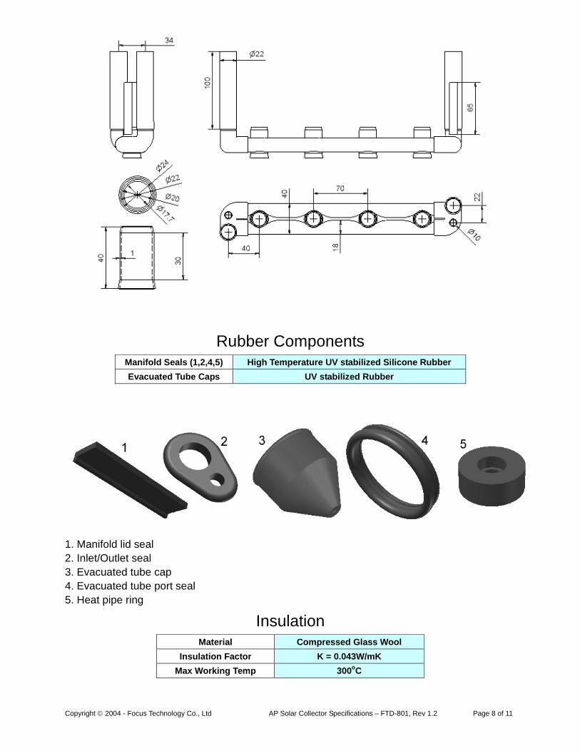
Rubber Components Manifold Seals (1,2,4,5) High Temperature UV stabilized Silicone Rubber
Evacuated Tube Caps UV stabilized Rubber
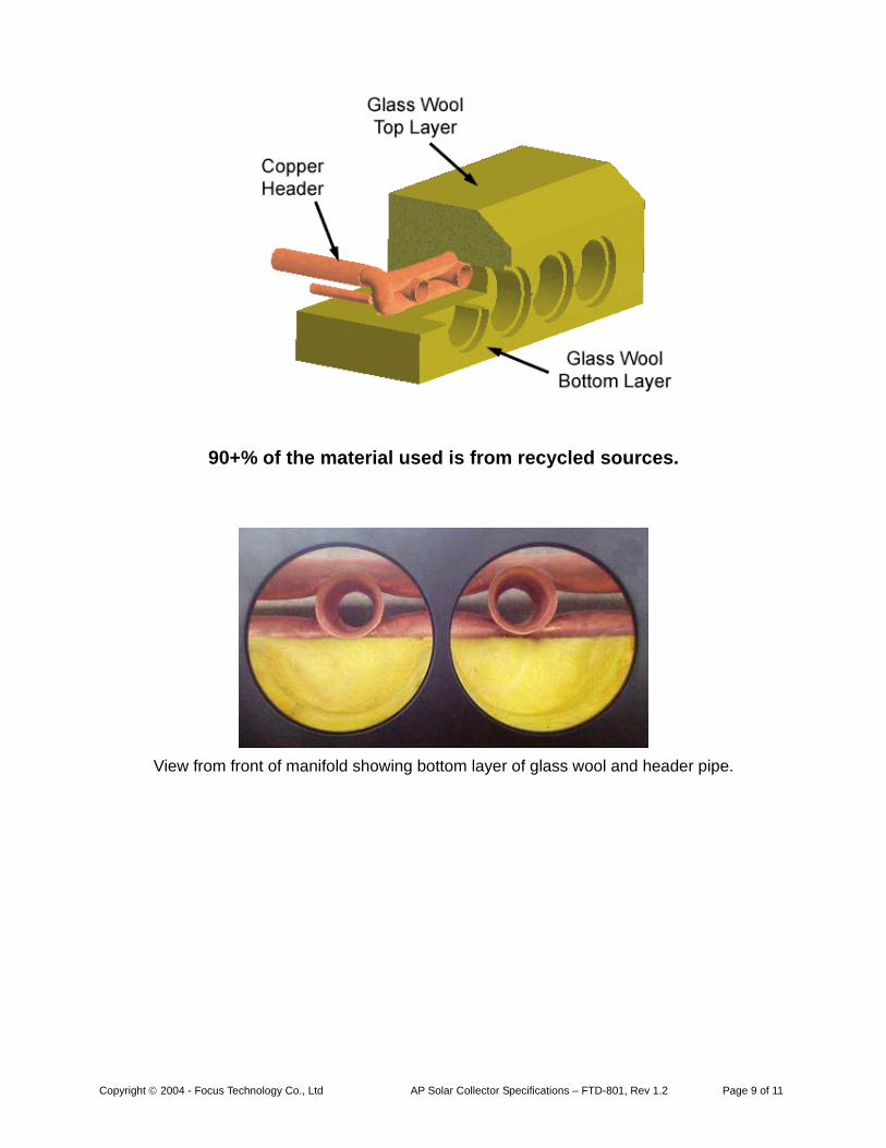
1. Manifold lid seal 2. Inlet/Outlet seal 3. Evacuated tube cap 4. Evacuated tube port seal 5. Heat pipe ring
Insulation Material Compressed Glass Wool
Insulation Factor K = 0.043W/mK
Max Working Temp 300oC
Copyright 2004 - Focus Technology Co., Ltd AP Solar Collector Specifications – FTD-801, Rev 1.2 Page 9 of 11
90+% of the material used is from recycled sources.
View from front of manifold showing bottom layer of glass wool and header pipe.
Copyright 2004 - Focus Technology Co., Ltd AP Solar Collector Specifications – FTD-801, Rev 1.2 Page 10 of 11
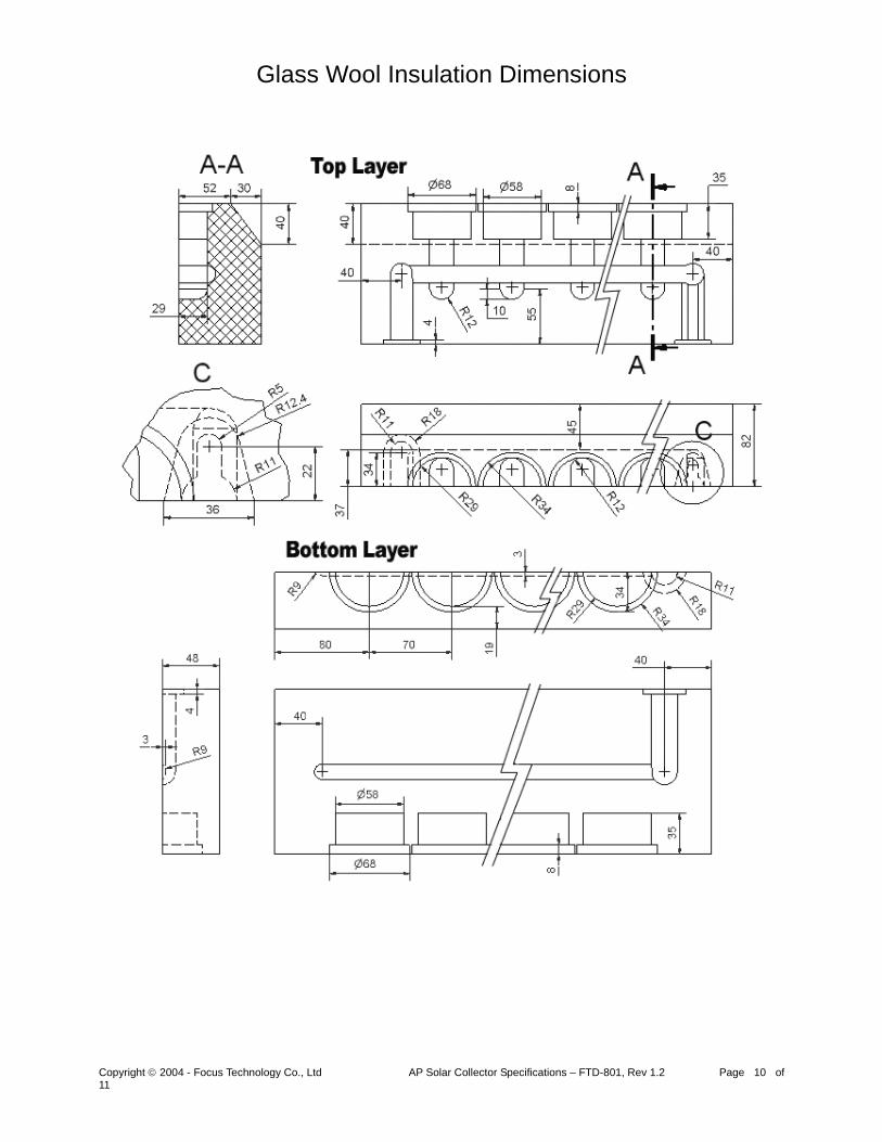
Glass Wool Insulation Dimensions
Copyright 2004 - Focus Technology Co., Ltd AP Solar Collector Specifications – FTD-801, Rev 1.2 Page 11 of 11
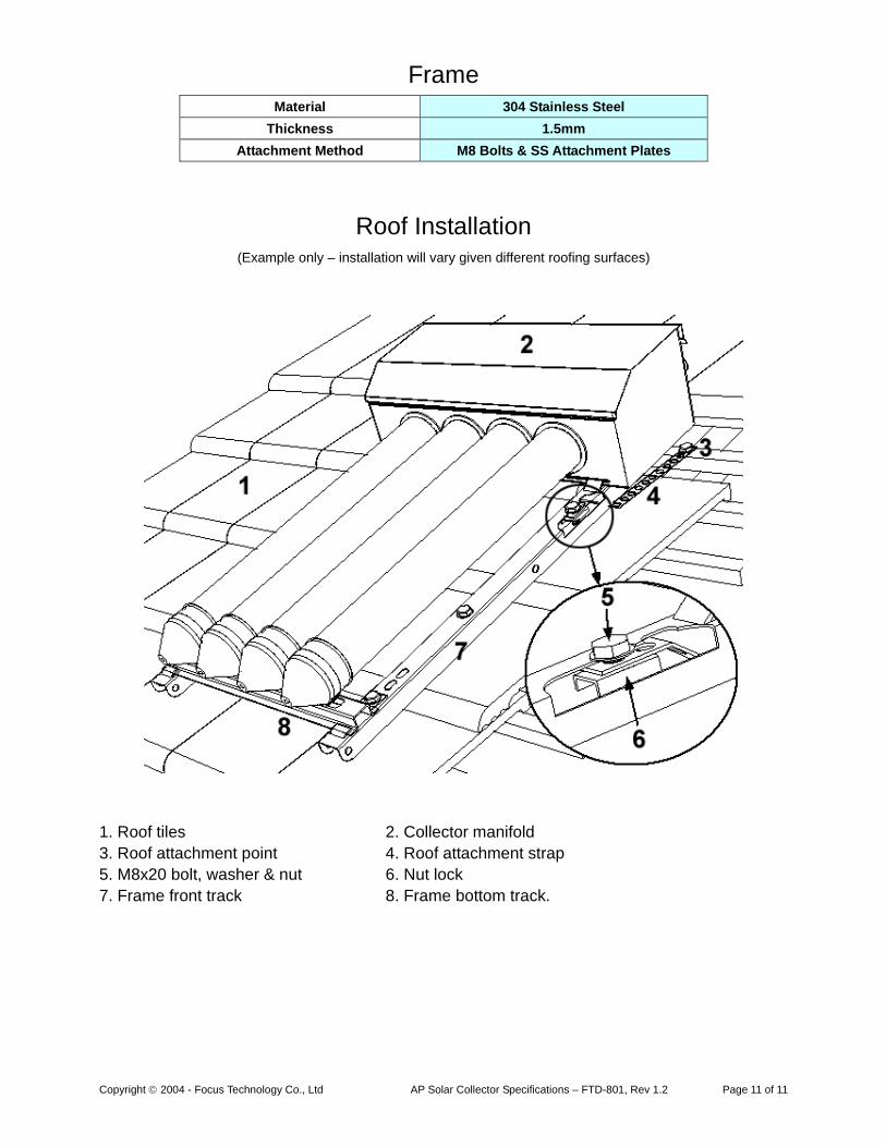
Frame Material 304 Stainless Steel
Thickness 1.5mm
Attachment Method M8 Bolts & SS Attachment Plates
Roof Installation (Example only – installation will vary given different roofing surfaces)
1. Roof tiles 2. Collector manifold 3. Roof attachment point 4. Roof attachment strap 5. M8x20 bolt, washer & nut 6. Nut lock 7. Frame front track 8. Frame bottom track.

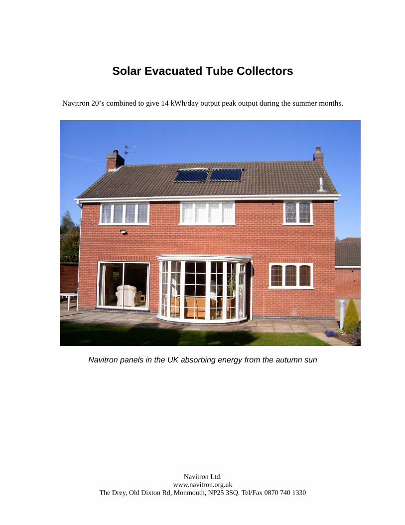
Solar Evacuated Tube Collectors
Navitron 20’s combined to give 14 kWh/day output peak output during the summer months.
Navitron panels in the UK absorbing energy from the autumn sun
Navitron Ltd. www.navitron.org.uk
The Drey, Old Dixton Rd, Monmouth, NP25 3SQ. Tel/Fax 0870 740 1330
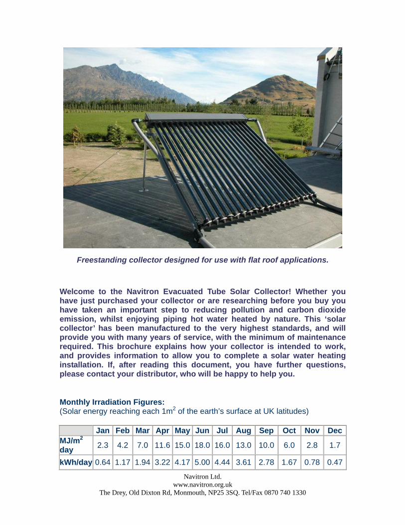
Freestanding collector designed for use with flat roof applications.
Welcome to the Navitron Evacuated Tube Solar Collector! Whether you have just purchased your collector or are researching before you buy you have taken an important step to reducing pollution and carbon dioxide emission, whilst enjoying piping hot water heated by nature. This ‘solar collector’ has been manufactured to the very highest standards, and will provide you with many years of service, with the minimum of maintenance required. This brochure explains how your collector is intended to work, and provides information to allow you to complete a solar water heating installation. If, after reading this document, you have further questions, please contact your distributor, who will be happy to help you.
Monthly Irradiation Figures: (Solar energy reaching each 1m2 of the earth’s surface at UK latitudes) Jan Feb Mar Apr May Jun Jul Aug Sep Oct Nov DecMJ/m2 day 2.3 4.2 7.0 11.6 15.0 18.0 16.0 13.0 10.0 6.0 2.8 1.7
kWh/day 0.64 1.17 1.94 3.22 4.17 5.00 4.44 3.61 2.78 1.67 0.78 0.47
Navitron Ltd. www.navitron.org.uk
The Drey, Old Dixton Rd, Monmouth, NP25 3SQ. Tel/Fax 0870 740 1330
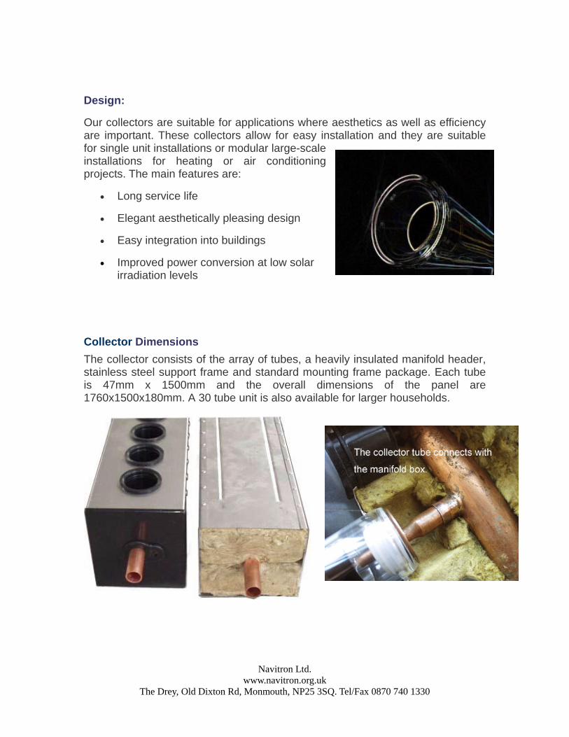
Design:
Our collectors are suitable for applications where aesthetics as well as efficiency are important. These collectors allow for easy installation and they are suitable for single unit installations or modular large-scale installations for heating or air conditioning projects. The main features are:
• Long service life
• Elegant aesthetically pleasing design
• Easy integration into buildings
• Improved power conversion at low solar irradiation levels
Collector Dimensions The collector consists of the array of tubes, a heavily insulated manifold header, stainless steel support frame and standard mounting frame package. Each tube is 47mm x 1500mm and the overall dimensions of the panel are 1760x1500x180mm. A 30 tube unit is also available for larger households.
Navitron Ltd. www.navitron.org.uk
The Drey, Old Dixton Rd, Monmouth, NP25 3SQ. Tel/Fax 0870 740 1330
Vacuum Tubes
Unlike cheaper panels, this system does not heat the water directly within the vacuum tubes. Instead, a sealed copper ‘heat pipe’ transfers the heat via convection of its internal heat transfer fluid to a ‘hot bulb’ that indirectly heats a copper manifold within the header. The heat pipes are inserted into curved absorbers forming an assembly which in inserted into the glass tubes. The tubes are made of borosilicate glass, which is strong and has a high transmittance for solar irradiation. In order to reduce the convection heat lost, the glass tubes are evacuated to vacuum pressure or less than 10-3 Pa. Stable vacuum seals are ensured by using a patented technique employing high heat and pressure. In order to keep the stability of the vacuum for a long time, a barium “getter” is used (the silver coating at the tip of the tube). This rare metal coating absorbs any gases that might eventually enter the tube, increasing the lifespan of the vacuum seal. Through evacuating air out of the glass tube the absorber material and selective coating are protected from corrosion and other environmental influences. This ensures a lifetime of at least 15 years without loss of efficiency. The getter also acts as an indicator and will turn white instantly should the tube be broken.
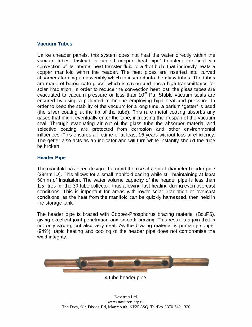
Header Pipe
The manifold has been designed around the use of a small diameter header pipe (28mm ID). This allows for a small manifold casing while still maintaining at least 50mm of insulation. The water volume capacity of the header pipe is less than 1.5 litres for the 30 tube collector, thus allowing fast heating during even overcast conditions. This is important for areas with lower solar irradiation or overcast conditions, as the heat from the manifold can be quickly harnessed, then held in the storage tank.
The header pipe is brazed with Copper-Phosphorus brazing material (BcuP6), giving excellent joint penetration and smooth brazing. This result is a join that is not only strong, but also very neat. As the brazing material is primarily copper (94%), rapid heating and cooling of the header pipe does not compromise the weld integrity.
4 tube header pipe.
Navitron Ltd.
www.navitron.org.uk The Drey, Old Dixton Rd, Monmouth, NP25 3SQ. Tel/Fax 0870 740 1330
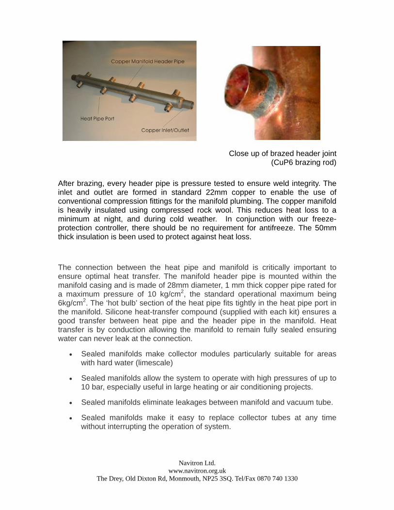
Close up of brazed header joint (CuP6 brazing rod)
After brazing, every header pipe is pressure tested to ensure weld integrity. The inlet and outlet are formed in standard 22mm copper to enable the use of conventional compression fittings for the manifold plumbing. The copper manifold is heavily insulated using compressed rock wool. This reduces heat loss to a minimum at night, and during cold weather. In conjunction with our freeze-protection controller, there should be no requirement for antifreeze. The 50mm thick insulation is been used to protect against heat loss.
The connection between the heat pipe and manifold is critically important to ensure optimal heat transfer. The manifold header pipe is mounted within the manifold casing and is made of 28mm diameter, 1 mm thick copper pipe rated for a maximum pressure of 10 kg/cm2, the standard operational maximum being 6kg/cm2. The ‘hot bulb’ section of the heat pipe fits tightly in the heat pipe port in the manifold. Silicone heat-transfer compound (supplied with each kit) ensures a good transfer between heat pipe and the header pipe in the manifold. Heat transfer is by conduction allowing the manifold to remain fully sealed ensuring water can never leak at the connection.
• Sealed manifolds make collector modules particularly suitable for areas with hard water (limescale)
• Sealed manifolds allow the system to operate with high pressures of up to 10 bar, especially useful in large heating or air conditioning projects.
• Sealed manifolds eliminate leakages between manifold and vacuum tube.
• Sealed manifolds make it easy to replace collector tubes at any time without interrupting the operation of system.
Navitron Ltd. www.navitron.org.uk
The Drey, Old Dixton Rd, Monmouth, NP25 3SQ. Tel/Fax 0870 740 1330
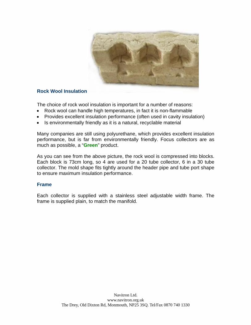
Rock Wool Insulation
The choice of rock wool insulation is important for a number of reasons: • Rock wool can handle high temperatures, in fact it is non-flammable • Provides excellent insulation performance (often used in cavity insulation) • Is environmentally friendly as it is a natural, recyclable material
Many companies are still using polyurethane, which provides excellent insulation performance, but is far from environmentally friendly. Focus collectors are as much as possible, a “Green” product.
As you can see from the above picture, the rock wool is compressed into blocks. Each block is 73cm long, so 4 are used for a 20 tube collector, 6 in a 30 tube collector. The mold shape fits tightly around the header pipe and tube port shape to ensure maximum insulation performance.
Frame
Each collector is supplied with a stainless steel adjustable width frame. The frame is supplied plain, to match the manifold.
Navitron Ltd. www.navitron.org.uk
The Drey, Old Dixton Rd, Monmouth, NP25 3SQ. Tel/Fax 0870 740 1330
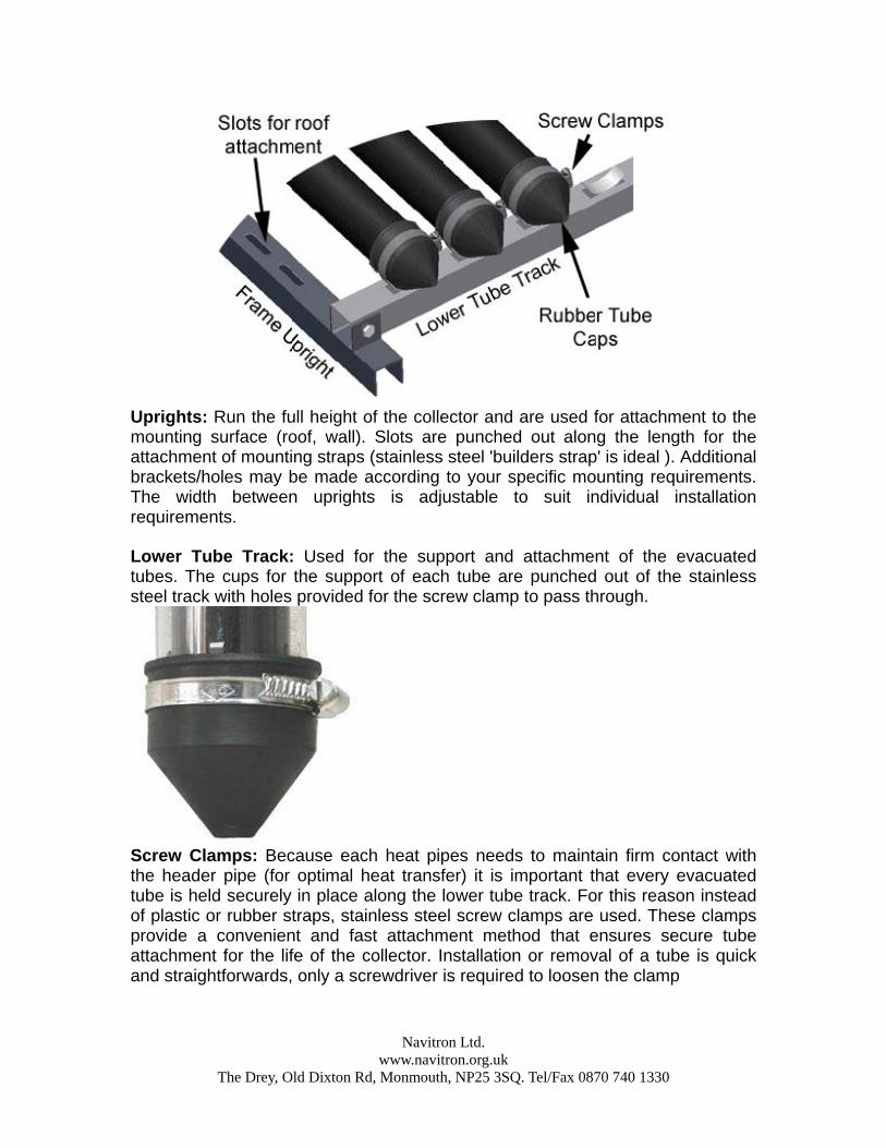
Uprights: Run the full height of the collector and are used for attachment to the mounting surface (roof, wall). Slots are punched out along the length for the attachment of mounting straps (stainless steel 'builders strap' is ideal ). Additional brackets/holes may be made according to your specific mounting requirements. The width between uprights is adjustable to suit individual installation requirements.
Lower Tube Track: Used for the support and attachment of the evacuated tubes. The cups for the support of each tube are punched out of the stainless steel track with holes provided for the screw clamp to pass through.
Screw Clamps: Because each heat pipes needs to maintain firm contact with the header pipe (for optimal heat transfer) it is important that every evacuated tube is held securely in place along the lower tube track. For this reason instead of plastic or rubber straps, stainless steel screw clamps are used. These clamps provide a convenient and fast attachment method that ensures secure tube attachment for the life of the collector. Installation or removal of a tube is quick and straightforwards, only a screwdriver is required to loosen the clamp
Navitron Ltd. www.navitron.org.uk
The Drey, Old Dixton Rd, Monmouth, NP25 3SQ. Tel/Fax 0870 740 1330
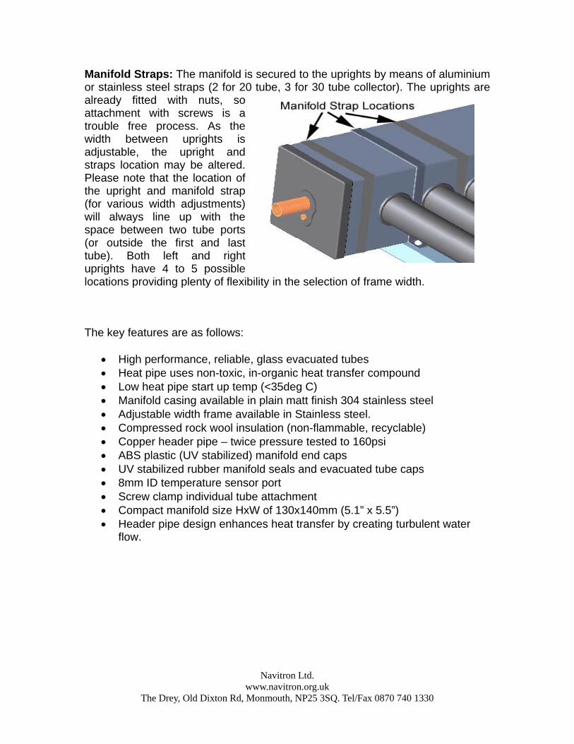
Manifold Straps: The manifold is secured to the uprights by means of aluminium or stainless steel straps (2 for 20 tube, 3 for 30 tube collector). The uprights are already fitted with nuts, so attachment with screws is a trouble free process. As the width between uprights is adjustable, the upright and straps location may be altered. Please note that the location of the upright and manifold strap (for various width adjustments) will always line up with the space between two tube ports (or outside the first
and last
tube). Both left and right uprights have 4 to 5 possible locations providing plenty of flexibility in the selection of frame width.
The key features are as follows:
• High performance, reliable, glass evacuated tubes • Heat pipe uses non-toxic, in-organic heat transfer compound • Low heat pipe start up temp (<35deg C) • Manifold casing available in plain matt finish 304 stainless steel • Adjustable width frame available in Stainless steel. • Compressed rock wool insulation (non-flammable, recyclable) • Copper header pipe – twice pressure tested to 160psi • ABS plastic (UV stabilized) manifold end caps • UV stabilized rubber manifold seals and evacuated tube caps • 8mm ID temperature sensor port • Screw clamp individual tube attachment • Compact manifold size HxW of 130x140mm (5.1” x 5.5”) • Header pipe design enhances heat transfer by creating turbulent water
flow.
Navitron Ltd. www.navitron.org.uk
The Drey, Old Dixton Rd, Monmouth, NP25 3SQ. Tel/Fax 0870 740 1330
Navitron Ltd. www.navitron.org.uk
The Drey, Old Dixton Rd, Monmouth, NP25 3SQ. Tel/Fax 0870 740 1330
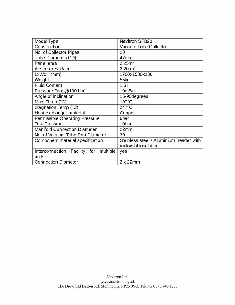
Model Type Navitron SFB20 Construction Vacuum Tube Collector No. of Collector Pipes 20 Tube Diameter (OD) 47mm Panel area 2.25m2 Absorber Surface 2.20 m2 LxWxH (mm) 1760x1500x130 Weight 55kg Fluid Content 1.5 l Pressure Drop@100 l hr-1 10mBar Angle of Inclination 15-90degrees Max. Temp (°C) 190°C Stagnation Temp (°C) 247°C Heat exchanger material Copper Permissible Operating Pressure 6bar Test Pressure 10bar Manifold Connection Diameter 22mm No. of Vacuum Tube Port Diameter 20 Component material specification Stainless steel / Aluminium header with
rockwool insulation Interconnection Facility for multiple units
yes
Connection Diameter 2 x 22mm
Navitron Ltd. www.navitron.org.uk
The Drey, Old Dixton Rd, Monmouth, NP25 3SQ. Tel/Fax 0870 740 1330
Additional Product Information and Background
Sealed Glass Evacuated Tubes
Evacuated tubes are the key component of the solar collector. The following information will provide you with insight into the history, manufacturing process and general specifications of evacuated tubes.
Evacuated Tube History The evacuated tube technology was initially developed by Qing Hua University in Beijing in the early eighties, with pilot manufacturing in 1985. By 1988 annual manufacturing volume by Qing Hua had reached 30,000 tubes. By 1996 with the aid of significant financial support from the Chinese government, Qing Hua reached an annual production capacity of 2 million tubes. Continued infrastructure development led to 2.5 million tubes being sold in 1997.
The majority of the tubes were used to supply the local market, with a small percentage (100,000 in 1995) being supplied to Japan, Europe, South America and South-East Asia. The main barrier to large export sales was the technology of the solar system (tank/manifold). Although the tubes performed well, the quality of the storage tanks was average, and did not meet the requirements of the European market. The non-pressure thermosiphon systems did, however, meet the needs of the Chinese market, and therefore sales grew and grew.
In 1998 Qing Hua held 70% of the Chinese solar water heating market. With the breakup of some of the key members of the Qing Hua Solar board members, the patent protection for the tube technology was no longer enforceable, and so other Chinese companies began producing the evacuated tubes. The equipment and machinery used to produce all tubes in China is therefore the same as that developed by Qing Hua. For this reason, if engineering standards are followed, and good quality raw materials use, all tubes manufactured in China should be the same, and provide the same performance. You will find that all Chinese companies provide tubes with the same specifications. Having said this though, there are many companies who use poor quality raw material and make short cuts on engineering requirements. Selection of a professional tube manufacturer is therefore very important.
Navitron Ltd. www.navitron.org.uk
The Drey, Old Dixton Rd, Monmouth, NP25 3SQ. Tel/Fax 0870 740 1330
Navitron Product Development
Full scale production of the Navitron model solar collector began in early April of 2002. Since then collectors have been sold to the UK, France, Germany, Italy, The Netherlands and Ireland.
Communication with customers and solar experts in Germany, the UK, Italy and the US provided the basis for many of the Navitron design features. For this reason it is very well suited to the needs of these markets, particularly in relation to packing and freight, installation, aesthetics, performance and overall quality.
During the development of this collector it became clear that the European and US market needed a solar collector that met the following criteria:
• High performance evacuated tube heat pipe based design • “Plug and Play” heat pipe system for easy transport, installation and
maintenance (changing broken tubes) • Use of non-toxic heat pipe transfer liquid (not acetone) • High quality long lasting components (corrosion resistant materials) • High quality stainless steel finish • Excellent insulation properties (>50mm thick rock wool) • Small manifold water volume to ensure fast heating time • Environmentally friendly through the use of non-polluting, recyclable
materials • Accept mains pressure water supply (6kg/cm
2 / 85psi)
• Corrosion resistant manifold header pipe (copper) • Suitable for open or closed flow operation • Accept a standard sized temperature sensor • Compact frame that could be packed with the manifold • Adjustable width frame to allow for varying installation surfaces • Quick and simple tube attachment system – permitting easy removal of
any one tube • Compact manifold size • Cost competitive with high quality flat plate collectors
Certification Please note that the Navitron collector is manufactured in accordance with ISO9002, and it is currently undergoing testing to BS EN 12975 It is from these tests that the absorption (93%) and emission (7%) efficiency values have been verified. The glass manufacturing plant, ensures that quality is controlled throughout every step of the process. They have obtained a wide range of quality management and quality control certificates including the internationally recognized ISO9002 management standard.
EVACUATED TUBE & HEAT PIPE CHARACTERISTICS The heat pipe and evacuated tube will not get hot after one minute of sitting in the sun – so don’t expect it too. The sealed glass tubes have a short start-up time as the inner glass tube, heat pipe fins and air within the tube must first be heated before the temperature will start to rise considerably. In good conditions it will take less than 5 minutes for the tip of the heat pipe to get too hot to hold (>50deg C). The advantage of the sealed glass evacuated tube is that is acts as a heat store, providing a stable supply of heat to the manifold even during intermittently overcast weather. The tube will continue to provide heat even after the sun has set. A good test to show the heat storage capacity of the tube is to let the tube heat up outside until the heat pipe tip is hot. Run the tip under cold water for 10 seconds or so to cool it down (drain some of the heat). Stand the tube back up, and within seconds the tip will be red hot again. This can be repeated several times before the heat is “used up”. Another example of the heat storage is to let a tube heat up outside in the sun, and then bring it inside. You will find after half an hour the tip will still be hot, thus demonstrating the store of heat (energy) inside the tube. The sealed glass evacuated tube provides a stable supply of heat even during intermittent weather. There is minimal “peaking and troughing” of heat supply as the clouds intermittently block the sunlight. Heat supply can therefore continue even when there is no sunlight striking the collector, due to the store of heat within the evacuated tube.
Navitron Ltd. www.navitron.org.uk
The Drey, Old Dixton Rd, Monmouth, NP25 3SQ. Tel/Fax 0870 740 1330
NB – DO NOT EXPOSE TUBES TO SUNLIGHT FOR EXTENDED PERIODS WITHOUT COOLING THE TIPS, OR DAMAGE MAY OCCUR. Install header first, and shade tubes from sunlight until the water flow and control is operational
Heat Pipes In addition to the evacuated tubes the copper heat pipe is also vital to the performance of the collector. The heat pipe is an essential link in the heat transfer chain. If this link is poor quality then the efficiency of the whole system will be compromised, regardless of how good the evacuated tubes are.
The key factors to consider when choosing a heat pipe are: • Operating Temperature Range • Heat transfer compound • Heat transfer performance • Operating life expectancy
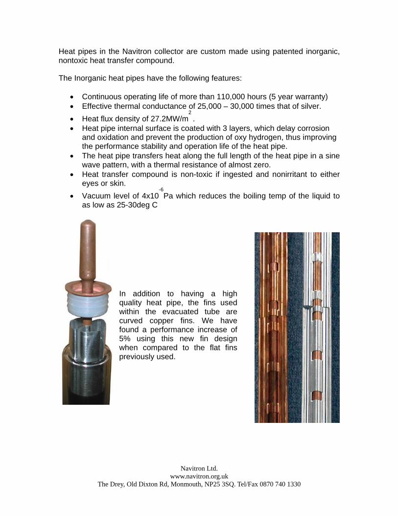
Heat pipes in the Navitron collector are custom made using patented inorganic, nontoxic heat transfer compound.
The Inorganic heat pipes have the following features:
• Continuous operating life of more than 110,000 hours (5 year warranty) • Effective thermal conductance of 25,000 – 30,000 times that of silver. • Heat flux density of 27.2MW/m
2 .
• Heat pipe internal surface is coated with 3 layers, which delay corrosion and oxidation and prevent the production of oxy hydrogen, thus improving the performance stability and operation life of the heat pipe.
• The heat pipe transfers heat along the full length of the heat pipe in a sine wave pattern, with a thermal resistance of almost zero.
• Heat transfer compound is non-toxic if ingested and nonirritant to either eyes or skin.
• Vacuum level of 4x10⁻⁶
Pa which reduces the boiling temp of the liquid to as low as 25-30deg C
In addition to having a high quality heat pipe, the fins used within the evacuated tube are curved copper fins. We have found a performance increase of 5% using this new fin design when compared to the flat fins previously used.
Navitron Ltd. www.navitron.org.uk
The Drey, Old Dixton Rd, Monmouth, NP25 3SQ. Tel/Fax 0870 740 1330
HEAT PIPE CHARACTERISTICS
The heat pipes used by Navitron Ltd are different to some other heat pipes, which use acetone as the heat transfer compound. Acetone heat pipes will transfer heat with just the bottom 5 to 10cm placed in a cup of hot water (50deg C). Ours will not. This is not because the performance is poor, but rather because the nature of the heat transfer compound is quite different. Under the vacuum conditions that exist in the heat pipe, and at low heat pipe temperatures (<30
oC), this mixture will form a frozen “ball” located in the heat pipe tip. For this
reason, when you vigorously shake the heat pipe you will hear a rattling sound and feel an object in the heat pipe tip. If you were to cut the heat pipe open, the vacuum will be lost and you will not find any ball inside, just some orange colored liquid.
The presence of this “ball” indicates the heat pipe has a good vacuum level – although you must consider the ambient air temperature when doing this test. If the ambient temperature is already 30deg the ball may have mostly melted and so no sound will be heard.
If you heat the bottom of the heat pipe with a moderate temperature liquid (50o
C), the heat will not be enough to travel to the tip and “melt” the ball. If however you pour that same temperature water along the length of the heat pipe, the heat will quickly melt the ball and heat transfer to the tip will rapidly occur.
As the evacuated tube provides heat along the full length of the heat pipe, rapid “melting” of the ball and subsequent heat transfer will occur at temperatures as low as 30deg C. As you expose the heat pipe to hotter and hotter temperatures, the ball will continue to melt and contribute to the heat transfer process. Once a hot enough temperature is reached the ball will have totally melted and there will be no sound if shaken.
For demonstration purposes, hot water (>45 deg C) can be poured along the bottom two-thirds of the heat pipe. This will ensure rapid melting of the ball and subsequent heat transfer to the tip. Within 60 seconds the tip can achieve a temperature, which is 90-95% of the temperature it is exposed to. The tip can never get hotter than the heat level it is exposed to (not 100% efficient).
Although the heat pipe can transfer heat at temperatures of around 30-35o
C, the heat transfer to the tip will only reach 28-32
o C, which will not feel hot to the
touch. So don’t try and use warm water for demonstration purposes. Use hot water.
Navitron Ltd. www.navitron.org.uk
The Drey, Old Dixton Rd, Monmouth, NP25 3SQ. Tel/Fax 0870 740 1330
NB – DO NOT EXPOSE TUBES TO SUNLIGHT FOR EXTENDED PERIODS WITHOUT COOLING THE TIPS, OR DAMAGE MAY OCCUR. Install header first, and shade tubes from sunlight until the water flow and control is operational
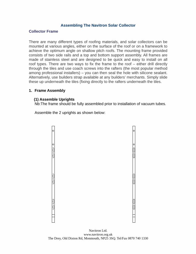
Assembling The Navitron Solar Collector Collector Frame There are many different types of roofing materials, and solar collectors can be mounted at various angles, either on the surface of the roof or on a framework to achieve the optimum angle on shallow pitch roofs. The mounting frame provided consists of two side rails and a top and bottom support assembly. All frames are made of stainless steel and are designed to be quick and easy to install on all roof types. There are two ways to fix the frame to the roof – either drill directly through the tiles and use coach screws into the rafters (the most popular method among professional installers) – you can then seal the hole with silicone sealant. Alternatively, use builders strap available at any builders’ merchants. Simply slide these up underneath the tiles (fixing directly to the rafters underneath the tiles. 1. Frame Assembly
(1) Assemble Uprights Nb:The frame should be fully assembled prior to installation of vacuum tubes. Assemble the 2 uprights as shown below:
Navitron Ltd. www.navitron.org.uk
The Drey, Old Dixton Rd, Monmouth, NP25 3SQ. Tel/Fax 0870 740 1330
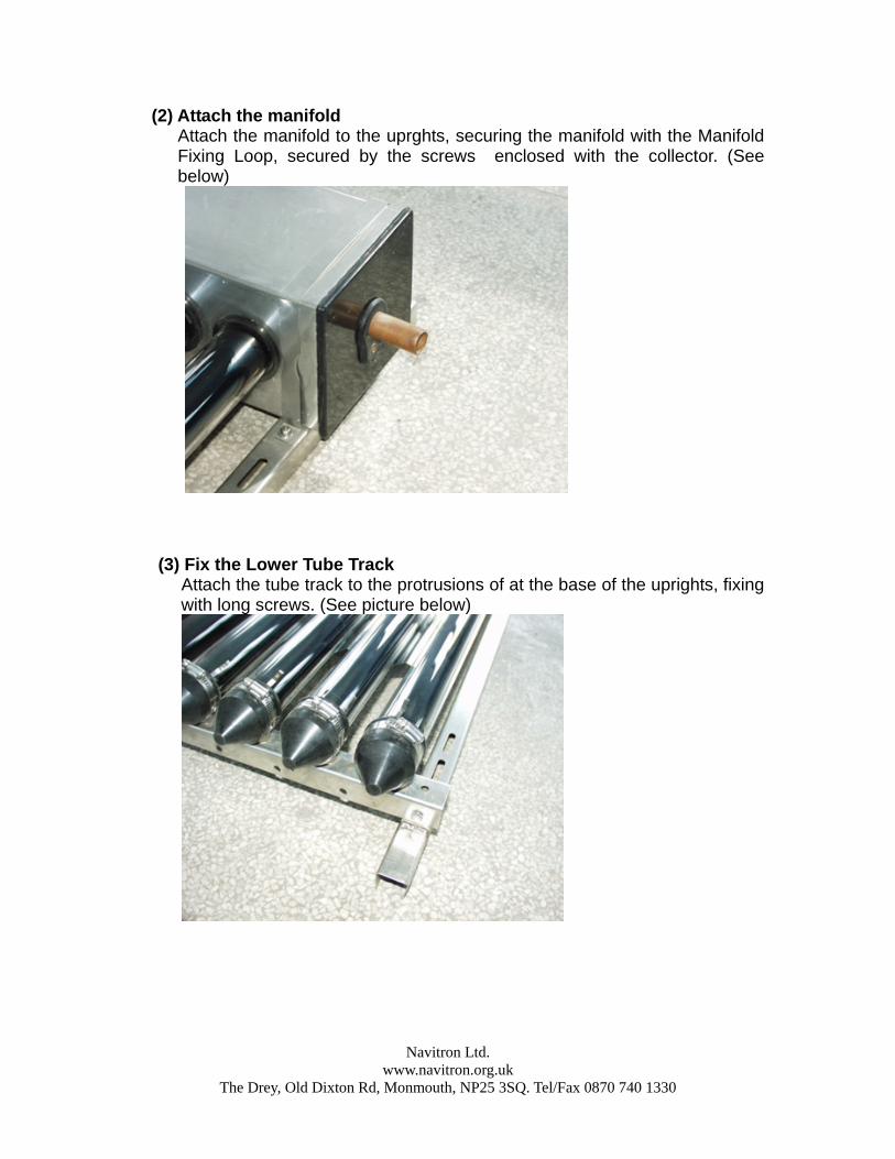
(2) Attach the manifold Attach the manifold to the uprghts, securing the manifold with the Manifold Fixing Loop, secured by the screws enclosed with the collector. (See below)
(3) Fix the Lower Tube Track Attach the tube track to the protrusions of at the base of the uprights, fixing with long screws. (See picture below)
Navitron Ltd. www.navitron.org.uk
The Drey, Old Dixton Rd, Monmouth, NP25 3SQ. Tel/Fax 0870 740 1330
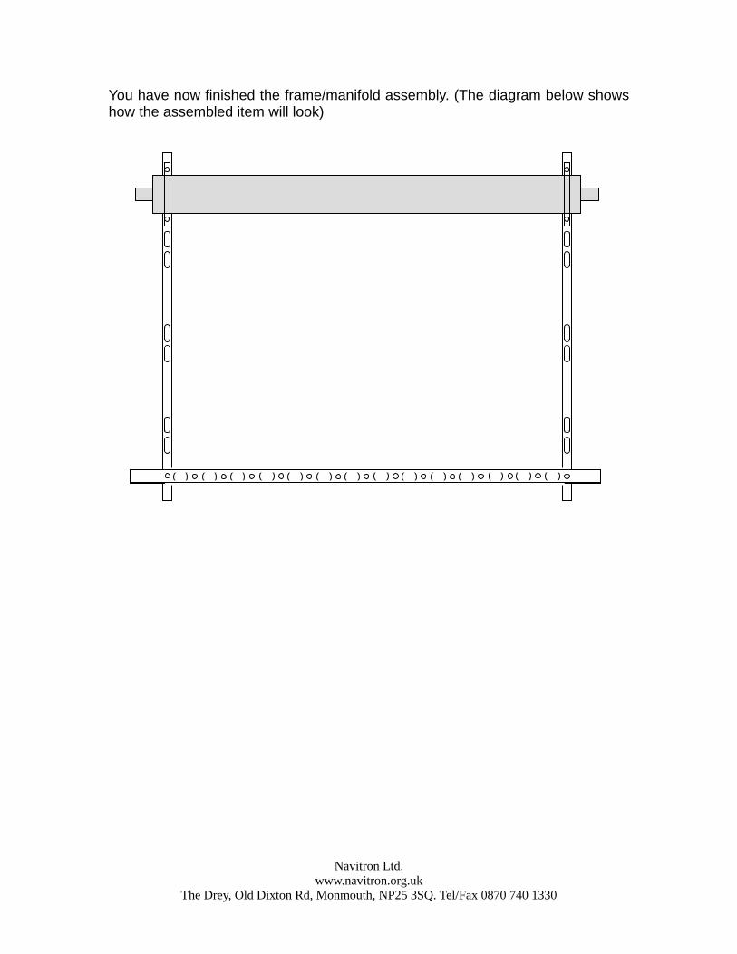
You have now finished the frame/manifold assembly. (The diagram below shows how the assembled item will look)
Navitron Ltd. www.navitron.org.uk
The Drey, Old Dixton Rd, Monmouth, NP25 3SQ. Tel/Fax 0870 740 1330
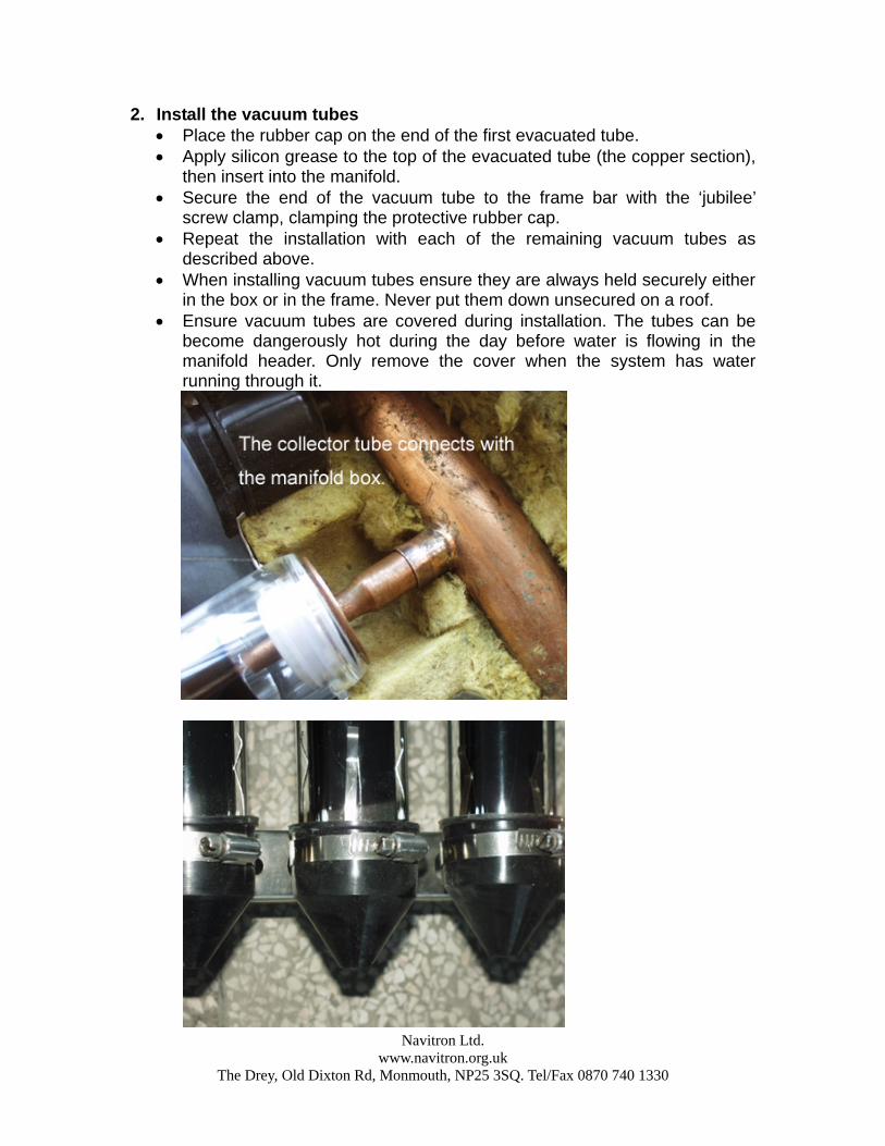
2. Install the vacuum tubes • Place the rubber cap on the end of the first evacuated tube. • Apply silicon grease to the top of the evacuated tube (the copper section),
then insert into the manifold. • Secure the end of the vacuum tube to the frame bar with the ‘jubilee’
screw clamp, clamping the protective rubber cap. • Repeat the installation with each of the remaining vacuum tubes as
described above. • When installing vacuum tubes ensure they are always held securely either
in the box or in the frame. Never put them down unsecured on a roof. • Ensure vacuum tubes are covered during installation. The tubes can be
become dangerously hot during the day before water is flowing in the manifold header. Only remove the cover when the system has water running through it.
Navitron Ltd. www.navitron.org.uk
The Drey, Old Dixton Rd, Monmouth, NP25 3SQ. Tel/Fax 0870 740 1330
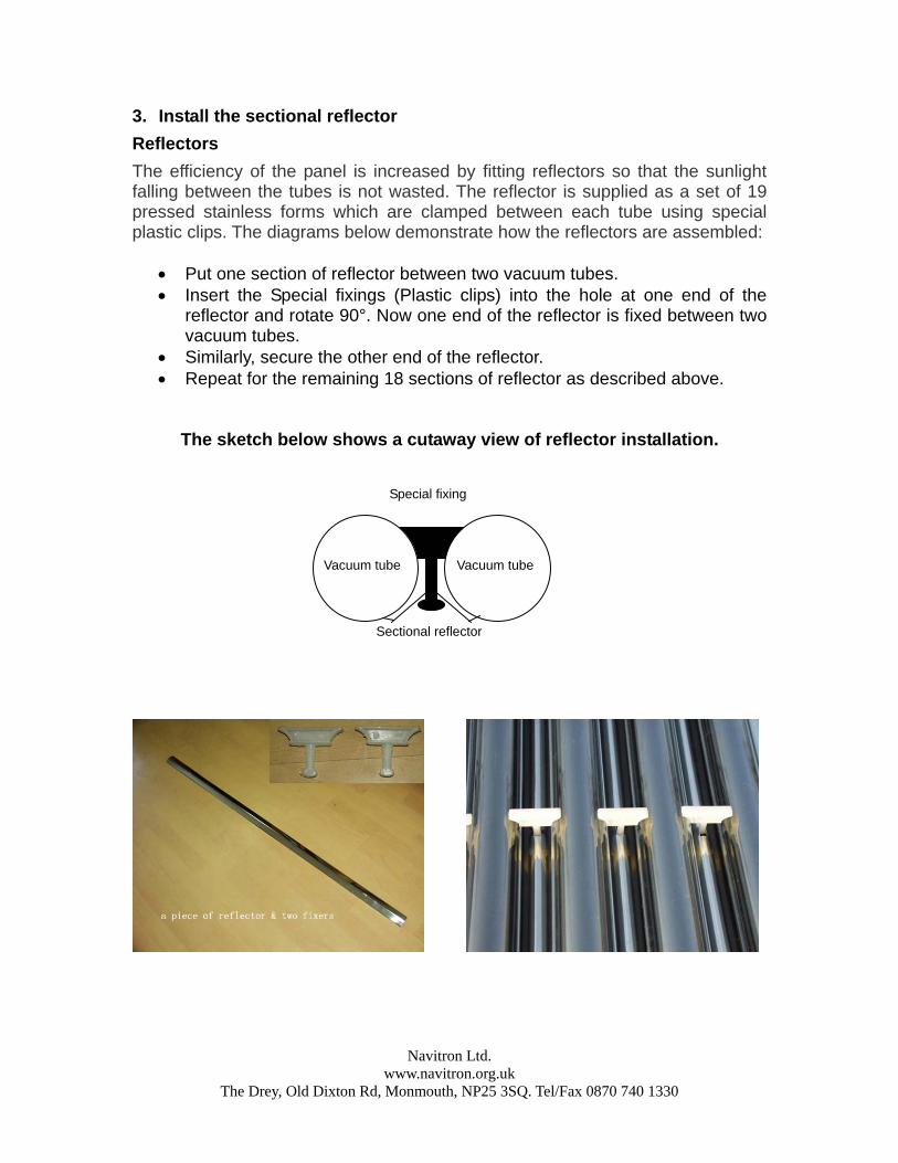
3. Install the sectional reflector Reflectors The efficiency of the panel is increased by fitting reflectors so that the sunlight falling between the tubes is not wasted. The reflector is supplied as a set of 19 pressed stainless forms which are clamped between each tube using special plastic clips. The diagrams below demonstrate how the reflectors are assembled:
• Put one section of reflector between two vacuum tubes. • Insert the Special fixings (Plastic clips) into the hole at one end of the
reflector and rotate 90°. Now one end of the reflector is fixed between two vacuum tubes.
• Similarly, secure the other end of the reflector. • Repeat for the remaining 18 sections of reflector as described above.
The sketch below shows a cutaway view of reflector installation.
Vacuum tube Vacuum tube
Special fixing
Sectional reflector
Navitron Ltd. www.navitron.org.uk
The Drey, Old Dixton Rd, Monmouth, NP25 3SQ. Tel/Fax 0870 740 1330
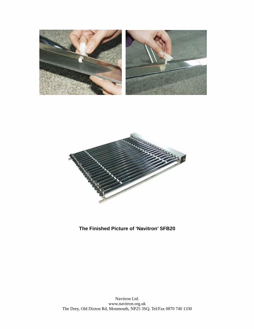
The Finished Picture of ‘Navitron’ SFB20
Navitron Ltd. www.navitron.org.uk
The Drey, Old Dixton Rd, Monmouth, NP25 3SQ. Tel/Fax 0870 740 1330
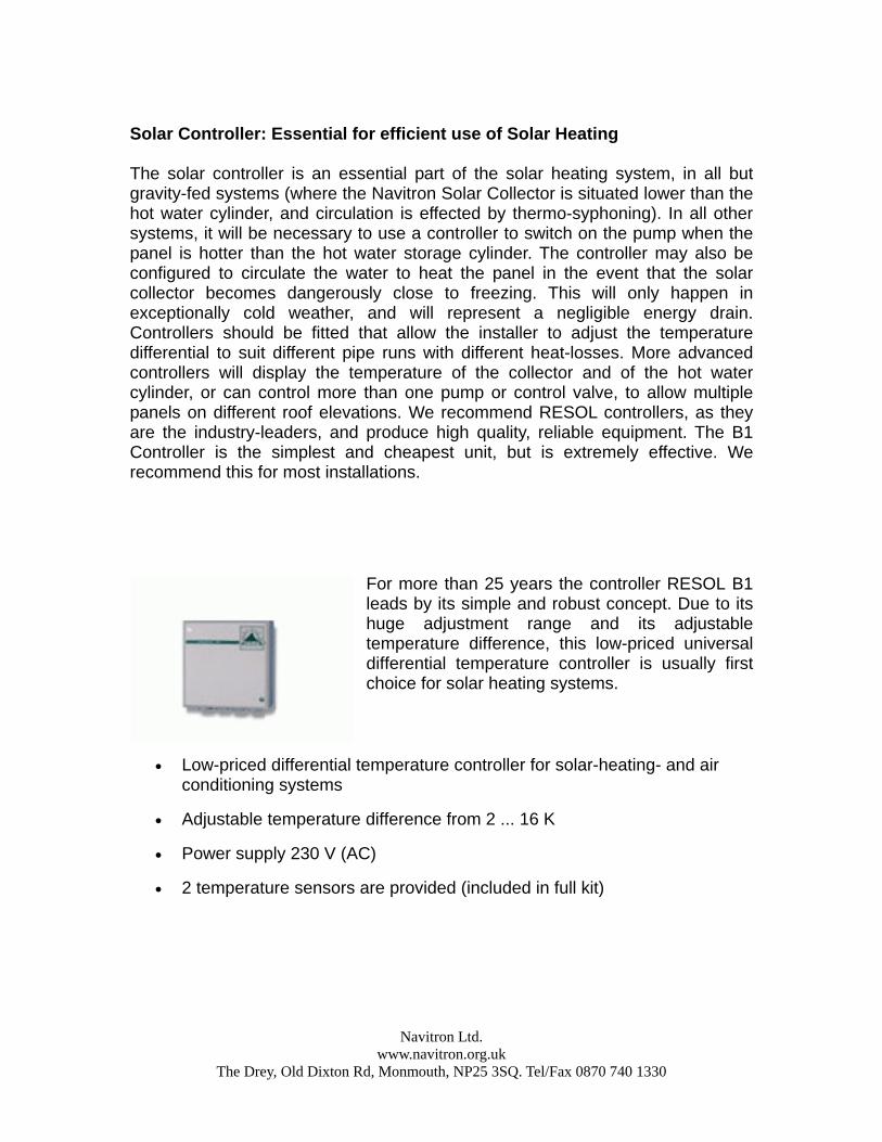
Solar Controller: Essential for efficient use of Solar Heating The solar controller is an essential part of the solar heating system, in all but gravity-fed systems (where the Navitron Solar Collector is situated lower than the hot water cylinder, and circulation is effected by thermo-syphoning). In all other systems, it will be necessary to use a controller to switch on the pump when the panel is hotter than the hot water storage cylinder. The controller may also be configured to circulate the water to heat the panel in the event that the solar collector becomes dangerously close to freezing. This will only happen in exceptionally cold weather, and will represent a negligible energy drain. Controllers should be fitted that allow the installer to adjust the temperature differential to suit different pipe runs with different heat-losses. More advanced controllers will display the temperature of the collector and of the hot water cylinder, or can control more than one pump or control valve, to allow multiple panels on different roof elevations. We recommend RESOL controllers, as they are the industry-leaders, and produce high quality, reliable equipment. The B1 Controller is the simplest and cheapest unit, but is extremely effective. We recommend this for most installations.
For more than 25 years the controller RESOL B1 leads by its simple and robust concept. Due to its huge adjustment range and its adjustable temperature difference, this low-priced universal differential temperature controller is usually first choice for solar heating systems.
• Low-priced differential temperature controller for solar-heating- and air conditioning systems
• Adjustable temperature difference from 2 ... 16 K
• Power supply 230 V (AC)
• 2 temperature sensors are provided (included in full kit)
Navitron Ltd. www.navitron.org.uk
The Drey, Old Dixton Rd, Monmouth, NP25 3SQ. Tel/Fax 0870 740 1330

DeltaSol® B The controller RESOL DeltaSol® B is used for application in standard solar thermal systems as well as in heating and air conditioning systems and persuades by its clear operation concept. A newly developed, multi-functional display enables the user to simultaneously request two temperatures (e.g. collector and store temperature). No annoying switching-over, no guessing but easy pictograms give the user clear information on function and operating status of the controller and the system. The version PG 53.02 is equipped with 2 standard relay outputs, the version PG 51.02 is equipped with 1 standard relay output as well as 3 sensor inputs for Pt1000-sensors, store temperature limitation and manual switch. The central element is the 3-key-field below the display. The newly developed combined LC- display enables an intuitive and reliable controller configuration as well as a comprehensive visualisation of the system status. Collector cooling and recooling function as well as security switch-off, but also a thermostat function can be easily realised. The controller DeltaSol B is also available as individual OEM-version, so that further system adaptions are possible.
Navitron Ltd. www.navitron.org.uk
The Drey, Old Dixton Rd, Monmouth, NP25 3SQ. Tel/Fax 0870 740 1330

Navitron Ltd. www.navitron.org.uk
The Drey, Old Dixton Rd, Monmouth, NP25 3SQ. Tel/Fax 0870 740 1330
Technical data Housing: plastic, PC-ABS and PMMA Protection type: IP 40 / DIN 40050 Size: 172 x 110 x 46 mm Installation: wall mounting, mounting into patch panels is possible Display: LCD, multi-functional combined display with 8 pictograms, two 2-digit text fields and two 4-digit 7-segment displays as well as one 2-coloured luminescent diode Operation: by three pushbuttons in the front of the housing Functions: standard solar controller with adjustable values: minimum- maximum temperature limitation, switch-on and switch-offtemperature difference. Frost protection / cooling function, security
.
Navitron Ltd. www.navitron.org.uk
The Drey, Old Dixton Rd, Monmouth, NP25 3SQ. Tel/Fax 0870 740 1330
Solar Collector Installation
The installation of a Navitron solar collector can be completed in many ways, depending on a number of factors, such as:
• climate (freeze protection, overheating concerns) • storage tank type (mains pressure, thermal store, gravity fed) • flow configuration (open flow, closed flow) • Controller configuration (PV powered pump, Delta T controller) • Installation location (roof, ground, wall) • System size (domestic, large scale application) • System purpose (water heater, central heating, refrigeration)
As a professional solar installer, Navitron expects that you will know how to correctly install the collector to ensure efficient performance and system reliability. We can provide you some technical advice as required, but we may not be that familiar with the specifics of your region. When completing a system design the following points should be noted.
1. The heat pipes do not have a temperature cut off like Thermomax, so pressure release valves and/or expansion chambers are required. Pressure should not exceed 85psi under normal use.
2. The system is well insulated, and subzero temperatures will not damage the evacuated tubes or heat pipes, however the header and associated plumbing may be damaged by if the water freezes. Circulation of water through the collector when ambient temperatures are low is suggested as the best “anti-freeze” method. Electrical supply to the pump must be guaranteed, to account for power blackouts (eg DC pump with battery backup).
3. If using a closed system a glycol water mix can be used to provide adequate freeze protection.
4. The manifold is not guarantee against limescale formation, so ensure that water is of suitable quality (closed loop system is suggested for areas with water that is acidic, hard or has high chloride levels)
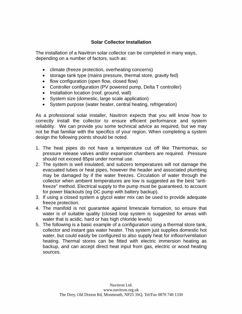
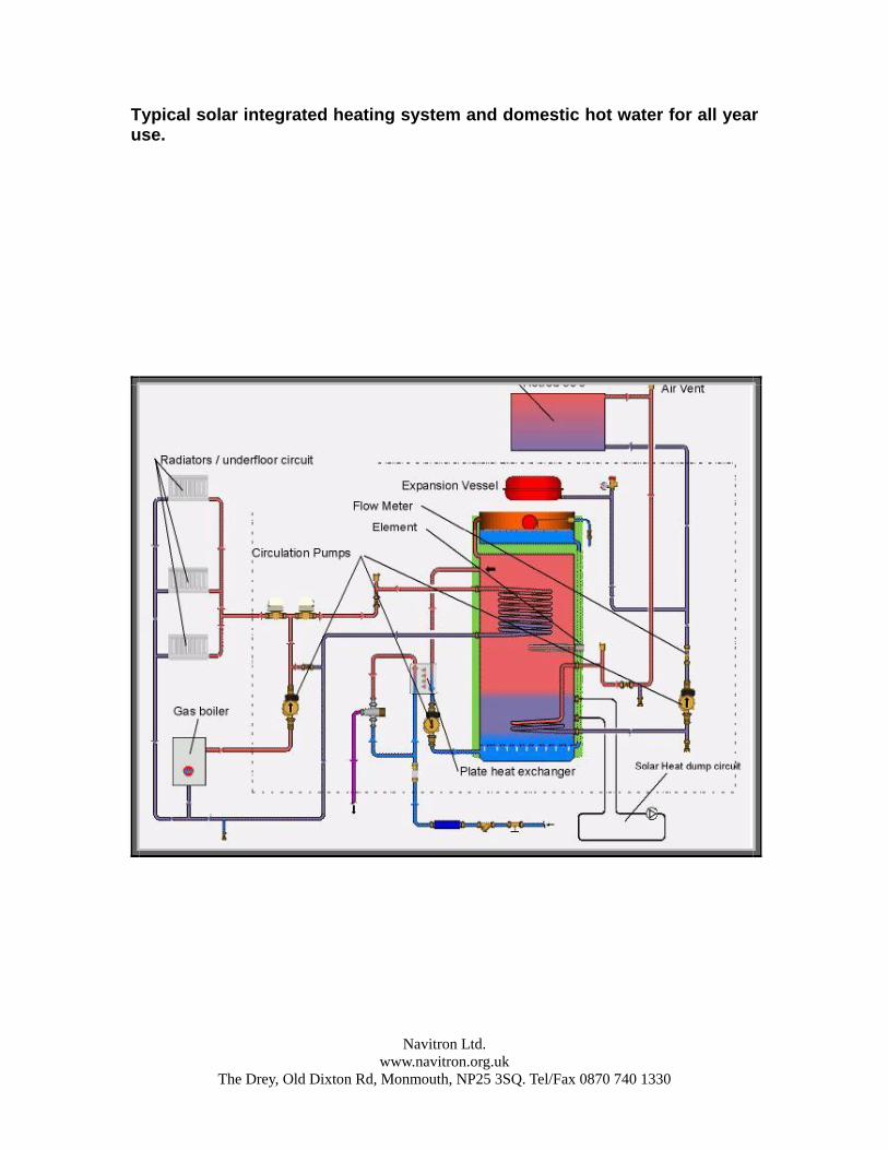
5. The following is a basic example of a configuration using a thermal store tank, collector and instant gas water heater. This system just supplies domestic hot water, but could easily be configured to also supply heat for infloor/ventilation heating. Thermal stores can be fitted with electric immersion heating as backup, and can accept direct heat input from gas, electric or wood heating sources.
Typical solar integrated heating system and domestic hot water for all year use.
Navitron Ltd. www.navitron.org.uk
The Drey, Old Dixton Rd, Monmouth, NP25 3SQ. Tel/Fax 0870 740 1330
Evacuated Tube Solar Domestic Hot water pre heat installation, gas backup
Thermal Stores
Thermal Stores offer the following key features:
• Mains pressure hot water from an open-vented low-pressure tank (via brazed plate heat-exchanger)
• Light, inexpensive and easy to install • Excellent corrosion resistance due to anaerobic tank environment • Provides passive thermal expansion and overheating protection via built in
expansion chamber. • Can accept heat from secondary sources such as wood stove or gas
burner. • Can supply hot water for in-floor heating, air-ventilation heating, spa
heating. • Does not require complicated or expensive plumbing • Can use a glycol/water mix to provide enhanced freeze protection • Ideal for use with an “instant” (on demand) gas water heaters, thus
ensuring virtually limitless hot water supply (Never run out of hot water again).
Navitron Ltd. www.navitron.org.uk
The Drey, Old Dixton Rd, Monmouth, NP25 3SQ. Tel/Fax 0870 740 1330
Navitron Ltd. www.navitron.org.uk
The Drey, Old Dixton Rd, Monmouth, NP25 3SQ. Tel/Fax 0870 740 1330
What is required for a DIY Installation?
You can install a solar hot water heating system with a minimum of components, but there are many desirable components which improve efficiency and enhance the installation. ESSENTIAL: Navitron Solar manifold with 20 Vacuum Solar Heater Tubes Pipework Pipe insulation DESIRABLE Controller (essential if not using thermo-syphon principle) Twin coil Solar Hot Water Storage Cylinder Circulating Pump Automatic Air Vents OPTIONAL (depending on installation design): Expansion vessel and pressurized system kit Swimming pool kit (Direct Heat) Navitron Solar manifold with 20 Vacuum Solar Heater Tubes Stainless Steel Heat Exchanger (required if you add chlorine to your water – this is because the chlorine will corrode the copper inside the solar collector’s header) Electronic Controller Pump
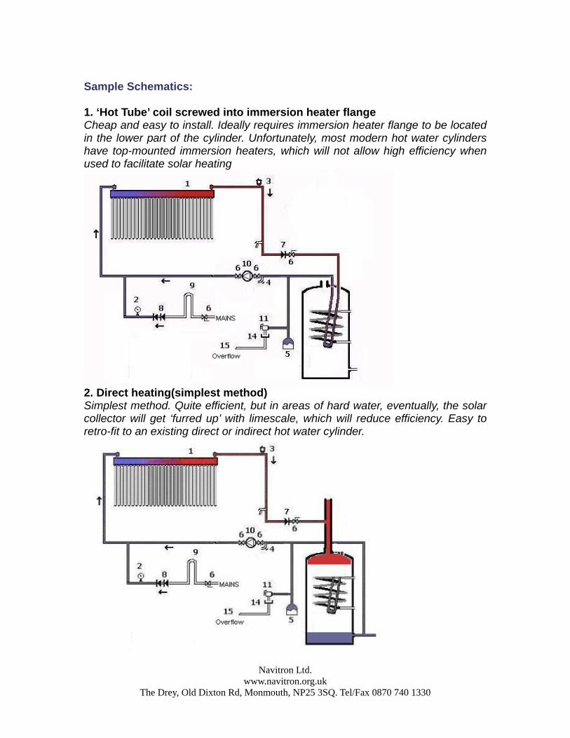
Sample Schematics: 1. ‘Hot Tube’ coil screwed into immersion heater flange Cheap and easy to install. Ideally requires immersion heater flange to be located in the lower part of the cylinder. Unfortunately, most modern hot water cylinders have top-mounted immersion heaters, which will not allow high efficiency when used to facilitate solar heating
2. Direct heating(simplest method) Simplest method. Quite efficient, but in areas of hard water, eventually, the solar collector will get ‘furred up’ with limescale, which will reduce efficiency. Easy to retro-fit to an existing direct or indirect hot water cylinder.
Navitron Ltd. www.navitron.org.uk
The Drey, Old Dixton Rd, Monmouth, NP25 3SQ. Tel/Fax 0870 740 1330
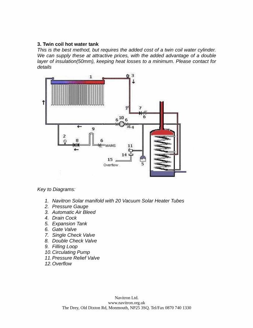
3. Twin coil hot water tank This is the best method, but requires the added cost of a twin coil water cylinder. We can supply these at attractive prices, with the added advantage of a double layer of insulation(50mm), keeping heat losses to a minimum. Please contact for details
Key to Diagrams:
1. Navitron Solar manifold with 20 Vacuum Solar Heater Tubes 2. Pressure Gauge 3. Automatic Air Bleed 4. Drain Cock 5. Expansion Tank 6. Gate Valve 7. Single Check Valve 8. Double Check Valve 9. Filling Loop 10. Circulating Pump 11. Pressure Relief Valve 12. Overflow
Navitron Ltd. www.navitron.org.uk
The Drey, Old Dixton Rd, Monmouth, NP25 3SQ. Tel/Fax 0870 740 1330