powerref 3 - plusoptix r09 binocular pupillometer ... · page 1 of 34 powerref 3 - plusoptix r09...
TRANSCRIPT
Page 1 of 34
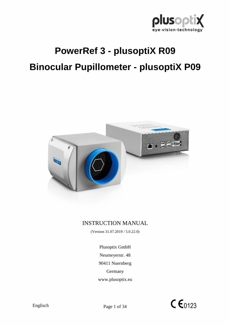
PowerRef 3 - plusoptiX R09
Binocular Pupillometer - plusoptiX P09
INSTRUCTION MANUAL
(Version 31.07.2019 / 5.0.22.0)
Plusoptix GmbH
Neumeyerstr. 48
90411 Nuernberg
Germany
www.plusoptix.eu
Englisch
Page 2 of 34
Table of contents
1. Safety instructions ........................................................................................ 4
1.1 Warning and Symbols ................................................................................................. 4 1.2 Handling of the plusoptiX R09 .................................................................................... 5
1.3 Exclusive use of the plusoptiX R09 ............................................................................ 5 1.4 Operation of the plusoptiX R09 ................................................................................... 5 1.5 Duties of the operator .................................................................................................. 5
2. Delivery ....................................................................................................... 6
2.1 Storage ......................................................................................................................... 7 2.2 Unpacking .................................................................................................................... 7
2.3 Setting up ..................................................................................................................... 7
3. Connecting and switching on the system .................................................... 8
3.1 Connection ................................................................................................................... 8
3.2 Switching on the system .............................................................................................. 8
4. Settings ....................................................................................................... 11
4.1 General (Basic settings) ............................................................................................. 11 4.2 System ....................................................................................................................... 12
5. Measurement procedure ............................................................................. 13
5.1 Measurement procedure predefined Measurement Routine ...................................... 13 5.2 Documentation Logfile .............................................................................................. 18
5.3 Viewing the video of the last measurement ............................................................... 19 5.4 Storing a video ........................................................................................................... 19
5.5 Loading a video ......................................................................................................... 20
6. Predefined measurement routines .............................................................. 21
6.1 Graphical output ........................................................................................................ 21
7. How to create your own Measurement routines ........................................ 24
7.1 How does it work? ..................................................................................................... 24 7.2 Using qemacs ............................................................................................................. 24
7.3 Create the command set for the measurement ........................................................... 24 7.4 Example: Standart_10sec.pox ................................................................................... 25
7.5 Link the graphical output with the measurement routine .......................................... 25
8. Logging external events ............................................................................. 26
8.1 How does it work? ..................................................................................................... 26 8.2 How to install? ........................................................................................................... 26
9. Remote control ........................................................................................... 27
10. Switching off the system ............................................................................ 28
Page 3 of 34
11. Measurement setup ........................................................................................ 28
12. Warranty ........................................................................................................ 29
13. Service and maintenance ........................................................................... 29
13.1 Service ....................................................................................................................... 29 13.2 Maintenance ............................................................................................................... 30
14. Practical tips .................................................................................................. 30
14.1 Measurement results .................................................................................................. 30 14.2 Troubleshooting ......................................................................................................... 31
15. Specifications ................................................................................................ 32
Page 4 of 34
0123
1. Safety instructions
Please read all of the instructions in this manual by all means in order to avoid any
danger to life and health, to achieve reliable measurement results and to obtain the
device in good working conditions.
1.1 Warning and Symbols
ATTENTION: This symbol is intended to advise the user of the presence of
important operating or maintenance requirements.
Service or repair to be performed by qualified authorized personnel only.
There are no user serviceable parts inside the instrument. Opening this
device can expose the user to harmful invisible electrical shock.
Note: Disassembly of plusoptiX R09 device will void the warranty. Refer
all servicing to Plusoptix authorized service representatives listed in
the section Service and Maintenance (Chapter 11).
Do not sterilize the plusoptiX R09 device or any of the components.
CAUTION: Use of controls or adjustments or performance of procedures
other than those specified herein may result in wrong
measurements.
The CE mark on this device indicates that it has been tested and conforms
to the provisions noted within the 2007/47/EG Medical Device Directive.
At the end of life time (electronic waste).
ESD sensitive device: Discharge human body by touching a grounded plane
or use ground strips before installation or touching the connectors.
This symbol shows that this product keeps the requirements for an
application part type B of EN 60601-1.
Page 5 of 34
1.2 Handling of the plusoptiX R09
The plusoptiX R09 is an optical electronic measuring device. The construction and
functionality of the plusoptiX R09 is very similar of a video camera / camcorder. So,
please handle the device as carefully as you would use your own camcorder. If you
follow this advice, the plusoptiX R09 will last you for many years without any trouble.
1.3 Exclusive use of the plusoptiX R09
The exclusive use the plusoptiX R09 device is to measure dynamic refractive data,
asymmetry of the corneal reflexes, pupil size and pupil distance in real time. Both eyes
are measured at the same time (binocular) from one meter (3.3 ft) away from the
patient.
Note: The measurement is from one meter distance to the patient and so +1.00 dpt
accommodation is included into the measurement result.
This measurement setup should only be used for research purposes. Also it
should only be used by trained persons.
1.4 Operation of the plusoptiX R09
Check all cable connections from the mains as well as the VGA cable
between the plusoptiX R09 device and the monitor. Be sure the keyboard
and the mouse is switched on.
Make sure that any cables or connectors which show any damage are
replaced before switching on the plusoptiX R09 system.
Use only the delivered power adapter and the delivered cables.
The plusoptiX S09 complies with the requirements of the directive of medical devices
2007/47/EG.
1.5 Duties of the operator
The operator must ensure that only personnel who have been trained in handling of the
plusoptiX R09 are permitted to operate the system. All users must read the operating
manual and take note of the safety instructions and provisions.
Note: Training courses on the operation of the plusoptiX R09 subject to safety notes
and provisions for medical products are available on request.
Do not connect systems other than those supplied by Plusoptix.
Page 6 of 34
2. Delivery
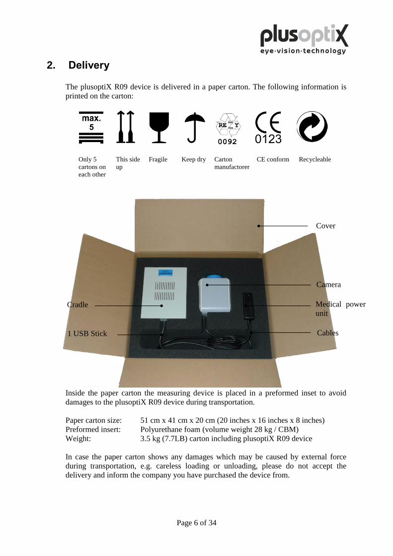
The plusoptiX R09 device is delivered in a paper carton. The following information is
printed on the carton:
Only 5
cartons on
each other
This side
up
Fragile Keep dry Carton
manufactorer
CE conform Recycleable
Inside the paper carton the measuring device is placed in a preformed inset to avoid
damages to the plusoptiX R09 device during transportation.
Paper carton size: 51 cm x 41 cm x 20 cm (20 inches x 16 inches x 8 inches)
Preformed insert: Polyurethane foam (volume weight 28 kg / CBM)
Weight: 3.5 kg (7.7LB) carton including plusoptiX R09 device
In case the paper carton shows any damages which may be caused by external force
during transportation, e.g. careless loading or unloading, please do not accept the
delivery and inform the company you have purchased the device from.
Cradle
Cover
Camera
Medical power
unit
Cables 1 USB Stick
Page 7 of 34
2.1 Storage
The plusoptiX R09 device can be stored in the original package when the storage room
fulfils the following requirements:
Temperature: 0°C to +50°C (32°F to 122°F)
Humidity: 10% to 85% (no condensation)
Keep the plusoptiX R09 device away from any heat source.
2.2 Unpacking
Open the carton only in position „This side up“.
After unpacking the plusoptiX R09 please check that all items are delivered which are
listed on the delivery note. Missing items can only be replaced when a claim has been
forwarded to the company you have the device purchased from within one week after
accepting the delivery.
Note: Please keep the original packing material in case later transportation may be
required.
Do not store the packing material in a room with an open fire place.
2.3 Setting up
When you set up the plusoptiX R09 make sure that no cable can be reached by
Probands.
Protect the plusoptiX R09 from direct sunlight.
Page 8 of 34
3. Connecting and switching on the system
3.1 Connection
For operation, the plusoptiX R09 must be connected to a monitor and keyboard with a
mouse. The monitor must fulfill the following system requirements:
Resolution: 1024 x 768 pixels
Interface: VGA
Four (4) USB ports of type A are available on the plusoptiX R09 for connecting e.g.
keyboard, mouse or USB-sticks.
Where a monitor is already available at a workstation, a switch (Monitor Switch TK 207
by “Trendnet”) can be used to connect this monitor to the plusoptiX R09. This allows
you to save space by using the monitor for the plusoptiX R09.
Connect the VGA cable from the monitor to the plusoptiX R09. The keyboard and
mouse can be connected to the plusoptiX R09 by means of a USB cable or a wireless
USB adapter. Attach the 12V DC connector to the plusoptiX R09 and the medical
power unit to a 110 – 220 V AC (50 – 60 Hz) power plug. Ensure that the power plug is
switched off after close of business. This is a precaution in case a short-circuit occurs
during night-time which may cause a fire.
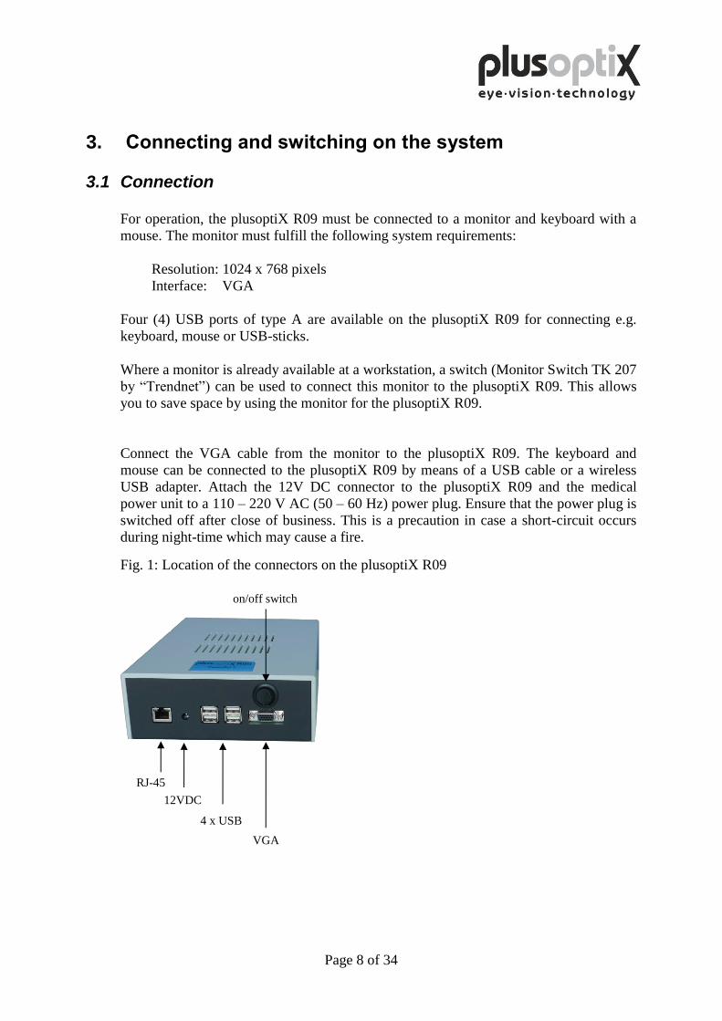
Fig. 1: Location of the connectors on the plusoptiX R09
on/off switch
4 x USB
VGA
12VDC
RJ-45
Page 9 of 34
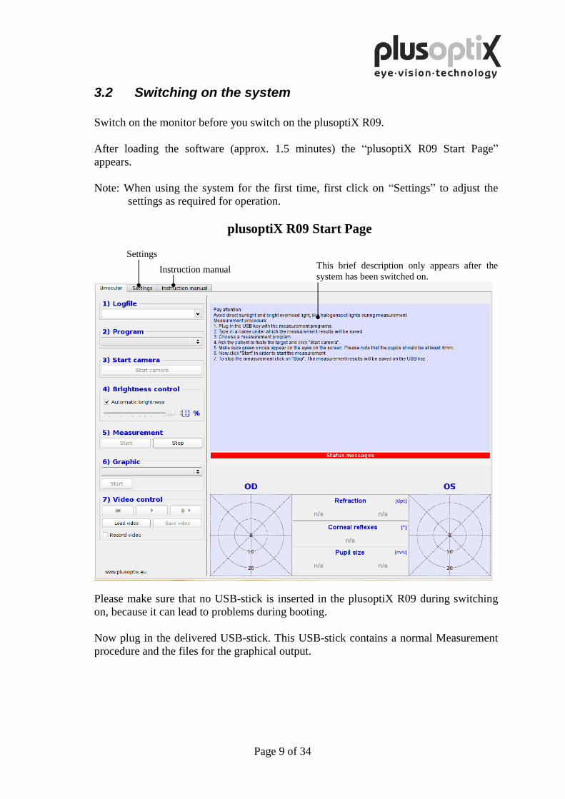
3.2 Switching on the system
Switch on the monitor before you switch on the plusoptiX R09.
After loading the software (approx. 1.5 minutes) the “plusoptiX R09 Start Page”
appears.
Note: When using the system for the first time, first click on “Settings” to adjust the
settings as required for operation.
plusoptiX R09 Start Page
This brief description only appears after the
system has been switched on.
Please make sure that no USB-stick is inserted in the plusoptiX R09 during switching
on, because it can lead to problems during booting.
Now plug in the delivered USB-stick. This USB-stick contains a normal Measurement
procedure and the files for the graphical output.
Settings
Instruction manual
Page 10 of 34
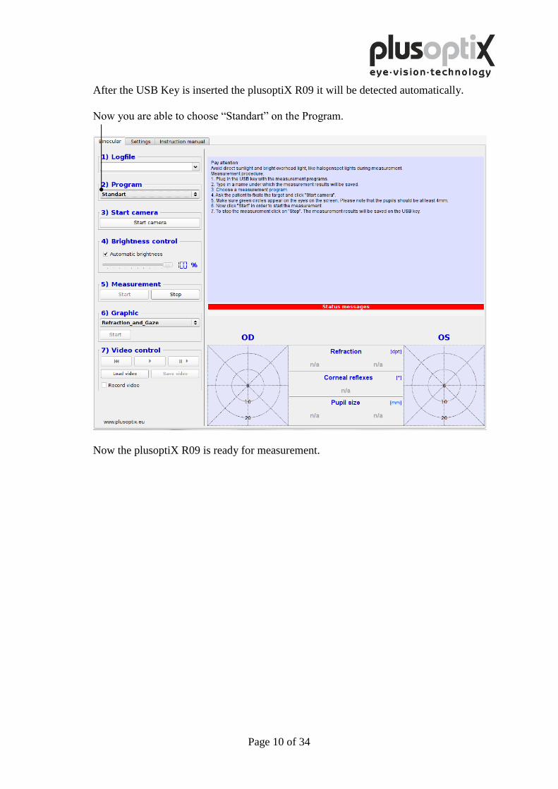
After the USB Key is inserted the plusoptiX R09 it will be detected automatically.
Now you are able to choose “Standart” on the Program.
Now the plusoptiX R09 is ready for measurement.
Page 11 of 34
4. Settings
For the first start-up it is recommended to adapt settings e.g. general (basic settings),
system to your custom conditions. With the exception of the general settings appears at
the “System” page a security query, where you have to type in “YES”, to perform
settings if you are authorized to do that. If you are not authorized click on “Cancel”.
Then you just can have a look at the existing settings and not perform any settings.
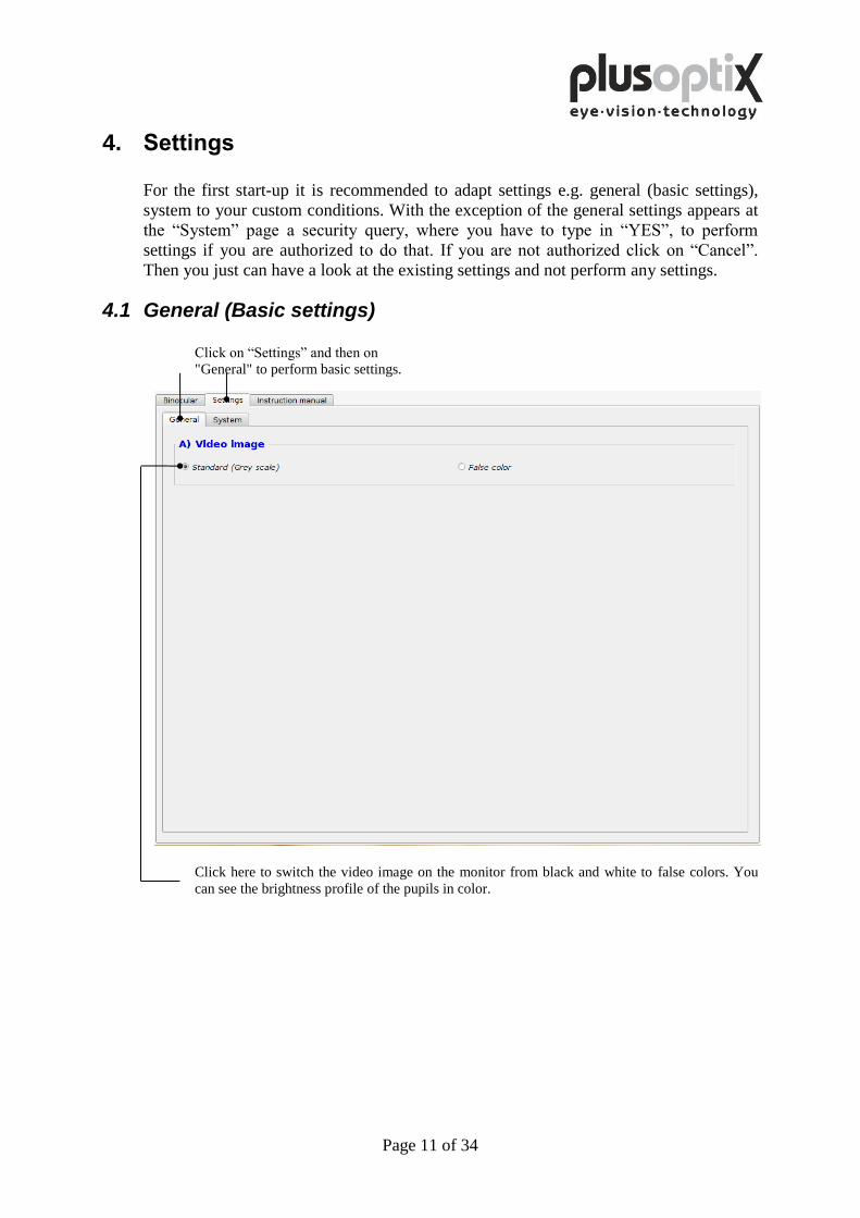
4.1 General (Basic settings)
Click on “Settings” and then on
"General" to perform basic settings.
Click here to switch the video image on the monitor from black and white to false colors. You
can see the brightness profile of the pupils in color.
Page 12 of 34
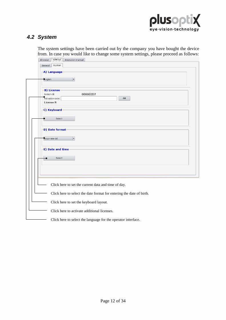
4.2 System
The system settings have been carried out by the company you have bought the device
from. In case you would like to change some system settings, please proceed as follows:
Click here to set the current data and time of day.
Click here to select the date format for entering the date of birth.
Click here to set the keyboard layout.
Click here to activate additional licenses.
Click here to select the language for the operator interface.
Page 13 of 34
5. Measurement procedure
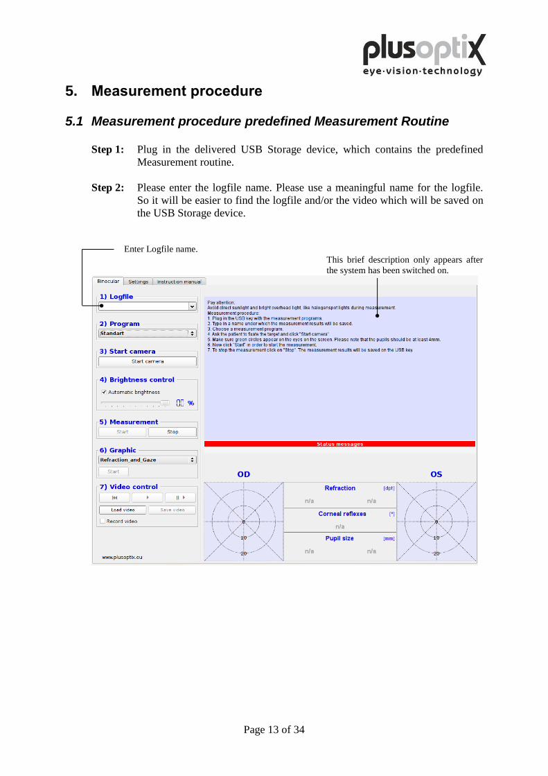
5.1 Measurement procedure predefined Measurement Routine
Step 1: Plug in the delivered USB Storage device, which contains the predefined
Measurement routine.
Step 2: Please enter the logfile name. Please use a meaningful name for the logfile.
So it will be easier to find the logfile and/or the video which will be saved on
the USB Storage device.
Enter Logfile name.
This brief description only appears after
the system has been switched on.
Page 14 of 34
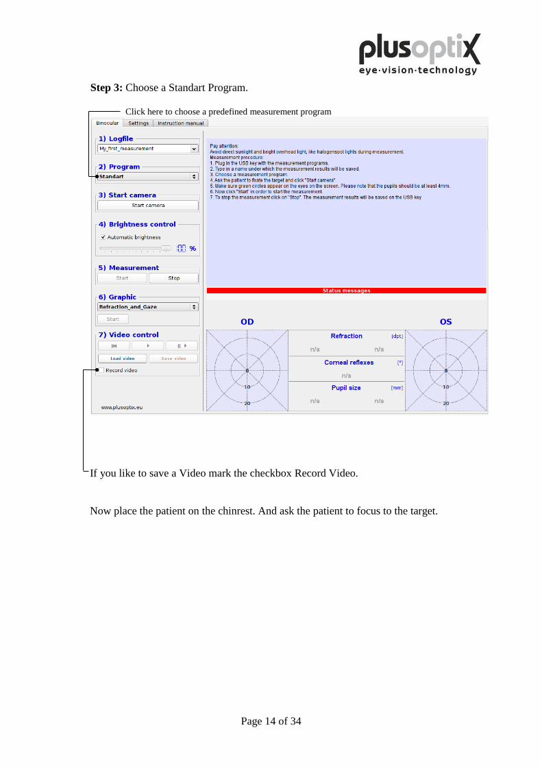
Step 3: Choose a Standart Program.
Click here to choose a predefined measurement program
If you like to save a Video mark the checkbox Record Video.
Now place the patient on the chinrest. And ask the patient to focus to the target.
Page 15 of 34
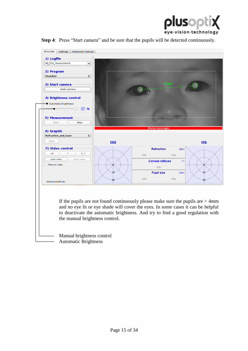
Step 4: Press “Start camera” and be sure that the pupils will be detected continuously.
If the pupils are not found continuously please make sure the pupils are > 4mm
and no eye lit or eye shade will cover the eyes. In some cases it can be helpful
to deactivate the automatic brightness. And try to find a good regulation with
the manual brightness control.
Manual brightness control
Automatic Brightness
Page 16 of 34
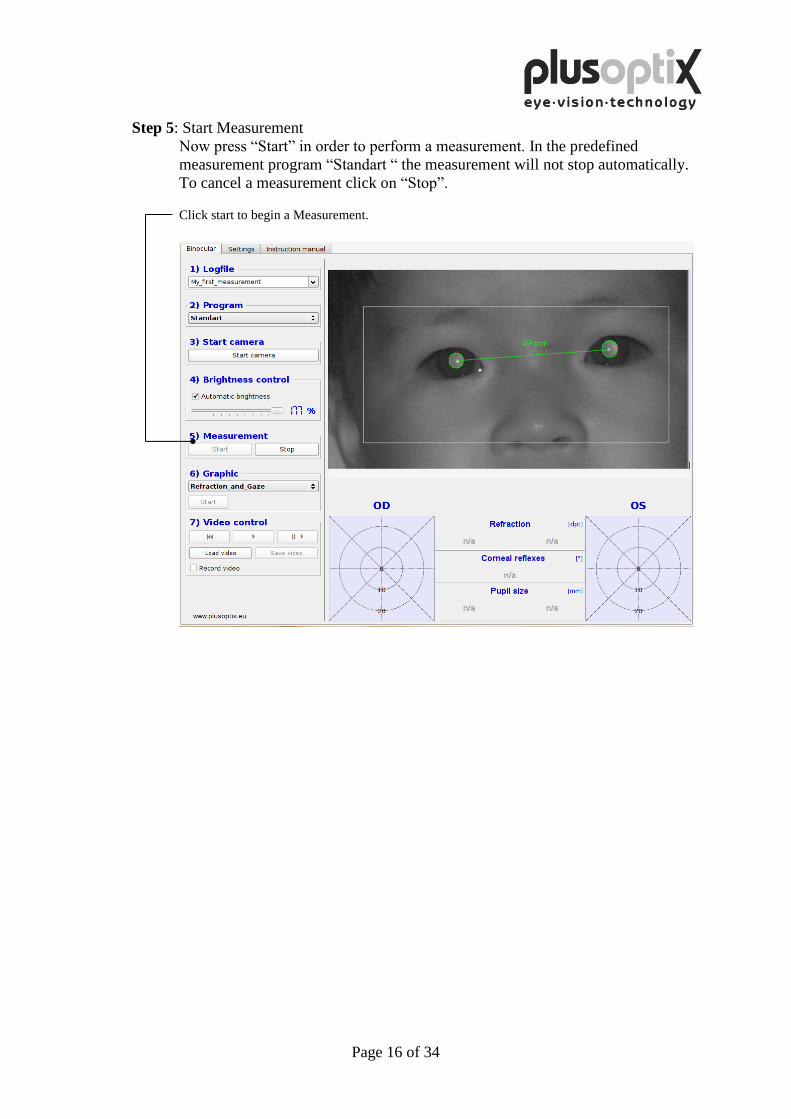
Step 5: Start Measurement
Now press “Start” in order to perform a measurement. In the predefined
measurement program “Standart “ the measurement will not stop automatically.
To cancel a measurement click on “Stop”.
Click start to begin a Measurement.
Page 17 of 34
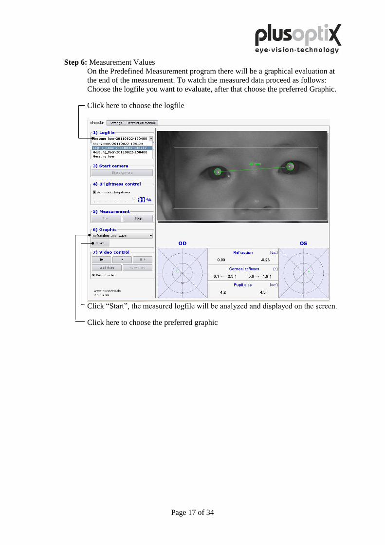
Step 6: Measurement Values
On the Predefined Measurement program there will be a graphical evaluation at
the end of the measurement. To watch the measured data proceed as follows:
Choose the logfile you want to evaluate, after that choose the preferred Graphic.
Click here to choose the logfile
Click “Start”, the measured logfile will be analyzed and displayed on the screen.
Click here to choose the preferred graphic
Page 18 of 34
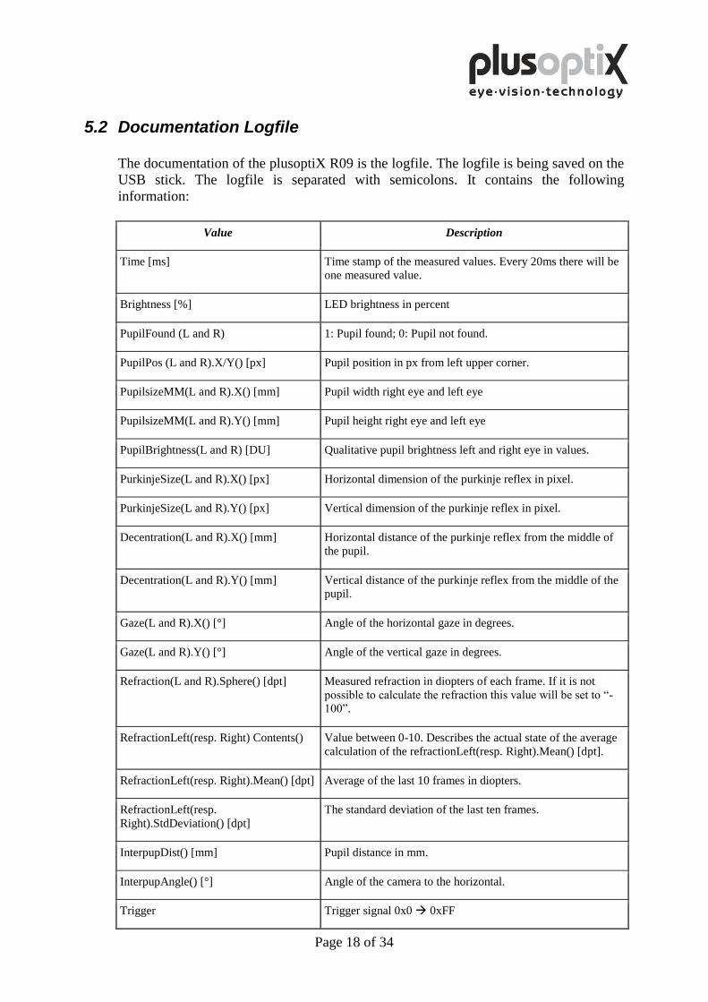
5.2 Documentation Logfile
The documentation of the plusoptiX R09 is the logfile. The logfile is being saved on the
USB stick. The logfile is separated with semicolons. It contains the following
information:
Value Description
Time [ms] Time stamp of the measured values. Every 20ms there will be
one measured value.
Brightness [%] LED brightness in percent
PupilFound (L and R) 1: Pupil found; 0: Pupil not found.
PupilPos (L and R).X/Y() [px] Pupil position in px from left upper corner.
PupilsizeMM(L and R).X() [mm] Pupil width right eye and left eye
PupilsizeMM(L and R).Y() [mm] Pupil height right eye and left eye
PupilBrightness(L and R) [DU] Qualitative pupil brightness left and right eye in values.
PurkinjeSize(L and R).X() [px] Horizontal dimension of the purkinje reflex in pixel.
PurkinjeSize(L and R).Y() [px] Vertical dimension of the purkinje reflex in pixel.
Decentration(L and R).X() [mm] Horizontal distance of the purkinje reflex from the middle of
the pupil.
Decentration(L and R).Y() [mm] Vertical distance of the purkinje reflex from the middle of the
pupil.
Gaze(L and R).X() [°] Angle of the horizontal gaze in degrees.
Gaze(L and R).Y() [°] Angle of the vertical gaze in degrees.
Refraction(L and R).Sphere() [dpt] Measured refraction in diopters of each frame. If it is not
possible to calculate the refraction this value will be set to “-
100”.
RefractionLeft(resp. Right) Contents() Value between 0-10. Describes the actual state of the average
calculation of the refractionLeft(resp. Right).Mean() [dpt].
RefractionLeft(resp. Right).Mean() [dpt] Average of the last 10 frames in diopters.
RefractionLeft(resp.
Right).StdDeviation() [dpt]
The standard deviation of the last ten frames.
InterpupDist() [mm] Pupil distance in mm.
InterpupAngle() [°] Angle of the camera to the horizontal.
Trigger Trigger signal 0x0 0xFF
Page 19 of 34
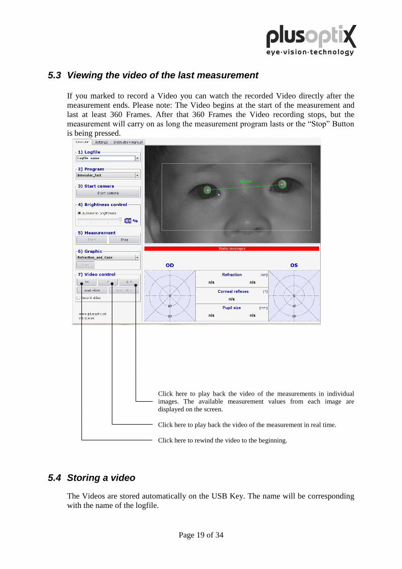
5.3 Viewing the video of the last measurement
If you marked to record a Video you can watch the recorded Video directly after the
measurement ends. Please note: The Video begins at the start of the measurement and
last at least 360 Frames. After that 360 Frames the Video recording stops, but the
measurement will carry on as long the measurement program lasts or the “Stop” Button
is being pressed.
Click here to play back the video of the measurements in individual
images. The available measurement values from each image are
displayed on the screen.
Click here to play back the video of the measurement in real time.
Click here to rewind the video to the beginning.
5.4 Storing a video
The Videos are stored automatically on the USB Key. The name will be corresponding
with the name of the logfile.
Page 20 of 34
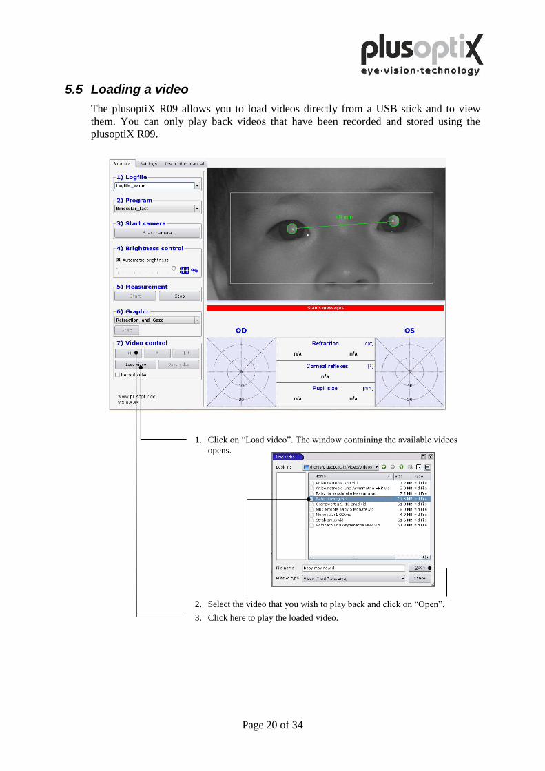
5.5 Loading a video
The plusoptiX R09 allows you to load videos directly from a USB stick and to view
them. You can only play back videos that have been recorded and stored using the
plusoptiX R09.
1. Click on “Load video”. The window containing the available videos
opens.
2. Select the video that you wish to play back and click on “Open”.
3. Click here to play the loaded video.
Page 21 of 34
6. Predefined measurement routines On the delivered USB key there are two predefined Measurement Routines. Here is a summary how
they will work.
Program Description Standart This is the measurement which is described in the measurement procedure.
Standart_10_sec The measurement will start by pressing the Start button. It will last 10 sec. After that time it will stop automatically.
6.1 Graphical output
The graphical output bases on Gnuplot. This is powerful Open Source Tool. So in that manual
only a short explanation is given on an example file. For nearer information about gnuplot
please refer to http://www.gnuplot.info/
The Graphical output shows the Measurement results which are stored in the logfile which
will be created on the USB Storage. The logfiles can also be imported in any other statistical
tool. This output is to check whether the measurement has worked or not.
The graphical output files on the USB Key are:
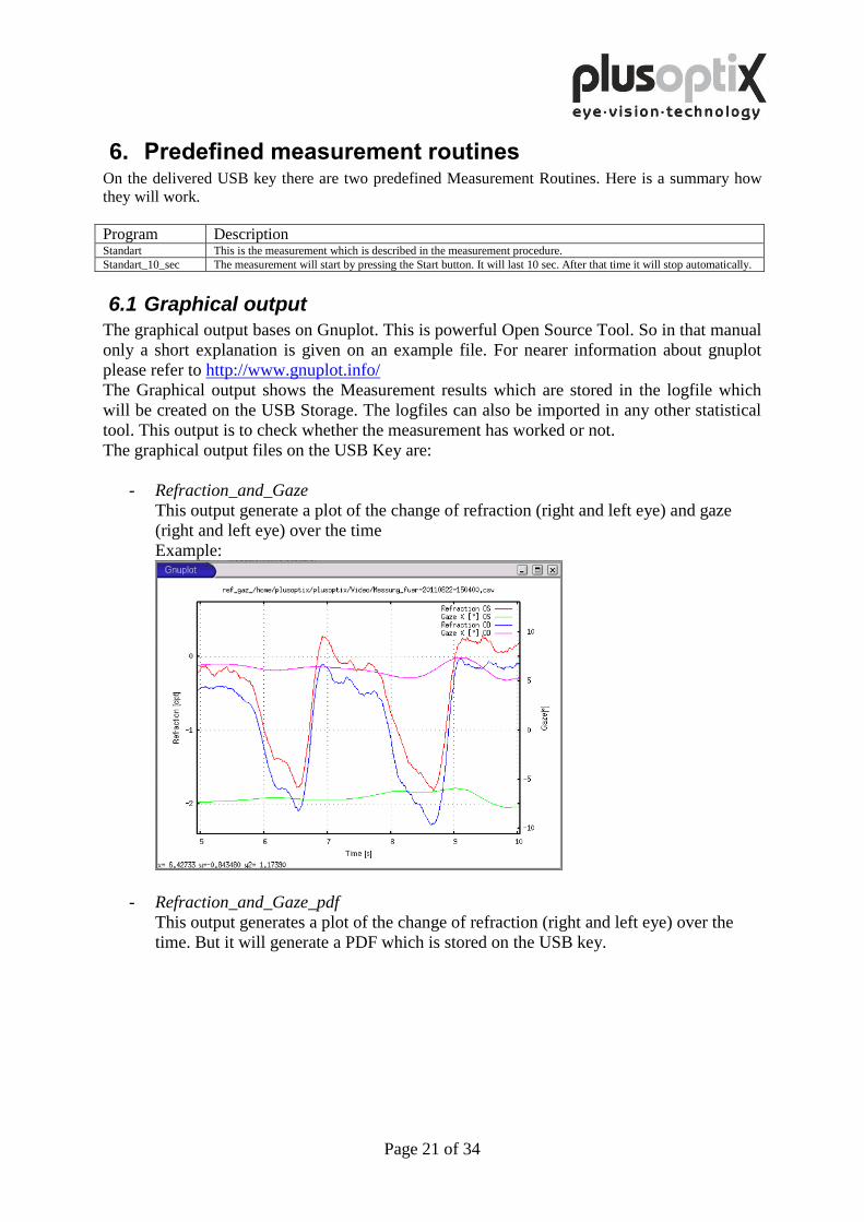
- Refraction_and_Gaze
This output generate a plot of the change of refraction (right and left eye) and gaze
(right and left eye) over the time
Example:
- Refraction_and_Gaze_pdf
This output generates a plot of the change of refraction (right and left eye) over the
time. But it will generate a PDF which is stored on the USB key.
Page 22 of 34
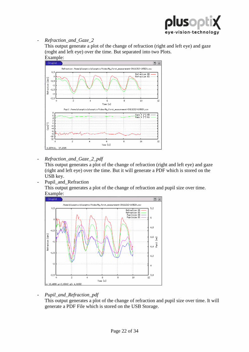
- Refraction_and_Gaze_2
This output generate a plot of the change of refraction (right and left eye) and gaze
(roght and left eye) over the time. But separated into two Plots.
Example:
- Refraction_and_Gaze_2_pdf
This output generates a plot of the change of refraction (right and left eye) and gaze
(right and left eye) over the time. But it will generate a PDF which is stored on the
USB key.
- Pupil_and_Refraction
This output generates a plot of the change of refraction and pupil size over time.
Example:
- Pupil_and_Refraction_pdf
This output generates a plot of the change of refraction and pupil size over time. It will
generate a PDF File which is stored on the USB Storage.
Page 23 of 34
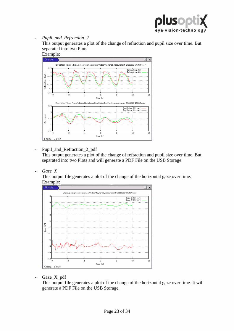
- Pupil_and_Refraction_2
This output generates a plot of the change of refraction and pupil size over time. But
separated into two Plots
Example:
- Pupil_and_Refraction_2_pdf
This output generates a plot of the change of refraction and pupil size over time. But
separated into two Plots and will generate a PDF File on the USB Storage.
- Gaze_X
This output file generates a plot of the change of the horizontal gaze over time.
Example:
- Gaze_X_pdf
This output file generates a plot of the change of the horizontal gaze over time. It will
generate a PDF File on the USB Storage.
Page 24 of 34
7. How to create your own Measurement routines In this section the creation of measurement routines is being described. To create
Measurement routines, you will need a Text editor. There is a text editor on the plusoptiX
R09 installed, too. All scripts which already installed are written with this editor.
7.1 How does it work?
The measurement routines have to be stored on the USB Key. After plugged in the USB Key
it will be automatically mounted to the directory /home/plusoptix/plusoptix/Video/.
On this USB key the device looks for a special file which contain the control of the
measurement.
7.2 Using qemacs
The Editor on the system is qemacs. Here are the basic steps described which are needed to
create new files and edit existing files. But qemacs is a very powerful tool. If you need some
more help using qemacs please refer to http://bellard.org/qemacs/qe-doc.html.
Here are the basic steps:
Step 1: Press “ALT” + “F8” simultaneously. A “Service Menu” appears
Step 2: Choose “Xterm”. A command window will open. This is a linux bash shell.
Step 3: Type in cd /home/plusoptix/plusoptix/Video followed by enter to change the directory to the
plugged USB Key.
Step 4: To create a new file type in qemacs <newfile.xxx>, to edit an existing file type in qemacs
<existingfile.xxx>.
Step 5: After editing press “Ctrl-x Ctrl-s” to save the changes.
Step 6: You can close this file with “Ctrl-x Ctrl-c”.
7.3 Create the command set for the measurement
The *.pox file is the control file of the measurement.
The known instructions are in the following table:
Instruction Meaning Notes #<comment> Comments If a line begins with the # sign all behind this sign is a
comment and is ignored by the measurement program. Please
use it. It makes the measurement program more readable.
+ <button_name> User interaction On this interaction the measurement program waits before it
goes on. So + StartCam waits for clicking the “Start camera”
button on the user interface.
Values for command: StartCam (Button “Start Camera”);
StartMeasure (Button “Start”); StopMeasure (Button “Stop”)
StartCamera Start Camera This command starts the camera. After that command you can
see pictures on the Monitor. But the measurement is not
started yet.
StartMeasure Start of the
measurement
This command starts the measurement. The measured values
will be directly transferred to the logfile.
StopGrabbing Stop of
measurement.
This command stops the Measurement.
Send
<command>
Send an
instruction
This instruction sends a command directly to the motor
control. There will be no answer back or is being ignored.
delay <time in
ms>
waits until the
next send
command
This instruction changes the time between the send
commands. It has no effect for the other commands.
Page 25 of 34
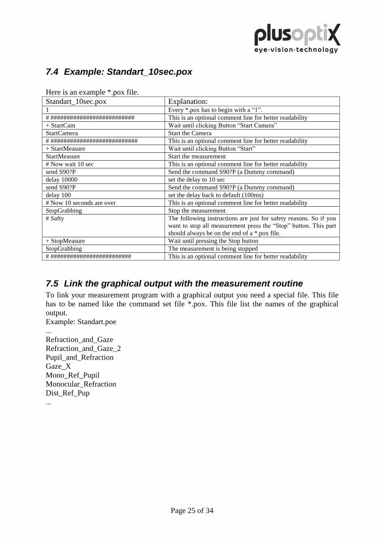
7.4 Example: Standart_10sec.pox
Here is an example *.pox file.
Standart_10sec.pox Explanation: 1 Every *.pox has to begin with a “1”.
# ########################## This is an optional comment line for better readability
+ StartCam Wait until clicking Button “Start Camera”
StartCamera Start the Camera
# ########################### This is an optional comment line for better readability
+ StartMeasure Wait until clicking Button “Start”
StartMeasure Start the measurement
# Now wait 10 sec This is an optional comment line for better readability
send S90?P Send the command S90?P (a Dummy command)
delay 10000 set the delay to 10 sec
send S90?P Send the command S90?P (a Dummy command)
delay 100 set the delay back to default (100ms)
# Now 10 seconds are over This is an optional comment line for better readability
StopGrabbing Stop the measurement
# Safty The following instructions are just for safety reasons. So if you
want to stop all measurement press the “Stop” button. This part
should always be on the end of a *.pox file.
+ StopMeasure Wait until pressing the Stop button
StopGrabbing The measurement is being stopped
# ######################### This is an optional comment line for better readability
7.5 Link the graphical output with the measurement routine
To link your measurement program with a graphical output you need a special file. This file
has to be named like the command set file *.pox. This file list the names of the graphical
output.
Example: Standart.poe
...
Refraction_and_Gaze
Refraction_and_Gaze_2
Pupil_and_Refraction
Gaze_X
Mono_Ref_Pupil
Monocular_Refraction
Dist_Ref_Pup
...
Page 26 of 34
8. Logging external events An optional feature is the logging of external events. This feature can be used to mark up to
256 (0x0 to 0xFF) measurement related events in the log file.
8.1 How does it work?
To activate that feature a USB Key with a support script and an USB Serial Converter from
FTDI is needed. The USB Key Support script is provided by Plusoptix, and the USB Serial
Converter is available from http://www.ftdichip.com/Products/Cables/USBTTLSerial.htm or
a Distributor like Digikey.
Further on a sender of the serial commands is needed. These could be a Computer with a
serial port or an USB Serial Converter, a micro controller or something similar. The serial
port of the sender has to be set to a speed of 115200Baud 8N1. If you use another computer
to send some commands in you will need a “null modem” Cable.
The command is sXX where s is the start message and XX is the byte of the event.
For example: s01 writes a “1” in the trigger column of the log file. It will stay until a new
command is send over the serial port. A new measurement resets the Trigger Colum to “0”.
8.2 How to install?
Switch off the PowerRef3 and remove the provided USB Stick with the measurement
routines.
Plug in the FTDI USB Serial Converter and start the PowerRef 3.
After booting a small Window “Initializing System” will appear.
Now plug in the USB key with the provided support script.
After a little while the Measurement Software starts.
Plug in the USB key with the measurement routines and start a measurement.
Now you can send your events to the PowerRef 3.
Page 27 of 34
9. Remote control To control the PowerRef 3 remotely there is program binary in the delivered measurement
routines called “powerrefcontrol”. The program can control the PowerRef 3 over a command
line (On the Powerref 3 itself or over ssh connection).
To use the program press ALT+F8 and choose Xterm.
Go to the directory Video: cd /home/plusoptix/plusoptix/Video/
The command syntax is:
./powerrefcontrol <COMMAND> [Sleep time in ms <COMMAND]
The valid commands are:
StartCamera This command starts the Camera.
StartMeasurement A Measurement is started a log file is being created.
StopCamera Stops the Measurement and the capturing
Sleep <ms> With this command you could queue the commands
Autobrightness <0|1>:percent Control the Autobrighness Setting
Record <0|1> Starts a recording of 360 Frames
Example:
Start the camera,
wait 5 Seconds to let the brightness control detect the pupils,
start a measurement which lasts 10 seconds.
./powerrefcontrol StartCamera Sleep 5000 StartMeasurement Sleep 10000 StopCamera
Page 28 of 34
10. Switching off the system
First switch off the plusoptiX R09 using the on/off switch, followed by the monitor.
The on/off switch on the plusoptiX R09 flashes after switch-off until the program has
been shut down completely.
At the end of business day the monitor and the medical power unit must be
separated from the power supply or you have to switch off the on/off switch
at the multiple socket outlet. This is a precaution in case a short circuit
occurs during night-time which may cause a fire.
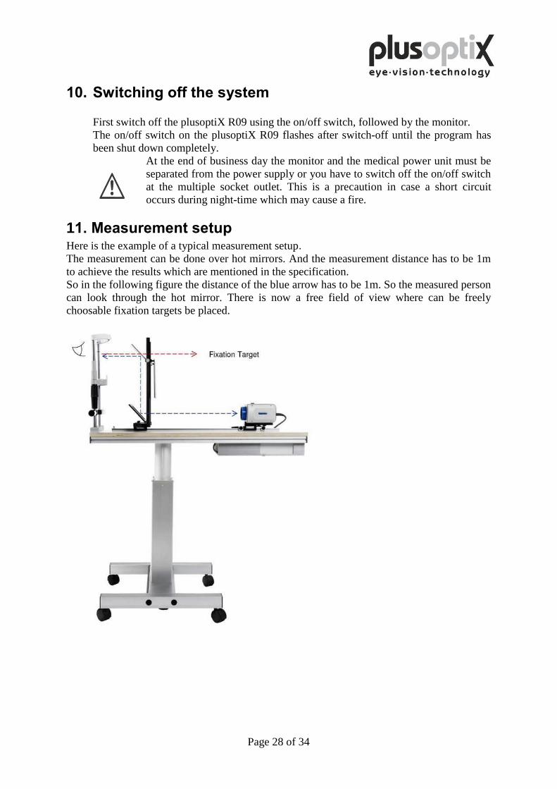
11. Measurement setup Here is the example of a typical measurement setup. The measurement can be done over hot mirrors. And the measurement distance has to be 1m
to achieve the results which are mentioned in the specification.
So in the following figure the distance of the blue arrow has to be 1m. So the measured person
can look through the hot mirror. There is now a free field of view where can be freely
choosable fixation targets be placed.
Page 29 of 34
12. Warranty
The plusoptiX R09 is supplied with a 12-month guarantee, starting from the data of the
delivery note.
All work processes at Plusoptix are included in a quality management system, thus
providing the highest degree of assurance of error-free materials and workmanship.
Should the plusoptiX R09 fail during the guarantee period or the method of operation
not be in accordance with the operating instructions, Plusoptix will repair or exchange
the system at no charge.
The guarantee is only supplied on new systems that have been sold by Plusoptix or an
authorized sales partner of Plusoptix. Systems requiring repair can be returned to the
authorized sales partner from whom the system was purchased. Before you return the
device, please consider the advices in chapter 12.2 Trouble shooting. The customer is
responsible for the transport costs of the system.
Note: A copy of the system delivery note must be included in the transport to ensure the
validity of the guarantee claim.
The guarantee will not be provided on systems that have been damaged externally, and
will be void in its entirety in the event of improper use, cleaning and transport as well as
changes or intervention to the software and usage of the plusoptiX R09 contrary to the
instructions. Claims under guarantee will also be void if the system is opened by
persons not authorized by Plusoptix.
Note: Software updates during the guarantee period are supplied at no charge.
13. Service and maintenance
13.1 Service
For repairs or guarantee services, please send the plusoptiX R09 system in its original
packaging to the company you have bought the device from or to:
Plusoptix GmbH Service
Neumeyerstr. 46
90411 Nuernberg
Germany
Tel.: +49 - 911 - 598 399 - 20
Fax: +49 - 911 - 598 399 - 90
Plusoptix Inc.
2850 Paces Ferry Road
Suite 440
Atlanta, Ga 30339
USA
Tel.: +1 - 800 - 488 - 6436
Note:
- The customer has to bare the transport cost for returning for repair to the company the
device was purchased from or to Plusoptix.
- A copy of the delivery note must be attached to the transport for repair in order to
prove the validity of the guarantee claim.
Page 30 of 34
13.2 Maintenance
The plusoptiX R09 is maintenance-free. It is recommended that the system be covered
with a cloth when not being used. Use only a lightly moist microfibre cloth to clean the
system.
1. Do not use sprays, alcohol or other liquids to clean the plusoptiX R09.
2. Please use only a lightly moist microfibre cloth with a little cleaning
liquid to clean the front panel of the system.
14. Practical tips
14.1 Measurement results
1. Measurement range
The measurement range of the plusoptiX R09 is between -7.00 dpt and +5.00 dpt and
is based on the spherical equivalent of the measurement result. This measurement
range can be extended by a max. ± 3.00 dpt by using flippers with plus or minus
lenses.
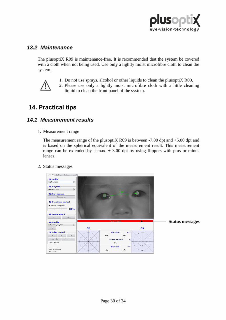
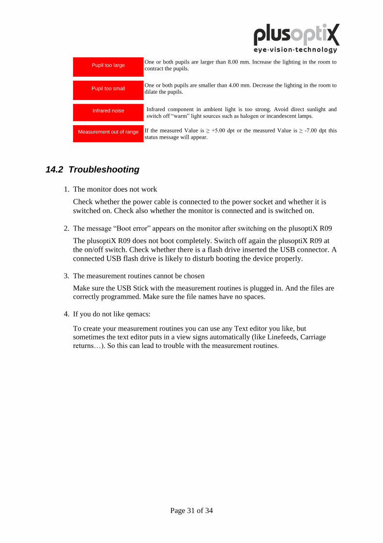
2. Status messages
Status messages
Page 31 of 34
Pupil too large One or both pupils are larger than 8.00 mm. Increase the lighting in the room to contract the pupils.
Pupil too small One or both pupils are smaller than 4.00 mm. Decrease the lighting in the room to dilate the pupils.
Infrared noise Infrared component in ambient light is too strong. Avoid direct sunlight and
switch off “warm” light sources such as halogen or incandescent lamps.
Measurement out of range If the measured Value is ≥ +5.00 dpt or the measured Value is ≥ -7.00 dpt this
status message will appear.
14.2 Troubleshooting
1. The monitor does not work
Check whether the power cable is connected to the power socket and whether it is
switched on. Check also whether the monitor is connected and is switched on.
2. The message “Boot error” appears on the monitor after switching on the plusoptiX R09
The plusoptiX R09 does not boot completely. Switch off again the plusoptiX R09 at
the on/off switch. Check whether there is a flash drive inserted the USB connector. A
connected USB flash drive is likely to disturb booting the device properly.
3. The measurement routines cannot be chosen
Make sure the USB Stick with the measurement routines is plugged in. And the files are
correctly programmed. Make sure the file names have no spaces.
4. If you do not like qemacs:
To create your measurement routines you can use any Text editor you like, but
sometimes the text editor puts in a view signs automatically (like Linefeeds, Carriage
returns…). So this can lead to trouble with the measurement routines.
Page 32 of 34
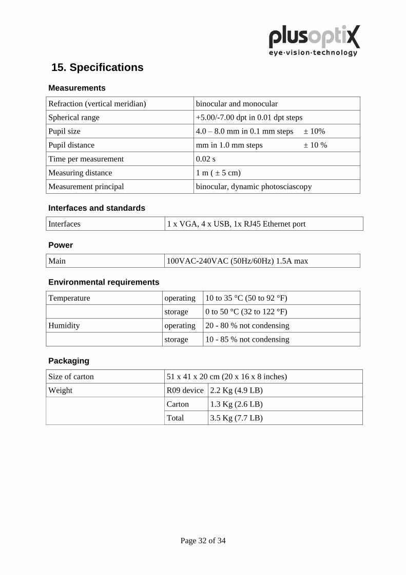
15. Specifications
Measurements
Refraction (vertical meridian) binocular and monocular
Spherical range +5.00/-7.00 dpt in 0.01 dpt steps
Pupil size 4.0 – 8.0 mm in 0.1 mm steps ± 10%
Pupil distance mm in 1.0 mm steps ± 10 %
Time per measurement 0.02 s
Measuring distance 1 m ( ± 5 cm)
Measurement principal binocular, dynamic photosciascopy
Interfaces and standards
Interfaces 1 x VGA, 4 x USB, 1x RJ45 Ethernet port
Power
Main 100VAC-240VAC (50Hz/60Hz) 1.5A max
Environmental requirements
Temperature operating 10 to 35 °C (50 to 92 °F)
storage 0 to 50 °C (32 to 122 °F)
Humidity operating 20 - 80 % not condensing
storage 10 - 85 % not condensing
Packaging
Size of carton 51 x 41 x 20 cm (20 x 16 x 8 inches)
Weight R09 device 2.2 Kg (4.9 LB)
Carton 1.3 Kg (2.6 LB)
Total 3.5 Kg (7.7 LB)
Page 33 of 34
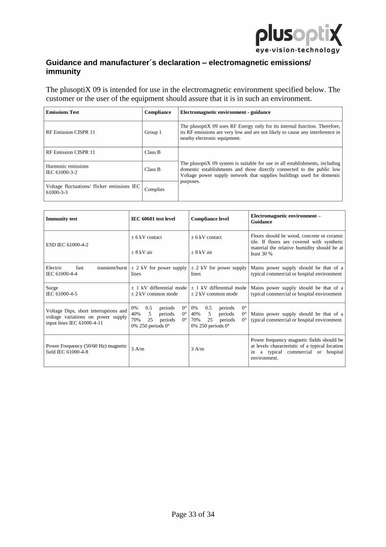
Guidance and manufacturer´s declaration – electromagnetic emissions/ immunity
The plusoptiX 09 is intended for use in the electromagnetic environment specified below. The
customer or the user of the equipment should assure that it is in such an environment.
Emissions Test Compliance Electromagnetic environment - guidance
RF Emission CISPR 11 Group 1 The plusoptiX 09 uses RF Energy only for its internal function. Therefore,
its RF emissions are very low and are not likely to cause any interference in nearby electronic equipment.
RF Emission CISPR 11 Class B
The plusoptiX 09 system is suitable for use in all establishments, including
domestic establishments and those directly connected to the public low Voltage power supply network that supplies buildings used for domestic
purposes.
Harmonic emissions
IEC 61000-3-2 Class B
Voltage fluctuations/ flicker emissions IEC
61000-3-3 Complies
Immunity test IEC 60601 test level Compliance level Electromagnetic environment –
Guidance
ESD IEC 61000-4-2 ± 6 kV contact
± 8 kV air
± 6 kV contact
± 8 kV air
Floors should be wood, concrete or ceramic tile. If floors are covered with synthetic
material the relative humidity should be at
least 30 %
Electric fast transient/burst
IEC 61000-4-4 ± 2 kV for power supply
lines ± 2 kV for power supply
lines Mains power supply should be that of a
typical commercial or hospital environment
Surge
IEC 61000-4-5 ± 1 kV differential mode
± 2 kV common mode ± 1 kV differential mode
± 2 kV common mode Mains power supply should be that of a
typical commercial or hospital environment
Voltage Dips, short interruptions and
voltage variations on power supply
input lines IEC 61000-4-11
0% 0.5 periods 0°
40% 5 periods 0° 70% 25 periods 0°
0% 250 periods 0°
0% 0.5 periods 0°
40% 5 periods 0° 70% 25 periods 0°
0% 250 periods 0°
Mains power supply should be that of a typical commercial or hospital environment
Power Frequency (50/60 Hz) magnetic
field IEC 61000-4-8 3 A/m 3 A/m
Power frequency magnetic fields should be at levels characteristic of a typical location
in a typical commercial or hospital
environment.
Page 34 of 34
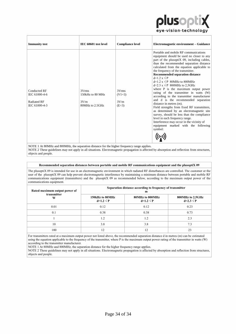
Immunity test IEC 60601 test level Compliance level Electromagnetic environment – Guidance
Conducted RF
IEC 61000-4-6
Radiated RF
IEC 61000-4-3
3Vrms
150kHz to 80 MHz
3V/m
80MHz to 2.5GHz
3Vrms
(V1=3)
3V/m
(E=3)
Portable and mobile RF communications
equipment should be used no closer to any
part of the plusoptiX 09, including cables, than the recommended separation distance
calculated from the equation applicable to
the frequency of the transmitter.
Recommended separation distance d=1.2 x √ P
d=1.2 x √ P 80MHz to 800MHz d=2.3 x √ P 800MHz to 2,5GHz
where P is the maximum output power
rating of the transmitter in watts (W) according to the transmitter manufacturer
and d is the recommended separation
distance in metres (m). Field strengths from fixed RF transmitters,
as determined by an electromagnetic site
survey, should be less than the compliance level in each frequency range.
Interference may occur in the vicinity of
equipment marked with the following symbol:
NOTE 1 At 80MHz and 800MHz, the separation distance for the higher frequency range applies. NOTE 2 These guidelines may not apply in all situations. Electromagnetic propagation is affected by absorption and reflection from structures,
objects and people.
Recommended separation distances between portable and mobile RF communications equipment and the plusoptiX 09
The plusoptiX 09 is intended for use in an electromagnetic environment in which radiated RF disturbances are controlled. The customer or the
user of the plusoptiX 09 can help prevent electromagnetic interference by maintaining a minimum distance between portable and mobile RF
communications equipment (transmitters) and the plusoptiX 09 as recommended below, according to the maximum output power of the communications equipment.
Rated maximum output power of
transmitter
W
Separation distance according to frequency of transmitter
m
150kHz to 80MHz
d=1.2 √ P
80MHz to 800MHz
d=1.2 √ P
800MHz to 2,5GHz
d=2.3 √ P
0.01 0.12 0.12 0.23
0.1 0.38 0.38 0.73
1 1.2 1.2 2.3
10 3.8 3.8 7.3
100 12 12 23
For transmitters rated at a maximum output power not listed above, the recommended separation distance d in metres (m) can be estimated using the equation applicable to the frequency of the transmitter, where P is the maximum output power rating of the transmitter in watts (W)
according to the transmitter manufacturer.
NOTE 1 At 80MHz and 800MHz, the separation distance for the higher frequency range applies. NOTE 2 These guidelines may not apply in all situations. Electromagnetic propagation is affected by absorption and reflection from structures,
objects and people.