power system transient stability analysis with high wind ... · power system transient stability...
TRANSCRIPT
International Electrical Engineering Journal (IEEJ) Vol. 4 (2013) No. 1, pp. 907-913 ISSN 2078-2365
907 Power System Transient Stability Analysis with High Wind Power Penetration
Abstract— Some countries did not have adequate fuel
and water power resources, which led them to look for
alternative ways of generating electricity such as wind power,
solar power, geothermal power and biomass power, called
renewable energy. Wind energy is one of the most available and
exploitable forms of renewable energy due to their advantages.
However the high penetration of wind power systems in the
electrical network has introduced new issues in the stability
and transient operation of power system. The majority of wind
farms installed are using fixed speed wind turbines equipped
with squirrel cage induction generator (SCIG). Therefore, the
analysis of power system dynamics with the SCIG wind
turbines has become a very important research issue, especially
during transient faults. This paper provides an assessment of
wind penetration effects on the power system transient
stability. The wind generators considered are the squirrel cage
induction generator (SCIG), which is a fixed speed.
Index Terms— Power system, Squirrel Cage Induction
Generator (SCIG), Wind Penetration, Transient stability,
Critical Clearing Time (CCT)
I. INTRODUCTION
Wind generators are primarily classified as fixed speed
or variable speed. Due to its low maintenance cost and simple
construction, squirrel cage induction generator (SCIG) is
mostly used for wind power generation [1]. SCIGs directly
connect to the grid and they don’t have convertor like DFIGs.
Because of lack of convertor and robust control procedure,
SCIGs are more sensitive to wind speed variations rather
than DFIGs and mechanical parameters like wind turbine
inertia constant and shaft stiffness coefficient have
remarkable impact on operation of this kind of wind
generators. Moreover they are more sensitive to fluctuations
and faults in power system rather than DFIGs [2].
One of important issues engineers have to face is the
impact of SCIGs wind turbines penetration on the transient
stability of power system. Transient stability entails the
evaluation of a power system’s ability to withstand large
Prof. Tarek Bouktir acknowledges support from MESRS (Algeria), grant
number J0203020080004
disturbances and to survive the transition to another
operating condition. These disturbances may be faults such
as a short circuit on a transmission line, loss of a generator,
loss of a load, gain of load or loss of a portion of
transmission network [3]. A number of studies have been
conducted on power system transient stability with high
penetration of SCIG based wind farms, but they have
considered simple network
structures [4], [5], [6]. In the present work, the impact of
SCIG wind farms installation and penetration on transient
stability is demonstrated using the IEEE 30-bus system.
Using this network, simulation has been carried out for two
different cases and different penetration levels during three
phases to ground fault:
Case 1: single SCIG wind farm has been connected
to grid.
Case 2: the network has been modified by
connecting two SCIG wind farms.
Simulation results show that wind farm consist of constant
speed wind turbine in high penetration condition is
remarkably influential in transient stability.
The paper is organized as follows. Section II briefly
introduces the mathematical models of power system and
wind generator. The Optimal Power Flow (OPF) formulation
is presented in Section III. In section IV, the detail case
studies focusing on the impacts of fixed speed grid-connected
wind farms on IEEE-30 bus test system are carried out.
Finally the conclusions are summarized in Section V.
II. POWER SYSTEM MODELLING
A. Power System Modelling
The power system model consists of synchronous
generator, transmission network and static load models,
which are presented below.
The machine classical electromechanical model is
represented by the following differential equations [7]:
Power System Transient Stability Analysis with
High Wind Power Penetration
Amroune Mohammed 1, Bouktir Tarek
2
Department of Electrical Engineering, University of Setif 1, Algeria 1 [email protected]

International Electrical Engineering Journal (IEEJ) Vol. 4 (2013) No. 1, pp. 907-913 ISSN 2078-2365
908 Power System Transient Stability Analysis with High Wind Power Penetration
2
2
i
i s
i
mi ei Di
i
d
dt
d fP P P
Hdt
(1)
Where:
D
dP D
dt
D is the generator damping coefficient, H is the inertia
constant of machine expected on the common MVA base, Pm
is the mechanical input power and Pe is the electrical output.
The transmission network model is described by the
steady-state matrix equation:
bus bus busI Y V
(2)
Where Ibus is the injections current vector to the network, Vbus
is the nodal voltages vector and Ybus is the nodal matrix
admittance.
The electrical power of the ith generator is given by [8]:
2
1
cos
ng
ei i ii ij ij i j
j
P E G C
(3)
Where i = 1, 2, 3…ng is the number of generators.
Cij = |Ei||Ej||Yij| is the power transferred at bus ij, E is the
magnitude of the internal voltage, Yij are the internal
elements of matrix Ybus and Gii are the real values of the
diagonal elements of Ybus.
The static model of load is represented by load admittance YL
defined by [8]:
i i
Li 2
i
P - jQY =
V
(4)
B. Wind Generator Modelling
The fixed-speed, squirrel cage induction generator
(SCIG) is connected directly to the distribution grid through
a transformer. There is a gear box which maces the
generator’s speed to the frequency of the grid.
During high wind speeds, the power extracted from the wind
is limited by the stall effect of the generator. This prevents
the mechanical power extracted from the wind from
becoming too large. In most cases, a capacitor bank is
connected to the fixed speed wind generator for reactive
power compensation purposes. The capacitor bank
minimizes the amount of reactive power that the generator
draws from the grid [3].
Fig.1. Representation of the fixed speed induction generator
The Squirrel Cage Induction generator model is shown in
Fig. 2. Where Rs represents the stator resistance, Xs
represents the stator reactance; Xm is the magnetizing
reactance, while Rr and Xr represent the rotor resistance and
reactance, respectively.
Fig.2. Equivalent circuit of the Squirrel Cage Induction generator
[3]
A standard detailed two-axis induction machine model is
used to represent the induction generator. The relationship
between the stator voltage, rotor voltage, the currents and the
fluxes are given by the following equations [9]:
ds s ds s qs ds
qs s qs s ds qs
dv = -R ×i -ω × λ + λ
dt
dv = -R ×i +ω × λ + λ
dt
(5)
dr r dr s qr dr
qr r qr s dr qr
dv = 0 = R ×i - g×ω × λ + λ
dt
dv = 0 = R ×i + g×ω × λ + λ
dt
(6)
Where Vs is the stator voltage while Vr represents the rotor
voltage, λs and λr are the stator and rotor flux respectively,
while ωs is the synchronous speed. The rotor voltage is zero
because the rotor has been short-circuited in the Squirrel
cage induction generator. The model is completed by the
mechanical equation as given below [9]:
r
m e
dω 1= ×(T -T )
dt 2H (7)
H is the inertia constant; Tm is the mechanical torque; Te is
the electrical torque and ωr is the generator speed.
III. OPTIMAL POWER FLOW FORMULATION
The OPF problem is considered as a general minimization
problem with constraints and can be written in the following
form [10], [11]:
Minimize ( , )f x u
(8)
Subject to g( , ) 0x u
(9)
h( , ) 0x u
(10)
Where f(x,u) is the objective function; g(x,u) is the equality
constraints and represent typical load flow equation; h(x,u) is
Rs Xs
Xr
Rr Xm Vs
Vr Vr’= e-
jwt Vr
R
v
Grid
Gear Box
β
International Electrical Engineering Journal (IEEJ) Vol. 4 (2013) No. 1, pp. 907-913 ISSN 2078-2365
909 Power System Transient Stability Analysis with High Wind Power Penetration
the system operating constraints and x is the vector of state
variables.
The objective function for the OPF reflects the cost
associated with generating power in the system. The
objective function for the entire power system can then be
written as the sum of the fuel cost model for each generator:
1
NG
i
i
f f
(11)
Where fi is the fuel cost of the ith generator
The fuel cost curve is modeled by quadratic function as:
2
i i i Gi i Gif a b P c P
(12)
Where ai, bi, and ci are cost coefficients of the ith generating
unit shown in the Appendix.
The functions g and h are the equality and inequality
constraints to be satisfied while searching for the optimal
solution.
The function g represents the equality constraints that are
the power flow equations corresponding to both real and
reactive power balance equations, which can be written as
[11]:
, 0i di giP V P P
(13)
, 0i di giQ V Q Q (14)
h is the system inequality operation constraints that include
[11]:
min max
gi gi giP P P (15)
min max
gi gi giQ Q Q (16)
Where Pgi and Qgi are the active and reactive power
generations at ith bus; Pdi and Qdi are the active and reactive
power demands at ith bus; Pi and Qi are the active and reactive
power injections at ith bus.
Several methods have been employed to solve this
problem, e.g. gradient methods, Linear programming
method and quadratic programming. However all of these
methods they may not be able to provide optimal solution and
usually getting stuck at a local optimal [12]. New
optimization techniques such as genetic algorithms, particle
swarm optimization, Artificial Ant Colony algorithm, and
Differential Evolution Algorithm are recently introduced and
also applied in the field of power systems. In this paper
Differential Evolution Algorithm (DEA) is used.
Differential Evolution is a direct search method using
operators: mutation, crossover and selection. The algorithm
randomly chooses a population vector of fixed size. During
each iteration of algorithm a new population of same size is
generated. It uses mutation operation as a search mechanism.
This operation generates new parameter vector by adding a
weighted difference vector between two population members
to a third member. In order to increase the diversity of the
parameter vectors, the crossover operation produces a trial
vector which is a combination of a mutant vector and a parent
vector. Then the selection operation directs the search toward
the prospective regions in the search space. In addition, the
best parameter vector is evaluated for every generation in
order to keep track of the progress that is made during the
minimization process. The above iterative process of
mutation, crossover and selection on the population will
continue until a user-specified stopping criterion, normally,
the maximum number of generations or the maximum
number of function evaluations allowed is met. The process
is assumed to have converged if the difference between the
best function values in the new and old population, and the
distance between the new best point and the old best point are
less than the specified respective tolerances [13].
IV. SIMULATION RESULTS
This section presents computer simulation studies with
programs developed in MATLAB software version 7.7 to
demonstrate the transient performance of the power system
with high wind power integration. The Critical Clearing
Time (CCT) is used as indices to evaluated transient stability
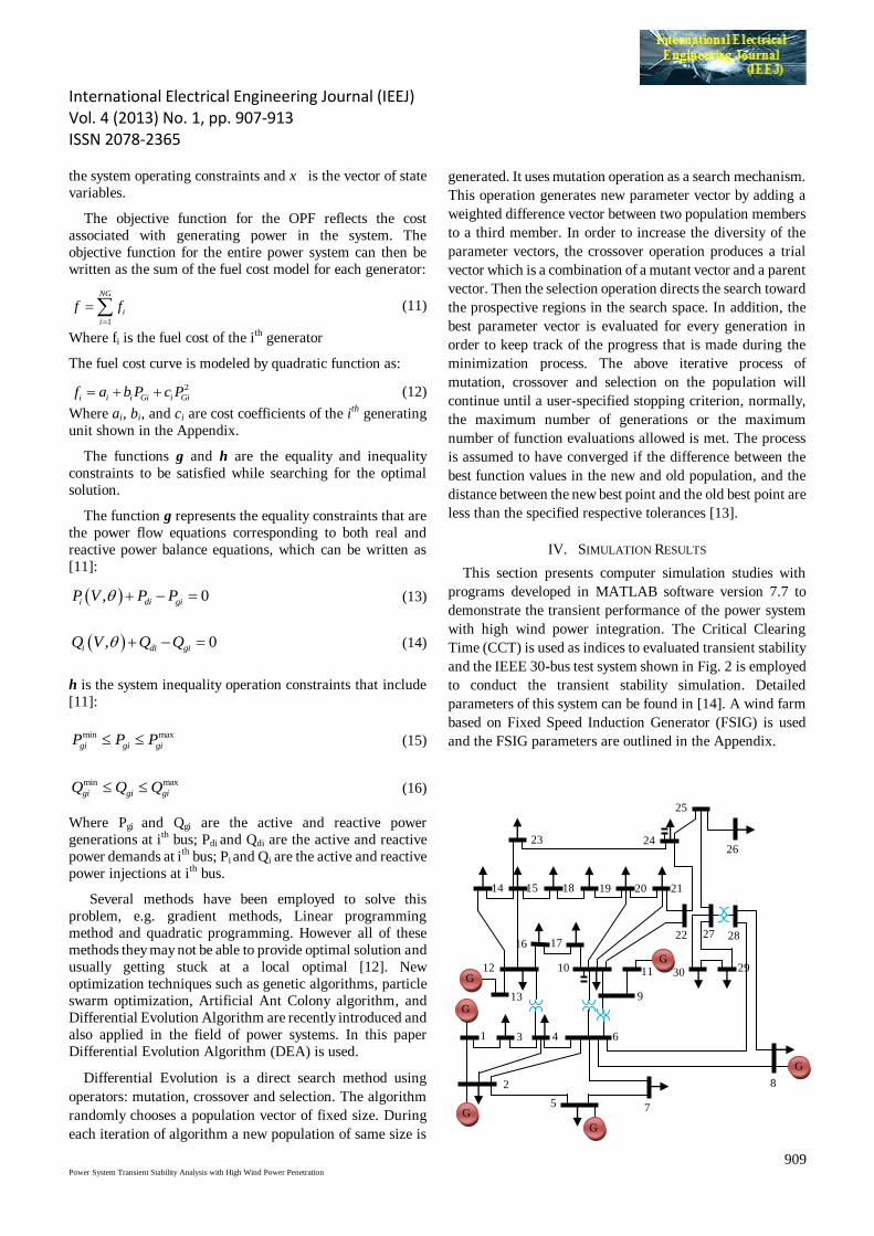
and the IEEE 30-bus test system shown in Fig. 2 is employed
to conduct the transient stability simulation. Detailed
parameters of this system can be found in [14]. A wind farm
based on Fixed Speed Induction Generator (FSIG) is used
and the FSIG parameters are outlined in the Appendix.
G
G
G
G
G
G
2
5
24 2
3
2
6
2
9 3
0
2
7
1 3
2
4
5
6
8
7
9
1
0
1
1 1
2
1
4 1
5
1
6
2
0
1
7
1
8
1
9
2
2
2
1
2
8
G
G
G
G
G
G
2
5 7
8
1 3 4 6
13 9
12 10 11 30 29
16 17
14 18 15 19 20 21
22 27 28
23 24 26
25
International Electrical Engineering Journal (IEEJ) Vol. 4 (2013) No. 1, pp. 907-913 ISSN 2078-2365
910 Power System Transient Stability Analysis with High Wind Power Penetration
Fig.3. Single line diagram of the IEEE 30-bus system
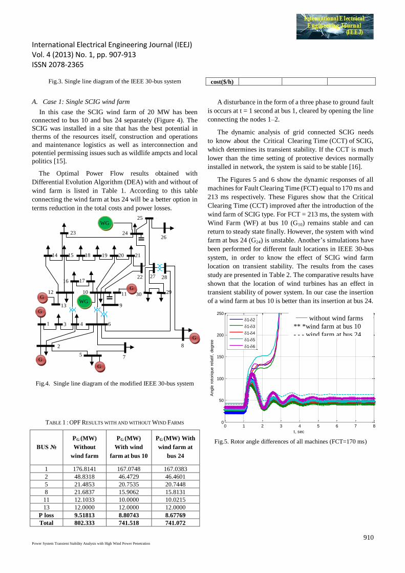
A. Case 1: Single SCIG wind farm
In this case the SCIG wind farm of 20 MW has been
connected to bus 10 and bus 24 separately (Figure 4). The
SCIG was installed in a site that has the best potential in
therms of the resources itself, construction and operations
and maintenance logistics as well as interconnection and
potentiel permissing issues such as wildlife ampcts and local
politics [15].
The Optimal Power Flow results obtained with
Differential Evolution Algorithm (DEA) with and without of
wind farm is listed in Table 1. According to this table
connecting the wind farm at bus 24 will be a better option in
terms reduction in the total costs and power losses.
Fig.4. Single line diagram of the modified IEEE 30-bus system
TABLE 1 : OPF RESULTS WITH AND WITHOUT WIND FARMS
BUS №
PG (MW)
Without
wind farm
PG (MW)
With wind
farm at bus 10
PG (MW) With
wind farm at
bus 24
1 176.8141 167.0748 167.0383
2 48.8318 46.4729 46.4601
5 21.4853 20.7535 20.7448
8 21.6837 15.9062 15.8131
11 12.1033 10.0000 10.0215
13 12.0000 12.0000 12.0000
P loss 9.51813 8.80743 8.67769
Total 802.333 741.518 741.072
cost($/h)
A disturbance in the form of a three phase to ground fault
is occurs at t = 1 second at bus 1, cleared by opening the line
connecting the nodes 1–2.
The dynamic analysis of grid connected SCIG needs
to know about the Critical Clearing Time (CCT) of SCIG,
which determines its transient stability. If the CCT is much
lower than the time setting of protective devices normally
installed in network, the system is said to be stable [16].
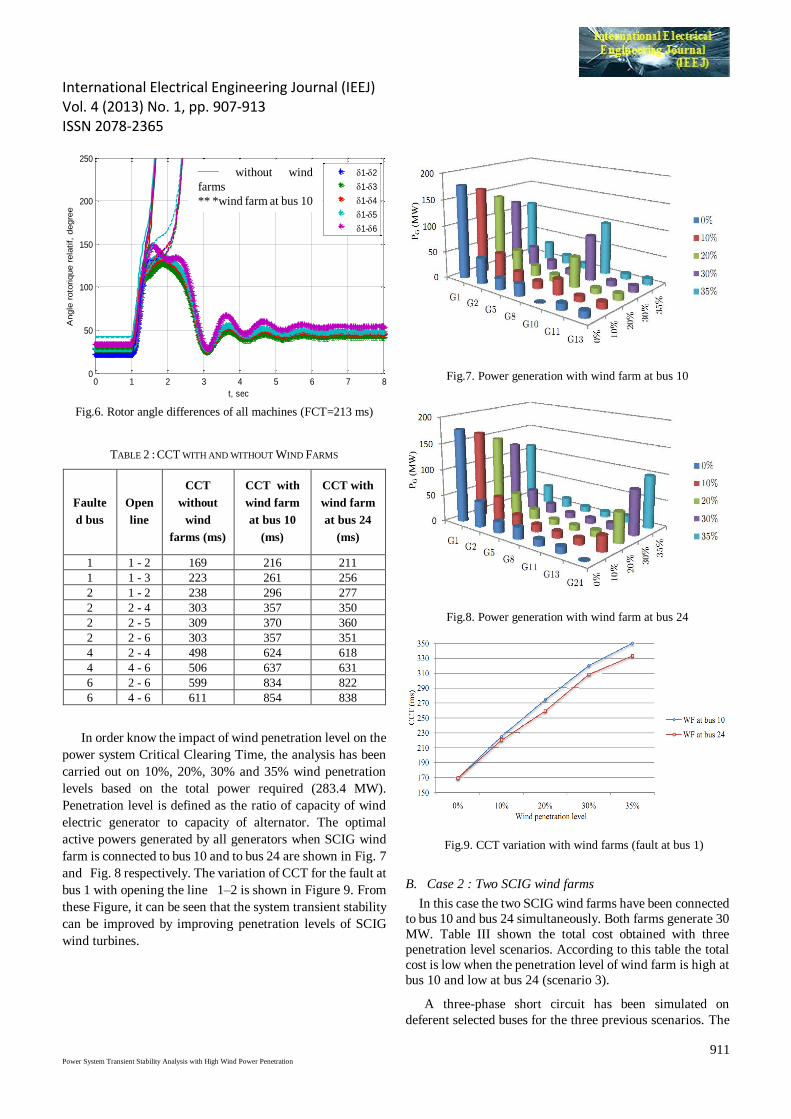
The Figures 5 and 6 show the dynamic responses of all
machines for Fault Clearing Time (FCT) equal to 170 ms and
213 ms respectively. These Figures show that the Critical
Clearing Time (CCT) improved after the introduction of the
wind farm of SCIG type. For FCT = 213 ms, the system with
Wind Farm (WF) at bus 10 (G10) remains stable and can
return to steady state finally. However, the system with wind
farm at bus 24 (G24) is unstable. Another’s simulations have
been performed for different fault locations in IEEE 30-bus
system, in order to know the effect of SCIG wind farm
location on transient stability. The results from the cases
study are presented in Table 2. The comparative results have
shown that the location of wind turbines has an effect in
transient stability of power system. In our case the insertion
of a wind farm at bus 10 is better than its insertion at bus 24.
0 1 2 3 4 5 6 7 80
50
100
150
200
250
t, sec
Angle
roto
rique r
ela
tif,
degre
e
1-2
1-3
1-4
1-5
1-6
**** éoliennes au jb 10
----- éoliennes au jb 24
___ sans éoliennes
Fig.5. Rotor angle differences of all machines (FCT=170 ms)
G
G
G
G
G
G
2
5
24 2
3
2
6
2
9 3
0
2
7
1 3
2
4
5
6
8
7
9
1
0
1
1
1
2
1
4 1
5
1
6
2
0
1
7
1
8
1
9
2
2
2
1
2
8
G
G
G
G
G
G
2
5 7
8
1 3 4 6
13 9
12 10 11 30 29
16 17
14 18 15 19 20 21
22 27 28
23 24 26
25
WG
WG
_____ without wind farms
** *wind farm at bus 10
- - - wind farm at bus 24
International Electrical Engineering Journal (IEEJ) Vol. 4 (2013) No. 1, pp. 907-913 ISSN 2078-2365
911 Power System Transient Stability Analysis with High Wind Power Penetration
0 1 2 3 4 5 6 7 80
50
100
150
200
250
t, sec
Angle
roto
rique r
ela
tif,
degre
e
1-2
1-3
1-4
1-5
1-6
**** éoliennes au jb 10
----- éoliennes au jb 24
___ sans éoliennes
Fig.6. Rotor angle differences of all machines (FCT=213 ms)
TABLE 2 : CCT WITH AND WITHOUT WIND FARMS
Faulte
d bus
Open
line
CCT
without
wind
farms (ms)
CCT with
wind farm
at bus 10
(ms)
CCT with
wind farm
at bus 24
(ms)
1 1 - 2 169 216 211
1 1 - 3 223 261 256
2 1 - 2 238 296 277
2 2 - 4 303 357 350
2 2 - 5 309 370 360
2 2 - 6 303 357 351
4 2 - 4 498 624 618
4 4 - 6 506 637 631
6 2 - 6 599 834 822
6 4 - 6 611 854 838
In order know the impact of wind penetration level on the
power system Critical Clearing Time, the analysis has been
carried out on 10%, 20%, 30% and 35% wind penetration
levels based on the total power required (283.4 MW).
Penetration level is defined as the ratio of capacity of wind
electric generator to capacity of alternator. The optimal
active powers generated by all generators when SCIG wind
farm is connected to bus 10 and to bus 24 are shown in Fig. 7
and Fig. 8 respectively. The variation of CCT for the fault at
bus 1 with opening the line 1–2 is shown in Figure 9. From
these Figure, it can be seen that the system transient stability
can be improved by improving penetration levels of SCIG
wind turbines.
Fig.7. Power generation with wind farm at bus 10
Fig.8. Power generation with wind farm at bus 24
Fig.9. CCT variation with wind farms (fault at bus 1)
B. Case 2 : Two SCIG wind farms
In this case the two SCIG wind farms have been connected
to bus 10 and bus 24 simultaneously. Both farms generate 30
MW. Table III shown the total cost obtained with three
penetration level scenarios. According to this table the total
cost is low when the penetration level of wind farm is high at
bus 10 and low at bus 24 (scenario 3).
A three-phase short circuit has been simulated on
deferent selected buses for the three previous scenarios. The
_____ without wind
farms
** *wind farm at bus 10
- - - wind farm at bus 24
International Electrical Engineering Journal (IEEJ) Vol. 4 (2013) No. 1, pp. 907-913 ISSN 2078-2365
912 Power System Transient Stability Analysis with High Wind Power Penetration
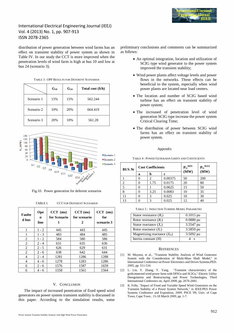
distribution of power generation between wind farms has an
effect on transient stability of power system as shown in
Table IV. In our study the CCT is more improved when the
penetration levels of wind farm is high at bus 10 and low at
bus 24 (scenario 3).
TABLE 3 : OPF RESULTS FOR DEFERENT SCENARIOS
G10 G24 Total cost ($/h)
Scenario 1 15% 15% 562.244
Scenario 2 10% 20% 664.419
Scenario 3 20% 10% 561.28
Fig.10. Power generation for deferent scenarios
TABLE I. CCT FOR DEFERENT SCENARIOS
Faulte
d bus
Ope
n
line
CCT (ms)
for Scenario
1
CCT (ms)
for scenario
2
CCT (ms)
for
scenario 3
1 1 - 2 445 443 445
1 1 - 3 483 484 485
2 1 - 2 584 580 586
2 2 - 4 631 635 636
2 2 - 5 626 629 631
2 2 - 6 638 642 644
4 2 - 4 1281 1286 1288
4 4 - 6 1278 1283 1286
6 2 - 6 1576 1587 1659
6 4 - 6 1558 1561 1564
V. CONCLUSION
The impact of increased penetration of fixed speed wind
generators on power system transient stability is discussed in
this paper. According to the simulation results, some
preliminary conclusions and comments can be summarized
as follows:
An optimal integration, location and utilization of
SCIG type wind generator to the power system
improved the transient stability;
Wind power plants affect voltage levels and power
flows in the networks. These effects can be
beneficial to the system, especially when wind
power plants are located near load centers.
The location and number of SCIG based wind
turbine has an effect on transient stability of
power system;
The increased of penetration level of wind
generation SCIG type increase the power system
Critical Clearing Time;
The distribution of power between SCIG wind
farms has an effect on transient stability of
power system.
Appendix
TABLE 4 : POWER GENERAION LIMITS AND COEFFICIENTS
BUS № Cost Coefficients PG
MIN
(MW)
PGMAX
(MW) a b c
1 0 2 0.00375 50 200
2 0 1.75 0.0175 20 80
5 0 1 0.0625 15 50
8 0 3.25 0.0083 10 35
11 0 3 0.025 10 30
13 0 3 0.025 12 40
TABLE 5 : INDUCTION TURBINE MODEL PARAMETRS
Stator resistance (Rs) 0.1015 pu
Rotor resistance (Rr) 0.0880 pu
Stator reactance (Xs) 3.5547 pu
Rotor reactance (Xr) 3.5859 pu
Magnetizing reactance (Xm) 3.5092 pu
Inertia constant (H) 4 s
REFERENCES
[1] M. Muyeen, et al., "Transient Stability Analysis of Wind Generator
System with the Consideration of Multi-Mass Shaft Model," in
International Conference on Power Electronics and Drives Systems,PED.
2005, pp. 511-516
[2] L. Lin, Y. Zhang, Y. Yang, "Transient characteristics of the
gridconnected wind power farm with DFIGs and SCIGs," Electric Utility
Deregulation and Restructuring and Power Technologies, Third
International Conference on, April 2008, pp. 2676-2681.
[3] K. Folly, "Impact of Fixed and Variable Speed Wind Generators on the
Transient Stability of a Power System Network," in IEEE/PES Power
Systems Conference and Exposition, 2009. PSCE '09, Univ. of Cape
Town, Cape Town , 15-18 March 2009, pp. 1-7.

International Electrical Engineering Journal (IEEJ) Vol. 4 (2013) No. 1, pp. 907-913 ISSN 2078-2365
913 Power System Transient Stability Analysis with High Wind Power Penetration
[4] S. Mohandas and A. Kumar, "Transient Stability Enhancement of the
Power System with Wind Generation," TELKOMNIKA, vol. 9, no. 2,
pp. 267-278, Aug. 2011.
[5] L. Shi, D. Ni, L. Yao, and M. Bazargan, "Transient stability of
power system with high penetration of DFIG based wind farms," in IEEE
Power & Energy Society General Meeting, 2009. PES '09. Univ.,
Shenzhen, China, 26-30 July 2009, pp. 1-6.
[6] S. Sheri, B. Shankarprasad, V. Bhat, and S. Jagadish, "Effect of
Doubly Fed Induction Gennerator on Transient Stability Analysis of
Grid" IEEE Transactions on Energy Conversion, vol. 20, no. 2, p.
388–397, June 2005.
[7] Reza Ebrahimpour, Easa Kazemi Abharian, Ali Akbar Motie Birjandi
and Seyed Zeinolabedin Moussavi, "Transient Stability Assessment of a
Power System with a UPFC by Mixture of Experts," nternational
Journal of Computer and Electrical Engineering, Vol. 2, No. 4, August,
2010, pp. 643-648.
[8] P. Kundur, Power System Stability and Control 1994 . New York:
Mc Graw-Hill, 1994.
[9] L. Holdsworth, "Comparison of fixed speed and doubly-fed induction
wind turbines during power system disturbances ," IEE
Proceedings-Generation, Transmission and Distribution, vol. 150, no.
3, pp. 343-352, 2003.
[10] Rodrigo Palma-Behnke, Luis S. Vargas, Juan R. Pérez, Jaime D. Núñez,
and Rigoberto A. Torres, "OPF With SVC and UPFC Modeling for
Longitudinal Systems", IEEE Transactions on Power Systems, Vol. 19,
No. 4, November 2004.
[11] T. Bouktir, L. Slimani, and M. Belkacem, "A Genetic Algorithm for
Solving the Optimal Power Flow Problem ," Leonardo Journal of
Sciences, no. 4, pp. 44-58, Jan. 2004.
[12] Aditya Tiwari, K. K. Swarnkar, S. Wadhwani & A. K. Wadhwani,
“Optimal Power Flow with Facts Devices using Genetic Algorithm,”
International Journal of Power System Operation and Energy
Management, ISSN (PRINT): 2231–4407, Volume-1, Issue-2, 2011.
[13] R. Storn, "Differential Evolution – A Simple and Efficient Heuristic for
Global Optimization over Continuous Spaces," Journal of Global
Optimization, p. 341–359, 1997.
[14] M. Iannone and F. Torelli, "Acoherency-basedmethod to
increasedynamicsecurity in power systems," Electric Power Systems
Research, vol. 78, no. 8, p. 1425–1436, Aug. 2008.
[15] L. Slimani, T. Bouktir,.Application of Differential Evolution Algorithm
to Optimal Power Flow Solution with High Wind Energy Penetration,
ACTA ELECTROTEHNIKA, ISSN: 1693-6930, Vol.53, No.1, 2012,
pp. 59-68.