power quality in renewable energy systems …12/keynote-jian-sun.pdfjian sun department of...
TRANSCRIPT
Power Quality in Renewable Energy Systems Challenges and Opportunities
Jian Sun
Department of Electrical, Computer, and Systems EngineeringRensselaer Polytechnic Institute
110 8th Street, Troy, NY 12180, USATelephone: (518) 276-8297; email: [email protected]
Abstract
Power quality in traditional power systems is concerned withvoltage problems caused by abnormal operation or nonlinear loadbehavior. The integration of renewable energy into the power gridintroduces new power quality problems. In addition to the inter-mittency of renewable production, which leads to more frequentvoltage fluctuation, and the switching in the power electronicsinterfaces, which injects high-frequency harmonics into thesystem, harmonic resonance and other dynamics power qualityproblems become more prevalent due to the complex and fastdynamics and control of power electronics interfaces. This paperreviews the sources of harmonic resonance involving renewableenergy and presents a systematic method to identify and charac-terize such dynamic power quality problems. A distributed gener-ation test-bed is also presented as an experimental platform forthe study of system harmonic resonance and other control-relatedpower quality and stability problems. Measurement resultsinvolving single-phase solar and three-phase wind inverters arepresented to validate the analysis method and to demonstratepossible mitigation techniques. The need for advanced auton-omous control that enhances system stability and mitigatessystem harmonic resonance are discussed. Issues related toelectromagnetic interference (EMI) generated by renewableenergy sources and the need to develop EMI compliance require-ments for such sources are also discussed.
Key Words
Harmonic Resonance, Impedance Analysis, DynamicPower Quality, Electromagnetic Interference
1. Introduction
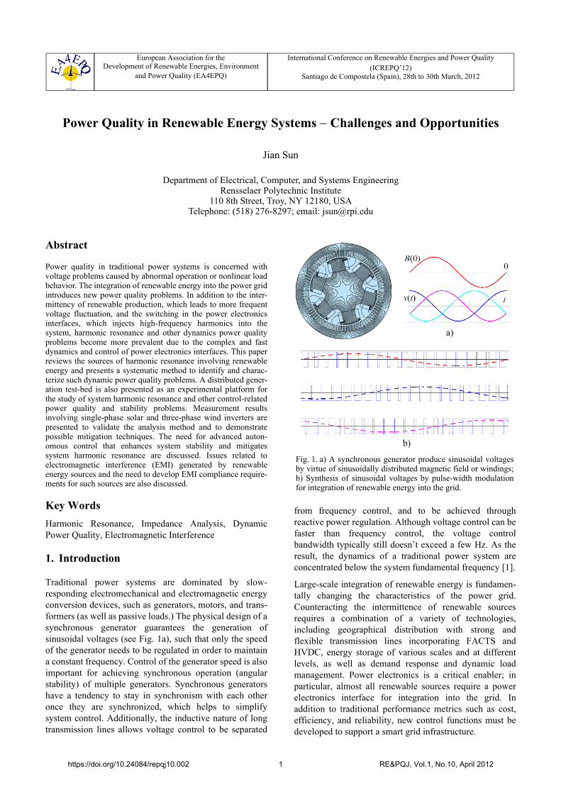
Traditional power systems are dominated by slow-responding electromechanical and electromagnetic energyconversion devices, such as generators, motors, and trans-formers (as well as passive loads.) The physical design of asynchronous generator guarantees the generation ofsinusoidal voltages (see Fig. 1a), such that only the speedof the generator needs to be regulated in order to maintaina constant frequency. Control of the generator speed is alsoimportant for achieving synchronous operation (angularstability) of multiple generators. Synchronous generatorshave a tendency to stay in synchronism with each otheronce they are synchronized, which helps to simplifysystem control. Additionally, the inductive nature of longtransmission lines allows voltage control to be separated
from frequency control, and to be achieved throughreactive power regulation. Although voltage control can befaster than frequency control, the voltage controlbandwidth typically still doesn’t exceed a few Hz. As theresult, the dynamics of a traditional power system areconcentrated below the system fundamental frequency [1].
Large-scale integration of renewable energy is fundamen-tally changing the characteristics of the power grid.Counteracting the intermittence of renewable sourcesrequires a combination of a variety of technologies,including geographical distribution with strong andflexible transmission lines incorporating FACTS andHVDC, energy storage of various scales and at differentlevels, as well as demand response and dynamic loadmanagement. Power electronics is a critical enabler; inparticular, almost all renewable sources require a powerelectronics interface for integration into the grid. Inaddition to traditional performance metrics such as cost,efficiency, and reliability, new control functions must bedeveloped to support a smart grid infrastructure.
European Association for theDevelopment of Renewable Energies, Environment
and Power Quality (EA4EPQ)
International Conference on Renewable Energies and Power Quality (ICREPQ’12)
Santiago de Compostela (Spain), 28th to 30th March, 2012
Fig. 1. a) A synchronous generator produce sinusoidal voltagesby virtue of sinusoidally distributed magnetic field or windings;b) Synthesis of sinusoidal voltages by pulse-width modulationfor integration of renewable energy into the grid.
a)
b)
https://doi.org/10.24084/repqj10.002 1 RE&PQJ, Vol.1, No.10, April 2012
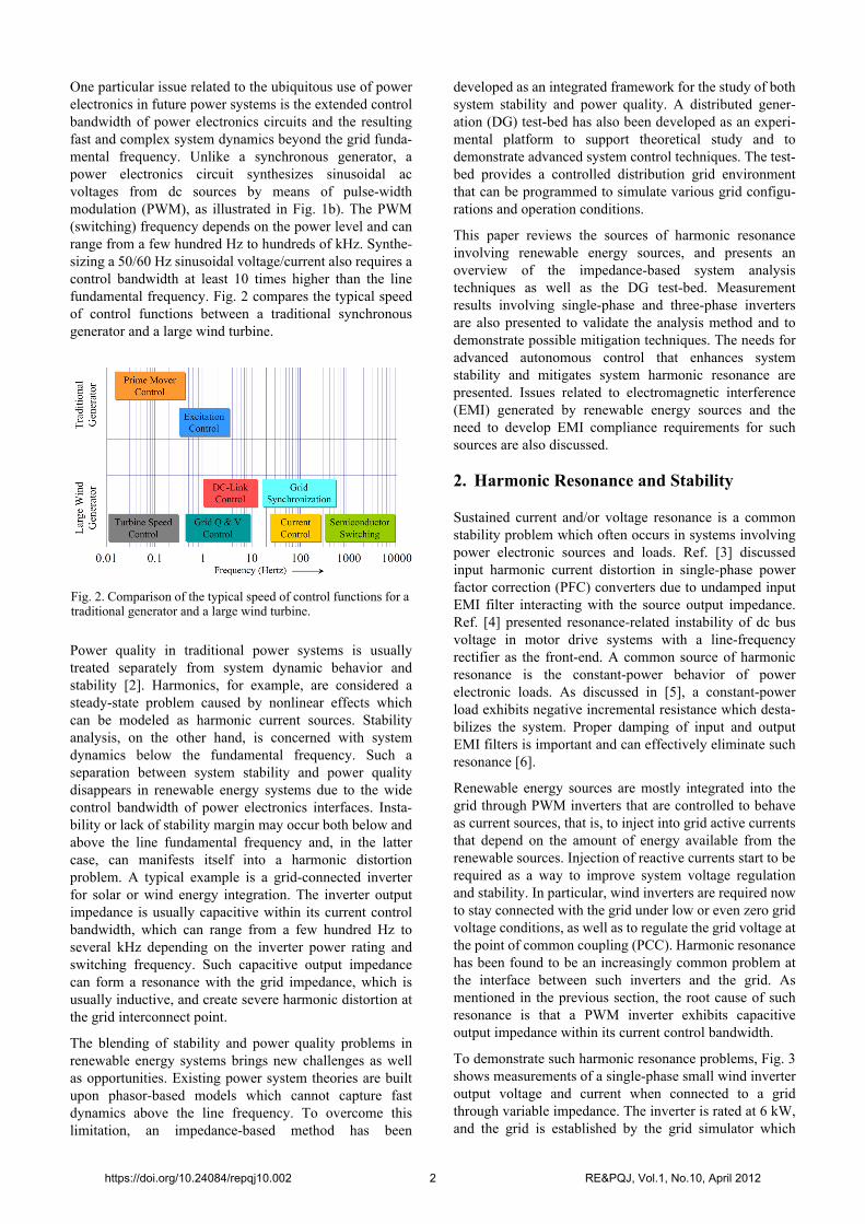
One particular issue related to the ubiquitous use of powerelectronics in future power systems is the extended controlbandwidth of power electronics circuits and the resultingfast and complex system dynamics beyond the grid funda-mental frequency. Unlike a synchronous generator, apower electronics circuit synthesizes sinusoidal acvoltages from dc sources by means of pulse-widthmodulation (PWM), as illustrated in Fig. 1b). The PWM(switching) frequency depends on the power level and canrange from a few hundred Hz to hundreds of kHz. Synthe-sizing a 50/60 Hz sinusoidal voltage/current also requires acontrol bandwidth at least 10 times higher than the linefundamental frequency. Fig. 2 compares the typical speedof control functions between a traditional synchronousgenerator and a large wind turbine.
Power quality in traditional power systems is usuallytreated separately from system dynamic behavior andstability [2]. Harmonics, for example, are considered asteady-state problem caused by nonlinear effects whichcan be modeled as harmonic current sources. Stabilityanalysis, on the other hand, is concerned with systemdynamics below the fundamental frequency. Such aseparation between system stability and power qualitydisappears in renewable energy systems due to the widecontrol bandwidth of power electronics interfaces. Insta-bility or lack of stability margin may occur both below andabove the line fundamental frequency and, in the lattercase, can manifests itself into a harmonic distortionproblem. A typical example is a grid-connected inverterfor solar or wind energy integration. The inverter outputimpedance is usually capacitive within its current controlbandwidth, which can range from a few hundred Hz toseveral kHz depending on the inverter power rating andswitching frequency. Such capacitive output impedancecan form a resonance with the grid impedance, which isusually inductive, and create severe harmonic distortion atthe grid interconnect point.
The blending of stability and power quality problems inrenewable energy systems brings new challenges as wellas opportunities. Existing power system theories are builtupon phasor-based models which cannot capture fastdynamics above the line frequency. To overcome thislimitation, an impedance-based method has been
developed as an integrated framework for the study of bothsystem stability and power quality. A distributed gener-ation (DG) test-bed has also been developed as an experi-mental platform to support theoretical study and todemonstrate advanced system control techniques. The test-bed provides a controlled distribution grid environmentthat can be programmed to simulate various grid configu-rations and operation conditions.
This paper reviews the sources of harmonic resonanceinvolving renewable energy sources, and presents anoverview of the impedance-based system analysistechniques as well as the DG test-bed. Measurementresults involving single-phase and three-phase invertersare also presented to validate the analysis method and todemonstrate possible mitigation techniques. The needs foradvanced autonomous control that enhances systemstability and mitigates system harmonic resonance arepresented. Issues related to electromagnetic interference(EMI) generated by renewable energy sources and theneed to develop EMI compliance requirements for suchsources are also discussed.
2. Harmonic Resonance and Stability
Sustained current and/or voltage resonance is a commonstability problem which often occurs in systems involvingpower electronic sources and loads. Ref. [3] discussedinput harmonic current distortion in single-phase powerfactor correction (PFC) converters due to undamped inputEMI filter interacting with the source output impedance.Ref. [4] presented resonance-related instability of dc busvoltage in motor drive systems with a line-frequencyrectifier as the front-end. A common source of harmonicresonance is the constant-power behavior of powerelectronic loads. As discussed in [5], a constant-powerload exhibits negative incremental resistance which desta-bilizes the system. Proper damping of input and outputEMI filters is important and can effectively eliminate suchresonance [6].
Renewable energy sources are mostly integrated into thegrid through PWM inverters that are controlled to behaveas current sources, that is, to inject into grid active currentsthat depend on the amount of energy available from therenewable sources. Injection of reactive currents start to berequired as a way to improve system voltage regulationand stability. In particular, wind inverters are required nowto stay connected with the grid under low or even zero gridvoltage conditions, as well as to regulate the grid voltage atthe point of common coupling (PCC). Harmonic resonancehas been found to be an increasingly common problem atthe interface between such inverters and the grid. Asmentioned in the previous section, the root cause of suchresonance is that a PWM inverter exhibits capacitiveoutput impedance within its current control bandwidth.
To demonstrate such harmonic resonance problems, Fig. 3shows measurements of a single-phase small wind inverteroutput voltage and current when connected to a gridthrough variable impedance. The inverter is rated at 6 kW,and the grid is established by the grid simulator which
Fig. 2. Comparison of the typical speed of control functions for atraditional generator and a large wind turbine.
https://doi.org/10.24084/repqj10.002 2 RE&PQJ, Vol.1, No.10, April 2012
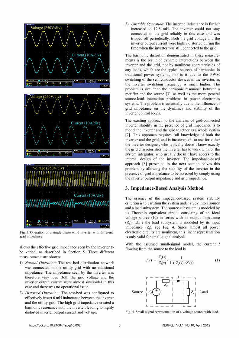
allows the effective grid impedance seen by the inverter tobe varied, as described in Section 5. Three differentmeasurements are shown:
1) Normal Operation: The test-bed distribution networkwas connected to the utility grid with no additionalimpedance. The impedance seen by the inverter wastherefore very low. Both the grid voltage and theinverter output current were almost sinusoidal in thiscase and there was no operational issue.
2) Distorted Operation: The test-bed was configured toeffectively insert 6 mH inductance between the inverterand the utility grid. The high grid impedance created aharmonic resonance with the inverter, leading to highlydistorted inverter output current and voltage.
3) Unstable Operation: The inserted inductance is furtherincreased to 12.5 mH. The inverter could not stayconnected to the grid reliably in this case and wastripped off periodically. Both the grid voltage and theinverter output current were highly distorted during thetime when the inverter was still connected to the grid.
The harmonic distortion demonstrated in these measure-ments is the result of dynamic interactions between theinverter and the grid, not by nonlinear characteristics ofany loads, which are the typical sources of harmonics intraditional power systems, nor is it due to the PWMswitching of the semiconductor devices in the inverter, asthe inverter switching frequency is much higher. Theproblem is similar to the harmonic resonance between arectifier and the source [3], as well as the more generalsource-load interaction problems in power electronicssystems. The problem is essentially due to the influence ofgrid impedance on the dynamics and stability of theinverter control loops.
The existing approach to the analysis of grid-connectedinverter stability in the presence of grid impedance is tomodel the inverter and the grid together as a whole system[7]. This approach requires full knowledge of both theinverter and the grid, and is inconvenient to use for eitherthe inverter designer, who typically doesn’t know exactlythe grid characteristics the inverter has to work with, or thesystem integrator, who usually doesn’t have access to theinternal design of the inverter. The impedance-basedapproach [8] presented in the next section solves thisproblem by allowing the stability of the inverter in thepresence of grid impedance to be assessed by simply usingthe inverter output impedance and grid impedance.
3. Impedance-Based Analysis Method
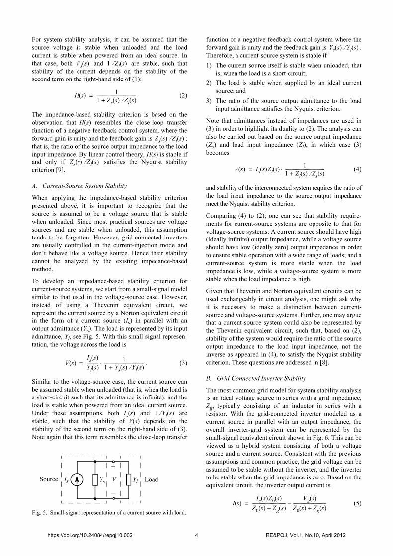
The essence of the impedance-based system stabilitycriterion is to partition the system under study into a sourceand a load subsystem. The source subsystem is modeled byits Thevenin equivalent circuit consisting of an idealvoltage source (Vs) in series with an output impedance(Zs), while the load subsystem is modeled by its inputimpedance (Zl), see Fig. 4. Since almost all powerelectronic circuits are nonlinear, this linear representationis only valid for small-signal analysis.
With the assumed small-signal model, the current Iflowing from the source to the load is
(1)
Fig. 3. Operation of a single-phase wind inverter with differentgrid impedance.
Voltage (250V/div)
Current (10A/div)
Voltage (250V/div)
Current (10A/div)
Voltage (250V/div)
Current (10A/div)
+
Zs
ZlVs
I
Fig. 4. Small-signal representation of a voltage source with load.
Source Load
I s( )Vs s( )
Zl s( )----------- 1
1 Zs s( ) Zl s( )+------------------------------------=
https://doi.org/10.24084/repqj10.002 3 RE&PQJ, Vol.1, No.10, April 2012
For system stability analysis, it can be assumed that thesource voltage is stable when unloaded and the loadcurrent is stable when powered from an ideal source. Inthat case, both and are stable, such thatstability of the current depends on the stability of thesecond term on the right-hand side of (1):
(2)
The impedance-based stability criterion is based on theobservation that H(s) resembles the close-loop transferfunction of a negative feedback control system, where theforward gain is unity and the feedback gain is ;that is, the ratio of the source output impedance to the loadinput impedance. By linear control theory, H(s) is stable ifand only if satisfies the Nyquist stabilitycriterion [9].
A. Current-Source System Stability
When applying the impedance-based stability criterionpresented above, it is important to recognize that thesource is assumed to be a voltage source that is stablewhen unloaded. Since most practical sources are voltagesources and are stable when unloaded, this assumptiontends to be forgotten. However, grid-connected invertersare usually controlled in the current-injection mode anddon’t behave like a voltage source. Hence their stabilitycannot be analyzed by the existing impedance-basedmethod.
To develop an impedance-based stability criterion forcurrent-source systems, we start from a small-signal modelsimilar to that used in the voltage-source case. However,instead of using a Thevenin equivalent circuit, werepresent the current source by a Norton equivalent circuitin the form of a current source (Is) in parallel with anoutput admittance (Ys). The load is represented by its inputadmittance, Yl, see Fig. 5. With this small-signal represen-tation, the voltage across the load is
. (3)
Similar to the voltage-source case, the current source canbe assumed stable when unloaded (that is, when the load isa short-circuit such that its admittance is infinite), and theload is stable when powered from an ideal current source.Under these assumptions, both and arestable, such that the stability of V(s) depends on thestability of the second term on the right-hand side of (3).Note again that this term resembles the close-loop transfer
function of a negative feedback control system where theforward gain is unity and the feedback gain is .Therefore, a current-source system is stable if
1) The current source itself is stable when unloaded, thatis, when the load is a short-circuit;
2) The load is stable when supplied by an ideal currentsource; and
3) The ratio of the source output admittance to the loadinput admittance satisfies the Nyquist criterion.
Note that admittances instead of impedances are used in(3) in order to highlight its duality to (2). The analysis canalso be carried out based on the source output impedance(Zs) and load input impedance (Zl), in which case (3)becomes
(4)
and stability of the interconnected system requires the ratio ofthe load input impedance to the source output impedancemeet the Nyquist stability criterion.
Comparing (4) to (2), one can see that stability require-ments for current-source systems are opposite to that forvoltage-source systems: A current source should have high(ideally infinite) output impedance, while a voltage sourceshould have low (ideally zero) output impedance in orderto ensure stable operation with a wide range of loads; and acurrent-source system is more stable when the loadimpedance is low, while a voltage-source system is morestable when the load impedance is high.
Given that Thevenin and Norton equivalent circuits can beused exchangeably in circuit analysis, one might ask whyit is necessary to make a distinction between current-source and voltage-source systems. Further, one may arguethat a current-source system could also be represented bythe Thevenin equivalent circuit, such that, based on (2),stability of the system would require the ratio of the sourceoutput impedance to the load input impedance, not theinverse as appeared in (4), to satisfy the Nyquist stabilitycriterion. These questions are addressed in [8].
B. Grid-Connected Inverter Stability
The most common grid model for system stability analysisis an ideal voltage source in series with a grid impedance,Zg, typically consisting of an inductor in series with aresistor. With the grid-connected inverter modeled as acurrent source in parallel with an output impedance, theoverall inverter-grid system can be represented by thesmall-signal equivalent circuit shown in Fig. 6. This can beviewed as a hybrid system consisting of both a voltagesource and a current source. Consistent with the previousassumptions and common practice, the grid voltage can beassumed to be stable without the inverter, and the inverterto be stable when the grid impedance is zero. Based on theequivalent circuit, the inverter output current is
(5)
Vs s( ) 1 Zl s( )
H s( ) 11 Zs s( ) Zl s( )+------------------------------------=
Zs s( ) Zl s( )
Zs s( ) Zl s( )
Ys YlIs V
Fig. 5. Small-signal representation of a current source with load.
LoadSource
+
V s( )Is s( )
Yl s( )----------- 1
1 Ys s( ) Yl s( )+------------------------------------=
Is s( ) 1 Yl s( )
Ys s( ) Yl s( )
V s( ) Is s( )Zl s( )1
1 Zl s( ) Zs s( )+------------------------------------=
I s( )Ic s( )Z0 s( )
Z0 s( ) Zg s( )+------------------------------
Vg s( )
Z0 s( ) Zg s( )+------------------------------–=
https://doi.org/10.24084/repqj10.002 4 RE&PQJ, Vol.1, No.10, April 2012

which can be rearranged to
. (6)
Based on (6) and the assumptions stated before, a grid-connected inverter will operate stably if the ratio of thegrid impedance to the inverter output impedance,
, satisfies the Nyquist criterion. Stabilitymargin of the system can also be measured from theNyquist plot of . Note that one arrives at thesame conclusion if the system is treated as a voltage-source system powered by the grid.
4. Impedance Modeling
Proper impedance models are required for the applicationof the impedance-based system stability criterionpresented in the previous section. The grid can usually bemodeled by an inductor or an inductor in series with aresistor. Such simple RL model, however, will no longerbe valid in the future when a significant portion of systempower is supplied from renewable sources throughinverters. More specifically, the grid impedance would bedominated more by inverters that integrate renewablesources than traditional generators and transmission/distri-bution networks. Since all inverters are nonlinear, small-signal analysis is necessary in order to develop their outputimpedance models for system stability analysis.
A fundamental difficulty in developing small-signalimpedance models for grid-connected inverters and otherpower electronics devices is that the system operates alonga sinusoidal trajectory and lacks a constant operation pointabout which the system model can be linearized byconventional small-signal analysis methods. Traditionalpower system theories overcome this difficulty by repre-senting the system by voltage and current phasors [1].Since both the amplitude and phase of a phasor areconstant when the system is in steady-state, the nonlinearphasor model can be linearized by conventional small-signal methods to develop a linear system model forstability analysis and control design. However, suchphasor-based models are only valid below the line funda-mental frequency and, hence, cannot be used for theanalysis of harmonic resonance and other high-frequencyphenomena. Additionally, a phasor model cannot be usedto determine the input and output impedance of a converter[9], hence is not compatible with the impedance-basedsystem analysis approach.
A balanced three-phase system can be transformed into arotating dq reference frame, in which balanced three-phase
sinusoidal voltages and currents become dc quantitieswhen the rotating speed of the reference frame is synchro-nized to the fundamental frequency. This technique iswidely used in motor drive control design and has beenapplied to study the stability of three-phase PWMconverters. One limitation of this method is that the trans-formed model is coupled in the dq-coordinate system, suchthat the generalized Nyquist criterion has to be applied[10], which is more complex. The method also suffersfrom several other limitations [9]:
1) The method cannot be applied to single-phase systems,or three-phase systems with significant single-phaseloads. A unbalanced three-phase system can be trans-formed, but the 0-axis variables will be non-zero andchange periodically with time, making it impossible tolinearize the model.
2) In many cases, there is no clear physical interpretationfor the impedances in the d- and q-axis as well as thecoupling between them. Experimental measurement ofsuch impedances is also difficult because of therequirement for special equipment and instruments.
3) The model in the dq coordinate system remains time-varying if any of the three-phase variables containsmore than one sinusoidal component. Hence themethod cannot be applied to study the effects ofharmonics on system stability.
To overcome the limitations of the phasor and the dq-transformation method, we have developed a new small-signal analysis method called harmonic linearization.Harmonic linearization is a technique that develops asmall-signal linear model for a nonlinear system along aperiodic, time-varying operation trajectory. The operationtrajectory may comprise a single or multiple sinusoidal(harmonic) components. The method is conceptuallysimple, involving superimposing harmonic perturbation tothe excitation of the system, determining the resultingresponses of variables of interests, and extracting thecorresponding components at the perturbation frequencyby invoking the harmonic balance principle and small-signal approximation, that is, by assuming that theharmonic perturbation is sufficiently small. The methodwas first developed to model the input impedance of line-commutated converters [11, 12], and was recentlyextended to model PWM inverters and converters for high-voltage dc (HVDC) applications [13-15].
In addition to its general applicability, the harmonic linear-ization method has several other advantages, particularlycompared to modeling in the dq-coordinate system:
1) The method effectively decomposes a three-phasesystem into a positive-sequence and a negative-sequence subsystem† without cross coupling betweenthem. Since the sequence transformation is linear andtime-invariant, a system is stable if and only if it isstable in all sequence domains.
2) The steady-state operation trajectory can include anynumber of harmonics, as demonstrated in [12] for a
I s( ) Ic s( )Vg s( )
Z0 s( )------------–
11 Zg s( ) Z0 s( )+-------------------------------------=
Zg s( ) Z0 s( )
Zg s( ) Z0 s( )
Z0
Zg
Ic
I
Fig. 6. Small-signal representation of an inverter-grid system.
GridInverter +_Vg
†. As well as a zero-sequence subsystem if unbalance conditions exist anda zero-sequence current can flow.
https://doi.org/10.24084/repqj10.002 5 RE&PQJ, Vol.1, No.10, April 2012
single-phase diode rectifier.
3) The method can handle both balanced and unbalancedsystems, including single-phase systems.
4) The resulting impedance models can be valid bothabove and below the ac fundamental frequency,depending only on the characteristics of the converter.
5) The calculated impedance has clear physical interpreta-tions and can be directly measured.
As an example, a PWM inverter employing direct phasecurrent control can be modeled by the following imped-ances, where Hi(s) is the transfer function of the phasecurrent compensator, L is the output inductance, Vdc is thedc bus voltage, TPLL is the loop gain of the phase-lockedloop (PLL) that is used to synchronize with the grid, and I1and are the amplitude and phase angle of the outputcurrent, respectively:
1) Positive-Sequence Output Impedance:
(7)
2) Negative-Sequence Output Impedance:
(8)
5. Distributed Generation Test-Bed
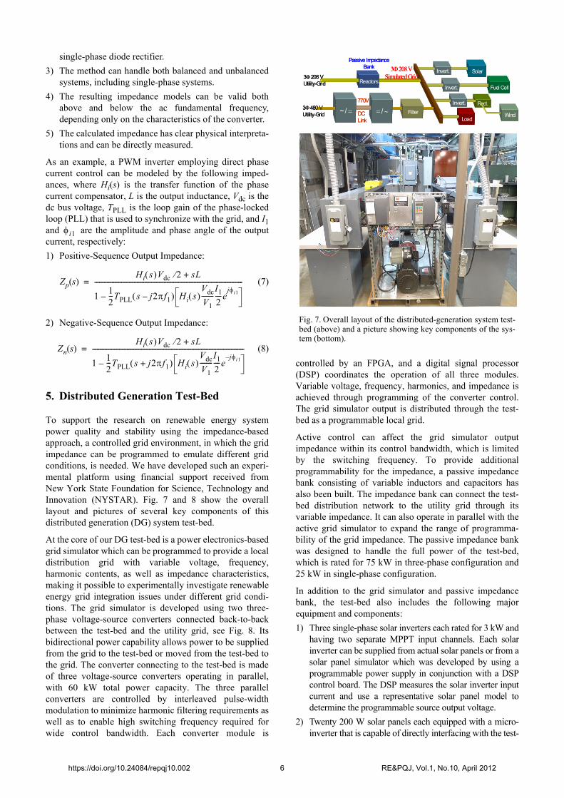
To support the research on renewable energy systempower quality and stability using the impedance-basedapproach, a controlled grid environment, in which the gridimpedance can be programmed to emulate different gridconditions, is needed. We have developed such an experi-mental platform using financial support received fromNew York State Foundation for Science, Technology andInnovation (NYSTAR). Fig. 7 and 8 show the overalllayout and pictures of several key components of thisdistributed generation (DG) system test-bed.
At the core of our DG test-bed is a power electronics-basedgrid simulator which can be programmed to provide a localdistribution grid with variable voltage, frequency,harmonic contents, as well as impedance characteristics,making it possible to experimentally investigate renewableenergy grid integration issues under different grid condi-tions. The grid simulator is developed using two three-phase voltage-source converters connected back-to-backbetween the test-bed and the utility grid, see Fig. 8. Itsbidirectional power capability allows power to be suppliedfrom the grid to the test-bed or moved from the test-bed tothe grid. The converter connecting to the test-bed is madeof three voltage-source converters operating in parallel,with 60 kW total power capacity. The three parallelconverters are controlled by interleaved pulse-widthmodulation to minimize harmonic filtering requirements aswell as to enable high switching frequency required forwide control bandwidth. Each converter module is
controlled by an FPGA, and a digital signal processor(DSP) coordinates the operation of all three modules.Variable voltage, frequency, harmonics, and impedance isachieved through programming of the converter control.The grid simulator output is distributed through the test-bed as a programmable local grid.
Active control can affect the grid simulator outputimpedance within its control bandwidth, which is limitedby the switching frequency. To provide additionalprogrammability for the impedance, a passive impedancebank consisting of variable inductors and capacitors hasalso been built. The impedance bank can connect the test-bed distribution network to the utility grid through itsvariable impedance. It can also operate in parallel with theactive grid simulator to expand the range of programma-bility of the grid impedance. The passive impedance bankwas designed to handle the full power of the test-bed,which is rated for 75 kW in three-phase configuration and25 kW in single-phase configuration.
In addition to the grid simulator and passive impedancebank, the test-bed also includes the following majorequipment and components:
1) Three single-phase solar inverters each rated for 3 kW andhaving two separate MPPT input channels. Each solarinverter can be supplied from actual solar panels or from asolar panel simulator which was developed by using aprogrammable power supply in conjunction with a DSPcontrol board. The DSP measures the solar inverter inputcurrent and use a representative solar panel model todetermine the programmable source output voltage.
2) Twenty 200 W solar panels each equipped with a micro-inverter that is capable of directly interfacing with the test-
i1
Zp s( )Hi s Vdc 2 sL+
112---TPLL s j2f1– Hi s
Vdc
V1--------
I1
2----e
ji1–
----------------------------------------------------------------------------------------------=
Zn s( )Hi s Vdc 2 sL+
112---TPLL s j2f1+ Hi s
Vdc
V1--------
I1
2----e
ji1––
------------------------------------------------------------------------------------------------=
Fig. 7. Overall layout of the distributed-generation system test-bed (above) and a picture showing key components of the sys-tem (bottom).
Solar
Load
Rect.
Fuel Cell
Wind
Invert.
Invert.
Invert.Reactors
Filter / ~ / DCLink
3208 VSimulated Grid
3480 VUtility-Grid
3208 VUtility-Grid
Passive ImpedanceBank
770V
Solar
Load
Rect.
Fuel Cell
Wind
Invert.
Invert.
Invert.Reactors
Filter / ~ / DCLink
3208 VSimulated Grid
3480 VUtility-Grid
3208 VUtility-Grid
Passive ImpedanceBank
770V
https://doi.org/10.24084/repqj10.002 6 RE&PQJ, Vol.1, No.10, April 2012
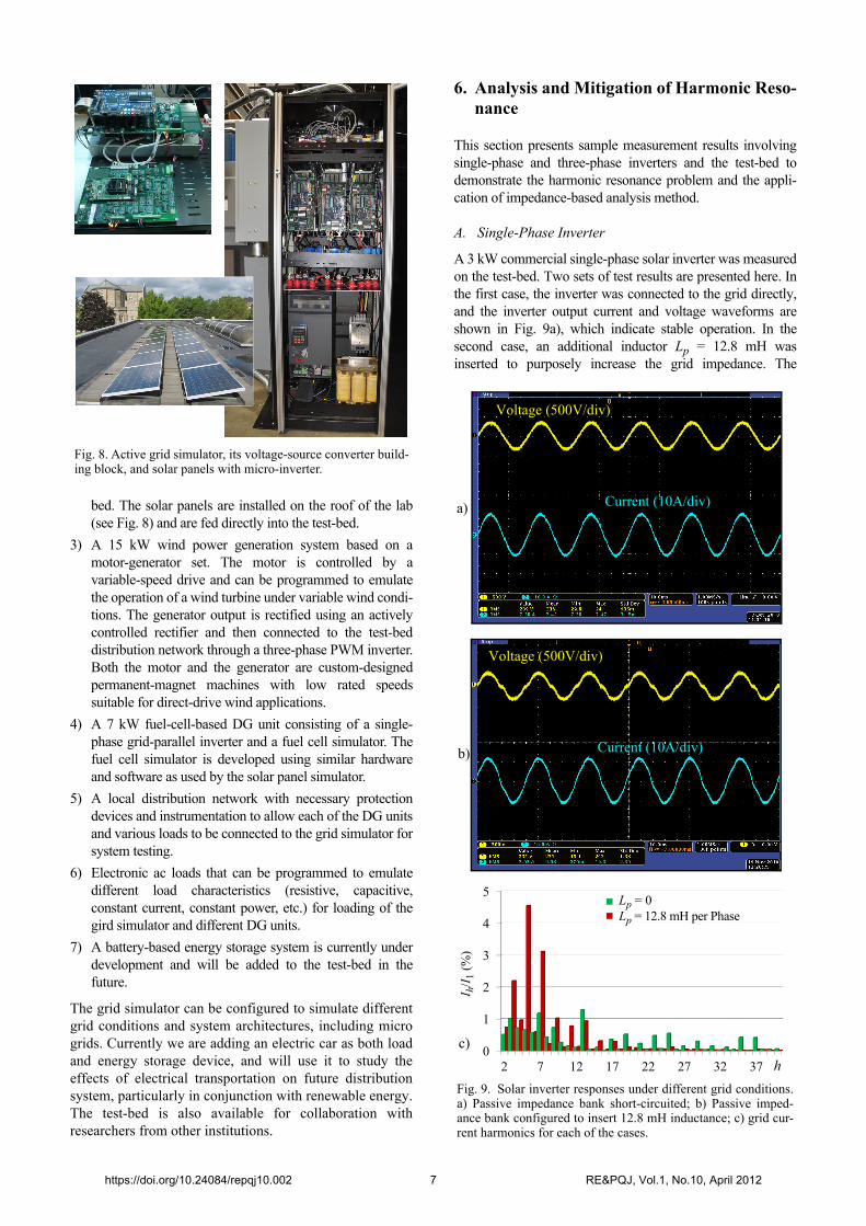
bed. The solar panels are installed on the roof of the lab(see Fig. 8) and are fed directly into the test-bed.
3) A 15 kW wind power generation system based on amotor-generator set. The motor is controlled by avariable-speed drive and can be programmed to emulatethe operation of a wind turbine under variable wind condi-tions. The generator output is rectified using an activelycontrolled rectifier and then connected to the test-beddistribution network through a three-phase PWM inverter.Both the motor and the generator are custom-designedpermanent-magnet machines with low rated speedssuitable for direct-drive wind applications.
4) A 7 kW fuel-cell-based DG unit consisting of a single-phase grid-parallel inverter and a fuel cell simulator. Thefuel cell simulator is developed using similar hardwareand software as used by the solar panel simulator.
5) A local distribution network with necessary protectiondevices and instrumentation to allow each of the DG unitsand various loads to be connected to the grid simulator forsystem testing.
6) Electronic ac loads that can be programmed to emulatedifferent load characteristics (resistive, capacitive,constant current, constant power, etc.) for loading of thegird simulator and different DG units.
7) A battery-based energy storage system is currently underdevelopment and will be added to the test-bed in thefuture.
The grid simulator can be configured to simulate differentgrid conditions and system architectures, including microgrids. Currently we are adding an electric car as both loadand energy storage device, and will use it to study theeffects of electrical transportation on future distributionsystem, particularly in conjunction with renewable energy.The test-bed is also available for collaboration withresearchers from other institutions.
6. Analysis and Mitigation of Harmonic Reso-nance
This section presents sample measurement results involvingsingle-phase and three-phase inverters and the test-bed todemonstrate the harmonic resonance problem and the appli-cation of impedance-based analysis method.
A. Single-Phase Inverter
A 3 kW commercial single-phase solar inverter was measuredon the test-bed. Two sets of test results are presented here. Inthe first case, the inverter was connected to the grid directly,and the inverter output current and voltage waveforms areshown in Fig. 9a), which indicate stable operation. In thesecond case, an additional inductor Lp = 12.8 mH wasinserted to purposely increase the grid impedance. The
Fig. 8. Active grid simulator, its voltage-source converter build-ing block, and solar panels with micro-inverter.
Fig. 9. Solar inverter responses under different grid conditions.a) Passive impedance bank short-circuited; b) Passive imped-ance bank configured to insert 12.8 mH inductance; c) grid cur-rent harmonics for each of the cases.
Voltage (500V/div)
Current (10A/div)a)
b)
Voltage (500V/div)
Current (10A/div)
0
1
2
3
4
5
2 7 12 17 22 27 32 37
Lp = 0Lp = 12.8 mH per Phase
I h/I
1 (%
)
h
c)
https://doi.org/10.24084/repqj10.002 7 RE&PQJ, Vol.1, No.10, April 2012

measured inverter output current and voltage waveforms arepresented in Fig. 9b). The grid current spectrum, shown inFig. 9c), indicates significant 5th and 7th harmonics. Theinverter output power was 1700 W in both cases.
To apply the impedance-based stability criterion presented inthe previous section, the output impedance of the inverter andthe grid impedance was measured by using a frequencyanalyzer for each test condition. Fig. 10 shows the measuredfrequency responses of the inverter output impedance and thegrid impedance for the two cases tested. Without theadditional inductor Lp, the grid impedance intersects with theinverter output impedance at three different frequencies (3kHz, 8 kHz, and 25 kHz) where the phase difference is 115o,20o, and 110o, respectively, indicating sufficient phasemargin in system stability at all points. With the additional12.8 mH inductor, the grid impedance intersects with theinverter output impedance only once at about 420 Hz, wherethe phase difference is about 160o. This intersectionfrequency correlates closely with the dominant harmonicfrequencies in the measured inverter output current andvoltage, indicating that the harmonics are caused by amarginally stable resonance between the inverter and the gridimpedance at this frequency.
B. Three-Phase Inverter
A three-phase PMW inverter was implemented using thesame voltage-source converter that was used to build theactive grid simulator in the test-bed. The inverter uses a PLLto synchronize with the grid, and a PI regulator to control thephase current. An additional high-frequency pole was used inthe current compensator to reduce high-frequency ripple inthe current. The output impedances of the inverter aredescribed by (7) and (8) given in Section 4.
The control was implemented in a digital signal processorTMS320F28335. The digital control introduces a delay inthe current control loop, which affects the outputimpedance. Given the sampling time, Ts, and computationdelay, Td, the effects can be included by adding a transferfunction
(9)
to the PWM output. In experiments, the total time delay wasmeasured to be 78 s. The frequency responses of the inverteroutput impedance are predicted using the impedance modelsand are compared in Fig. 11 with the actual measurements ofthe inverter output impedance.
The inverter was measured in the test-bed by configuringthe passive grid simulator to effectively provide 4.9 mH gridimpedance. To demonstrate the effects of inverter control onthe stability of the inverter-grid system, we tested the inverterwith two different bandwidths of the PLL. In the first case, thePLL bandwidth was set at 100 Hz, and the correspondingcurrent responses of the inverter are shown in Fig. 12a). Largedistortion due to harmonic resonance between the inverter andthe grid can be seen. Fig. 12c) shows the spectrum of theinverter output current and the Nyquist plot of the ratio of thegrid impedance to the inverter output impedance. The positiveimpedance ratio shows that the system is stable but with onlyless than 20o phase margin. The small phase margin leadsunder-damped resonance and explains the observed strong 3rd
and 4th harmonics.
Fig. 12b) shows the measured current waveforms when thePLL bandwidth is reduced to 10 Hz PLL. The corre-sponding current spectrum and Nyquist plots of the
Mag
nitu
de (
dB
)P
hase
(D
EG
)
100 Hz 1 kHz 10 kHz 100 kH
100 Hz 1 kHz 10 kHz 100 kHz
60
40
20
0
150
50
-50
-150
Fig. 10. Frequency responses of the single-phase solar inverteroutput and the grid impedance.
Zg(s) with Lp
Z0(s)
Z0(s)
Zg(s) without Lp
Zg(s) with Lp Zg(s) without Lp
esTd– 1 e
sTs––sTs
--------------------
10 Hz 102 Hz 103 Hz 104 Hz
20
30
40
50
60
10 Hz 102 Hz 103 Hz 104 Hz
-150
-100
-50
0
50
100
150
Fig. 11. Positive- and negative-sequence output impedanceresponses of a three-phase inverter. Solid lines: model predic-tion; Dash-dot: experimental measurements.
Mag
nitu
de (
dB
)P
hase
(de
gree
)
Zp
Zn
Zp
Zn
https://doi.org/10.24084/repqj10.002 8 RE&PQJ, Vol.1, No.10, April 2012
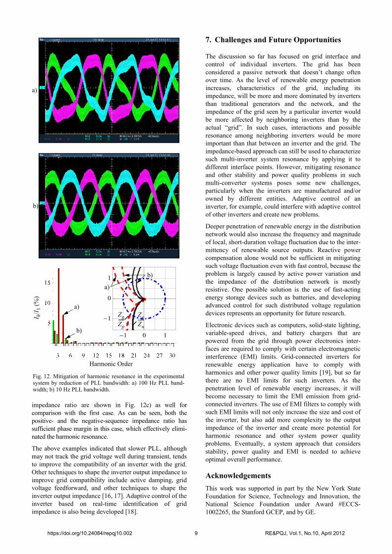
impedance ratio are shown in Fig. 12c) as well forcomparison with the first case. As can be seen, both thepositive- and the negative-sequence impedance ratio hassufficient phase margin in this case, which effectively elimi-nated the harmonic resonance.
The above examples indicated that slower PLL, althoughmay not track the grid voltage well during transient, tendsto improve the compatibility of an inverter with the grid.Other techniques to shape the inverter output impedance toimprove grid compatibility include active damping, gridvoltage feedforward, and other techniques to shape theinverter output impedance [16, 17]. Adaptive control of theinverter based on real-time identification of gridimpedance is also being developed [18].
7. Challenges and Future Opportunities
The discussion so far has focused on grid interface andcontrol of individual inverters. The grid has beenconsidered a passive network that doesn’t change oftenover time. As the level of renewable energy penetrationincreases, characteristics of the grid, including itsimpedance, will be more and more dominated by invertersthan traditional generators and the network, and theimpedance of the grid seen by a particular inverter wouldbe more affected by neighboring inverters than by theactual “grid”. In such cases, interactions and possibleresonance among neighboring inverters would be moreimportant than that between an inverter and the grid. Theimpedance-based approach can still be used to characterizesuch multi-inverter system resonance by applying it todifferent interface points. However, mitigating resonanceand other stability and power quality problems in suchmulti-converter systems poses some new challenges,particularly when the inverters are manufactured and/orowned by different entities. Adaptive control of aninverter, for example, could interfere with adaptive controlof other inverters and create new problems.
Deeper penetration of renewable energy in the distributionnetwork would also increase the frequency and magnitudeof local, short-duration voltage fluctuation due to the inter-mittency of renewable source outputs. Reactive powercompensation alone would not be sufficient in mitigatingsuch voltage fluctuation even with fast control, because theproblem is largely caused by active power variation andthe impedance of the distribution network is mostlyresistive. One possible solution is the use of fast-actingenergy storage devices such as batteries, and developingadvanced control for such distributed voltage regulationdevices represents an opportunity for future research.
Electronic devices such as computers, solid-state lighting,variable-speed drives, and battery chargers that arepowered from the grid through power electronics inter-faces are required to comply with certain electromagneticinterference (EMI) limits. Grid-connected inverters forrenewable energy application have to comply withharmonics and other power quality limits [19], but so farthere are no EMI limits for such inverters. As thepenetration level of renewable energy increases, it willbecome necessary to limit the EMI emission from grid-connected inverters. The use of EMI filters to comply withsuch EMI limits will not only increase the size and cost ofthe inverter, but also add more complexity to the outputimpedance of the inverter and create more potential forharmonic resonance and other system power qualityproblems. Eventually, a system approach that considersstability, power quality and EMI is needed to achieveoptimal overall performance.
Acknowledgements
This work was supported in part by the New York StateFoundation for Science, Technology and Innovation, theNational Science Foundation under Award #ECCS-1002265, the Stanford GCEP, and by GE.
-1 0 1
-1
0
1
Fig. 12. Mitigation of harmonic resonance in the experimentalsystem by reduction of PLL bandwidth: a) 100 Hz PLL band-width; b) 10 Hz PLL bandwidth.
I h/I
1 (%
)
a)
Harmonic Order
b)
a)
b)
Zg
Zp-----
Zg
Zn-----
a)
b)
https://doi.org/10.24084/repqj10.002 9 RE&PQJ, Vol.1, No.10, April 2012
References
[1] P. Kundur, Power System Stability and Control, McGraw-Hill, Inc., 1994.
[2] R. C. Dugan, M. F. McGranaghan, S. Santoso, and H. W.Beaty, Electrical Power Systems Quality, McGraw-Hill, 2ndEd., 2002.
[3] J. Sun, M. Chen and K. J. Karimi, “Analysis and mitigationof system interactions involving single-phase PFCconverters,” IEEE Transactions on Aerospace andElectronic Systems, vol. 44, no. 1, pp.217-226, 2008.
[4] Z. Bing and J. Sun, “Line-frequency rectifier dc bus voltageinstability analysis and mitigation,” in Proceedings of 2010IEEE Control and Modeling for Power Electronics(COMPEL) Workshop, June 2010.
[5] M. Cespedes, L. Xing, T. Beechner, and J. Sun, “Stabili-zation of constant-power loads by passive impedancedamping,” in Proceedings of 2010 IEEE Applied PowerElectronics Conference, pp. 2174-2180, February 2010.
[6] L. Xing, F. Feng and J. Sun, “Optimal damping of EMI filterinput impedance,” IEEE Transactions on Industry Applica-tions, vol. 47, no. 3, pp. 1432-1440, May/June 2011.
[7] M. Liserre, R. Theodorescu and F. Blaabjerg, “Stability ofphotovoltaic and wind turbine grid-parallel inverters for alarge set of grid impedance values,” IEEE Transactions onPower Electronics, vol. 21, no. 1, pp. 263-272, 2006.
[8] J. Sun, “Impedance-based stability criterion for grid-connected inverters,” IEEE Transactions on PowerElectronics, vol. 27, no. 11, Nov. 2011.
[9] J. Sun, “Small-signal methods for ac distributed powersystems,” IEEE Transactions on Power Electronics, vol. 24,no. 11, pp. 2545-2554, November 2009.
[10] Z. Yao, P.G. Therond and B. Davat, “Stability analysis ofpower systems by the generalized Nyquist criterion,” inProceedings of International Conference on Control’94, pp.739-744, March 1994.
[11] J. Sun, Z. Bing, and K. Karimi, “Input impedance modelingof multipulse rectifiers by harmonic linearization,” IEEE
Transactions on Power Electronics, vol. 24, no. 12, pp.2812-2820, December 2009.
[12] Z. Bing, K. Karimi, and J. Sun, “Input impedance modelingand analysis of line-commutated rectifiers,” IEEE Transac-tions on Power Electronics, vol. 24, no. 10, pp. 2338-2346,October 2009.
[13] M. Cespedes and J. Sun, “Renewable energy systems insta-bility involving grid-parallel inverters,” in Proceedings of2009 IEEE Applied Power Electronics Conference, pp.1971-1977, 2009.
[14] M. Cespedes and J. Sun, “Impedance modeling and controlof grid-parallel inverters,” in Proceedings of 10th Interna-tional Workshop on Large-Scale Integration of Wind Powerinto Power Systems as well as on Transmission Networks forOffshore Wind Power Plans, Oct. 25-26, 2011, Aarhus,Denmark.
[15] H. Liu and J. Sun, “A study of offshore wind HVDC systemstability and control,” in Proceedings of 10th InternationalWorkshop on Large-Scale Integration of Wind Power intoPower Systems as well as on Transmission Networks forOffshore Wind Power Plans, Oct. 25-26, 2011, Aarhus,Denmark.
[16] M. Cespedes and J. Sun, “Modeling and mitigation ofharmonic resonance between wind turbines and the grid,” inProceedings of IEEE 2011 Energy Conversion Congress andExposition (ECCE 2011), Phoenix, AZ, September 2011.
[17] M. Cespedes and J. Sun, “Impedance shaping of three-phasegrid-parallel voltage-source converters,” to presented atIEEE 2012 Applied Power Electronics Conference, February2012.
[18] M. Cespedes and J. Sun, “Online identification of gridimpedance for adaptive control of grid-connected inverters,”submitted to IEEE 2012 Energy Conversion Congress andExposition (ECCE 2012).
[19] IEEE Standard for Interconnecting Distributed Resourceswith Electric Power Systems, IEEE Standard CoordinatingCommittee 21, July 2003.
https://doi.org/10.24084/repqj10.002 10 RE&PQJ, Vol.1, No.10, April 2012