power meter pw3336/pw3337 - m.i. priniotakis...
TRANSCRIPT
POWER METERPower Measuring Instruments
PW3336/PW3337
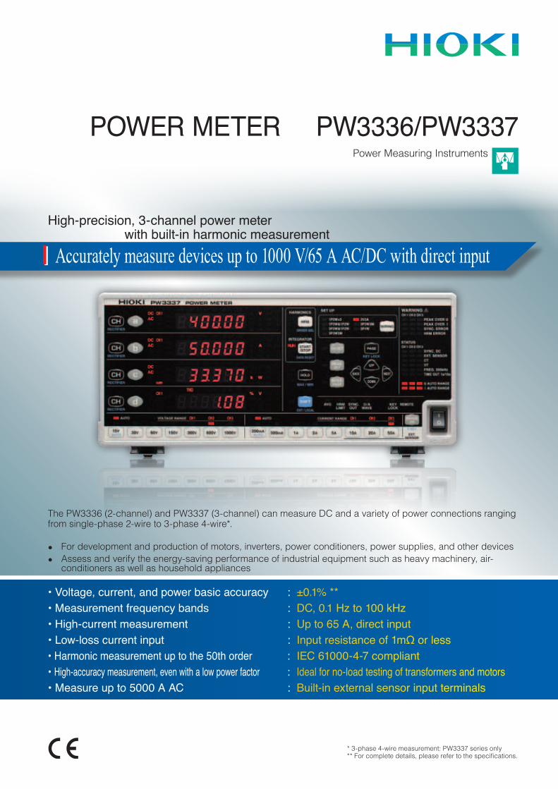
High-precision, 3-channel power meter with built-in harmonic measurement
The PW3336 (2-channel) and PW3337 (3-channel) can measure DC and a variety of power connections ranging from single-phase 2-wire to 3-phase 4-wire*.
Accurately measure devices up to 1000 V/65 A AC/DC with direct input
• For development and production of motors, inverters, power conditioners, power supplies, and other devices• Assess and verify the energy-saving performance of industrial equipment such as heavy machinery, air-
conditioners as well as household appliances
• Voltage, current, and power basic accuracy :• Measurement frequency bands :• High-current measurement :• Low-loss current input :• Harmonic measurement up to the 50th order :• High-accuracy measurement, even with a low power factor :• Measure up to 5000 A AC :
±0.1% **DC, 0.1 Hz to 100 kHzUp to 65 A, direct inputInput resistance of 1mΩ or less IEC 61000-4-7 compliantIdeal for no-load testing of transformers and motorsBuilt-in external sensor input terminals
* 3-phase 4-wire measurement: PW3337 series only**Forcompletedetails,pleaserefertothespecifications.
2
High-accuracyHigh-currentHarmonic measurement
2
±0.1%±0.1% *
Support for development and production of motors, transformers, air-conditioners, and other industrial equipment
Support for development and production of motors, transformers, air-conditioners, and other industrial equipment
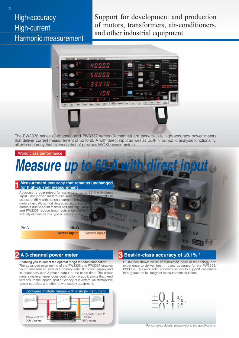
The PW3336 series (2-channel) and PW3337 series (3-channel) are easy-to-use, high-accuracy power meters that deliver current measurement of up to 65 A with direct input as well as built-in harmonic analysis functionality, all with accuracy that exceeds that of previous HIOKI power meters.
Accuracy is guaranteed for currents of up to 65 A with direct input. The power meters can also measure high currents in excess of 65 A with optional current sensors. Direct-input power meters typically exhibit degraded accuracy when inputting high currents due to shunt resistor self-heating. However, the PW3336 and PW3337 reduce input resistance with a DCCT design that virtually eliminates this type of accuracy degradation.
Enabling you to select the optimal range for each connectionThe advanced engineering of the PW3336 and PW3337 enables you to measure an inverter’s primary-side DC power supply and its secondary-side 3-phase output at the same time. The power meters make a tremendous contribution in applications that need tomeasuretheinput/outputefficiencyofinverters,uninterruptiblepower supplies, and other power supply equipment.
HIOKI has drawn on its accumulated base of technology and experience to deliver best-in-class accuracy for the PW3336/PW3337. This rock-solid accuracy serves to support customers throughout the full range of measurement situations.
World class performance
Measure up to 65 A with direct input1 Measurement accuracy that remains unchanged
for high-current measurement
2 A 3-channel power meter 3 Best-in-class accuracy of ±0.1% *
2mA 5000ASensor input
65ADirect input
Channel 3: DC300 V range
Channels 1 and 2: 3P3W60 V range
Configure multiple ranges with a single instrument
*Forcompletedetails,pleaserefertothespecifications.
3
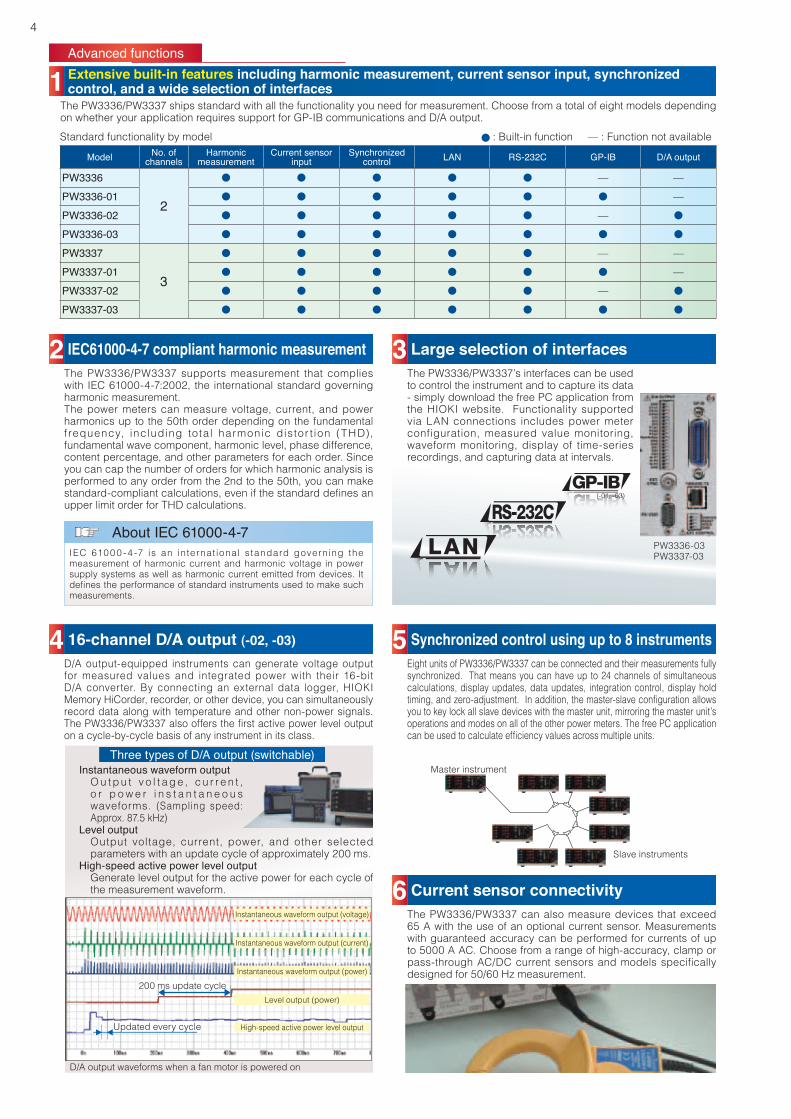
All data, including RMS values, mean values, DC components, AC components, fundamental wave components, harmonic measurement, and integration measurement, is processed in parallel internally. There is no need to switch modes depending on whether you wish to acquire power data or harmonic data-- simply switch the display to obtain measured values with true simultaneity. Additionally, PC communications software can be used to capture measurement data, including from multiple synchronized instruments.
Because power factor has little impact at just ±0.1% f.s., the PW3336/PW3337 can measure active power of low-power-factor input at a high level of accuracy, for example during no-load-loss testing, a technique that is used to evaluate energy-saving performance of transformers.Even though the high current waveform crest factor that typically accompanies no-load operation causes the power factor to deteriorate, measurements taken with the PW3336/PW3337 series remain accurate under these conditions.
Thanks to a wide-band capability extending from DC and 0.1 Hz to 100 kHz, the PW3336/PW3337 can cover not only inverters’ fundamental frequency band, but also the carrier frequency band.
The power consumption of equipment subject to a fluctuating load, for example refrigerators, heaters, and pumps, varies considerably between rated operation and no-load operation. Thanks to its broad dynamic range, the PW3336/PW3337 can perform integrated power measurement with guaranteed accuracy using a single range, even if the power fluctuates dramatically during integration. Measurements can accommodate waveform peaks of up to 600% of the range rating.
Voltage RMS value
Voltage mean value
Voltage fundamental wave component
Total harmonic distortion (THD)
Simultaneous processing of all data
World class performance
4 Simultaneous processing of power data and all harmonic data 5 High-accuracy measurement, even with low-
power-factor input
6 Wide frequency band of DC and 0.1 Hz to 100 kHz 7 Integrating fluctuating power values
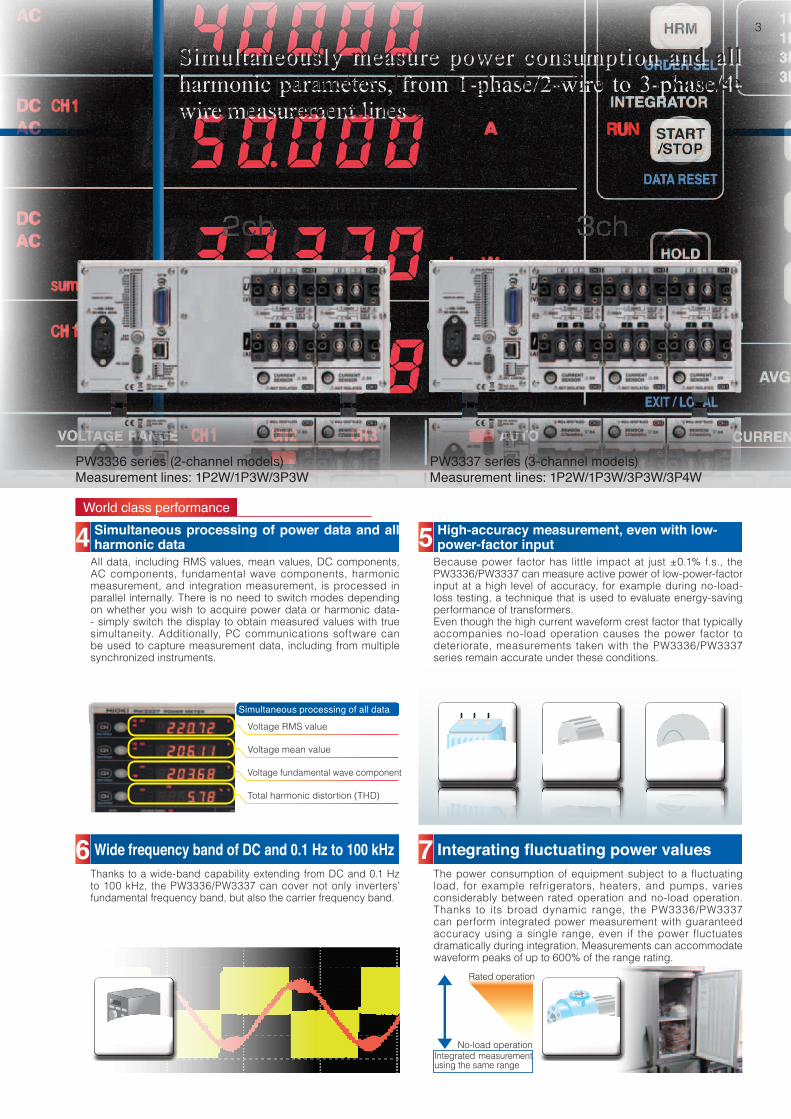
Simultaneously measure power consumption and all harmonic parameters, from 1-phase/2-wire to 3-phase/4-wire measurement lines
Simultaneously measure power consumption and all harmonic parameters, from single-phase 2-wire to 3-phase 4-wire measurement lines
PW3336 series (2-channel models)Measurement lines: 1P2W/1P3W/3P3W
PW3337 series (3-channel models)Measurement lines: 1P2W/1P3W/3P3W/3P4W
Integrated measurement using the same range
Rated operation
No-load operation
4
(-01, -03)
Advanced functions
1 Extensive built-in features including harmonic measurement, current sensor input, synchronized control, and a wide selection of interfaces
The PW3336/PW3337 ships standard with all the functionality you need for measurement. Choose from a total of eight models depending on whether your application requires support for GP-IB communications and D/A output.
Standard functionality by model : Built-in function — : Function not available
Model No. of channels
Harmonic measurement
Current sensor input
Synchronized control LAN RS-232C GP-IB D/A output
PW3336
2
— —
PW3336-01 —
PW3336-02 —
PW3336-03PW3337
3
— —
PW3337-01 —
PW3337-02 —
PW3337-03
4 16-channel D/A output (-02, -03)
6 Current sensor connectivity
5 Synchronized control using up to 8 instruments
3 Large selection of interfaces2 IEC61000-4-7 compliant harmonic measurementThe PW3336/PW3337 supports measurement that complies with IEC 61000-4-7:2002, the international standard governing harmonic measurement. The power meters can measure voltage, current, and power harmonics up to the 50th order depending on the fundamental f requency, including total harmonic distor t ion (THD), fundamental wave component, harmonic level, phase difference, content percentage, and other parameters for each order. Since you can cap the number of orders for which harmonic analysis is performed to any order from the 2nd to the 50th, you can make standard-compliantcalculations,evenifthestandarddefinesanupper limit order for THD calculations.
D/A output-equipped instruments can generate voltage output for measured values and integrated power with their 16-bit D/A converter. By connecting an external data logger, HIOKI Memory HiCorder, recorder, or other device, you can simultaneously record data along with temperature and other non-power signals. ThePW3336/PW3337alsooffersthefirstactivepowerleveloutputon a cycle-by-cycle basis of any instrument in its class.
Eight units of PW3336/PW3337 can be connected and their measurements fully synchronized. That means you can have up to 24 channels of simultaneous calculations, display updates, data updates, integration control, display hold timing,andzero-adjustment.Inaddition,themaster-slaveconfigurationallowsyou to key lock all slave devices with the master unit, mirroring the master unit’s operations and modes on all of the other power meters. The free PC application canbeusedtocalculateefficiencyvaluesacrossmultipleunits.
The PW3336/PW3337 can also measure devices that exceed 65 A with the use of an optional current sensor. Measurements with guaranteed accuracy can be performed for currents of up to 5000 A AC. Choose from a range of high-accuracy, clamp or pass-through AC/DC current sensors and models specifically designed for 50/60 Hz measurement.
Slave instruments
Master instrument
The PW3336/PW3337’s interfaces can be used to control the instrument and to capture its data - simply download the free PC application from the HIOKI website. Functionality supported via LAN connections includes power meter configuration, measured value monitoring, waveform monitoring, display of time-series recordings, and capturing data at intervals.
PW3336-03PW3337-03IEC 610 0 0 - 4 -7 is an internat ional standard governing the
measurement of harmonic current and harmonic voltage in power supply systems as well as harmonic current emitted from devices. It definestheperformanceofstandardinstrumentsusedtomakesuchmeasurements.
About IEC 61000-4-7
Instantaneous waveform outputO u t p u t v o l t a g e , c u r r e n t , o r p o w e r i n s t a n t a n e o u s waveforms. (Sampling speed: Approx. 87.5 kHz)
Level outputOutput voltage, current, power, and other selected parameters with an update cycle of approximately 200 ms.
High-speed active power level outputGenerate level output for the active power for each cycle of the measurement waveform.
Three types of D/A output (switchable)
Instantaneous waveform output (voltage)
Instantaneous waveform output (current)
Instantaneous waveform output (power)
Level output (power)
Updated every cycle High-speed active power level output
D/A output waveforms when a fan motor is powered on
200 ms update cycle
5
Applications
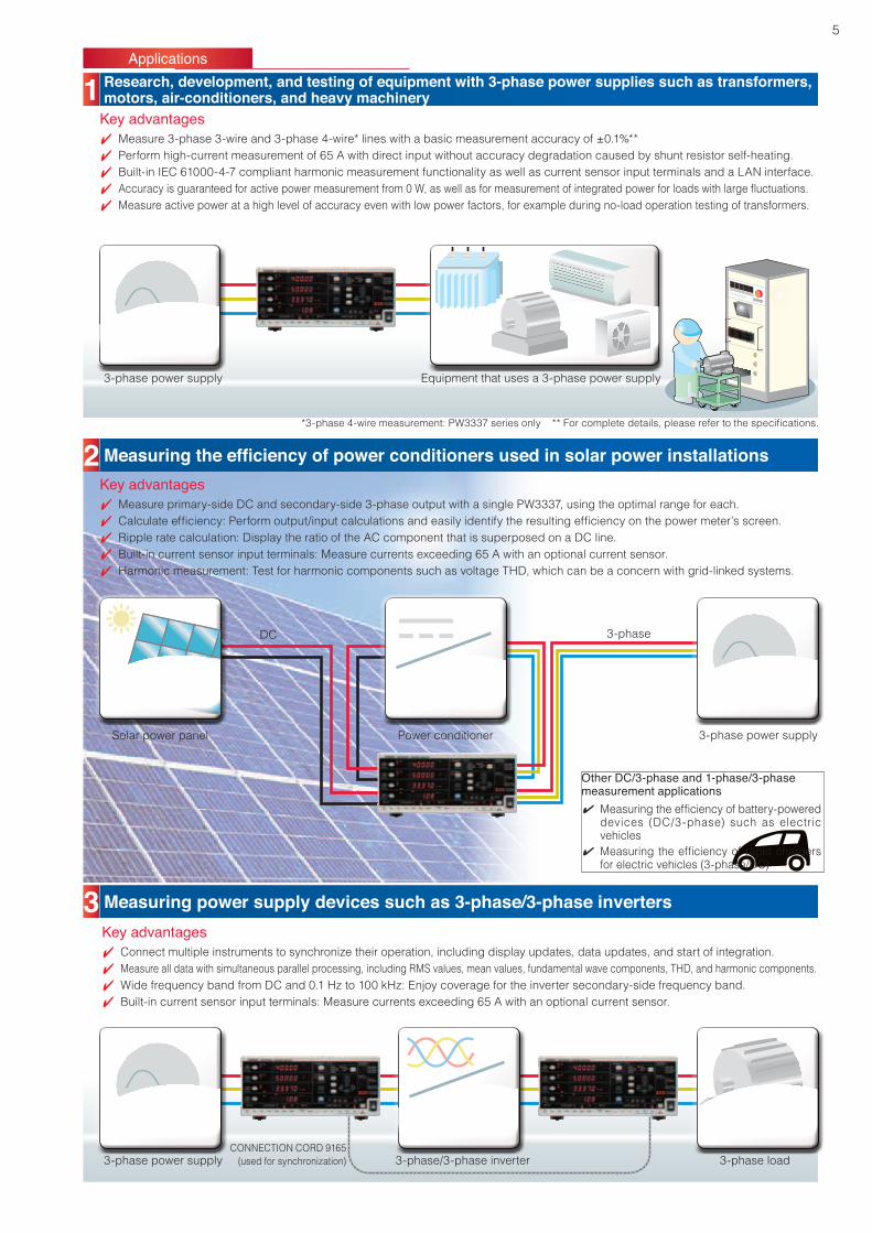
1 Research, development, and testing of equipment with 3-phase power supplies such as transformers, motors, air-conditioners, and heavy machinery
2 Measuring the efficiency of power conditioners used in solar power installations
3 Measuring power supply devices such as 3-phase/3-phase inverters
3-phase power supply
Solar power panel
DC 3-phase
Power conditioner
3-phase/3-phase inverterCONNECTION CORD 9165
(used for synchronization) 3-phase load
3-phase power supply
3-phase power supply
Equipment that uses a 3-phase power supply
Key advantages4 Measure 3-phase 3-wire and 3-phase 4-wire* lines with a basic measurement accuracy of ±0.1%**
4 Perform high-current measurement of 65 A with direct input without accuracy degradation caused by shunt resistor self-heating.
4 Built-in IEC 61000-4-7 compliant harmonic measurement functionality as well as current sensor input terminals and a LAN interface.
4 Accuracyisguaranteedforactivepowermeasurementfrom0W,aswellasformeasurementofintegratedpowerforloadswithlargefluctuations.
4 Measure active power at a high level of accuracy even with low power factors, for example during no-load operation testing of transformers.
Key advantages4 Measure primary-side DC and secondary-side 3-phase output with a single PW3337, using the optimal range for each.
4 Calculateefficiency:Performoutput/inputcalculationsandeasilyidentifytheresultingefficiencyonthepowermeter’sscreen.
4 Ripple rate calculation: Display the ratio of the AC component that is superposed on a DC line.
4 Built-in current sensor input terminals: Measure currents exceeding 65 A with an optional current sensor.
4 Harmonic measurement: Test for harmonic components such as voltage THD, which can be a concern with grid-linked systems.
Key advantages4 Connect multiple instruments to synchronize their operation, including display updates, data updates, and start of integration.
4 Measure all data with simultaneous parallel processing, including RMS values, mean values, fundamental wave components, THD, and harmonic components.
4 Wide frequency band from DC and 0.1 Hz to 100 kHz: Enjoy coverage for the inverter secondary-side frequency band.
4 Built-in current sensor input terminals: Measure currents exceeding 65 A with an optional current sensor.
*3-phase 4-wire measurement: PW3337 series only **Forcompletedetails,pleaserefertothespecifications.
Other DC/3-phase and 1-phase/3-phasemeasurement applications4 Measuringtheefficiencyofbattery-powered
devices (DC/3-phase) such as electric vehicles
4 Measuringtheefficiencyof rapidchargersfor electric vehicles (3-phase/DC)
6
Applications
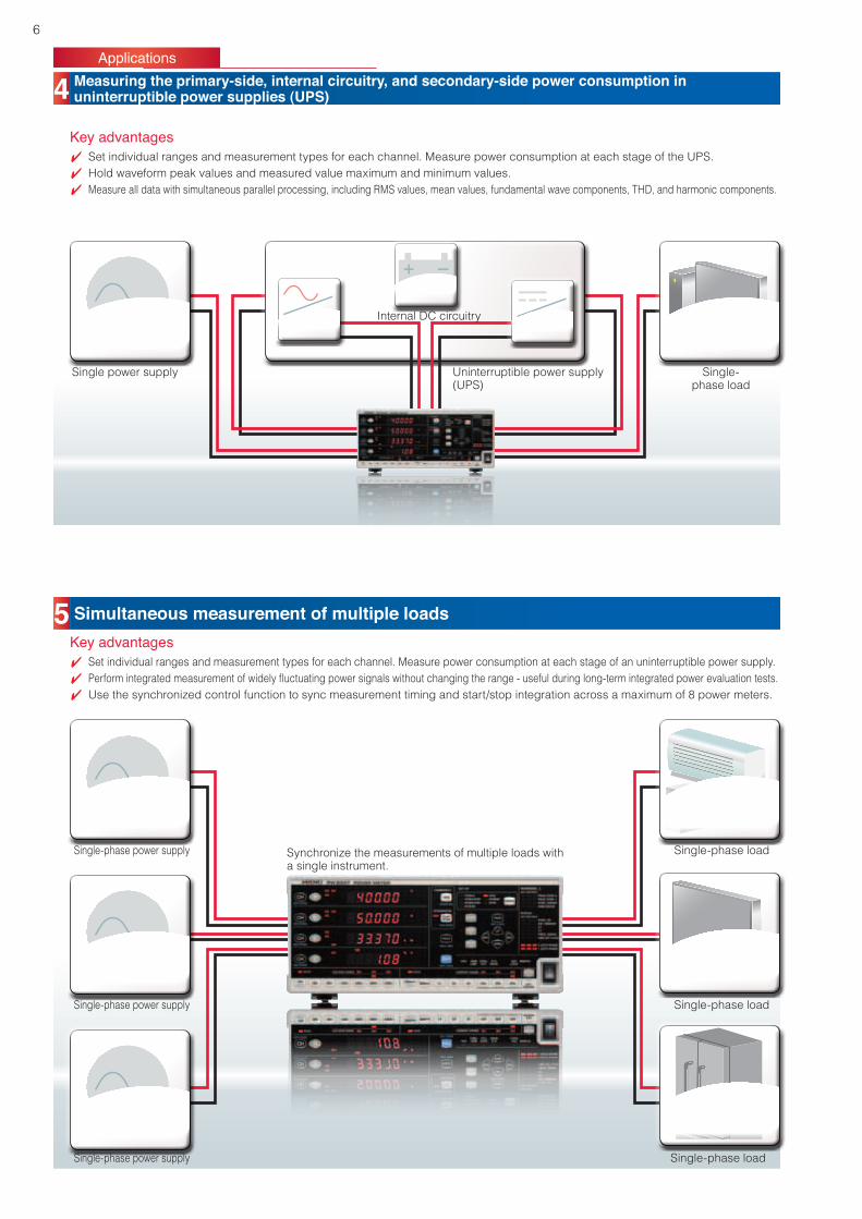
4 Measuring the primary-side, internal circuitry, and secondary-side power consumption in uninterruptible power supplies (UPS)
5 Simultaneous measurement of multiple loads
Key advantages4 Set individual ranges and measurement types for each channel. Measure power consumption at each stage of the UPS.
4 Hold waveform peak values and measured value maximum and minimum values.
4 Measure all data with simultaneous parallel processing, including RMS values, mean values, fundamental wave components, THD, and harmonic components.
Key advantages4 Set individual ranges and measurement types for each channel. Measure power consumption at each stage of an uninterruptible power supply.
4 Performintegratedmeasurementofwidelyfluctuatingpowersignalswithoutchangingtherange-usefulduringlong-termintegratedpowerevaluationtests.
4 Use the synchronized control function to sync measurement timing and start/stop integration across a maximum of 8 power meters.
Single power supply
Single-phase power supply
Single-phase power supply
Single-phase power supply
Synchronize the measurements of multiple loads with a single instrument.
Internal DC circuitry
Uninterruptible power supply(UPS)
Single-phase load
Single-phase load
Single-phase load
Single-phase load
7
Software
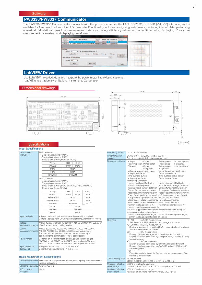
Dimensional drawings
PW3336/PW3337 Communicator
LabVIEW Driver
The PW3336/PW3337 Communicator connects with the power meters via the LAN, RS-232C, or GP-IB (-01, -03) interface, and is availableforfreedownloadfromtheHIOKIwebsite.Functionalityincludesconfiguringinstruments,capturingintervaldata,performingnumerical calculations based on measurement data, calculating efficiency values across multiple units, displaying 10 or more measurement parameters, and displaying waveforms.
Use LabVIEW* to collect data and integrate the power meter into existing systems.*LabVIEW is a trademark of National Instruments Corporation.
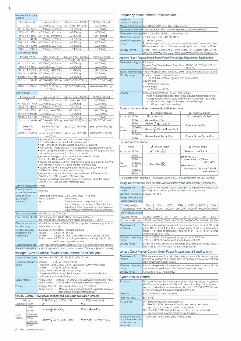
(Unit: mm)SpecificationsInput SpecificationsMeasurementline type
PW3336 series Single-phase 2-wire (1P2W), Single-phase 3-wire (1P3W), Three-phase 3-wire (3P3W, 3P3W2M)
Wiring CH1 CH21P2W×2 1P2W 1P2W
1P3W 1P3W3P3W 3P3W
3P3W2M 3P3W2M
PW3337 series Single-phase 2-wire (1P2W), Single-phase 3-wire (1P3W), Three-phase 3-wire (3P3W, 3P3W2M, 3V3A, 3P3W3M), Three-phase 4-wire (3P4W)
Wiring CH1 CH2 CH31P2W×3 1P2W 1P2W 1P2W
1P3W&1P2W 1P3W 1P2W3P3W&1P2W 3P3W 1P2W
3P3W2M 3P3W2M3V3A 3V3A
3P3W3M 3P3W3M3P4W 3P4W
Input methods Voltage Isolated input, resistance voltage division methodCurrent Isolated input, DCCT method Isolated input from current sensors
Voltagemeasurement ranges
AUTO/ 15.000 V/ 30.000 V/ 60.000 V/ 150.00 V/ 300.00 V/ 600.00 V/ 1000.0 V (set for each wiring mode)
Currentmeasurement ranges
AUTO/ 200.00 mA/ 500.00 mA/ 1.0000 A/ 2.0000 A/ 5.0000 A/ 10.000 A/ 20.000 A/ 50.000 A (set for each wiring mode)For more information about external current sensor input,seetheexternalcurrentsensorinputspecifications
Power ranges Depends on the combination of voltage and current ranges;PW3336: from 3.0000W to 100.00kW (also applies to VA, var) PW3337: from 3.0000W to 150.00kW (also applies to VA, var)
Input resistance (50/60 Hz)
Voltageinputterminal :2MΩ±0.04MΩCurrentdirectinputterminal:1mΩorless
Frequency bands DC, 0.1 Hz to 100 kHz
Synchronizationsources
U1,U2,U3,I1,I2,I3,DC(fixedat200ms)Can be set separately for each wiring mode.
Measurement items · Voltage · Current · Active power · Apparent power · Reactive power · Power factor · Phase angle · Frequency · Efficiency · Current
integration · Active power integration
· Integrated time
· Voltage waveform peak value · Current waveform peak value · Voltage crest factor · Current crest factor · Time average current · Time average active power · Voltage ripple factor · Current ripple factorHarmonic parameters: · Harmonic voltage RMS value · Harmonic current RMS value · Harmonic active power · Total harmonic voltage distortion · Total harmonic current distortion · Voltage fundamental waveform · Current fundamental waveform · Active power fundamental waveform · Apparent power fundamental waveform · Reactive power fundamental waveform · Power factor fundamental waveform (displacement power factor) · Voltage current phase difference fundamental waveform · Interchannel voltage fundamental wave phase difference · Interchannel current fundamental wave phase difference · Harmonic voltage content % · Harmonic current content % · Harmonic active power content %The following parameters can be downloaded as data during PC communication but not displayed: · Harmonic voltage phase angle · Harmonic current phase angle · Harmonic voltage current phase difference
Rectifiers AC+DC : AC+DC measurement Display of true RMS values for both voltage and currentAC+DC Umn : AC+DC measurement DisplayofaveragevaluerectifiedRMSconvertedvaluesforvoltage and true RMS values for currentDC : DC measurement Display of simple averages for both voltage and current Display of values calculated by (voltage DC value)× (current DC value) for active powerAC : AC measurement Display of values calculated by for both voltage and current Display of values calculated by (AC+DC value)2 - (DC value)2
for active powerFND Extraction and display of the fundamental wave component from harmonic measurement
Zero-Crossing Filter 500 Hz/200 kHz500 Hz: 0.1 Hz to 500 Hz, 200 kHz: 0.1 Hz to 200 kHz
Maximum effectivepeak voltage
±600% of each voltage rangeHowever, for 300 V, 600 V, and 1000 V ranges, ±1500 Vpeak
Maximum effectivepeak current
±600% of each current rangeHowever, for 20 A range and 50 A range, ±100 Apeak
Basic Measurement SpecificationsMeasurement method Simultaneous voltage and current digital sampling, zero-cross simul-
taneous calculationSampling frequency Approx. 700 kHz
A/D converterresolution
16-bit
8
Measurement accuracy
Guaranteed accuracy period 1 yearPost-adjustment accuracy guaranteed 6 months
Conditions ofguaranteedaccuracy
Temperature and humidity : 23°C ±5°C, 80% RH or lessWarm-up time : 30 minutesInput : Sine wave input, power factor of 1, terminal-to-ground voltage of 0V, after zero adjustment; within range in which the fundamental wavesatisfiessynchronizationsourceconditions
Temperature characteristic ±0.03% f.s. per °C or lessPower factor effects ±0.1% f.s. or less (45 to 66 Hz, at power factor = 0)
Internal circuitry voltage/current phase difference: ±0.0573°Effect of commonmode voltage
±0.02% f.s. or less (600 V, 50/60 Hz, applied between input termi-nals and enclosure)
Effect of externalmagneticfieldinterference
400A/m,DCand50/60HzmagneticfieldVoltage :±1.5% f.s. or lessCurrent :±1.5% f.s. or ±10 mA, whichever is greater, or lessActivepower:±3.0%f.s.or(voltageinfluencequantity)×(±10mA), whichever is greater, or less
Magnetization effect ±10 mA equivalent or less (after inputting 100 A DC to the current direct input terminals)Adjacent channel input effect ±10 mA equivalent or less (when inputting 50 A to adjacent channel)
Voltage
Frequency (f) Input < 50% f.s. 50%f.s.≤Input<100%f.s. 100%f.s.≤InputDC ±0.1%rdg. ±0.1%f.s. ±0.1%rdg. ±0.1%f.s. ±0.2%rdg.
0.1Hz≤f<16Hz ±0.1%rdg. ±0.2%f.s. ±0.3%rdg. ±0.3%rdg.16Hz≤f<45Hz ±0.1%rdg. ±0.1%f.s. ±0.2%rdg. ±0.2%rdg.45Hz≤f≤66Hz ±0.1%rdg. ±0.05%f.s. ±0.15%rdg. ±0.15%rdg.66Hz<f≤500Hz ±0.1%rdg. ±0.1%f.s. ±0.2%rdg. ±0.2%rdg.500Hz<f≤10kHz ±0.1%rdg. ±0.2%f.s. ±0.3%rdg. ±0.3%rdg.10kHz<f≤50kHz ±0.5%rdg. ±0.3%f.s. ±0.8%rdg. ±0.8%rdg.50kHz<f≤100kHz ±2.1%rdg. ±0.3%f.s. ±2.4%rdg. ±2.4%rdg.
Current (direct input)
Frequency (f) Input < 50% f.s. 50%f.s.≤Input<100%f.s. 100%f.s.≤InputDC ±0.1%rdg. ±0.1%f.s. ±0.1%rdg. ±0.1%f.s. ±0.2%rdg.
0.1Hz≤f<16Hz ±0.1%rdg. ±0.2%f.s. ±0.3%rdg. ±0.3%rdg.16Hz≤f<45Hz ±0.1%rdg. ±0.1%f.s. ±0.2%rdg. ±0.2%rdg.45Hz≤f≤66Hz ±0.1%rdg. ±0.05%f.s. ±0.15%rdg. ±0.15%rdg.66Hz<f≤500Hz ±0.1%rdg. ±0.1%f.s. ±0.2%rdg. ±0.2%rdg.500Hz<f≤1kHz ±0.1%rdg. ±0.2%f.s. ±0.3%rdg. ±0.3%rdg.1kHz<f≤10kHz ±(0.03+0.07×F)%rdg.
±0.2%f.s.±(0.23+0.07×F)%rdg. ±(0.23+0.07×F)%rdg.
10kHz<f≤100kHz ±(0.3+0.04×F)%rdg.±0.3%f.s.
±(0.6+0.04×F)%rdg. ±(0.6+0.04×F)%rdg.
Active power
Frequency (f) Input < 50% f.s. 50%f.s.≤Input<100%f.s. 100%f.s.≤InputDC ±0.1%rdg. ±0.1%f.s. ±0.1%rdg. ±0.1%f.s. ±0.2%rdg.
0.1Hz≤f<16Hz ±0.1%rdg. ±0.2%f.s. ±0.3%rdg. ±0.3%rdg.16Hz≤f<45Hz ±0.1%rdg. ±0.1%f.s. ±0.2%rdg. ±0.2%rdg.45Hz≤f≤66Hz ±0.1%rdg. ±0.05%f.s. ±0.15%rdg. ±0.15%rdg.66Hz<f≤500Hz ±0.1%rdg. ±0.1%f.s. ±0.2%rdg. ±0.2%rdg.500Hz<f≤1kHz ±0.1%rdg. ±0.2%f.s. ±0.3%rdg. ±0.3%rdg.1kHz<f≤10kHz ±(0.03+0.07×F)%rdg.
±0.2%f.s.±(0.23+0.07×F)%rdg. ±(0.23+0.07×F)%rdg.
10kHz<f≤50kHz
±(0.07×F)%rdg.±0.3%f.s.
±(0.3+0.07×F)%rdg. ±(0.3+0.07×F)%rdg.
50kHz<f≤100kHz ±(0.6+0.07×F)%rdg.±0.3%f.s.
±(0.9+0.07×F)%rdg. ±(0.9+0.07×F)%rdg.
•Valuesforf.s.dependonmeasurementranges.•“F”inthetablesreferstothefrequencyinkHz.•Add±1mAtoDCmeasurementaccuracyforcurrent.•Add (±1mA) × (voltage read value) to DC measurement accuracy for active power.•Whenusingthe200mAor500mArange,add±0.1%rdg.tocurrentandactivepowerforwhich1kHz<f≤10kHz.•Valuesforvoltage,current,andactivepowerforwhich 0.1Hz≤f<10Hzareforreferenceonly.•Valuesforvoltage,current,andactivepower inexcessof220Vor20Aforwhich10Hz≤f<16Hzareforreferenceonly.•Valuesforcurrentandactivepowerinexcessof20Aforwhich 500Hz<f≤50kHzareforreferenceonly.•Valuesforcurrentandactivepowerinexcessof15Aforwhich 50kHz<f≤100kHzareforreferenceonly.•Valuesforvoltageandactivepowerinexcessof750Vforwhich 30kHz<f≤100kHzareforreferenceonly.
Voltage/ Current/ Active Power Measurement SpecificationsMeasurement types Rectifiers:AC+DC,DC,AC,FND,AC+DCUmn
Effective measuringrange
Voltage : 1% to 130% of range (however, up to ±1500 V peak value and 1000 V RMS value)Current : 1% to 130% of rangeActive power : 0% to 169% of the range (However, defined when the voltage and current fall within the effective measurement range.)
Display range Voltage/ Current : 0.5% to 140% of range (zero-suppression when less than 0.5%)Active power : 0% to 196% of the range (no zero-suppression)
Polarity Voltage/Current:DisplayedwhenusingDCrectifierActive power +: Positive: Power consumption (no polarity display) -: generation or regenerated power
Voltage/ Current/ Active power channel and sum value calculation formulasWiring X: U (Voltage) or I (Current) P (Active power)
All channels 1P2W
Sumvalues
1P3W3P3W3P3W2M3V3A3P3W3M3P4W
( i ): Measurement channel
X( i ) P( i )
21Xsum = (X(1) + X(2)) Psum = (P(1) + P(2))
31Xsum = (X( 1 ) + X( 2 ) + X( 3 )) Psum = (P( 1 ) + P( 2 ) + P( 3 ))
Power channel and sum value calculation formulasWiring S : Apparent power Q : Reactive power
All channels 1P2W
Sumvalues
1P3W3P3W3P3W2M3V3A3P3W3M3P4W
( i ): Measurement channel
Ssum = S( 1 ) + S( 2 ) + S( 3 )
Ssum = S( 1 ) + S( 2 )
Qsum = Q( 1 ) + Q( 2 ) + Q( 3 )
Qsum = Q( 1 ) + Q( 2 )
S( i ) = U( i ) I( i ) Q( i ) = si( i ) S( i )2 - P( i )2
33Ssum = (S( 1 ) + S( 2 ) + S( 3 ))
23Ssum = (S( 1 ) + S( 2 ))
Wiring : Power factor : Phase angle
All channels 1P2W
Sumvalues
1P3W3P3W3P3W2M3V3A3P3W3M3P4W
( i ): Measurement channel ; The polarity symbol sisum is acquired from the Qsum symbol.
S( i )P( i )si( i )( i ) =
SsumPsumsisumsum =
( i ) = si( i ) cos-1| ( i )|
sum = sisum cos-1| sum|(0º to ±90º)
When Psum ≥ 0
When Psum ≥ 0
(±90º to ±180º)sum = sisum |180 - cos-1| sum||
Frequency Measurement SpecificationsNumber ofmeasurement channels
3
Measurement source Select from U (VHz) or I (AHz) by channelMeasurement method Calculated from input waveform period (reciprocal method)
Measurement range 500Hz/200kHz(linkedtozero-crossfilter)Measurement accuracy ±0.1% rdg. ±1 dgt. (0°C to 40°C)Effective measuringrange
0.1 Hz to 100 kHzFor sine wave input that is at least 20% of the measurement source’s measurement range.Measurement lower limit frequency setting: 0.1 sec. / 1 sec. / 10 sec.
Display format 0.1000 Hz to 9.9999 Hz, 9.900 Hz to 99.999 Hz, 99.00 Hz to 999.99 Hz,9900 kHz to 9.9999 kHz, 9.900 kHz to 99.999 kHz, 99.00 kHz to 220.00 kHz
Apparent Power/ Reactive Power/ Power Factor/ Phase Angle Measurement SpecificationsMeasurement types Rectifiers
Apparent Power/ Reactive Power/ Power Factor : AC+DC, AC, FND, AC+DC UmnPhase Angle : AC, FND
Effective measuring range As per voltage, current, and active power effective measurement ranges.Display range Apparent Power/ Reactive Power
: 0% to 196% of the range (no zero-suppression)Power Factor : ±0.0000 to ±1.0000Phase Angle : +180.00 to -180.00
Polarity Reactive Power/ Power Factor/ Phase Angle Polarity is assigned according to the lead/lag relationship of the voltage waveform rising edge and the current waveform rising edge. + : When current lags voltage (no polarity display) - : When current leads voltage
Voltage Crest Factor/ Current Crest Factor Measurement SpecificationsMeasurementmethod
Calculates values from display values once each display update interval for voltage and voltage waveform peak values or current and current waveform peak values.
Effective measuringrange
As per voltage and voltage waveform peak value or current and cur-rent waveform peak value effective measurement ranges.
Display range 1.0000 to 612.00 (no polarity)
Voltage Waveform Peak Value / Current Waveform Peak Value Measurement SpecificationsMeasurementmethod
Measures the waveform’s peak value (for both positive and negative polarity) based on sampled instantaneous voltage values.
Sampling frequency Approx. 700 kHzRangeconfiguration
Measurementaccuracy
Same as the voltage or current measurement accuracy at DC and when10Hz≤ f≤1kHz(f.s.:voltagepeakrangeorcurrentpeakrange).Providedasreferencevaluewhen0.1Hz≤ f<10Hzandwhen in excess of 1 kHz.
Effective measuring range
±5% to ±100% of voltage peak range (up to ±1500 V) or±5% to ±100% of current peak range (up to ±100 A)
Display range ±0.3% to ±102% of voltage peak range or current peak range (values less than ±0.3% are subject to zero-suppression)
Voltage peak range
Voltage range 15V 30V 60V 150V 300V 600V 1000VVoltage peak range 90.000V 180.00V 360.00V 900.00V 1.8000kV 3.6000kV 6.0000kV
Current peak range
Current range 200mA 500mA 1A 2A 5A 10A 20A 50ACurrent peak range 1.2000A 3.0000A 6.0000A 12.000A 30.000A 60.000A 120.00A 300.00A
Synchronized ControlFunctions Timing of calculations, display updates, data updates, integration
start/stop/reset events, display hold operation, key lock operation, and zero-adjustment operation for the slave PW3336/PW3337 are synchronized with the master PW3336/PW3337.
Terminal BNC terminal × 1 (non-isolated)
Terminal name EXT SYNC
I/O settings Off : Synchronized control function offIn : The EXT SYNC terminal is set to input, and a dedicated synchronization signal can be input (slave). Out: The EXT SYNC terminal is set to output, and a dedicated synchronization signal can be output (master).
Number of units forwhich synchronizedcontrol can beperformed
1 master unit and 7 slave units (total 8 units)
9
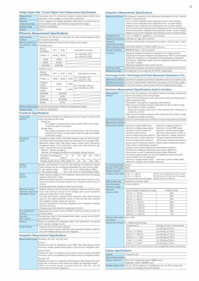
Voltage Ripple Rate / Current Ripple Factor Measurement SpecificationsMeasurementmethod
Calculates the AC component (peak to peak [peak width]) as a proportion of the voltage or current DC component
Effectivemeasuring range
As per voltage and voltage waveform peak value or current and cur-rent waveform peak value effective measurement ranges
Display range 0.00[%] to 500.00[%]Polarity None
Efficiency Measurement SpecificationsMeasurementmethod
Calculatestheefficiencyh [%] from the ratio of active power values for channels and wires
Wiring modes andcalculation equa-tions
CalculatedbasedontheAC+DCrectifieractivepower
Effective measuring range As per the active power effective measurement range.Display range 0.00[%] to 200.00[%]
PW3337 series
Wiring(WIRING) CH1 CH2 CH3 Calculation formulas
1P2W × 3 1P2W 1P2W 1P2W h1=100×|P3| / |P1|h2=100×|P1| / |P3|
1P3W &1P2W 1P3W 1P2W
h1=100×|P3| / |Psum|h2=100×|Psum| / |P3|3P3W &
1P2W 3P3W 1P2W
3P3W2M 3P3W2M3V3A 3V3A3P3W3M 3P3W3M3P4W 3P4W
PW3336 series
Wiring(WIRING) CH1 CH2 Calculation formulas
1P2W × 2 1P2W 1P2W h1=100×|P2| / |P1|h2=100×|P1| / |P2|
1P3W 1P3W3P3W 3P3W
3P3W2M 3P3W2M
Functional SpecificationsAuto-range(AUTO)
Automatically changes the voltage and current range for each wiring mode according to the input Range up : The range is increased when input exceeds 130% of the range or when the peak is exceeded. Range down : The range is decreased when input falls below 15% of the range. However, the range is not decreased when the peak is exceeded at the lower range.
Averaging(AVG)
· Averages the voltage, current, active power, apparent power, and reactive power. · The power factor and phase angle are calculated from averaged data. · Measured values other than peak values, power factor, frequency, integrated values, T.AV, crest factor, ripple rate, total harmonic dis-tortion, and harmonics are averaged.
Method : Simple averaging Number of averaging iterations and display update interval
Scaling(VT, CT)
Appliesuser-definedVTandCTratiosettingstomeasuredvalues.Thesesettingscanbeconfiguredseparatelyforeachwiringmode.VT ratio setting range : OFF (1.0), 0.1 to 1000 (setting: 0000)CT ratio setting range : OFF (1.0), 0.001 to 1000 (setting: 0000)
HOLD(HOLD)
· Stopsdisplayupdatesforallmeasuredvaluesandfixesthedisplayvalues at that point in time.
· Measurementdataacquiredbycommunicationsisalsofixedatthatpointintime. · Internal calculations (including integration and integration elapsed time) will continue. · Analog output and waveform output are not held.
Maximum value/minimum value hold(MAX/MIN HOLD)
· Detects maximum and minimum measured values as well as maxi-mum and minimum values for the voltage and current waveform peak and holds them on the display. · For data with polarity, display of the maximum value and minimum value for the data’s absolute values is held (so that both positive and negative polarity values are shown). · Internal calculations (including integration and integration elapsed time) will continue. · Analog output and waveform output are not held.
Zero Adjustment(0 ADJ)
Degausses the current input unit DCCT and then zeroes out the cur-rent input offset.
Key-lock(KEY LOCK)
Disables key input in the measurement state, except for the SHIFT key and KEY LOCK key.
Backup Backs up settings and integration data if the instrument is turned off and if a power outage occurs.
System Reset · Initializes the instrument’s settings. · Communications-related settings (communications speed, address, and LAN-related settings) are not initialized.
Number of averaging iterations
1(OFF)
2 5 10 25 50 100
Display update interval 200ms 400ms 1s 2s 5s 10s 20s
Integration Measurement SpecificationsMeasurement items Simultaneous integration of the following 6 parameters for each channel
(total of 18 parameters):Sum of current integrated values (displayed as Ah on panel display)Positive current integrated value (displayed as Ah+ on panel display)Negative current integrated value (displayed as Ah- on panel display)Sum of active power integrated values (displayed as Wh on panel display)Positive active power integrated value (displayed as Wh+ on panel display)Negative active power integrated value (displayed as Wh- on panel display)
Integration time 1 min. to 10000 hr., settable in 1 min. blocksIntegration time accuracy ±100 ppm ±1 dgt. (0°C to 40°C)Integrationmeasurement accuracy
(Current or active power measurement accuracy) + (±0.01% rdg. ±1 dgt.)
Effective measuring range Until PEAK OVER U or PEAK OVER I occursDisplay resolution 999999 (6 digits + decimal point)
Functions · Stopping integration based on integration time setting (timer) · Displaying the integration elapsed time (displayed as TIME on panel display) · Additional integration by repeatedly starting/stopping integration · Backing up integrated values and the integration elapsed time dur-ing power outages · Stopping integration when power returns
External control Stopping/starting integration and resetting integrated values based on external controlMeasuring range Corresponds to the range set for START integretation
Integration Measurement SpecificationsMeasurement types Rectifiers:AC+DC,AC+DCUmn
Current:Displays the result of integrating current RMS value data (display values) once every display update interval (approx. 200 ms) as an integrated value.
Active power:Displays the result of integrating active power values by polarity calculated once every cycle for the selected synchronization source as integrated values.
Rectifier:DCDisplays the result of integrating instantaneous data obtained by sam-pling both current and active power by polarity as integrated values(When the active power contains both AC and DC, the DC component will not be integrated)
Time Average Current / Time Average Active Power Measurement Specifications (T.AV)Measurement method Calculates the average by dividing the integrated value by the integration timeMeasurement accuracy ±(Current or active power measurement accuracy) ±(±0.01%rdg. ±1dgt.)Effective measuring range As per the current or active power effective measurement range
Harmonic Measurement Specifications (built-in function)Measurementmethod
· Zero-cross simultaneous calculation method (separate windows by channel according to the wiring mode) · Uniform thinning between zero-cross events after processing with a digitalantialiasingfilter · Interpolation calculations (Lagrange interpolation) · When the synchronization frequency falls within the 45 Hz to 66 Hz range
» IEC 61000-4-7:2002 compliant » Gaps and overlaps may occur if the measurement frequency is not 50 Hz or 60 Hz
· When the synchronization frequency falls outside the 45 Hz to 66 Hz range » No gaps or overlap will occur
Synchronization source Conformstosynchronizationsource(SYNC)forthebasicmeasurementspecificationsMeasurement channels 3Measurement items ·Harmonic voltage RMS value ·Harmonic voltage content %
·Harmonic voltage phase angle ·Harmonic current RMS value ·Harmonic current content % ·Harmonic current phase angle ·Harmonic active power ·Harmonic active power content % · Harmonic voltage current phase difference ·Total harmonic voltage distortion ·Total harmonic current distortion ·Voltage fundamental waveform ·Current fundamental waveform · Active power fundamental waveform ·Apparent power fundamental waveform ·Reactive power fundamental waveform ·Power factor fundamental waveform ·Voltage current phase difference fundamental waveform ·Interchannel voltage fundamental wave phase difference ·Interchannel current fundamental wave phase differenceThe following parameters can be downloaded as data during PC communication but not displayed: · Harmonic voltage phase angle · Harmonic current phase angle · Harmonic voltage current phase difference
FFT processing word length 32 bitsNumber of FFT points 4096Window function RectangularAnalysis window width 45Hz≤f<56Hz 178.57msto222.22ms(10cycles)
56Hz≤f<66Hz 181.82msto214.29ms(12cycles)Frequencies other than the above 185.92 ms to 214.08 ms
Data update rate Depends on window widthSynchronizationfrequency range
10 Hz to 640 Hz
Maximumanalysis order
Analysis order upperlimit setting
2nd to 50th
Measurement accuracy f.s.: Measurement range
For DC, add ±1 mA to current and (±1 mA) × (voltage read value) to active power.
Synchronization frequency (f) range Analysis order10Hz≤f<45Hz 50th45Hz≤f<56Hz 50th56Hz≤f≤66Hz 50th66Hz<f≤100Hz 50th100Hz<f≤200Hz 40th200Hz<f≤300Hz 25th300Hz<f≤500Hz 15th500Hz<f≤640Hz 11th
Frequency (f) Voltage, Current, Active powerDC ±0.4%rdg.±0.2%f.s.10Hz≤f<30Hz ±0.4%rdg.±0.2%f.s.30Hz≤f≤400Hz ±0.3%rdg.±0.1%f.s.400Hz<f≤1kHz ±0.4%rdg.±0.2%f.s.1kHz<f≤5kHz ±1.0%rdg.±0.5%f.s.5kHz<f≤8kHz ±4.0%rdg.±1.0%f.s.
Display SpecificationsDisplay 7-segment LEDNumber of display parameters 4Display resolution Other than integrated values: 99999 count
Integrated values: 999999 countDisplay update rate 200 ms ±50 ms (approx. 5 updates per sec.) to 20 s (varies with
number of averaging iterations setting)
10
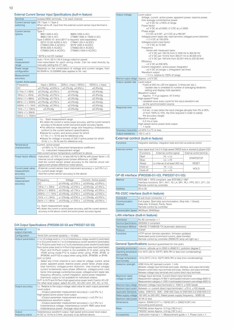
External Current Sensor Input Specifications (built-in feature)Terminal Isolated BNC terminals, 1 for each channelCurrent sensor typeswitching
Off / Type 1 / Type 2When set to off, input from the external current sensor input terminal isignored.
Current sensoroptions
Type 1 9661 (500 A AC) 9669 (1000 A AC) 9660 (100 A AC) CT9667 (500 A / 5000 A AC)Type 2 (9555-10 and L9217 is required; sold separately) 9272-10 (20 A/200 A AC) CT6841 (20 A AC/DC) CT6843 (200 A AC/DC) 9279* (500 A AC/DC) 9709 (500 A AC/DC) CT6862 (50 A AC/DC) CT6863 (200 A AC/DC) CT6865 (1000 A AC/DC)
* 9279 is not CE markedCurrent measurementrange
Auto / 10 A / 20 A / 50 A (range noted on panel)User-selectable for each wiring mode. Can be read directly by manually setting the CT ratio.
Power rangeconfiguration
Depends on the combination of voltage and current ranges; from 60.000W to 15.000MW (also applies to VA, var)
Measurement accuracy
Temperaturecharacteristics
Current, active power :±0.08%f.s./°C(instrumenttemperaturecoefficient; f.s.: instrument measurement range)Addcurrentsensortemperaturecoefficienttoabove.
Power factor effects · Instrument: ±0.15% f.s. or less (45 Hz to 66 Hz with power factor = 0) · Internal circuit voltage/current phase difference: ±0.086° · Add the current sensor phase accuracy to the internal circuit volt-age/current phase difference noted above.
Current peak valuemeasurementaccuracy
· (External current sensor input instrument accuracy) + (±2.0% f.s.)(f.s.:current peak range) · Add the current sensor accuracy to the above.
Harmonicmeasurementaccuracy
Current, Active powerFrequency Input < 50%f.s. 50%f.s.≤Input<100%f.s. 100%f.s.≤InputDC ±0.2%rdg. ±0.6%f.s. ±0.2%rdg. ±0.6%f.s. ±0.8%rdg. 0.1Hz≤f<16Hz ±0.2%rdg. ±0.2%f.s. ±0.4%rdg. ±0.4%rdg. 16Hz≤f<45Hz ±0.2%rdg. ±0.2%f.s. ±0.4%rdg. ±0.4%rdg. 45Hz≤f≤66Hz ±0.2%rdg. ±0.1%f.s. ±0.3%rdg. ±0.3%rdg. 66Hz <f≤500Hz ±0.2%rdg. ±0.2%f.s. ±0.4%rdg. ±0.4%rdg. 500Hz<f≤1kHz ±0.2%rdg. ±0.3%f.s. ±0.5%rdg. ±0.5%rdg. 1kHz<f≤10kHz ±5.0%rdg. ±5.0%rdg. ±5.0%rdg. 10kHz<f≤50kHz50kHz<f≤100kHz
Frequency Voltage Current, Active powerDC ±0.4%rdg. ±0.2%f.s. ±0.6%rdg. ±0.8%f.s.10Hz≤f<30Hz ±0.4%rdg. ±0.2%f.s. ±0.6%rdg. ±0.4%f.s.30Hz≤f≤400Hz ±0.3%rdg. ±0.1%f.s. ±0.5%rdg. ±0.3%f.s.400Hz<f≤1kHz ±0.4%rdg. ±0.2%f.s. ±0.6%rdg. ±0.5%f.s.1kHz <f≤5kHz ±1.0%rdg. ±0.5%f.s. ±1.0%rdg. ±5.5%f.s.5kHz<f≤8kHz ±4.0%rdg. ±1.0%f.s. ±2.0%rdg. ±6.0%f.s.
f.s. : Each measurement range•To obtain the current or active power accuracy, add the current sensor’s accuracy to the abovecurrentandactivepoweraccuracyfigures.•Theeffectivemeasurementrangeandfrequencycharacteristicsconformtothecurrentsensor’sspecifications.•Valuesforcurrent,andactivepowerforwhich0.1Hz≤f<10Hzareforreferenceonly.•Valuesforvoltageinexcessof220Vactivepowerforwhich10Hz≤f<16Hzareforreferenceonly.
f.s.: Each measurement range•To obtain the current or active power accuracy, add the current sensor’s accuracytotheabovecurrentandactivepoweraccuracyfigures.
D/A Output Specifications (PW3336-02/-03 and PW3337-02/-03)Number ofoutput channels
16
Configuration 16-bit D/A converter (polarity + 15 bits)Output parameters U1 to U3 (voltage level) or u1 to u3 (instantaneous voltage waveform) (switchable)
I1 to I3 (current level) or i1 to i3 (instantaneous current waveform) (switchable)P1 to P3 (active power level) or p1 to p3 (instantaneous power waveform) (switchable)Psum (active power level) or Hi-Psum (high-speed active power level) (switchable)
Psum and Hi-Psum output is not available (0 V) when using the 1P2W wiring mode.P12 is output when using 1P3W, 3P3W, or 3P3W2M, and P123 is output when using 3V3A, 3P3W3M, or 3P4W.
D/A1 to D/A3: Select any 3 from channel or sum value for voltage, current, active power, apparent power, reactive power, power factor, phase angle, total harmonic voltage/current distortion, inter-channel voltage/current fundamental wave phase difference, voltage/current crest factor, time average current/active power, voltage/current ripple rate, frequency,efficiency,currentintegration,activepowerintegration(harmonic output is not available for individual orders).
Hi-P1 to Hi-P3 and Hi-Psum (high-speed active power level): Fixed to AC+DCFor other level output, select AC+DC, AC+DC Umn, DC, AC, or fnd.
Output accuracy f.s.: Relative to the output voltage rated value for each output parameterLevel output : (Output parameter measurement accuracy) + (±0.2% f.s.)High-speed active power level output : (Output parameter measurement accuracy) + (±0.2% f.s.)Instantaneous waveform output : (Output parameter measurement accuracy) + (±1.0% f.s.) Instantaneous voltage, instantaneous current: RMS value level Instantaneous power: Average value level
Outputfrequency band
Instantaneous waveform output, high-speed active power level outputAtDCor10Hzto5kHz,accuracyisasdefinedabove.
Output voltage Level output Voltage, current, active power, apparent power, reactive power, time average current/active power : ±2 V DC for ±100% of range Power factor : ±2 V DC at ±0.0000, 0 V DC at ±1.0000 Phase angle : 0 V DC at 0.00°, ±2 V DC at ±180.00° Voltage/current ripple rate, total harmonic voltage/current distortion : + 2 V DC at 100.00% Voltage/current crest factor : +2 V DC at 10.000 Frequency : Varies with measured value. +2 V DC per 100 Hz from 0.1000 Hz to 300.00 Hz +2 V DC per 10 kHz from 300.01 Hz to 30.000 kHz +2 V DC per 100 kHz from 30.001 kHz to 220.00 kHz Efficiency : +2 V DC at 200.00% Current integration, active power integration : ±5 V DC at (range) × (integration set time) Waveform output : 1 V f.s. relative to 100% of range
Maximum output voltage Approx. ±12 V DCOutput update rate Level output
: Fixed at 200 ms ±50 ms (approx. 5 times per sec.) Update rate is unrelated to number of averaging iterations setting and display hold operation.Waveform output :Approx.11.4μs(approx.87.5kHz)High-speed P level : Updated once every cycle for the input waveform set as the synchronization source.
Response time Level output : 0.6 sec. or less (when the input changes abruptly from 0% to 90%, or from 100% to 10%, the time required in order to satisfy the accuracy range)Waveform output : 0.2 ms or lessHigh-speed active power level output : 1 cycle
Temperature characteristic ±0.05% f.s./°C or lessOutput resistance 100Ω±5Ω
General Specifications (product guaranteed for one year)
Operating environment Indoors, altitude up to 2000 m (6562-ft.), pollution degree 2Operating temperature and humidity
0 to 40°C (32 to 104°F), 80% RH or less (non-condensating)
Storage temperatureand humidity
-10 to 50°C (14 to 122°F) 80% RH or less (non-condensating)
Dielectric strength 4290 Vrms AC (sensed current: 1 mA)Between voltage input terminals and (case, interface, and output terminals)Between current direct input terminals and (case, interface, and output terminals)Between voltage input terminals and current direct input terminals
Maximum rated voltage to earth
Voltage input terminal, Current direct input terminalMeasurement category III 600 V (anticipated transient overvoltage 6000 V)Measurement category II 1000 V (anticipated transient overvoltage 6000 V)
Maximum input voltage Between voltage input terminals U: 1000 V, ±1500 VpeakMaximum input current Between +/- current direct input terminals I: ±70 A, ±100 ApeakApplicable Standards Safety : EN61010, EMC : EN61326 Class A/ EN61000-3-2/ EN61000-3-3Rated supply voltage 100 VAC to 240 VAC, Rated power supply frequency : 50/60 HzMaximum rated power 40 VA or lessDimensions Approx.305W(12.01”)×132H(5.20”)×256D(10.08”)mm
(excluding protrusions)Mass PW3336 series Approx. 5.2 kg (183.4 oz.)
PW3337 series Approx. 5.6 kg (197.5 oz.)Accessories Instruction manual × 1, Measurement guide × 1, Power cord × 1
LAN interface (built-in feature)Connector RJ-45 connector × 1ElectricalSpecifications IEEE802.3 compliantTransmission Method 10BASE-T/100BASE-TX (automatic detection)Protocol TCP/IPFunctions HTTPserver(remoteoperation,firmwareupdates)
Dedicated ports (command control, data transfer)Remote control by controller (REMOTE lamp will light up.)
RS-232C interface (built-in feature)Connector D-sub 9-pin connector × 1Communicationmethod
Fullduplex,Start-stopsynchronization,Stopbits:1(fixed),Databits:8(fixed),Parity:NoneRemote control by controller
Communication Speed 9600bps/ 38400bps
GP-IB interface (PW3336-01/-03, PW3337-01/-03)Method IEEE488.1 1978 compliant; see IEEE488.2 1987
Interface functions: SH1, AH1, T6, L4, SR1, RL1, PP0, DC1, DT1, C0Remote control by controller
Address 00 to 30
External control (built-in feature)Functions Integration start/stop, integration reset and hold via external control
External control Input signal level: 0 to 5 V (high-speed CMOS level or shorted [Lo]/open [Hi])
Functions External control signal External control terminalStart Hi → Lo
START/STOPStop Lo → HiReset Lo interval of at least 200 ms RESETHold on Hi → Lo
HOLDHold off Lo → Hi
11
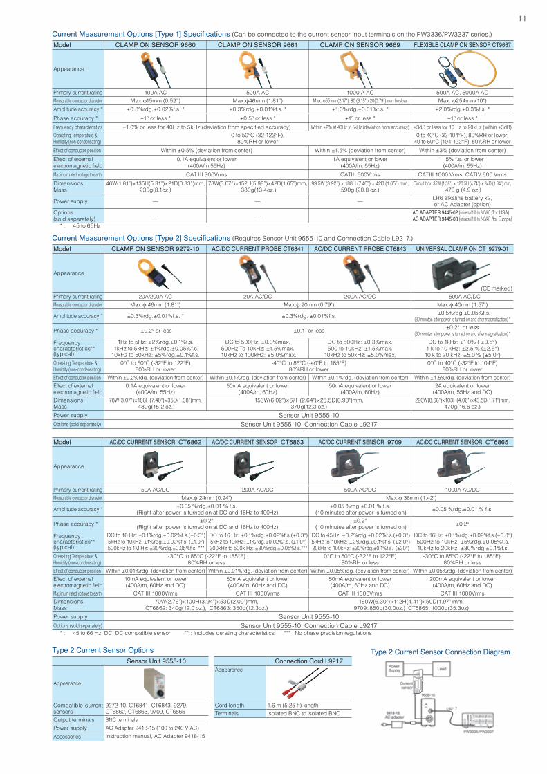
Type 2 Current Sensor OptionsSensor Unit 9555-10
Appearance
Compatible current sensors
9272-10, CT6841, CT6843, 9279, CT6862, CT6863, 9709, CT6865
Output terminals BNC terminalsPower supply AC Adapter 9418-15 (100 to 240 V AC)
Accessories Instruction manual, AC Adapter 9418-15
Type 2 Current Sensor Connection Diagram
Current Measurement Options [Type 1] Specifications (Can be connected to the current sensor input terminals on the PW3336/PW3337 series.)
Model CLAMP ON SENSOR 9660 CLAMP ON SENSOR 9661 CLAMP ON SENSOR 9669 FLEXIBLE CLAMP ON SENSOR CT9667
Appearance
Primary current rating 100A AC 500A AC 1000 A AC 500A AC, 5000A ACMeasurable conductor diameter Max.φ15mm(0.59”) Max.φ46mm(1.81”) Max. φ55 mm(2.17"), 80 (3.15")×20(0.79") mm busbar Max. φ254mm(10") Amplitude accuracy * ±0.3%rdg.±0.02%f.s. * ±0.3%rdg.±0.01%f.s. * ±1.0%rdg.±0.01%f.s. * ±2.0%rdg.±0.3%f.s. *
Phase accuracy * ±1° or less * ±0.5° or less * ±1° or less * ±1° or less *
Frequency characteristics ±1.0% or less for 40Hz to 5kHz (deviation from specified accuracy) Within ±2% at 40Hz to 5kHz (deviation from accuracy) ±3dB or less for 10 Hz to 20kHz (within ±3dB)Operating Temperature &Humidity (non-condensating)
0 to 50°C (32-122°F),80%RH or lower
0 to 40°C (32-104°F), 80%RH or lower,40 to 50°C (104-122°F), 50%RH or lower
Effect of conductor position Within ±0.5% (deviation from center) Within ±1.5% (deviation from center) Within ±3% (deviation from center)
Effect of externalelectromagneticfield
0.1A equivalent or lower(400A/m,55Hz)
1A equivalent or lower(400A/m, 55Hz)
1.5% f.s. or lower(400A/m, 55Hz)
Maximum rated voltage to earth CAT III 300Vrms CATIII 600Vrms CATIII 1000 Vrms, CATIV 600 Vrms
Dimensions,Mass
46W(1.81”)×135H(5.31”)×21D(0.83”)mm,230g(8.1oz.)
78W(3.07”)×152H(5.98”)×42D(1.65”)mm, 380g(13.4oz.)
99.5W(3.92”)×188H(7.40”)×42D(1.65”)mm,590g (20.8 oz.)
Circuitbox:35W(1.38”)×120.5H(4.74”)×34D(1.34”)mm, 470 g (4.9 oz.)
Power supply — — — LR6 alkaline battery x2,or AC Adapter (option)
Options(sold separately) — — — AC ADAPTER 9445-02 (universal 100 to 240VAC /for USA)
AC ADAPTER 9445-03 (universal 100 to 240VAC /for Europe) * : 45 to 66Hz
Current Measurement Options [Type 2] Specifications (Requires Sensor Unit 9555-10 and Connection Cable L9217.)
Model CLAMP ON SENSOR 9272-10 AC/DC CURRENT PROBE CT6841 AC/DC CURRENT PROBE CT6843 UNIVERSAL CLAMP ON CT 9279-01
Appearance
(CE marked)Primary current rating 20A/200A AC 20A AC/DC 200A AC/DC 500A AC/DCMeasurable conductor diameter Max.φ 46mm (1.81") Max.φ 20mm (0.79") Max.φ 40mm (1.57")
Amplitude accuracy * ±0.3%rdg.±0.01%f.s. * ±0.3%rdg. ±0.01%f.s. ±0.5%rdg.±0.05%f.s.(30 minutes after power is turned on and after magnetization) *
Phase accuracy * ±0.2° or less ±0.1˚orless ±0.2° or less(30 minutes after power is turned on and after magnetization) *
Frequencycharacteristics**(typical)
1Hz to 5Hz: ±2%rdg.±0.1%f.s. 1kHz to 5kHz: ±1%rdg.±0.05%f.s.
10kHz to 50kHz: ±5%rdg.±0.1%f.s.
DC to 500Hz: ±0.3%max.500Hz To 10kHz: ±1.5%max.
10kHz to 100kHz: ±5.0%max.
DC to 500Hz: ±0.3%max.500 to 10kHz: ±1.5%max.
10kHz to 50kHz: ±5.0%max.
DC to 1kHz: ±1.0% ( ±0.5°) 1 k to 10 kHz: ±2.5 % (±2.5°)
10 k to 20 kHz: ±5.0 % (±5.0°)Operating Temperature &Humidity (non-condensating)
0°C to 50°C (-32°F to 122°F)80%RH or lower
-40°C to 85°C (-40°F to 185°F)80%RH or lower
0°C to 40°C (-32°F to 104°F)80%RH or lower
Effect of conductor position Within ±0.2%rdg. (deviation from center) Within ±0.1%rdg. (deviation from center) Within ±0.1%rdg. (deviation from center) Within ±1.5%rdg. (deviation from center)Effect of externalelectromagneticfield
0.1A equivalent or lower(400A/m, 55Hz)
50mA equivalent or lower(400A/m, 60Hz)
50mA equivalent or lower(400A/m, 60Hz)
2A equivalent or lower(400A/m, 55Hz and DC)
Dimensions,Mass
78W(3.07")×188H(7.40")×35D(1.38")mm, 430g(15.2 oz.)
153W(6.02")×67H(2.64")×25.5D(0.98")mm,370g(12.3 oz.)
220W(8.66")×103H(4.06")×43.5D(1.71")mm,470g(16.6 oz.)
Power supply Sensor Unit 9555-10Options (sold separately) Sensor Unit 9555-10, Connection Cable L9217
Model AC/DC CURRENT SENSOR CT6862 AC/DC CURRENT SENSOR CT6863 AC/DC CURRENT SENSOR 9709 AC/DC CURRENT SENSOR CT6865
Appearance
Primary current rating 50A AC/DC 200A AC/DC 500A AC/DC 1000A AC/DCMeasurable conductor diameter Max.φ 24mm (0.94") Max.φ 36mm (1.42")
Amplitude accuracy * ±0.05 %rdg.±0.01 % f.s. (Right after power is turned on at DC and 16Hz to 400Hz)
±0.05 %rdg.±0.01 % f.s. (10 minutes after power is turned on) ±0.05 %rdg.±0.01 % f.s.
Phase accuracy * ±0.2° (Right after power is turned on at DC and 16Hz to 400Hz)
±0.2° (10 minutes after power is turned on) ±0.2°
Frequencycharacteristics**(typical)
DC to 16 Hz: ±0.1%rdg.±0.02%f.s.(±0.3°) 5kHz to 10kHz: ±1%rdg.±0.02%f.s. (±1.0°)500kHz to 1M Hz: ±30%rdg.±0.05%f.s. ***
DC to 16 Hz: ±0.1%rdg.±0.02%f.s.(±0.3°) 5kHz to 10kHz: ±1%rdg.±0.02%f.s. (±1.0°)300kHz to 500k Hz: ±30%rdg.±0.05%f.s.***
DC to 45Hz: ±0.2%rdg.±0.02%f.s.(±0.3°) 5kHz to 10kHz: ±2%rdg.±0.1%f.s. (±2.0°)20kHz to 100kHz: ±30%rdg.±0.1%f.s. (±30°)
DC to 16Hz: ±0.1%rdg.±0.02%f.s.(±0.3°) 500Hz to 10kHz: ±5%rdg.±0.05%f.s. 10kHz to 20kHz: ±30%rdg.±0.1%f.s.
Operating Temperature &Humidity (non-condensating)
-30°C to 85°C (-22°F to 185°F)80%RH or less
0°C to 50°C (-32°F to 122°F)80%RH or less
-30°C to 85°C (-22°F to 185°F), 80%RH or less
Effect of conductor position Within ±0.01%rdg. (deviation from center) Within ±0.01%rdg. (deviation from center) Within ±0.05%rdg. (deviation from center) Within ±0.05%rdg. (deviation from center)Effect of externalelectromagneticfield
10mA equivalent or lower(400A/m, 60Hz and DC)
50mA equivalent or lower(400A/m, 60Hz and DC)
50mA equivalent or lower(400A/m, 60Hz and DC)
200mA equivalent or lower(400A/m, 60Hz and DC)
Maximum rated voltage to earth CAT III 1000Vrms CAT III 1000Vrms CAT III 1000Vrms CAT III 1000VrmsDimensions,Mass
70W(2.76")×100H(3.94")×53D(2.09")mm, CT6862: 340g(12.0 oz.), CT6863: 350g(12.3oz.)
160W(6.30")×112H(4.41")×50D(1.97")mm, 9709: 850g(30.0oz.) CT6865: 1000g(35.3oz)
Power supply Sensor Unit 9555-10Options (sold separately) Sensor Unit 9555-10, Connection Cable L9217 * : 45 to 66 Hz, DC: DC compatible sensor ** : Includes derating characteristics *** : No phase precision regulations
Connection Cord L9217
Appearance
Cord length 1.6 m (5.25 ft) lengthTerminals Isolated BNC to isolated BNC
HEADQUARTERS 81 Koizumi, Ueda, Nagano, 386-1192, Japan TEL +81-268-28-0562 FAX +81-268-28-0568 http://www.hioki.com / E-mail: [email protected]
HIOKI USA CORPORATION TEL +1-609-409-9109 FAX +1-609-409-9108 http://www.hiokiusa.com / E-mail: [email protected]
All information correct as of June 30, 2015. All specifications are subject to change without notice. PW3337E5-56E Printed in Japan
DISTRIBUTED BYHIOKI (Shanghai) SALES & TRADING CO., LTD. TEL +86-21-63910090 FAX +86-21-63910360 http://www.hioki.cn / E-mail: [email protected]
HIOKI INDIA PRIVATE LIMITED TEL +91-124-6590210 E-mail: [email protected]
HIOKI SINGAPORE PTE. LTD. TEL +65-6634-7677 FAX +65-6634-7477 E-mail: [email protected]
HIOKI KOREA CO., LTD. TEL +82-2-2183-8847 FAX +82-2-2183-3360 E-mail: [email protected]
Note: Company names and Product names appearing in this catalog are trademarks or registered trademarks of various companies.
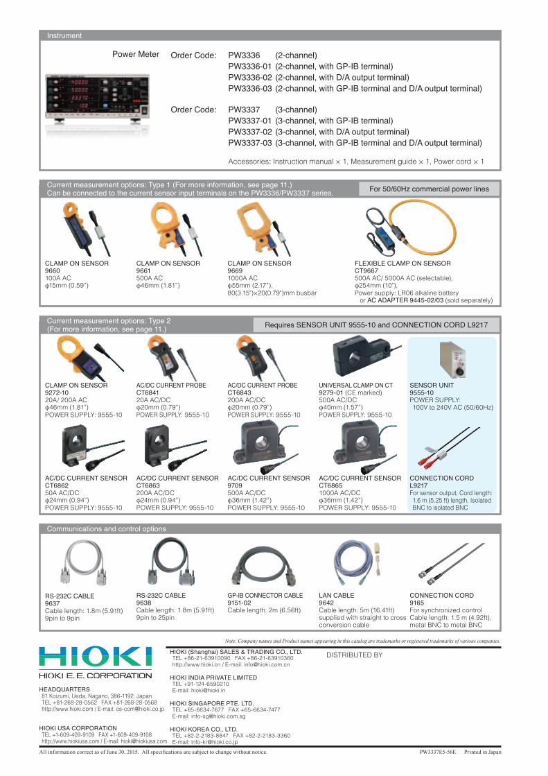
Instrument
Order Code: PW3336 (2-channel) PW3336-01 (2-channel, with GP-IB terminal) PW3336-02 (2-channel, with D/A output terminal) PW3336-03 (2-channel, with GP-IB terminal and D/A output terminal)
Order Code: PW3337 (3-channel) PW3337-01 (3-channel, with GP-IB terminal) PW3337-02 (3-channel, with D/A output terminal) PW3337-03 (3-channel, with GP-IB terminal and D/A output terminal)
Accessories: Instruction manual × 1, Measurement guide × 1, Power cord × 1
Communications and control options
RS-232C CABLE9637Cable length: 1.8m (5.91ft)9pin to 9pin
RS-232C CABLE9638Cable length: 1.8m (5.91ft)9pin to 25pin
GP-IB CONNECTOR CABLE9151-02Cable length: 2m (6.56ft)
LAN CABLE9642Cable length: 5m (16.41ft)supplied with straight to cross conversion cable
CONNECTION CORD9165For synchronized controlCable length: 1.5 m (4.92ft),metal BNC to metal BNC
Current measurement options: Type 2 (For more information, see page 11.) Requires SENSOR UNIT 9555-10 and CONNECTION CORD L9217
CLAMP ON SENSOR9272-1020A/ 200A ACφ46mm(1.81”)POWER SUPPLY: 9555-10
AC/DC CURRENT SENSORCT686250A AC/DCφ24mm(0.94”)POWER SUPPLY: 9555-10
AC/DC CURRENT SENSORCT6863200A AC/DCφ24mm(0.94”)POWER SUPPLY: 9555-10
AC/DC CURRENT SENSOR9709500A AC/DCφ36mm(1.42”)POWER SUPPLY: 9555-10
AC/DC CURRENT SENSORCT68651000A AC/DCφ36mm(1.42”)POWER SUPPLY: 9555-10
AC/DC CURRENT PROBECT684120A AC/DCφ20mm(0.79”)POWER SUPPLY: 9555-10
AC/DC CURRENT PROBECT6843200A AC/DCφ20mm(0.79”)POWER SUPPLY: 9555-10
UNIVERSAL CLAMP ON CT9279-01 (CE marked)500A AC/DCφ40mm(1.57”)POWER SUPPLY: 9555-10
SENSOR UNIT9555-10POWER SUPPLY: 100V to 240V AC (50/60Hz)
CONNECTION CORDL9217For sensor output, Cord length: 1.6 m (5.25 ft) length, Isolated BNC to isolated BNC
Current measurement options: Type 1 (For more information, see page 11.) Can be connected to the current sensor input terminals on the PW3336/PW3337 series.
CLAMP ON SENSOR96691000A ACφ55mm(2.17”),80(3.15")×20(0.79")mm busbar
CLAMP ON SENSOR9661500A ACφ46mm(1.81”)
FLEXIBLE CLAMP ON SENSORCT9667500A AC/ 5000A AC (selectable),φ254mm (10"),Power supply: LR06 alkaline battery or AC ADAPTER 9445-02/03 (sold separately)
CLAMP ON SENSOR9660100A ACφ15mm(0.59”)
For 50/60Hz commercial power lines
Power Meter