possible mechanism for observed dynamic resistance
TRANSCRIPT
408 IEEE TRANSACTIONS ON COMPONENTS AND PACKAGING TECHNOLOGIES, VOL. 24, NO. 3, SEPTEMBER 2001
Possible Mechanism for ObservedDynamic Resistance
Robert D. Malucci, Member, IEEE
Abstract—A possible mechanism was proposed to explain theobservance of motion induced short-term electrical discontinuitiesin degraded tin plated contacts (nanosecond). This mechanismrequires unique conditions where cold-welded wear particlesare stretched and sheared to the fracture limit during sliding. Itis speculated that the release of elastic energy during fracturepropagates through the surface structure at the speed of soundand causes rapid changes in contact resistance. An analysis ofthe microstructure was conducted and indicates this mechanismis theoretically possible. Moreover, data are provided that showincremental changes in normal force can cause counter intuitivechanges in resistance. This data shows large changes occur duringloading and unloading and it’s believed these changes are theresult of micro rocking that’s induced by the step loading system.It is estimated the distances covered by rocking range from a fewto tens of microns and the large changes in resistance are thoughtto result from making and breaking cold-welded asperities.In addition, this data suggests that a static contact resistancethreshold for discontinuities exist around the 100 m level. Thisis in agreement with other authors and lends credibility to the useof static contact resistance as a measure of contact stability.
Index Terms—Cold-welded asperities, discontinuities, tin platedcontacts.
I. INTRODUCTION
T HE performance of electrical contacts in connectorapplications is dependent on the mechanical and electrical
stability of the contact interface. Mechanical stability providesa stationary interface that performs as a static contact system.However, if the contact members degrade due to corrosion, ox-idation, or contamination, and relative motion occurs, electricalinstability can occur. This may impact system performance asa result of time-based discontinuities; where a momentary highresistance or open circuit causes data transmission errors insignal applications.
Several authors [1]–[3] have studied this type of phenomena.Abbott [1] found when the contact resistance distribution ex-hibits changes approaching a median value of 10 mthat avariety of contact materials exhibit a tendency to produce mo-tion induced short duration discontinuities ( ns). While thisdata does not discriminate between the different length discon-tinuities, it does appear to define a threshold for instability. Inaddition, Abbottet al. [2] found in a series of experiments ontin plated contacts, that different thresholds existed for a series
Manuscript received September 1, 2000; revised May 30, 2001. This workwas recommended for publication by Associate Editor J. W. McBride upon eval-uation of the reviewers’ comments.
The author is with Molex Incorporated, Lisle, IL 60532 USA (e-mail:[email protected]).
Publisher Item Identifier S 1521-3331(01)07551-1.
of time duration’s ranging from 20 to 1000 ns. The thresholdsappear to relate change in resistance to length of discontinuity,where greater changes in resistance produce greater lengths ofdiscontinuity. On the other hand, as provided in [2], the thresh-olds for specific cases ranging from 40 to 500 ns appear verysimilar (plots 2, 3, and 4 of [2]). It appears from this data thatthreshold behavior can be associated with static resistance dis-tributions, which typically have a median change in resistanceof about 10 m and a range up to about 100 m.
Murrell and McCarthy [3] using fretting motion to producedegradation performed similar experiments. These researchersalso found motion-induced discontinuities (for tin plated con-tacts) ranging from tens of ns to ms. However, Murrell and Mc-Carthy point out that it is difficult to explain the shortest dis-continuities (in terms of the asperity model) as the interfacedoes not experience sufficient relative motion to cause resis-tance changes. They hypothesize that a granular structure wheretunneling plays a role in the conduction mechanism, may ex-plain the short discontinuities (20 to 2000 ns). However, theydon’t provide any analysis to support this hypothesis. More-over, Murrell and McCarthy’s data show that short discontinu-ities do not occur in unplated copper contacts and are very rarein tin contacts, whereas long discontinuities ( ms) occur atsignificantly higher rates. In addition, as seen in Figs. 6 and 7of Murrell and McCarthy’s paper [3], discontinuities appear tooccur when the level of degradation in contact resistance reacheschanges up to about 100 m. These results indicate that in thetin case one sees long discontinuities more often and earlier thanshort discontinuities. If this is true for all cases, then one mayconclude that the importance of short discontinuities on systemperformance is minimal.
In an effort to understand motion-induced discontinuities (atthe tens of ns level) this author conducted a series of fretting testsin a previous study [4]. The results showed that the develop-ment of oxide films due to fretting corrosion saturate in oxygencontent. It was found, after 1000 fretting cycles, the film sat-urates below the percolation limit of metal volume content formetallic conductivity ( ). It was also observed that a rela-tively small movement could cause very large changes in contactresistance. For example, it was found that the resistance couldchange from around 0.1 to several ohms with about a 10-mwipe. In addition, the conduction medium had resistivities ata level expected for semiconductors. Consequently it was con-cluded that the conduction medium was principally due to thesemiconductor properties of the tin/tin oxide mixture where tun-neling between grains probably occurs. (However, this was notverified by measuring resistivity as a function of temperature.)Moreover, the microstructure observed had several interesting
1521–3331/01$10.00 ©2001 IEEE
MALUCCI: POSSIBLE MECHANISM FOR OBSERVED DYNAMIC RESISTANCE 409
features such as particulate matter with metal volume fractionsnear or above the percolation limit. The latter of which may playa role in motion induced rapid changes in resistance. The pur-pose of this paper is to provide an analysis of these data and de-termine how this type of phenomena is possible with the struc-tures and characteristics observed in the detailed microstructureanalysis provided in [4].
II. A NALYSIS
One of the comments made in [3] was how very little move-ment occurs during the short-term discontinuities. In fact, basedon the sliding velocity of the probe, the relative motion at theinterface during the 20–40 ns discontinuities is less than anangstrom. It is difficult to believe this small movement, whichis less than the size of an atom, causes a rapid change in con-tact resistance (on the order of 10). Moreover, if tunnelingplays a role in these phenomena, then one would expect move-ments on the order of tens of angstroms as necessary to causeorders of magnitude change in conductivity as seen in variouspublished data [5], [6]. Based on this, one may conclude thatdiscontinuities less than 1 microsecond cannot occur due to rel-ative motion at the interface. Some other mechanism must bepresent that causes a rapid change in conductivity.
In thinking about this problem, one may speculate that a pos-sible mechanism is the fracture of cold-welds at the asperitylevel. This might cause a rapid change in resistance if the frac-ture destroys conductive paths that have metallic or near metallicconductivity. The fracture would propagate at the speed of soundand may cause a change in conductivity by orders of magnitude.This could happen in less than 10 ns as cold-welds are stretchedand sheared to the fracture point as the interface moves. Asthe cold-welds are plastically elongated and work hardened,they will reach a point where little or no movement is requiredfor the fracture to propagate. Subsequently, the fractured sur-face would tend to vibrate as elastically stored energy is re-leased. This would be analogous to stretching a rubber band tillit breaks. With little or no movement, rapid localized changesin the interface can occur due to this mechanism.
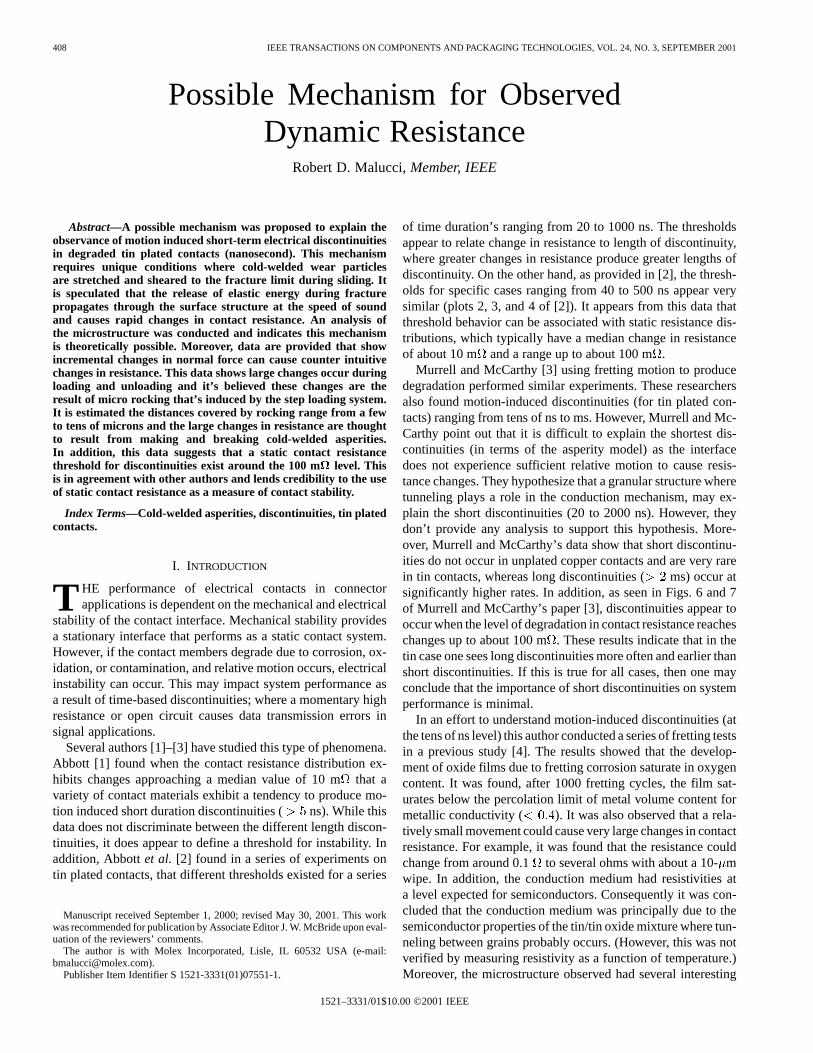
One might ask if the microstructure has features that cancause this mechanism to occur. The study in [4] showed frettingdegradation produces a complex mixture of tin and tin oxide inthe form of particulate matter imbedded in a continuous surface.The latter was also comprised of a tin and tin oxide mixture.Fig. 1(a)–(c) provide typical electron images of surface struc-tures found in the earlier study [4]. The volume fraction of metalto metal-oxide was found on a limited number of particles torange from about 0.4 to 0.8 where the majority of cases werearound 0.5. The fraction was lower in the compacted surface
.These structures have the potential to produce conditions at
the interface where particles of this type are trapped betweenthe contact members. In addition, due to the metal content, theseparticles are more conductive than the compact surface and mayprovide the principal current paths across the interface.
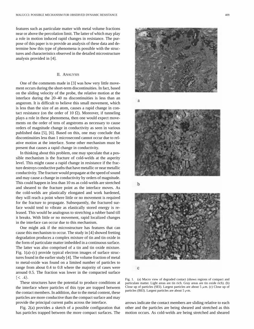
Fig. 2(a) provides a sketch of a possible configuration thathas particles trapped between the more compact surfaces. The
Fig. 1. (a) Macro view of degraded contact (shows regions of compact andparticulate matter. Light areas are tin rich. Gray areas are tin oxide rich). (b)Close up of particles (SEI). Largest particles are about 5�m. (c) Close up ofparticles (BEI). Largest particles are about 5�m.
arrows indicate the contact members are sliding relative to eachother and the particles are being sheared and stretched as thismotion occurs. As cold-welds are being stretched and sheared
410 IEEE TRANSACTIONS ON COMPONENTS AND PACKAGING TECHNOLOGIES, VOL. 24, NO. 3, SEPTEMBER 2001
Fig. 2. (a) Particles between sliding surfaces and (b) isolated particle beingstretched showing percolation path for currentI .
during this process, elastic energy is being stored in these struc-tures.
Fig. 2(b) shows an isolated particle that might be a low resis-tance tin path across the interface. This sketch is not intended toprovide an accurate scale of the particle structure but is shownas a qualitative representation of the complex tin and tin oxidemixture. The arrows represent the current path due to percola-tion through the tin part of the structure; the latter is assumedto be cold-welded at one or both ends. As the tin part of thestructure is stretched to its limit, it may fracture and produce amomentary loss of conductivity, which could cause a very rapidlarge change in contact resistance. If one assumes a particle sizeof 5 m it can be shown that as the path changes from perco-lation through the tin to conduction through the tin oxide, thebulk resistance of a particle can change from hundreds of mto as high as hundreds of. As one might imagine, there couldbe many particles of this composition interposed at the interface.The number would depend on the effective hardness of this com-position. All of these would have some statistical probability ofcold-welding, fracturing and providing a variable current pathwhen the structure releases elastic energy and vibrates. Conse-quently, under certain conditions these structures have the po-tential of producing rapid changes in contact resistance. Quan-titatively, one can see this by considering a number of particlesthat provide parallel current paths across the interface. In thiscase, the resistance consists of three resistive elements in series.Two are the oxidized compact layers. The third is the effectiveresistance of the particles. Since the change in resistance is as-
sumed to come from the parallel particle paths, one can considerwhat happens when one of the particles goes from a state of lowresistance to one of high resistance. The high resistance wouldoccur when a tin percolation path is broken. For the high resis-tance contribution, if one assumes for simplicityparticles ofequal size in parallel, the parallel resistance is calculated as fol-lows.
For the th particle the resistance is given as
(1)
where and are the resistivities of the compact layer andparticles respectively. The first two terms represent the constric-tion resistance from the ends of theth particle. The third term isthe bulk resistance for a particle of lengthand cross-sectionalarea of . For simplicity it will be assumed .Where is a shape factor and is expected to fall between 0 and1. This approximation will not change the order of magnitudeof the calculation. For particles in parallel, the conductivityis given as
(2)
From (2), for an average spot size of, the multi path resistancebecomes
(3)
where .If the same type of calculation is followed for the case where
one of the particles has become conductive due to percolationthrough a tin path, the parallel resistance becomes
(4)
where and is the resistivity of the tin path. Thedifference between (3) and (4) provide an estimate of the changethat can occur when one of the paths changes from conduc-tion through the tin/tin oxide mixture to percolation through acontinuous tin path. Consequently, the change in resistance be-comes
(5)
Combining (3)–(5) provide a quadratic equation foras afunction of as
(6)
where . The values for resistivity are givenas -cm for tin, and and
-cm for the tin/oxide mixture found for thesurface and particles respectively in [4]. In addition, for ,
and m, the value of is calculatedfrom (6). In addition, from (3) and (4) the parallel resistanceof the particle contributions are calculated asand respectively. So one can see that a change inresistance of 10 can occur if one of the paths changes fromsemi-conductor conditions to metallic percolation. Actually, the
MALUCCI: POSSIBLE MECHANISM FOR OBSERVED DYNAMIC RESISTANCE 411
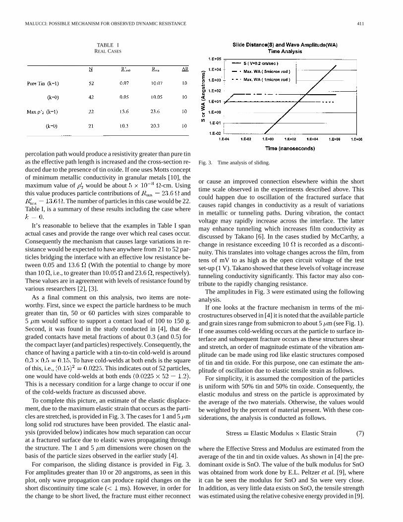
TABLE IREAL CASES
percolation path would produce a resistivity greater than pure tinas the effective path length is increased and the cross-section re-duced due to the presence of tin oxide. If one uses Motts conceptof minimum metallic conductivity in granular metals [10], themaximum value of would be about -cm. Usingthis value produces particle contributions of and
. The number of particles in this case would be 22.Table I, is a summary of these results including the case where
.It’s reasonable to believe that the examples in Table I span
actual cases and provide the range over which real cases occur.Consequently the mechanism that causes large variations in re-sistance would be expected to have anywhere from 21 to 52 par-ticles bridging the interface with an effective low resistance be-tween 0.05 and 13.6 (With the potential to change by morethan 10 , i.e., to greater than 10.05and 23.6 , respectively).These values are in agreement with levels of resistance found byvarious researchers [2], [3].
As a final comment on this analysis, two items are note-worthy. First, since we expect the particle hardness to be muchgreater than tin, 50 or 60 particles with sizes comparable to5 m would suffice to support a contact load of 100 to 150 g.Second, it was found in the study conducted in [4], that de-graded contacts have metal fractions of about 0.3 (and 0.5) forthe compact layer (and particles) respectively. Consequently, thechance of having a particle with a tin-to-tin cold-weld is around
. To have cold-welds at both ends is the squareof this, i.e., . This indicates out of 52 particles,one would have cold-welds at both ends .This is a necessary condition for a large change to occur if oneof the cold-welds fracture as discussed above.
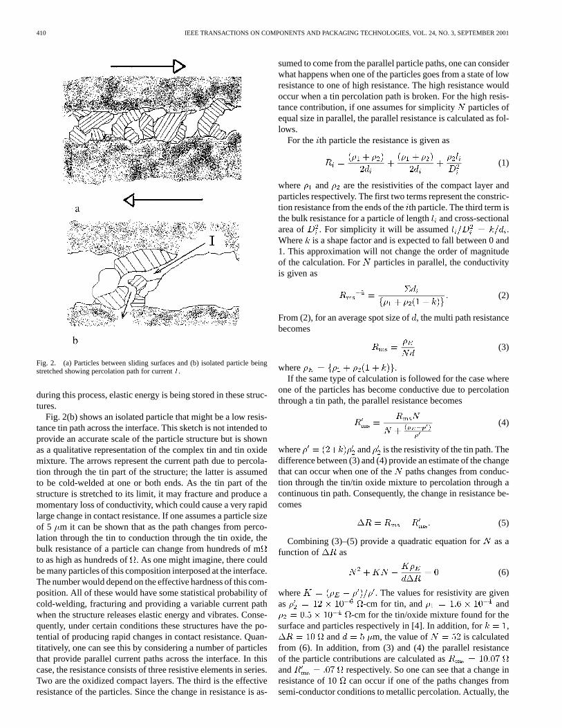
To complete this picture, an estimate of the elastic displace-ment, due to the maximum elastic strain that occurs as the parti-cles are stretched, is provided in Fig. 3. The cases for 1 and 5mlong solid rod structures have been provided. The elastic anal-ysis (provided below) indicates how much separation can occurat a fractured surface due to elastic waves propagating throughthe structure. The 1 and 5m dimensions were chosen on thebasis of the particle sizes observed in the earlier study [4].
For comparison, the sliding distance is provided in Fig. 3.For amplitudes greater than 10 or 20 angstroms, as seen in thisplot, only wave propagation can produce rapid changes on theshort discontinuity time scale ( ms). However, in order forthe change to be short lived, the fracture must either reconnect
Fig. 3. Time analysis of sliding.
or cause an improved connection elsewhere within the shorttime scale observed in the experiments described above. Thiscould happen due to oscillation of the fractured surface thatcauses rapid changes in conductivity as a result of variationsin metallic or tunneling paths. During vibration, the contactvoltage may rapidly increase across the interface. The lattermay enhance tunneling which increases film conductivity asdiscussed by Takano [6]. In the cases studied by McCarthy, achange in resistance exceeding 10is recorded as a disconti-nuity. This translates into voltage changes across the film, fromtens of mV to as high as the open circuit voltage of the testset-up (1 V). Takano showed that these levels of voltage increasetunneling conductivity significantly. This factor may also con-tribute to the rapidly changing resistance.
The amplitudes in Fig. 3 were estimated using the followinganalysis.
If one looks at the fracture mechanism in terms of the mi-crostructures observed in [4] it is noted that the available particleand grain sizes range from submicron to about 5m (see Fig. 1).If one assumes cold-welding occurs at the particle to surface in-terface and subsequent fracture occurs as these structures shearand stretch, an order of magnitude estimate of the vibration am-plitude can be made using rod like elastic structures composedof tin and tin oxide. For this purpose, one can estimate the am-plitude of oscillation due to elastic tensile strain as follows.
For simplicity, it is assumed the composition of the particlesis uniform with 50% tin and 50% tin oxide. Consequently, theelastic modulus and stress on the particle is approximated bythe average of the two materials. Otherwise, the values wouldbe weighted by the percent of material present. With these con-siderations, the analysis is conducted as follows.
Stress Elastic Modulus Elastic Strain (7)
where the Effective Stress and Modulus are estimated from theaverage of the tin and tin oxide values. As shown in [4] the pre-dominant oxide is SnO. The value of the bulk modulus for SnOwas obtained from work done by E.L. Peltzeret al. [9], whereit can be seen the modulus for SnO and Sn were very close.In addition, as very little data exists on SnO, the tensile strengthwas estimated using the relative cohesive energy provided in [9].
412 IEEE TRANSACTIONS ON COMPONENTS AND PACKAGING TECHNOLOGIES, VOL. 24, NO. 3, SEPTEMBER 2001
Using values for the tensile strength of tin and tin oxide (SnO)as 3.3 kg/mm and 4.9 kg/mm and the values for the moduliof 4240 kg/mm and 3728 kg/mm, respectively, the strain isestimated from (7) as
Elastic Strain
And since the Strain Change in Length/Rod Length, for arod of length 5 m (the maximum particle size), the change inlength is estimated as
Change in Length (8)
A similar analysis can be conducted for shear waves with theresult that the movement for a 5-m structure would be about110 . These values represent estimates of the largest wave am-plitudes that can occur for the microstructures seen in [4] in thecase where cold-welding occurs across the full cross section.If the tin oxide surface does not cold-weld, then the values de-crease to about 21 and 46for tensile and shear, respectively.For smaller structures and less cold-welding the values woulddecrease accordingly. Consequently, one would expect a spec-trum of values for a given set of interface conditions. It shouldbe noted that the calculated maximum elastic strain depends onthe accuracy of the modulus and strength of the SnO. Since thisdata is not readily found in the literature it’s difficult to deter-mine the reliability of the values obtained in [9]. Therefore, thevalues provided above should be viewed with some caution. Forexample, it may be that SnO is much harder than Sn. Conse-quently, one would expect the yield strength to be greater thanthe estimate made from the data in [9]. If we assume SnO is 5times stronger than the value used above, the change in lengthin (8) would be about 2.5 times greater. On the other hand ifit is assumed that only the tin is cold-welded, then the changein length is about 21 as discussed above. Evidently, the me-chanical properties of SnO have a significant impact on the casewhere cold-welding occurs across the tin and tin oxide surface.
In addition, one can estimate the distance these disturbancespropagate in short times (such as 20 ns). This is done using thelongitudinal and shear propagation velocities in an assumed tinand tin oxide mixture (i.e., m/s, m/s),[8]. These results indicate that longitudinal and shear waves inthe tin/tin oxide mixture can travel 55 and 34m, respectively.These distances are comparable to a sizable fraction of the con-tact region (the latter may have a radius of 200m). Whetheror not this happens may be debatable, as the microstructure dueto fretting degradation is a complex mixture of tin and tin oxideover nickel. A simple model such as this can only be consid-ered a rough order of magnitude approximation in cases wheresignificant degradation has occurred. It should be noted that thevelocity of sound varies significantly for the materials found inthis mixture and therefore wave propagation will be more com-plex than is assumed in this simple analysis. One would expectthat waves traveling in tin and tin oxide would be significantlyreflected when incident on the nickel surfaces. Consequently, asignificant amount of scattering will occur and the effects willtend to dampen the amplitude and dissipate the elastic energy.Further study of the effects of the composite structure require
a major effort and will not be addressed in detail in this paper.It is expected that damping will shorten the range and reducethe effect such waves have on nearby cold-welds. However, ifadditional cold-welds fracture as a result of the energy releasedfrom earlier fractures, additional elastic energy will be releasedto renew wave propagation. Although the present analysis issimplistic, it does lead to the conclusion that short-term discon-tinuities on the order of ns are theoretically possible.
If one follows this same line of thought for copper, it is foundthe change in length of a 5-m rod is about double the value fortin at 98 and the distance propagated in 20 ns would be about76 m.
What’s been shown in this analysis is that a cold-weld frac-ture mechanism at the asperity level has the potential of pro-ducing large short-term variations in resistance with little or nosliding movement at the contact interface. This is thought to bethe result of micro-oscillations at the asperity level that prop-agate at the speed of sound. This in turn can cause variation intunneling conductivity due to mechanical motion and associatedvariations in contact voltage. These phenomena may explain theobservance of very short discontinuities.
As a final note, Murrell and McCarthy found no short discon-tinuities in the case of copper, whereas this analysis indicatesit’s possible. However, it should be noted that the mechanismdescribed above depends on the statistical chance that a limitednumber of particles cold-weld, fracture and provide one or morelow resistance paths. Since copper is about ten times harder thantin there is less real contact area and consequently less chanceof cold-welding and the occurrence of fractures and reconnec-tion. This may explain the absence (or very low frequency) ofobserved short discontinuities in degraded copper interfaces.
III. D ISCUSSION
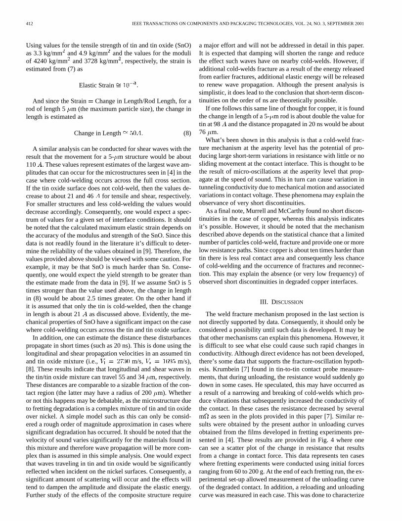
The weld fracture mechanism proposed in the last section isnot directly supported by data. Consequently, it should only beconsidered a possibility until such data is developed. It may bethat other mechanisms can explain this phenomena. However, itis difficult to see what else could cause such rapid changes inconductivity. Although direct evidence has not been developed,there’s some data that supports the fracture-oscillation hypoth-esis. Krumbein [7] found in tin-to-tin contact probe measure-ments, that during unloading, the resistance would suddenly godown in some cases. He speculated, this may have occurred asa result of a narrowing and breaking of cold-welds which pro-duce vibrations that subsequently increased the conductivity ofthe contact. In these cases the resistance decreased by severalm as seen in the plots provided in this paper [7]. Similar re-sults were obtained by the present author in unloading curvesobtained from the films developed in fretting experiments pre-sented in [4]. These results are provided in Fig. 4 where onecan see a scatter plot of the change in resistance that resultsfrom a change in contact force. This data represents ten caseswhere fretting experiments were conducted using initial forcesranging from 60 to 200 g. At the end of each fretting run, the ex-perimental set-up allowed measurement of the unloading curveof the degraded contact. In addition, a reloading and unloadingcurve was measured in each case. This was done to characterize
MALUCCI: POSSIBLE MECHANISM FOR OBSERVED DYNAMIC RESISTANCE 413
Fig. 4. Scatter plot of stability.
the electrical properties of the film that developed from frettingcorrosion. All of this data was used to make the plot in Fig. 4.
The data show four regions (quadrants) in the plot. The datain the upper left and lower right quadrants would be expected onan intuitive basis. In these cases, as expected, an increase or de-crease in force produces a decrease or increase in contact resis-tance respectively. On the other hand, the data seen in the upperright and lower left quadrants indicate counter-intuitive perfor-mance (where the resistance goes up and down as the force goesup and down respectively). The unloading data (lower left quad-rant) show similar characteristics compared to the Krumbein re-sults except the contact resistance is much greater as a result offretting degradation. In these results, changes in resistance onthe order of several ohms are observed. It is believed that themaking of cold-welds play a role in causing sudden large de-creases in resistance. This is thought to be the result of a rockingmotion produced by the loading system as discussed later in thissection. Although the examples given in the previous sectionmay be very rough approximations to actual cases, this analysisprovides a feasible basis to explain short-term discontinuities.
As discussed in the previous section, the picture provided isone where cold-welded asperities are stretched or sheared to thefracture point as relative motion of the interface occurs. Uponfracture, the freed surface rebounds and a wave front propagatesthrough the asperity structure until the wave is reflected from amore rigid boundary where it changes direction and moves to-ward the original or nearby positions. The incident wave couldimpact other cold-welds that are in some state of tensile andshear stress due to earlier surface movement. The stress level inthese cold-welds could increase beyond the fracture point andcause release of the elastic energy that was stored earlier in theweld structure. Theoretically, if the conditions were right, anavalanche of cold-weld fractures could occur. The effect is toprovide oscillating separations that can cause rapid variation inconductivity. This occurs when the separations disconnect andreconnect metallic (and tunneling) paths at the interface whilethe remaining paths conduct through semiconductor and tun-neling properties of the conduction medium. If the timing ofthese variations is just right, a short-term discontinuity couldoccur.
Fig. 5. Stability threshold.
One may note that relatively unique circumstances are neededfor this mechanism to work. First, at a given point in time,the interface should have cold-welded spots where one or morecold-welds have the potential of causing large changes in resis-tance when disconnected. This would happen if the welds essen-tially produced metallic (or near metallic) paths across the inter-face. Second, the structure of the cold-welded spots would haveto come from particulate matter or protrusions from the surface,as this would provide the size and free surface needed to oscil-late over tens of angstroms. In addition, the effective paths afterfracture may exhibit tunneling characteristics that depend on thevoltage across the path. While one may think the combination ofthese conditions seems unlikely, it should be noted that Murrelland McCarthy found the occurrence of short-term discontinu-ities much rarer than the longer-term cases (by at least two or-ders of magnitude). The present analysis would agree with thisobservation.
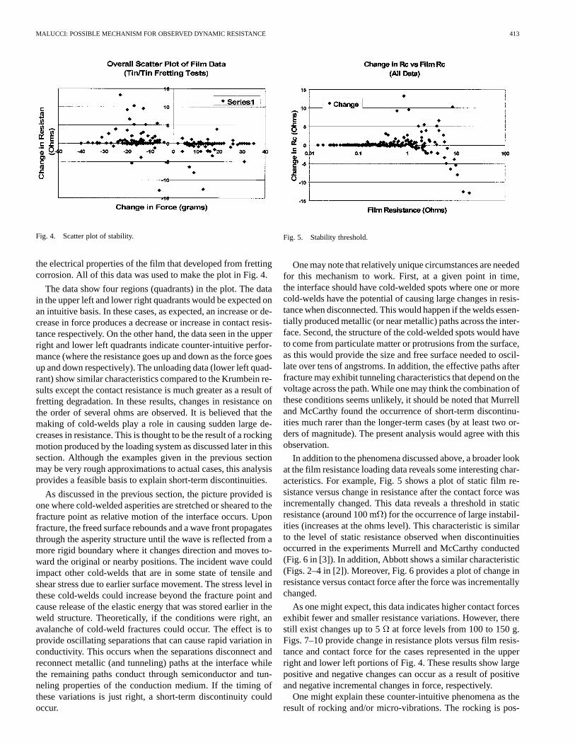
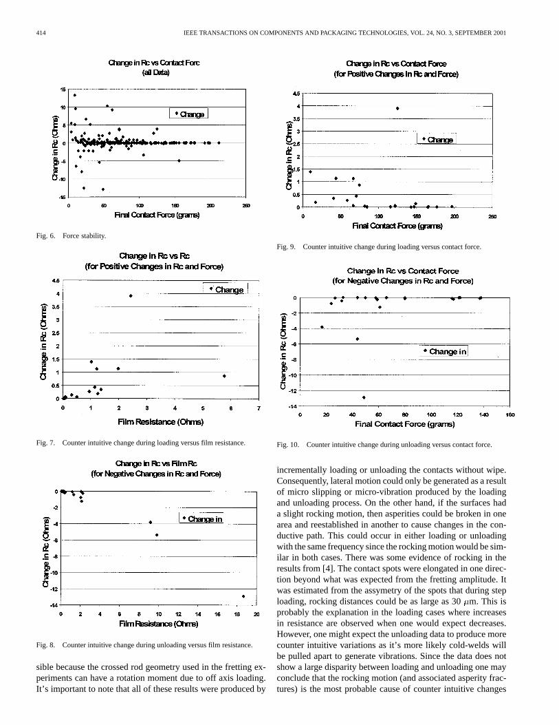
In addition to the phenomena discussed above, a broader lookat the film resistance loading data reveals some interesting char-acteristics. For example, Fig. 5 shows a plot of static film re-sistance versus change in resistance after the contact force wasincrementally changed. This data reveals a threshold in staticresistance (around 100 m) for the occurrence of large instabil-ities (increases at the ohms level). This characteristic is similarto the level of static resistance observed when discontinuitiesoccurred in the experiments Murrell and McCarthy conducted(Fig. 6 in [3]). In addition, Abbott shows a similar characteristic(Figs. 2–4 in [2]). Moreover, Fig. 6 provides a plot of change inresistance versus contact force after the force was incrementallychanged.
As one might expect, this data indicates higher contact forcesexhibit fewer and smaller resistance variations. However, therestill exist changes up to 5 at force levels from 100 to 150 g.Figs. 7–10 provide change in resistance plots versus film resis-tance and contact force for the cases represented in the upperright and lower left portions of Fig. 4. These results show largepositive and negative changes can occur as a result of positiveand negative incremental changes in force, respectively.
One might explain these counter-intuitive phenomena as theresult of rocking and/or micro-vibrations. The rocking is pos-
414 IEEE TRANSACTIONS ON COMPONENTS AND PACKAGING TECHNOLOGIES, VOL. 24, NO. 3, SEPTEMBER 2001
Fig. 6. Force stability.
Fig. 7. Counter intuitive change during loading versus film resistance.
Fig. 8. Counter intuitive change during unloading versus film resistance.
sible because the crossed rod geometry used in the fretting ex-periments can have a rotation moment due to off axis loading.It’s important to note that all of these results were produced by
Fig. 9. Counter intuitive change during loading versus contact force.
Fig. 10. Counter intuitive change during unloading versus contact force.
incrementally loading or unloading the contacts without wipe.Consequently, lateral motion could only be generated as a resultof micro slipping or micro-vibration produced by the loadingand unloading process. On the other hand, if the surfaces hada slight rocking motion, then asperities could be broken in onearea and reestablished in another to cause changes in the con-ductive path. This could occur in either loading or unloadingwith the same frequency since the rocking motion would be sim-ilar in both cases. There was some evidence of rocking in theresults from [4]. The contact spots were elongated in one direc-tion beyond what was expected from the fretting amplitude. Itwas estimated from the assymetry of the spots that during steploading, rocking distances could be as large as 30m. This isprobably the explanation in the loading cases where increasesin resistance are observed when one would expect decreases.However, one might expect the unloading data to produce morecounter intuitive variations as it’s more likely cold-welds willbe pulled apart to generate vibrations. Since the data does notshow a large disparity between loading and unloading one mayconclude that the rocking motion (and associated asperity frac-tures) is the most probable cause of counter intuitive changes
MALUCCI: POSSIBLE MECHANISM FOR OBSERVED DYNAMIC RESISTANCE 415
in resistance. However, there is no way to determine from thisdata if vibration plays a role in these changes, although it mostcertainly occurs at some level during the loading and unloadingprocess. These data serve to show the latter as being a reason-able possibility.
IV. CONCLUSION
A mechanism was proposed that has the potential of pro-ducing short-term discontinuities. It is based on the mechan-ical and elastic properties of the surface materials, where cold-welded asperities fracture and oscillate. As a result, it is be-lieved this type of mechanical disturbance can propagate alongthe interface and provide the opportunity for short-term eventsto occur. It was shown, that under unique conditions, the mi-crostructure of a degraded contact has the potential to causerapid changes in conductivity. The combined effects of thesephenomena create the possibility of producing short-term dis-continuities. While this scenario is probably rare in occurrence,it appears theoretically possible and may be the reason why suchevents are observed at low rates.
Moreover, as this model is not directly supported by data, itcan only be considered a reasonable speculation on how shortdiscontinuities occur. It is recommended that additional exper-iments be conducted to verify the existence (and frequency) ofshort-term events. It may be that in general these events are ex-tremely rare compared to longer discontinuities (as discussedearlier) and that studies of such phenomena are academic froma practical point of view.
In conclusion, while the proposed model is based on circum-stantial evidence, it does have the appealing feature of providinga feasible explanation of short-term discontinuities. The fact thatshort-term events are observed suggests this type of mechanismmay well be the cause. It may be that the specific details of thismechanism, as described in this paper, are incomplete, but somemechanism like this is needed to explain the short-term discon-tinuity phenomena.
ACKNOWLEDGMENT
The author would like to thank Dr. B. Rickett for useful dis-cussions and help in obtaining sources on material properties.
REFERENCES
[1] W. H. Abbott and K. L. Schreiber, “Dynamic constant resistance of gold,tin, and palladium connector interfaces during low amplitude motion,”in Proc. 27th Holm Conf. Electric Contacts, 1981, pp. 211–219.
[2] W. H. Abbott, “Time distribution of intermittents versus contact resis-tance for tin-tin connector interfaces during low amplitude motion,”IEEE Trans. Comp., Hybrids, Manufact. Technol., vol. CHMT-7, pp.107–111, Mar. 1984.
[3] S. R. Murrell and S. L. McCarthy, “Intermittence detection in frettingcorrosion studies of electrical contacts,” inProc. 43d IEEE Holm Conf.Elect. Contact, 1997, pp. 1–6.
[4] R. D. Malucci, “Characteristics of films developed in fretting experi-ments on tin plated contacts,” inProc. 45th, IEEE Holm Conf. Elect.Contacts, 1999, pp. 175–185.
[5] R. Holm, Electric Contacts. New York: Springer-Verlag, 1967, pp.123–128.
[6] E. Takamo, “Contact current distortion due to the tunnel effect,” inProc.45th, IEEE Holm Conf. Elect. Contacts, 1999, pp. 136–140.
[7] S. J. Krumbein, “Contact properties of tin-plates,”IEEE Trans. Parts,Hybrids, Packag., vol. PHP-11, June 1975.
[8] R. C. Weast,Handbook of Chemistry and Physics. Boca Raton, FL:CRC, 1985, p. E-43.
[9] E. L. Peltzer, “Calculated static and dynamic properties of�-Sn andSn–O compounds,”Phys. Rev. B, vol. 48, no. 21, Dec. 1993.
[10] N. F. Mott and E. A. Davis,Electronic Processes in Non-CrystallineMaterials. London, U.K.: Clarendon, p. 123.
Robert D. Malucci (M’90) received the B.S. and Ph.D. degrees in physics fromthe State University of New York at Buffalo.
He has worked in contact physics, applied research, and materials problemsassociated with the development of connectors during 22 of the last 28 years.He has had previous engagements at AMP and ITT in applied research, andFord Aerospace as a Technical Manager on air defense projects, including SDI.Currently, he is with Molex, Inc., as Director of the Reliability Group. His re-sponsibility encompasses product qualification, design development, materialsanalysis, and failure characterization.
Dr. Malucci is a member of ASM, APS, and IICIT. He has been active, for thelast 12 years, in helping organize and run the IEEE Holm Conference on elec-trical contacts and, as past Chairman, he is presently a member of the OperatingCommittee.