positron lifetime measurement device instruction … lifetime measurement device manual 5 technoap...
TRANSCRIPT
Positron lifetime measurement device
Instruction manual
Version 1.5
May, 2018
TechnoAP Co., Ltd.
ADD : 2976-15 Mawatari, Hitachinaka-shi, Ibaraki, Japan
ZIP Code: 312-0012
TEL: 029-350-8011
FAX: 029-352-9013
URL: http://www.techno-ap.com
e-mail: [email protected]

Positron lifetime measurement device manual
2 TechnoAP Co., Ltd.
- Contents
1. Safety Precautions / Disclaimer ............................................................................................................................... 3
2. Overview ..................................................................................................................................................................... 4
3. Setup ........................................................................................................................................................................... 5
3.1. Cable connection ....................................................................................................................................................... 5
3.2. Power on ..................................................................................................................................................................... 9
3.3. Installation of the application ..................................................................................................................................... 9
3.4. Setup of the network ............................................................................................................................................... 10
3.5. Start of the application ............................................................................................................................................. 11
4. Application screen ................................................................................................................................................... 12
4.1. Startup screen .......................................................................................................................................................... 12
4.2. Config tab .................................................................................................................................................................. 14
4.3. AMOC tab ................................................................................................................................................................. 15
4.4. CDB tab .................................................................................................................................................................... 17
4.5. lifetime tab ................................................................................................................................................................. 18
4.6. wave tab .................................................................................................................................................................... 20
4.7. energy tab ................................................................................................................................................................. 21
4.8. advanced tab ............................................................................................................................................................ 23
5. Measurement ........................................................................................................................................................... 31
5.1. Application of High voltage power supply ............................................................................................................... 31
5.2. energy mode ............................................................................................................................................................ 33
5.3. CDB mode ................................................................................................................................................................ 37
5.4. wave mode ............................................................................................................................................................... 41
5.5. lifetime mode ............................................................................................................................................................ 45
5.6. AMOC mode ............................................................................................................................................................ 49
6. File ............................................................................................................................................................................. 52
6.1. Configuration file ...................................................................................................................................................... 52
6.2. energy data file ......................................................................................................................................................... 54
6.3. lifetime data file ......................................................................................................................................................... 55
6.4. CDB data file ............................................................................................................................................................ 57
6.5. AMOC data file ......................................................................................................................................................... 58
6.6. wave data file ............................................................................................................................................................ 62
7. Troubleshooting ....................................................................................................................................................... 63
7.1. Communication error .............................................................................................................................................. 63
7.2. AMOC 3D graph problem ...................................................................................................................................... 64
8. Warranty policy ........................................................................................................................................................ 65

Positron lifetime measurement device manual
3 TechnoAP Co., Ltd.
1. Safety Precautions / Disclaimer
Thank you very much for purchasing the positron lifetime measurement device (hereinafter "This device") of TechnoAP
Co., Ltd. (hereinafter "We"). Please read this "Safety Precautions / Disclaimer" before using this device, be sure to
observe the contents, and use it correctly.
We are not responsible for any damage caused by abnormality of device, detector, connected device, application,
damage to failure, other secondary damage, even if accident caused by using this device.
Prohibited matter ⚫ This device cannot be used for applications requiring special quality and reliability
related to human life, accident. ⚫ This device cannot be used in places with high temperature, high humidity and
high vibration. ⚫ Do not apply strong shock or vibration to this device. ⚫ Do not disassemble or modify this device. ⚫ Do not wet this device with water or condensation. Do not operate this device
with wet hands. ⚫ If there is heat generation, deformation, discoloration, odor, etc. in this device,
stop using it immediately and contact us.
Notes
⚫ Use this device at room temperature in the operating temperature range and use it so that there is no condensation.
⚫ If there is smoking or abnormal heat generation in this device, turn off the power immediately.
⚫ Be careful of static electricity because this device is a precision electronic device. ⚫ Do not store this device in a dusty place or high temperature / high humidity
place. ⚫ Do not place devices that emit strong electromagnetic waves, such as mobile
phones and transceivers, close to this device. ⚫ This device may malfunction in environments with high electrical noise. ⚫ The specifications of this device and related documents may be subject to
change without prior notice.
Positron lifetime measurement device manual
4 TechnoAP Co., Ltd.
2. Overview
This device is the measuring system that had the gamma beam energy spectrum measurement, the CDB
(Coincidence Doppler Broadening) measurement, the PALS (Positron Annihilation lifetime Spectroscopy)
measurement, waveform of 3GSPS measurement, AMOC (Age-Momentum Correlation) measurement function.
This device is comprised of the following product mainly.
➢ DSP (Digital Signal Processing) for gamma ray spectrum measurement (Model: APV8002)
➢ Timespectrum meter (Model: APV8702) for the PALS (Positron Annihilation lifetime Spectroscopy) measurement
➢ High voltage power supply 4 Channel (Model: APV3304)
➢ Pre-amp power supply 4 Channel (Model: APV4004)
➢ VME powered crates 7 slot (Model: APV9007)
This unit is connected to a switching hub with a PC (hereinafter PC) and a LAN cable and operated with the supplied
application "Positron Annihilation" (hereafter this application). You use that application for parameter setting of each
module, reading of spectrum data, and analysis of data.
The lifetime data file is saved even in prn format (space delimited) which is easily readable by PALSfit 3
(http://palsfit.dk/) developed by DTM (Technical University of Denmark) in Denmark.
This manual describes the handling of this system.
* The contents of this manual are subject to change without notice.
Revision history
Date Version Comments
2017 March 1.0 First edition
2017 December 1.1 Update application software screen
2018 March 1.2 Update CDB mode item
2018 March 1.3 Modification of partial expression
2018 May 1.5 Review of all contents
Positron lifetime measurement device manual
5 TechnoAP Co., Ltd.
3. Setup
3.1. Cable connection
After confirming that all the devices connected to this equipment are in the OFF state, connect this equipment with
various cables to Germanium semiconductor detector, BaF2 scintillation detector, etc. Connection diagrams
corresponding to each measurement mode are shown. For details of each measurement mode, refer to "5.
Measurement" below.
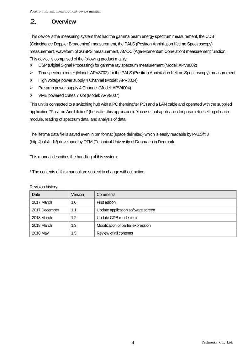
(1) wave mode, lifetime mode
VME Power SuppliesAPV9007
BaF2 #2 PMTBaF2 #1PMT
Start1.275 MeV
Sample
Stop511 keV
PC Time Spectrometer APV8702
Energy Spectrometer APV8002
Preamp Power APV4004
High Voltage APV3304
SwitchingHub
PositronAnnihilationApplication
CH3
CH4
CH1
CH2
Figure 1: Connection diagrams of wave mode and lifetime mode
➢ Connect high voltage power supply APV3304 and each detector with the cable (figure red) with the SHV
connector. In the standard specification, connect CH3 and CH4 of APV3304 to BaF2 scintillation detector.
*High voltage power supply CH1 and CH2 are the maximum rating for Germanium semiconductor
detector + (plus) 5,000V. Please be careful not to be connected to the BaF2 scintillation detector.
➢ Connect the time spectrometer APV8702 and the BaF2 scintillation detector with a cable with SMA
connector (green). If the detector side is a BNC connector, use the BNC-SMA conversion adapter. Connect
START detector to CH1 and STOP detector to CH2 of APV8702.
➢ Connect APV3304 and APV8702 and a PC to a switching hub with an LAN cable (black).
Positron lifetime measurement device manual
6 TechnoAP Co., Ltd.
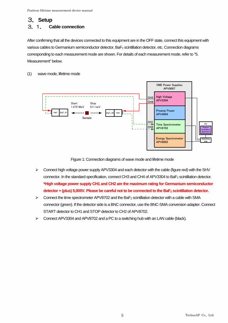
(2) CDB mode, energy mode
VME Power SuppliesAPV9007
PC
Ge #1Preamp
511keV 511keV
Ge #2 Preamp
Sample
Time Spectrometer APV8702
Energy Spectrometer APV8002
Preamp Power APV4004
High Voltage APV3304
SwitchingHub
PositronAnnihilationApplication
CH1
CH2
CH1CH2
CH1
CH2
Figure 2: Connection diagrams of CDB mode, energy mode
➢ Connect high voltage power supply APV3304 and each detector with the cable (figure red) with the SHV
connector. In the standard specification, connect CH1 and CH2 of APV3304 to Germanium semiconductor
detector.
*High voltage power supply CH3 and CH4 are the maximum rating for BaF2 scintillation detector
- (minus) 4,000V. Please be careful not to be connected to the Germanium semiconductor detector.
➢ Connect pre-amp power supply APV4004 and a Germanium semiconductor detector with the cable (figure
blue) with the standard 9-pin “D-type” (D-Sub 9-pin) connector.
➢ Connect DSP APV8002 and a Germanium semiconductor detector with the cable (orange) with the BNC
connector. CH1 and CH2 of APV8002 use BNC-LEMO conversion adapter for LEMO connector.
➢ Connect APV3304 and APV8002 and a PC to a switching hub with an LAN cable (black).

Positron lifetime measurement device manual
7 TechnoAP Co., Ltd.
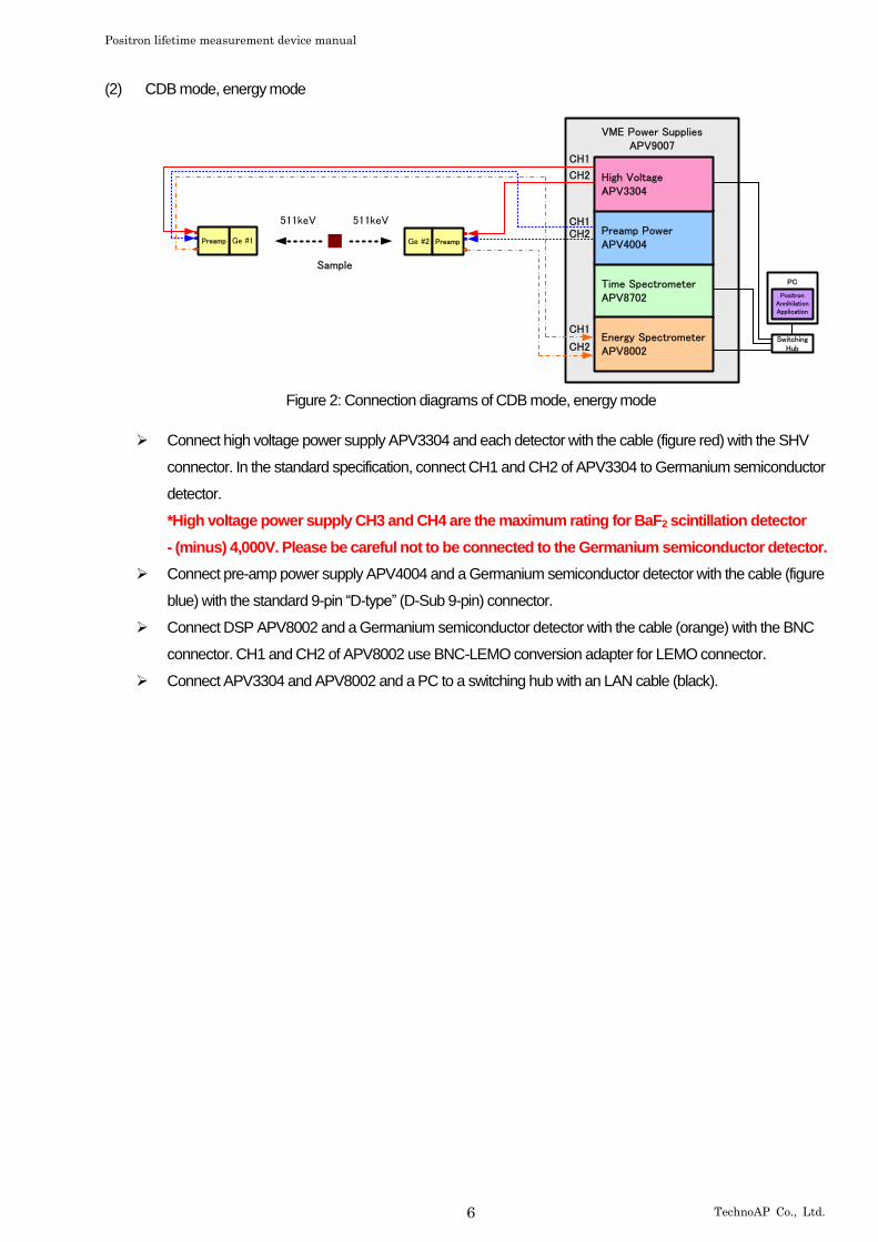
(3) AMOC mode
VME Power SuppliesAPV9007
BaF2 #2 PMT
BaF2 #1 PMT
Ge #1Preamp
Stop511keV
Stop511keV
Start1.275MeV
Sample
PC Time Spectrometer APV8702
Energy Spectrometer APV8002
Preamp Power APV4004
High Voltage APV3304
SwitchingHub
PositronAnnihilationApplication
CH1
CH3
CH1
CH1
CH4
CH1
CH2
Figure 3: Connection diagrams of AMOC mode
➢ Connect high voltage power supply APV3304 and each detector with the cable (figure red) with the SHV
connector. In the standard specification, connect Germanium semiconductor detector to CH1 and BaF2
scintillation detector to CH3 and CH4 of APV3304.
*High voltage power supply CH1 and CH2 are the maximum rating for Germanium semiconductor
detector + (plus) 5,000V. High voltage power supply CH3 and CH4 are the maximum rating for BaF2
scintillation detector - (minus) 4,000V. Please pay attention to cable connection.
➢ Connect pre-amp power supply APV4004 and a Germanium semiconductor detector with the cable (figure
blue) with the standard 9-pin “D-type” (D-Sub 9-pin) connector.
➢ Connect the time spectrometer APV8702 and the BaF2 scintillation detector with a cable with SMA
connector (green). If the detector side is a BNC connector, use the BNC-SMA conversion adapter. Connect
START detector to CH1 and STOP detector to CH2 of APV8702.
➢ Connect DSP APV8002 and a Germanium semiconductor detector with the cable (orange) with the BNC
connector. CH1 and CH2 of APV8002 use BNC-LEMO conversion adapter for LEMO connector.
➢ Connect APV3304 and APV8002 and a PC to a switching hub with an LAN cable (black).
Positron lifetime measurement device manual
8 TechnoAP Co., Ltd.
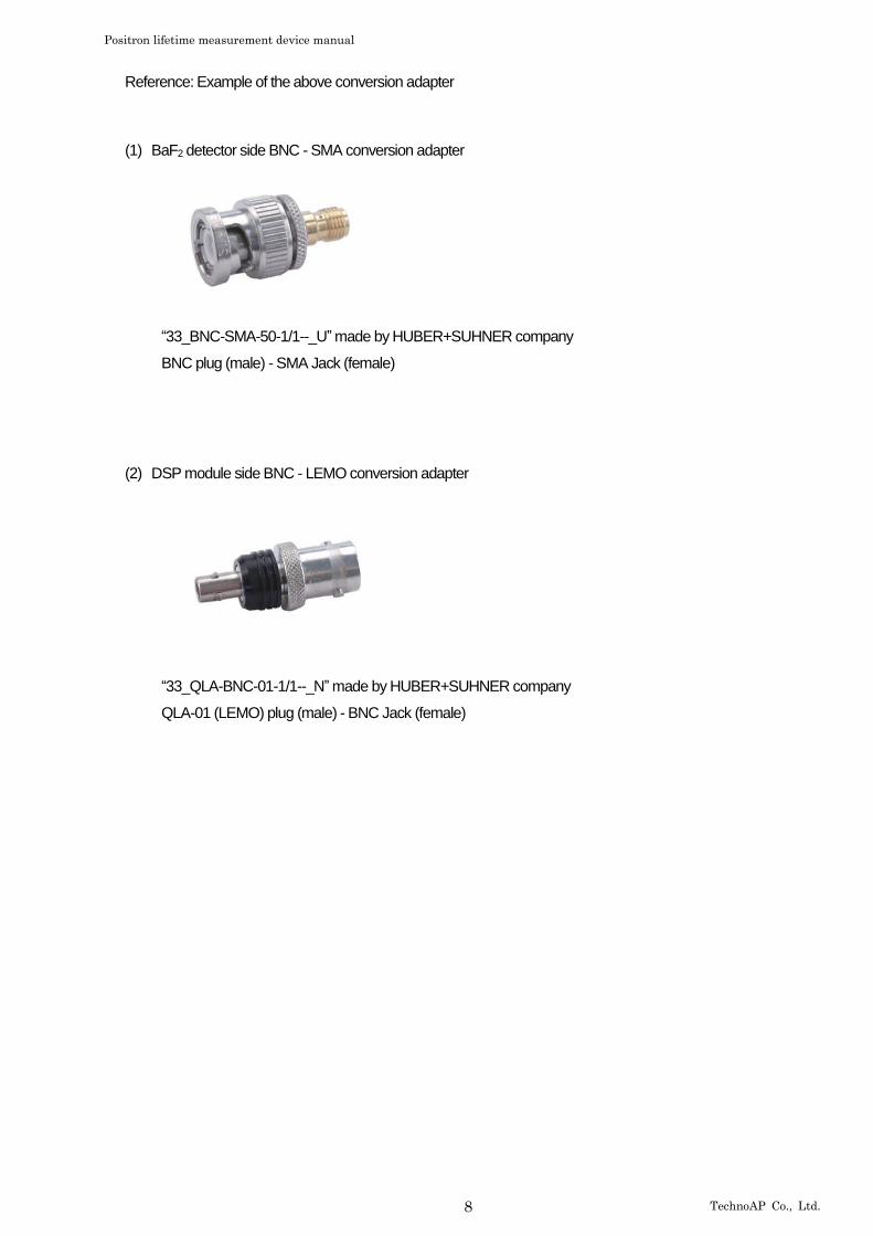
Reference: Example of the above conversion adapter
(1) BaF2 detector side BNC - SMA conversion adapter
“33_BNC-SMA-50-1/1--_U” made by HUBER+SUHNER company
BNC plug (male) - SMA Jack (female)
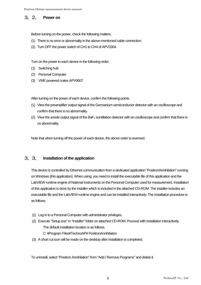
(2) DSP module side BNC - LEMO conversion adapter
“33_QLA-BNC-01-1/1--_N” made by HUBER+SUHNER company
QLA-01 (LEMO) plug (male) - BNC Jack (female)
Positron lifetime measurement device manual
9 TechnoAP Co., Ltd.
3.2. Power on
Before turning on the power, check the following matters.
(1) There is no error or abnormality in the above-mentioned cable connection.
(2) Turn OFF the power switch of CH1 to CH4 of APV3304.
Turn on the power to each device in the following order.
(1) Switching hub
(2) Personal Computer
(3) VME powered crates APV9007
After turning on the power of each device, confirm the following points.
(1) View the preamplifier output signal of the Germanium semiconductor detector with an oscilloscope and
confirm that there is no abnormality.
(2) View the anode output signal of the BaF2 scintillation detector with an oscilloscope and confirm that there is
no abnormality.
Note that when turning off the power of each device, the above order is reversed.
3.3. Installation of the application
This device is controlled by Ethernet communication from a dedicated application "PositronAnnihilation" running
on Windows (this application). When using, you need to install the executable file of this application and the
LabVIEW runtime engine of National Instruments on the Personal Computer used for measurement. Installation
of this application is done by the installer which is included in the attached CD-ROM. The installer includes an
executable file and the LabVIEW runtime engine and can be installed interactively. The installation procedure is
as follows.
(1) Log in to a Personal Computer with administrator privileges.
(2) Execute "Setup.exe" in "Installer" folder on attached CD-ROM. Proceed with installation interactively.
The default installation location is as follows.
C: ¥Program Files¥TechnoAP¥ PositronAnnihilation
(3) A short cut icon will be made on the desktop after installation is completed.
To uninstall, select "Positron Annihilation" from "Add / Remove Programs" and delete it.
Positron lifetime measurement device manual
10 TechnoAP Co., Ltd.
3.4. Setup of the network
Connect the Personal Computer and this device with network equipment such as LAN cable and switching hub. For the connection method, refer to the manual of each module (APV8002, APV8702, APV3304) which is a component of this equipment.
(1) Change the network information of the Personal Computer.
IP address 192.168.10.2 *It can be set arbitrarily. However, it sets a value which does not duplicate with the IP address described later
Subnet mask 255.255.255.0
Gateway (Default) 192.168.10.1
(2) Execute the ping command at the command prompt and check the connection between each module and the PC.
The IP address of each module is on the board. Please use wired LAN and disable wireless LAN when
not using wireless LAN. The default network information is as follows.
* Network information of APV8002
IP address 192.168.10.128 (Factory setting)
Subnet mask 255.255.255.0 (Factory setting)
Gateway (default) 192.168.10.1 (Factory setting)
* Network information of APV8702
IP address 192.168.10.129 (Factory setting)
Subnet mask 255.255.255.0 (Factory setting)
Gateway (default) 192.168.10.1 (Factory setting)
* Network information of APV3304
IP address 192.168.10.130 (Factory setting)
Subnet mask 255.255.255.0 (Factory setting)
Gateway (default) 192.168.10.1 (Factory setting)
Positron lifetime measurement device manual
11 TechnoAP Co., Ltd.
3.5. Start of the application
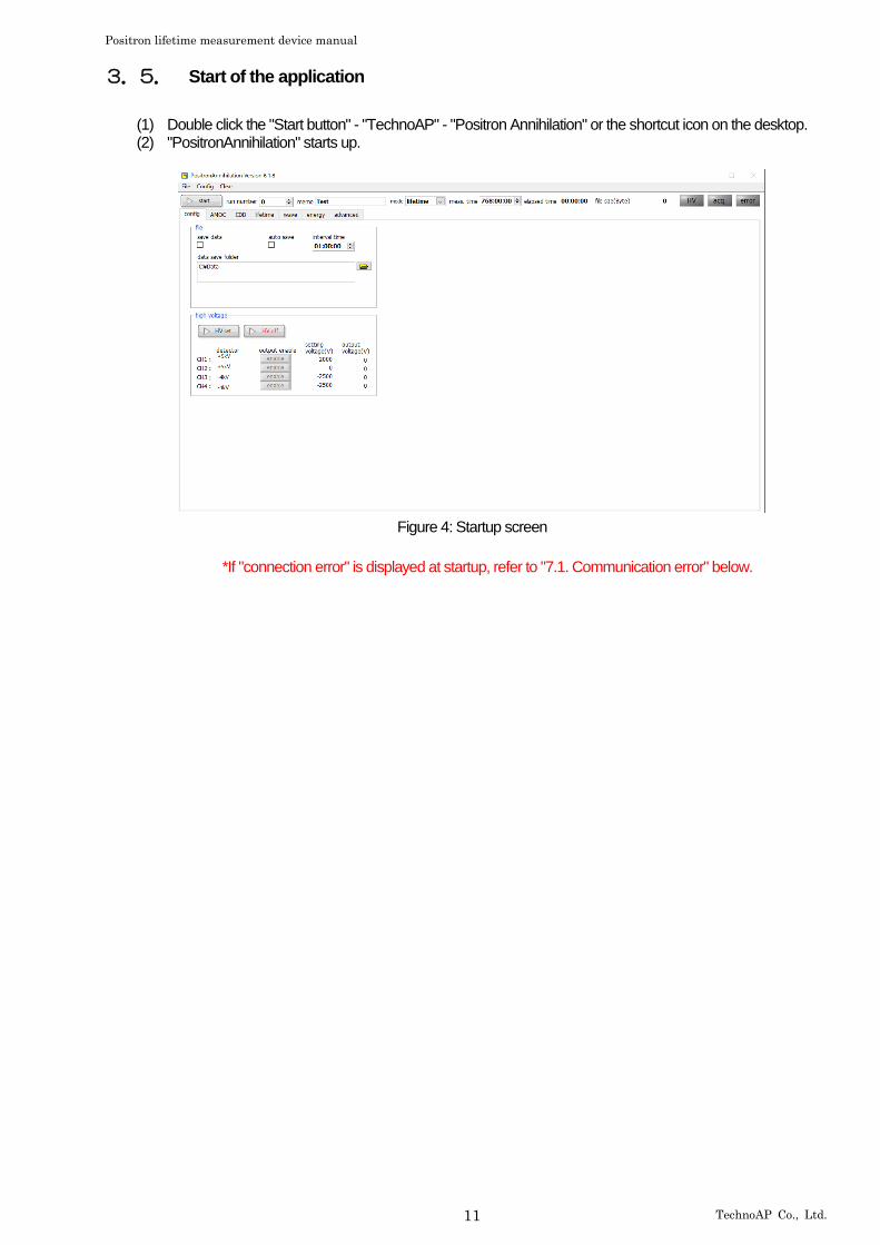
(1) Double click the "Start button" - "TechnoAP" - "Positron Annihilation" or the shortcut icon on the desktop. (2) "PositronAnnihilation" starts up.
Figure 4: Startup screen
*If "connection error" is displayed at startup, refer to "7.1. Communication error" below.

Positron lifetime measurement device manual
12 TechnoAP Co., Ltd.
4. Application screen
4.1. Startup screen
Figure 5: Startup screen
Menu
It consists of "File", "Config", "Clear".
"File" - "open config file" Load the configuration file.
"File" - "open AMOC file" Load the AMOC data file.
"File" - "open CDB file" Load the CDB data file.
"File" - "open lifetime file" Load the lifetime spectrum data file.
"File" - "open energy file" Load the energy spectrum data file.
"File" - "open list file" Load the list data file.
"File" - "save config file" Save current setting in a file.
"File" - "save AMOC file" Save the spectrum data which it acquired with AMOC mode.
"File" - "save CDB file" Save the lifetime spectrum data which it acquired with CDB mode.
"File" - "save lifetime file" Save the lifetime spectrum data which it acquired with lifetime mode.
"File" - "save wave file" Save the waveform data which it acquired with wave mode.
"File" - "save energy file" Save the waveform data which it acquired with wave mode.
"File" - "save image file" Save the capture image of the screen in PNG form file.
"File" - "reconnect HV device" Perform reconnect with high voltage power supply module.
"File" - "quit" Quit this application
Positron lifetime measurement device manual
13 TechnoAP Co., Ltd.
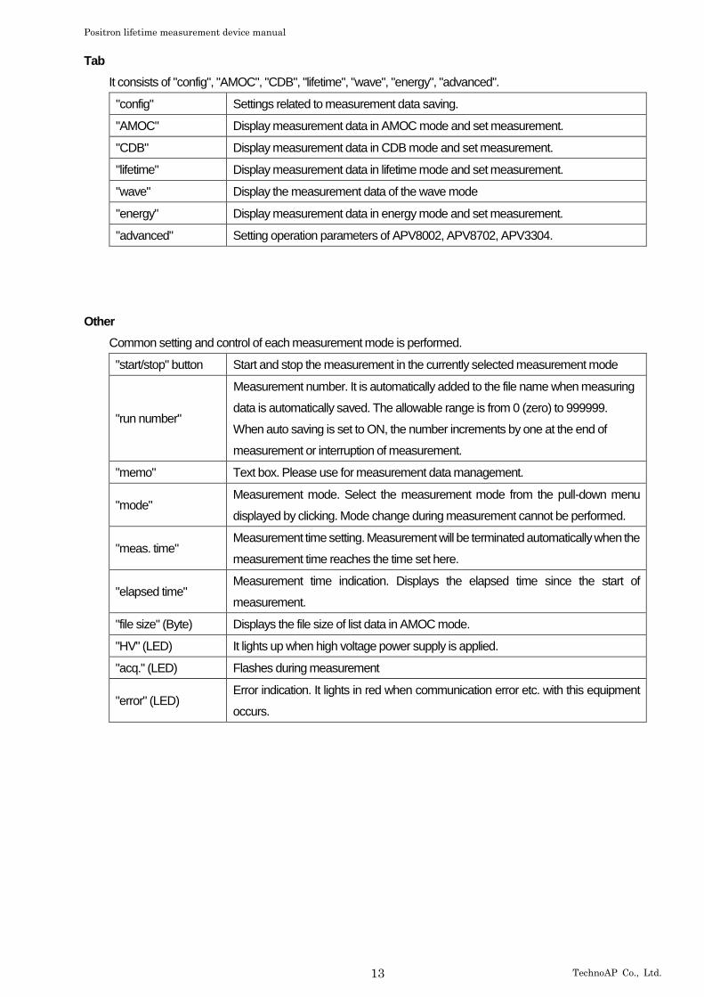
Tab
It consists of "config", "AMOC", "CDB", "lifetime", "wave", "energy", "advanced".
"config" Settings related to measurement data saving.
"AMOC" Display measurement data in AMOC mode and set measurement.
"CDB" Display measurement data in CDB mode and set measurement.
"lifetime" Display measurement data in lifetime mode and set measurement.
"wave" Display the measurement data of the wave mode
"energy" Display measurement data in energy mode and set measurement.
"advanced" Setting operation parameters of APV8002, APV8702, APV3304.
Other
Common setting and control of each measurement mode is performed.
"start/stop" button Start and stop the measurement in the currently selected measurement mode
"run number"
Measurement number. It is automatically added to the file name when measuring
data is automatically saved. The allowable range is from 0 (zero) to 999999.
When auto saving is set to ON, the number increments by one at the end of
measurement or interruption of measurement.
"memo" Text box. Please use for measurement data management.
"mode" Measurement mode. Select the measurement mode from the pull-down menu
displayed by clicking. Mode change during measurement cannot be performed.
"meas. time" Measurement time setting. Measurement will be terminated automatically when the
measurement time reaches the time set here.
"elapsed time" Measurement time indication. Displays the elapsed time since the start of
measurement.
"file size" (Byte) Displays the file size of list data in AMOC mode.
"HV" (LED) It lights up when high voltage power supply is applied.
"acq." (LED) Flashes during measurement
"error" (LED) Error indication. It lights in red when communication error etc. with this equipment
occurs.
Positron lifetime measurement device manual
14 TechnoAP Co., Ltd.
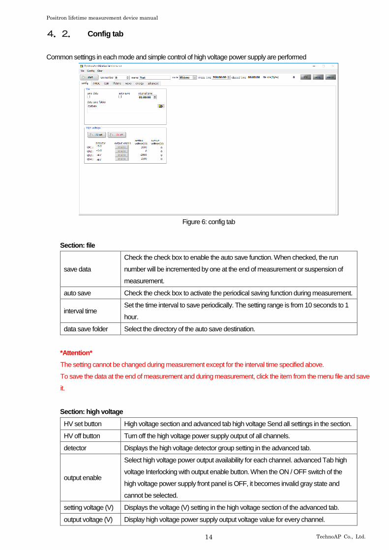
4.2. Config tab
Common settings in each mode and simple control of high voltage power supply are performed
Figure 6: config tab
Section: file
save data
Check the check box to enable the auto save function. When checked, the run
number will be incremented by one at the end of measurement or suspension of
measurement.
auto save Check the check box to activate the periodical saving function during measurement.
interval time Set the time interval to save periodically. The setting range is from 10 seconds to 1
hour.
data save folder Select the directory of the auto save destination.
*Attention*
The setting cannot be changed during measurement except for the interval time specified above.
To save the data at the end of measurement and during measurement, click the item from the menu file and save
it.
Section: high voltage
HV set button High voltage section and advanced tab high voltage Send all settings in the section.
HV off button Turn off the high voltage power supply output of all channels.
detector Displays the high voltage detector group setting in the advanced tab.
output enable
Select high voltage power output availability for each channel. advanced Tab high
voltage Interlocking with output enable button. When the ON / OFF switch of the
high voltage power supply front panel is OFF, it becomes invalid gray state and
cannot be selected.
setting voltage (V) Displays the voltage (V) setting in the high voltage section of the advanced tab.
output voltage (V) Display high voltage power supply output voltage value for every channel.
Positron lifetime measurement device manual
15 TechnoAP Co., Ltd.
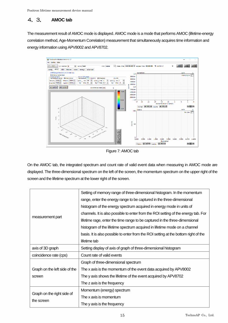
4.3. AMOC tab
The measurement result of AMOC mode is displayed. AMOC mode is a mode that performs AMOC (lifetime-energy
correlation method, Age-Momentum Correlation) measurement that simultaneously acquires time information and
energy information using APV8002 and APV8702.
Figure 7: AMOC tab
On the AMOC tab, the integrated spectrum and count rate of valid event data when measuring in AMOC mode are
displayed. The three-dimensional spectrum on the left of the screen, the momentum spectrum on the upper right of the
screen and the lifetime spectrum at the lower right of the screen.
measurement part
Setting of memory range of three-dimensional histogram. In the momentum
range, enter the energy range to be captured in the three-dimensional
histogram of the energy spectrum acquired in energy mode in units of
channels. It is also possible to enter from the ROI setting of the energy tab. For
lifetime rage, enter the time range to be captured in the three-dimensional
histogram of the lifetime spectrum acquired in lifetime mode on a channel
basis. It is also possible to enter from the ROI setting at the bottom right of the
lifetime tab
axis of 3D graph Setting display of axis of graph of three-dimensional histogram
coincidence rate (cps) Count rate of valid events
Graph on the left side of the
screen
Graph of three-dimensional spectrum
The x axis is the momentum of the event data acquired by APV8002
The y axis shows the lifetime of the event acquired by APV8702
The z axis is the frequency
Graph on the right side of
the screen
Momentum (energy) spectrum
The x axis is momentum
The y axis is the frequency

Positron lifetime measurement device manual
16 TechnoAP Co., Ltd.
Graph on lower right of the
screen
Lifetime spectrum
The x axis is lifetime
The y axis is the frequency

Positron lifetime measurement device manual
17 TechnoAP Co., Ltd.
4.4. CDB tab
CDB mode uses simultaneous events from two Germanium semiconductor detectors using APV8002 and performs
CDB (Coincidence Doppler Broadening) measurement.
Figure 8: CDB tab
On the CDB tab, the integrated spectrum of valid event data in the CDB mode measurement is displayed. The two-
dimensional spectrum on the left side of the screen and the two-dimensional SUM / slice spectrum on the right side of
the screen.
Positron lifetime measurement device manual
18 TechnoAP Co., Ltd.
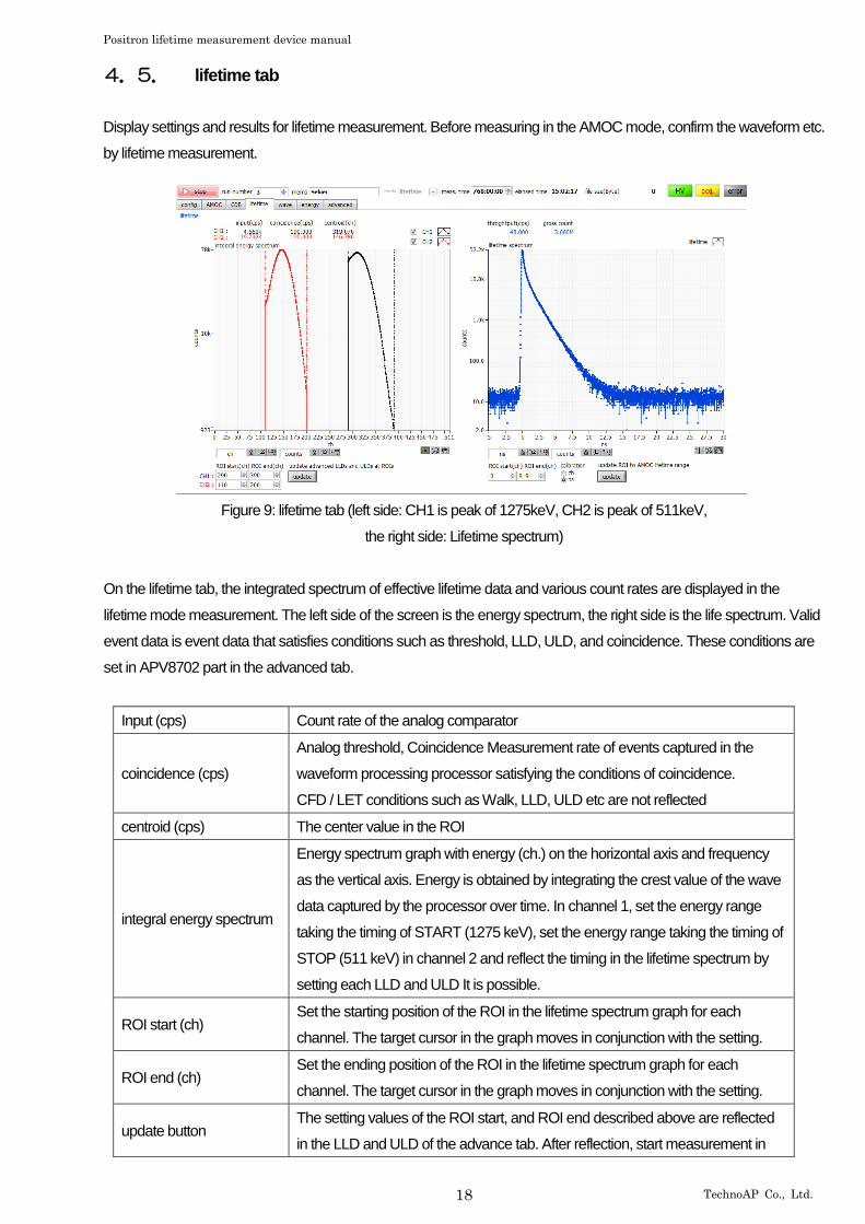
4.5. lifetime tab
Display settings and results for lifetime measurement. Before measuring in the AMOC mode, confirm the waveform etc.
by lifetime measurement.
Figure 9: lifetime tab (left side: CH1 is peak of 1275keV, CH2 is peak of 511keV,
the right side: Lifetime spectrum)
On the lifetime tab, the integrated spectrum of effective lifetime data and various count rates are displayed in the
lifetime mode measurement. The left side of the screen is the energy spectrum, the right side is the life spectrum. Valid
event data is event data that satisfies conditions such as threshold, LLD, ULD, and coincidence. These conditions are
set in APV8702 part in the advanced tab.
Input (cps) Count rate of the analog comparator
coincidence (cps)
Analog threshold, Coincidence Measurement rate of events captured in the
waveform processing processor satisfying the conditions of coincidence.
CFD / LET conditions such as Walk, LLD, ULD etc are not reflected
centroid (cps) The center value in the ROI
integral energy spectrum
Energy spectrum graph with energy (ch.) on the horizontal axis and frequency
as the vertical axis. Energy is obtained by integrating the crest value of the wave
data captured by the processor over time. In channel 1, set the energy range
taking the timing of START (1275 keV), set the energy range taking the timing of
STOP (511 keV) in channel 2 and reflect the timing in the lifetime spectrum by
setting each LLD and ULD It is possible.
ROI start (ch) Set the starting position of the ROI in the lifetime spectrum graph for each
channel. The target cursor in the graph moves in conjunction with the setting.
ROI end (ch) Set the ending position of the ROI in the lifetime spectrum graph for each
channel. The target cursor in the graph moves in conjunction with the setting.
update button The setting values of the ROI start, and ROI end described above are reflected
in the LLD and ULD of the advance tab. After reflection, start measurement in

Positron lifetime measurement device manual
19 TechnoAP Co., Ltd.
AMOC mode or lifetime mode and update the lifetime spectrum graph based on
the time information of events selected within the applicable energy range.
For example, if you set the range of 1275 keV at Na-22 at CH1 and the peak at
511 keV at CH2 with ROI start and ROI end respectively, you can acquire the
time difference spectrum at 1275 keV detection time - (minus) 511 keV detection
time.
lifetime spectrum
The horizontal axis represents the time difference between CH1 and CH2, and
the vertical axis represents the life spectrum. The time difference is calculated as
the time difference between the discrimination timing of CH1 and CH2 by taking
the CFD timing for the wave data captured by the processor. CH1 is started,
CH2 is STOP.
throughput (cps) Analog threshold, coincidence, rise threshold, CFD_walk, CFD_threshold, LLD,
ULD This is the count rate of valid events satisfying the conditions.
gross count Sum of counts
calibration Switch the units on the horizontal axis with “ch” or “ns”

Positron lifetime measurement device manual
20 TechnoAP Co., Ltd.
4.6. wave tab
Check the output signal from the BaF2 scintillation detector. Before measuring in lifetime mode or AMOC mode, check
whether the waveform is saturating, and whether the baseline or threshold is appropriate.
Figure 10: wave tab
wave (graph)
Display wave data captured from the ADC during wave mode measurement as a
graph. The horizontal axis represents sampling number / time, and the vertical axis
represents ADC code (0 to 255)
Input (cps) Count rate of analog comparator
coincidence (cps)
Analog threshold, coincidence Measurement rate of events captured in the processor
satisfying the condition. CFD / LET conditions such as CFD walk, LLD, ULD etc are
not reflected
accumulation Selection of presence or absence of afterimage function of wave data.
When the check is ON, there is afterimage present
calibration Select unit of horizontal axis from “ch” or “ns”

Positron lifetime measurement device manual
21 TechnoAP Co., Ltd.
4.7. energy tab
This tab is used in energy mode. The preamplifier output signal of the Germanium semiconductor detector is
waveform-shaped using APV8002, and the calculation result of energy spectrum, count rate, ROI is displayed based
on that data. It is also used for AMOC mode and CDB mode adjustment.
Figure 11: energy tab
input total count Number of events with input.
throughput count Number processed for input.
input count rate (cps) Number of events with inputs per second.
throughput count (cps) Number of events processed per second input
pileup rate (cps) Number of pile-up counts per second.
dead time ratio (%) Dead time ratio. Instantaneous value for each acquisition
energy spectrum Energy spectrum. Histogram of horizontal axis energy, vertical axis frequency.
ROI CH Select the target channel for ROI calculation from ROI 1 to ROI 8.
ROI start (ch) Sets the start position of the ROI. Unit is ch
ROI end (ch) Sets the end position of the ROI. Unit is ch
energy Define the energy value of the peak position (ch.). In the case of Co-60, it is set to
1173 or 1332 (keV).
Y mapping Select the mapping of the Y axis of the graph by linear or log (logarithmic). According
to the setting, the label of Y axis is also changed.
update Copy the setting of ROI 1 to the range of energy (momentum) graph in AMOC mode.
calibration Select the unit of X axis. The labels of the X axis are also changed according to the
setting.
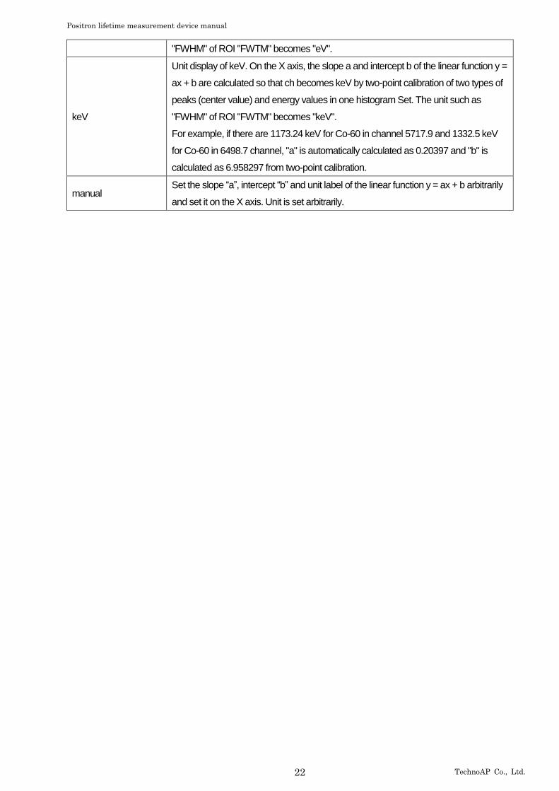
ch Display in ch (channel) unit. The unit such as "FWHM" of "FWTM" of ROI is arbitrary.
eV
Unit display of eV. On the X axis, the gradient a and intercept b of the linear function y
= ax + b are calculated so that ch becomes eV by two-point calibration of two kinds of
peaks (center value) and energy values in one histogram Set. The unit such as
Positron lifetime measurement device manual
22 TechnoAP Co., Ltd.
"FWHM" of ROI "FWTM" becomes "eV".
keV
Unit display of keV. On the X axis, the slope a and intercept b of the linear function y =
ax + b are calculated so that ch becomes keV by two-point calibration of two types of
peaks (center value) and energy values in one histogram Set. The unit such as
"FWHM" of ROI "FWTM" becomes "keV".
For example, if there are 1173.24 keV for Co-60 in channel 5717.9 and 1332.5 keV
for Co-60 in 6498.7 channel, "a" is automatically calculated as 0.20397 and "b" is
calculated as 6.958297 from two-point calibration.
manual Set the slope “a”, intercept “b” and unit label of the linear function y = ax + b arbitrarily
and set it on the X axis. Unit is set arbitrarily.
Positron lifetime measurement device manual
23 TechnoAP Co., Ltd.
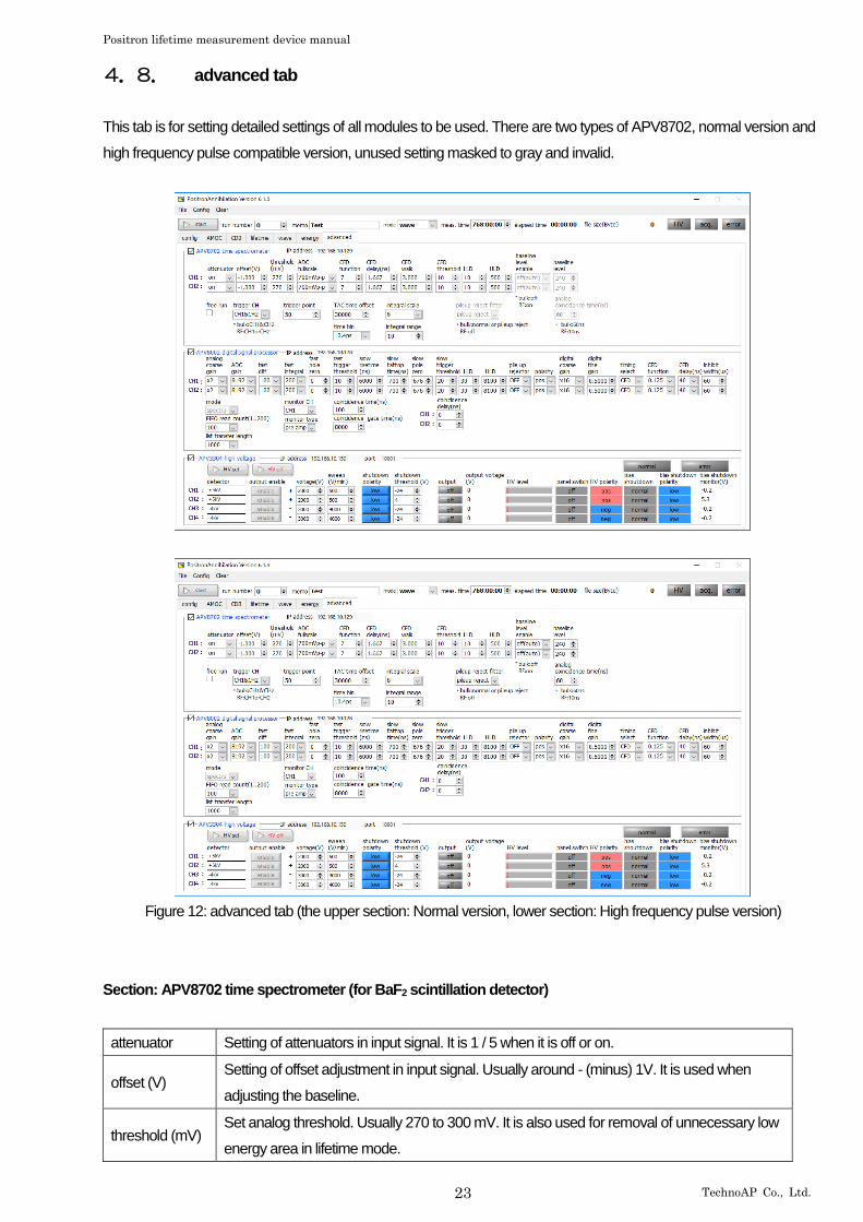
4.8. advanced tab
This tab is for setting detailed settings of all modules to be used. There are two types of APV8702, normal version and
high frequency pulse compatible version, unused setting masked to gray and invalid.
Figure 12: advanced tab (the upper section: Normal version, lower section: High frequency pulse version)
Section: APV8702 time spectrometer (for BaF2 scintillation detector)
attenuator Setting of attenuators in input signal. It is 1 / 5 when it is off or on.
offset (V) Setting of offset adjustment in input signal. Usually around - (minus) 1V. It is used when
adjusting the baseline.
threshold (mV) Set analog threshold. Usually 270 to 300 mV. It is also used for removal of unnecessary low
energy area in lifetime mode.
Positron lifetime measurement device manual
24 TechnoAP Co., Ltd.
ADC fullscale Analog full-scale range of ADC. Input voltage at the input terminal when attenuator is turned
off.
CFD function Setting relating to original magnification reduction ratio of CFD. The usual setting value is 6
or 7.
CFD delay (ns) Setting related to CFD delay time. The usual setting value is 1.333 or 1.667.
CFD walk Setting related to CFD walk. The usual setting value is 3.
CFD threshold Setting related to CFD threshold. The usual setting value is 10.
*Supplement*
In this device, CFD (Constant Fraction Discriminator) processing is performed from the captured waveform to calculate
the zero-cross timing of each CH. Since CFD processing waveform cannot be confirmed, the above four settings are
gradually changed and adjusted while confirming with the life spectrum.
LLD
It is setting the lower limit value of Integral energy Spectrum. Based on peaks at
1275 keV and 511 keV in the energy spectrum of Na-22, it is used as the lower
threshold for narrowing the timing.
ULD
It is setting the upper limit value of Integral energy Spectrum. Based on peaks at
1275 keV and 511 keV in the energy spectrum of Na-22, it is used as the upper
threshold for narrowing the timing.
baseline level enables
Select whether to use fixed base line level. When it is off (auto), the baseline level is
determined by computation from near the waveform capture. If on, use the value of
the next baseline level as the fixed baseline level. It is effective only with high
frequency (RF) pulse compatible version. This is a countermeasure in cases where
the high-frequency pulse is included in the baseline calculation range and the
baseline cannot be calculated correctly.
baseline level When the above baseline level enable is turned on Set the set value here to a fixed
baseline level. The usual setting value is 240.
free run
If you check this, you can internally generate a 10 Hz trigger signal and continuously
acquire waveform data. It is used for the above offset adjustment, noise level
checking, etc.
trigger ch
Select the channel to be triggered. (CH. 1 / CH. 2 / CH. 1 & CH. 2). For bulk
measurement, use Channel 1 & Channel 2 which is simultaneous measurement.
For high frequency (RF) pulse compatible version, use single trigger of Channel 1 or
Channel 2.
trigger point Trigger timing setting in wave mode. The usual setting value is 50 digits.
TAC time offset
Set time offset of life time spectrum in lifetime mode. The usual setting value is
30000. The setting value in case of high frequency (RF) pulse compatible version is
0 (zero).
time bin
This is a setting of the time width per bin of lifetime spectrum graph in lifetime mode.
The measurement range is ± 60 ns due to the circuit configuration. The usual
setting value is 10.4 ps.
integral scale Setting of horizontal scale conversion of integral energy spectrum. Set the
Positron lifetime measurement device manual
25 TechnoAP Co., Ltd.
waveform integration result to 1 (one) / set value. When the gain is high, and the
integration range is wide, the integration result becomes a large value, so adjust it to
fit 512 Channel.
integral range Setting concerning integral range of integral energy spectrum. The usual setting
value is 10.
pileup rejector filter
Pileup up reject is a function to eliminate the waveform as inappropriate for
arithmetic processing, such as overlapping waveforms. Usually select normal
(minimum required reject) or pileup reject. For high frequency (RF) pulse compatible
version, set it to off.
analog coincidence time
Upper limit of the range regarded as simultaneous due to the configuration of the
circuit. Normal setting value is 60 ns. 0 (zero) for frequency (RF) pulse compatible
version.

Positron lifetime measurement device manual
26 TechnoAP Co., Ltd.
Section: APV8002 digital signal processor (for Germanium semiconductor detector)
analog coarse gain
Analog coarse gain. Amplification magnification of the preamplifier output signal
captured inside. Selected from 1, 2, 5, 10 times. Connect the oscilloscope to the
MONI output terminal on the front panel of the board and adjust the signal level so
that the signal level falls within 0 (zero) to 1 V by setting the monitor type to preamp
as described later.
ADC gain Gain of ADC (Number of channels or bins) Normal setting value is 8192 channels.
fast diff Constant of fast differential circuit. The usual setting value is 200.
fast integral Constant of fast integrating circuit. The usual setting value is 200.
fast pole zero Setting of fast pole zero cancellation. Normal setting value is 0 (zero) (automatic
setting).
fast trigger threshold
This is the threshold value of the waveform acquisition start timing using the fast
filter. The unit is digit. Normal setting value is 10 to 20. If the noise level is high, it
may be 30 or more. While checking the count rate of input total rate (cps), set it to a
value slightly larger than the noise level where the value becomes extremely large.
Based on the preamplifier output signal, a fast filter waveform with differentiation and
integration processing of the timing filter amplifier circuit is generated. When it
reaches or exceeds this threshold in that waveform, we obtain the timing information
acquisition timing at that point and the timing of the start of filter waveform
generation in the spectroscopy amplifier circuit. It mainly relates to time acquisition
(time stamp).
slow risetime(ns)
Sets the rise time of the slow filter. It is usually 6000 ns (linear amp equivalent to 3
μsec). If it is set small, the count increases but the energy resolution becomes
worse.
slow flattop time(ns) Sets the flat top time of the slow filter. It is usually 700 ns
slow pole zero
Set slow pole zero cancellation. Connect the oscilloscope to the MONI output
terminal on the front panel of the board, adjust the monitor type to slow as described
below, and adjust the pole zero so that there is no overshoot or undershoot near the
baseline.
Figure 13: rise time and flattop time and pole zero
rise time flattop time
(Peaking time) pole zero
Positron lifetime measurement device manual
27 TechnoAP Co., Ltd.
slow trigger threshold
Sets the threshold of the start timing of waveform acquisition using the slow filter.
Normal setting value is 20 to 30. Set it slightly above the noise level and within the
range below the LLD described below. Set it to a value slightly larger than the noise
level where the value becomes extremely large while confirming the count rate of
throughput rate (cps). When the filter waveform of the generated spectroscopic
amplifier reaches or exceeds this threshold value, peak value at a preset time (slow
rise time + slow flattop time) is acquired.
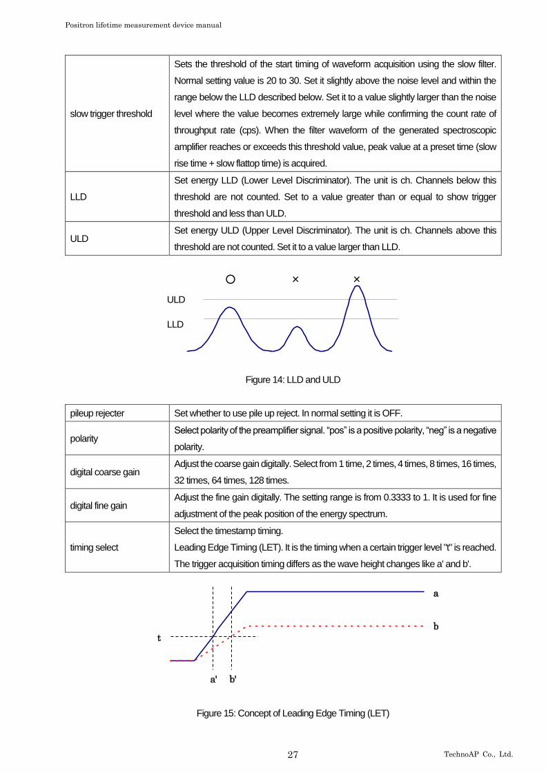
LLD
Set energy LLD (Lower Level Discriminator). The unit is ch. Channels below this
threshold are not counted. Set to a value greater than or equal to show trigger
threshold and less than ULD.
ULD Set energy ULD (Upper Level Discriminator). The unit is ch. Channels above this
threshold are not counted. Set it to a value larger than LLD.
○ × ×
Figure 14: LLD and ULD
pileup rejecter Set whether to use pile up reject. In normal setting it is OFF.
polarity Select polarity of the preamplifier signal. “pos” is a positive polarity, “neg” is a negative
polarity.
digital coarse gain Adjust the coarse gain digitally. Select from 1 time, 2 times, 4 times, 8 times, 16 times,
32 times, 64 times, 128 times.
digital fine gain Adjust the fine gain digitally. The setting range is from 0.3333 to 1. It is used for fine
adjustment of the peak position of the energy spectrum.
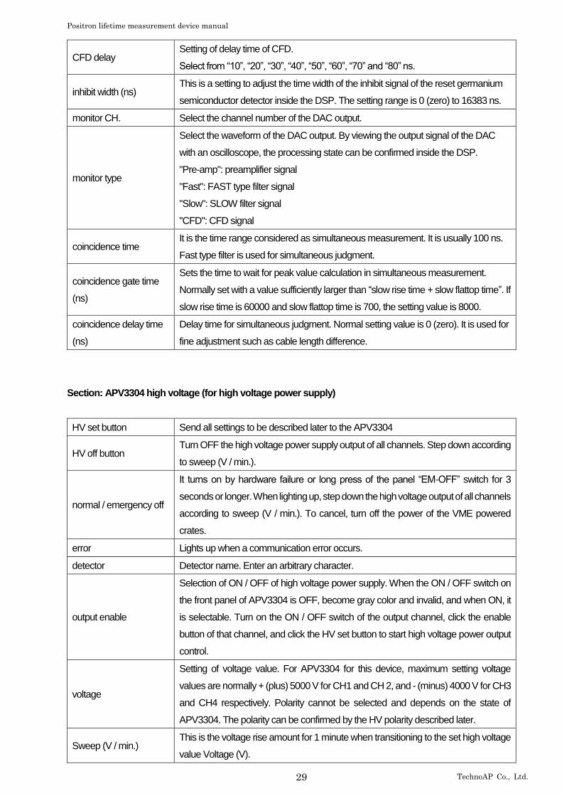
timing select
Select the timestamp timing.
Leading Edge Timing (LET). It is the timing when a certain trigger level "t" is reached.
The trigger acquisition timing differs as the wave height changes like a' and b'.
Figure 15: Concept of Leading Edge Timing (LET)
ULD
LLD
b
a
b' a'
t

Positron lifetime measurement device manual
28 TechnoAP Co., Ltd.
g
h
CFD
Constant Fraction Discriminator Timing (CFD)
Input signal
Delay an input signal for CFD Delay
Add inversion and a delay
Figure 16: Concept of Constant Fraction Decorrelator Timing (CFD)
For the different waveforms a and b in the above figure, generate waveforms like the following waveforms "c and d", "e
and f", "g and h".
Waveforms c and d Waveforms a and b are multiplied by CFD function, inverted waveform
Waveforms e and f Waveforms a and b delayed by CFD delay
Waveforms g and h
A waveform obtained by adding waveforms c and e and a waveform obtained by
adding waveforms d and f
CFD, which is the zero-crossing timing of waveforms g and h, has a characteristic
that it is constant even if the wave height changes if the rise time of the waveform is
the same.
CFD function Magnification for reducing the original waveform for calculation of CFD.
Select from “0.125”, “0.25”, “0.375”, “0.4”, “0.5”, “0.625”, “0.75”, and “0.875”.
e
f
c V1*CFD function
CFD delay
b
a
d
V1
V2
V2*CFD function
Input signal multiplied by CFD function and inverted
Positron lifetime measurement device manual
29 TechnoAP Co., Ltd.
CFD delay Setting of delay time of CFD.
Select from “10”, “20”, “30”, “40”, “50”, “60”, “70” and “80” ns.
inhibit width (ns) This is a setting to adjust the time width of the inhibit signal of the reset germanium
semiconductor detector inside the DSP. The setting range is 0 (zero) to 16383 ns.
monitor CH. Select the channel number of the DAC output.
monitor type
Select the waveform of the DAC output. By viewing the output signal of the DAC
with an oscilloscope, the processing state can be confirmed inside the DSP.
"Pre-amp": preamplifier signal
"Fast": FAST type filter signal
"Slow": SLOW filter signal
"CFD": CFD signal
coincidence time It is the time range considered as simultaneous measurement. It is usually 100 ns.
Fast type filter is used for simultaneous judgment.
coincidence gate time
(ns)
Sets the time to wait for peak value calculation in simultaneous measurement.
Normally set with a value sufficiently larger than “slow rise time + slow flattop time”. If
slow rise time is 60000 and slow flattop time is 700, the setting value is 8000.
coincidence delay time
(ns)
Delay time for simultaneous judgment. Normal setting value is 0 (zero). It is used for
fine adjustment such as cable length difference.
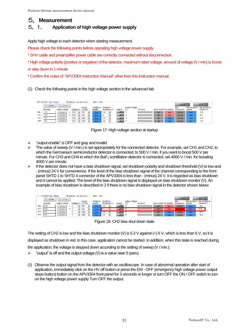
Section: APV3304 high voltage (for high voltage power supply)
HV set button Send all settings to be described later to the APV3304
HV off button Turn OFF the high voltage power supply output of all channels. Step down according
to sweep (V / min.).
normal / emergency off
It turns on by hardware failure or long press of the panel “EM-OFF” switch for 3
seconds or longer. When lighting up, step down the high voltage output of all channels
according to sweep (V / min.). To cancel, turn off the power of the VME powered
crates.
error Lights up when a communication error occurs.
detector Detector name. Enter an arbitrary character.
output enable
Selection of ON / OFF of high voltage power supply. When the ON / OFF switch on
the front panel of APV3304 is OFF, become gray color and invalid, and when ON, it
is selectable. Turn on the ON / OFF switch of the output channel, click the enable
button of that channel, and click the HV set button to start high voltage power output
control.
voltage
Setting of voltage value. For APV3304 for this device, maximum setting voltage
values are normally + (plus) 5000 V for CH1 and CH 2, and - (minus) 4000 V for CH3
and CH4 respectively. Polarity cannot be selected and depends on the state of
APV3304. The polarity can be confirmed by the HV polarity described later.
Sweep (V / min.) This is the voltage rise amount for 1 minute when transitioning to the set high voltage
value Voltage (V).

Positron lifetime measurement device manual
30 TechnoAP Co., Ltd.
*Caution*
Setting a large value will rapidly supply high voltage to the detector. It is
necessary to set it to an appropriate value so that the equipment such as the
detector does not break down.
shutdown polarity
Set the polarity to be the bias shutdown at the signal input terminal from SHTD 1 for
CH1 on the front panel of APV3304 to SHTD 4 for CH4. Used with the shutdown
threshold (V) described below. For example, if shutdown polarity is set to low and
shutdown threshold (V) is set to 4 (V) as shown in CH2 in the above figure and 5.3
V is applied to SHTD 2, if a voltage of 4 V or less is applied to the SHTD 2 terminal,
bias shutdown control start. Specification of bias shutdown differs depending on
detector manufacturer and model, so it is necessary to fully confirm beforehand.
shutdown threshold (V)
APV3304 Setting of the threshold for bias shutdown at the signal input terminal from
SHTD 1 for CH1 of the front panel to SHTD 4 for CH4. Used with the shutdown
polarity mentioned above.
output
Displays the output status of the high voltage power supply.
“Off”: High voltage output OFF
“Flashing”: Transiting to the set high voltage
“On”: Outputting the set high voltage
output voltage (V)
Displays the current output voltage value. Accuracy is about ± 5% specifications of
mounted high voltage power supply. In this specification the monitor accuracy at 1%
or less of the rated output is not guaranteed. Since the output voltage has load
dependency, the display may be different from the set voltage (V) depending on the
magnitude of the load.
HV level Displays the current output voltage value with a progress bar. It is maximum + (plus)
or –(minus) 5000V.
panel switch The status of the front panel ON / OFF switch is displayed.
HV polarity
Displays the polarity of the high voltage power supply mounted on the APV3304.
Normal CH1 and CH2 are pos (positive polarity), CH3 and CH4 are neg (negative
polarity).
bias shutdown
It lights up when the bias shutdown condition is satisfied. The condition depends on
the specification of the bias shutdown signal of the detector and the setting of
shutdown polarity and shutdown threshold (V) as described above.
shutdown polarity Display setting status of the above shutdown polarity.
bias shutdown monitor
(V)
Displays the voltage value (V) of the signal input from SHTD 1 to SHTD 4. The
above shutdown polarity and shutdown threshold (V) settings are determined based
on this value. If the output impedance of the detector is high, it may not be displayed
correctly.
Positron lifetime measurement device manual
31 TechnoAP Co., Ltd.
5. Measurement
5.1. Application of high voltage power supply
Apply high voltage to each detector when starting measurement.
Please check the following points before operating high voltage power supply.
* SHV cable and preamplifier power cable are correctly connected without disconnection.
* High voltage polarity (positive or negative) of the detector, maximum rated voltage, amount of voltage (V / min) to boost
or step down in 1 minute
* Confirm the notes of "APV3304 Instruction Manual" other than this instruction manual.
(1) Check the following points in the high voltage section in the advanced tab.
Figure 17: High voltage section at startup
➢ “output enable” is OFF and gray and invalid. ➢ The value of sweep (V / min.) is set appropriately for the connected detector. For example, set CH1 and CH2, to
which the Germanium semiconductor detector is connected, to 500 V / min. if you want to boost 500 V per minute. For CH3 and CH4 to which the BaF2 scintillation detector is connected, set 4000 V / min. for boosting 4000 V per minute.
➢ If the detector does not have a bias shutdown signal, set shutdown polarity and shutdown threshold (V) to low and - (minus) 24 V for convenience. If the level of the bias shutdown signal of the channel corresponding to the front panel SHTD 1 to SHTD 4 connector of the APV3304 is less than - (minus) 24 V, it is regarded as bias shutdown and it cannot be applied. The level of the bias shutdown signal is displayed on bias shutdown monitor (V). An example of bias shutdown is described in 2 if there is no bias shutdown signal in the detector shown below
Figure 18: CH2 bias shut down state
The setting of CH2 is low and the bias shutdown monitor (V) is 5.3 V against (+) 6 V, which is less than 6 V, so it is
displayed as shutdown in red. In this case, application cannot be started. In addition, when this state is reached during
the application, the voltage is stepped down according to the setting of sweep (V / min.).
➢ “output” is off and the output voltage (V) is a value near 0 (zero).
(2) Observe the output signal from the detector with an oscilloscope. In case of abnormal operation after start of application, immediately click on the HV off button or press the EM - OFF (emergency high voltage power output stops button) button on the APV3304 front panel for 3 seconds or longer or turn OFF the ON / OFF switch to turn on the high voltage power supply Turn OFF the output.
Positron lifetime measurement device manual
32 TechnoAP Co., Ltd.
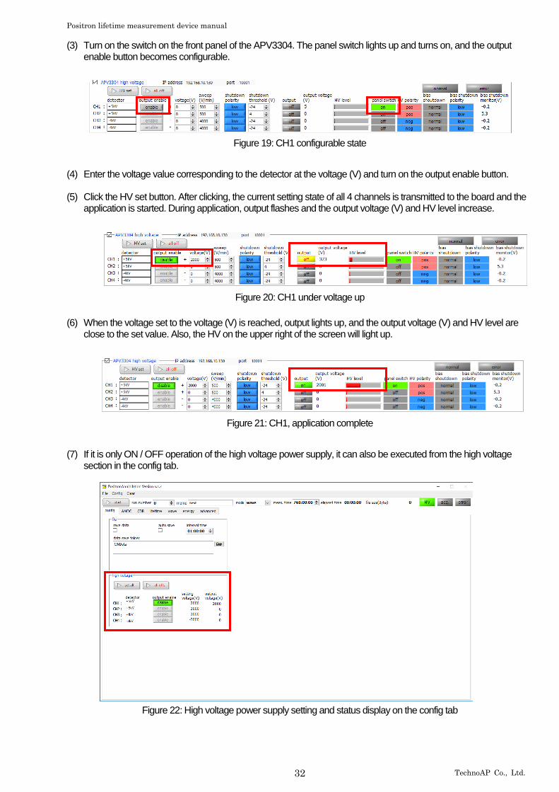
(3) Turn on the switch on the front panel of the APV3304. The panel switch lights up and turns on, and the output enable button becomes configurable.
Figure 19: CH1 configurable state
(4) Enter the voltage value corresponding to the detector at the voltage (V) and turn on the output enable button.
(5) Click the HV set button. After clicking, the current setting state of all 4 channels is transmitted to the board and the application is started. During application, output flashes and the output voltage (V) and HV level increase.
Figure 20: CH1 under voltage up
(6) When the voltage set to the voltage (V) is reached, output lights up, and the output voltage (V) and HV level are
close to the set value. Also, the HV on the upper right of the screen will light up.
Figure 21: CH1, application complete
(7) If it is only ON / OFF operation of the high voltage power supply, it can also be executed from the high voltage section in the config tab.
Figure 22: High voltage power supply setting and status display on the config tab

Positron lifetime measurement device manual
33 TechnoAP Co., Ltd.
5.2. energy mode
In the energy mode, gamma ray energy spectrum measurement is performed using APV 8002 alone.
5.2.1. Environment
(1) When using energy mode, please connect this equipment as shown below.
VME Power SuppliesAPV9007
PC
Ge #1Preamp
511keV 511keV
Ge #2 Preamp
Sample
Time Spectrometer APV8702
Energy Spectrometer APV8002
Preamp Power APV4004
High Voltage APV3304
SwitchingHub
PositronAnnihilationApplication
CH1
CH2
CH1CH2
CH1
CH2
Oscilloscope
MONI
Figure 23: Connection diagrams of energy mode
5.2.2. Adjustment
(1) Make the following settings in the advanced tab. The settings in the figure below are guidelines and may vary depending on the environment.
Figure 24: Energy mode setting (approximate)
➢ Select energy in mode. ➢ Set the parameters of APV8002 with reference to the above figure. For the explanation of each
parameter, refer to "4.8.advanced tab" and separate DSP software manual. ➢ Set “meas. time” to the maximum of 768 hours. ➢ During adjustment, if save data is set to OFF in the config tab, data is not saved for each measurement. ➢ Connect the oscilloscope to the MONI terminal on the front panel of the APV8002. By connecting, the
state of signal processing inside the APV8002 can be confirmed as an oscilloscope as a waveform, and the gain and the pole zero can be adjusted. As a guide for setting the oscilloscope, the horizontal axis is 100 μsec / Div., And the vertical axis is 100 mV / Div.
➢ Click Config on the menu and send the settings to APV8002.

Positron lifetime measurement device manual
34 TechnoAP Co., Ltd.
(2) Prepare for adjustment of the analog system. The analog system is the setting on the APV8002 side according to the preamplifier output signal of the Germanium semiconductor detector. ➢ Set polarity of detector with polarity. Set “pos” for positive polarity and “neg” for negative polarity. ➢ The analog coarse gain should be × 2 times or × 5 times. ➢ Set monitor CH to “CH1” and monitor type to “preamp”. You can check the preamplifier signal in the
APV8002 of CH 1 from the MONI terminal on the oscilloscope. Check that the signal of the preamplifier is within the range of 0 (zero) to + (plus) 1 V and does not saturate.
Positron lifetime measurement device manual
35 TechnoAP Co., Ltd.
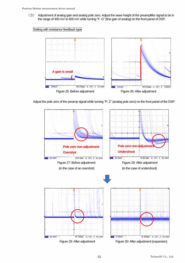
(3) Adjustment of analog gain and analog pole zero. Adjust the wave height of the preamplifier signal to be in the range of 400 mV to 600 mV while turning "F. G" (fine gain of analog) on the front panel of DSP.
Setting with resistance feedback type
Figure 25: Before adjustment Figure 26: After adjustment
Adjust the pole zero of the preamp signal while turning "P. Z" (analog pole zero) on the front panel of the DSP.
Figure 27: Before adjustment Figure 28: After adjustment
(in the case of an overshot) (in the case of undershoot)
Figure 29: After adjustment Figure 30: After adjustment (expansion)
Pole zero non-adjustment
Overshot
Pole zero non-adjustment
Undershoot
A gain is small
Positron lifetime measurement device manual
36 TechnoAP Co., Ltd.
Setting of the reset type
① Check the preamplifier output signal from the "MONI" terminal on the front panel of the DSP with an oscilloscope
② Turn the "P. Z" (analog pole zero) on the front panel of the DSP counterclockwise until the tone sounds "tick".
③ While turning "F. G" (Analog fine gain) on the front panel of the DSP, adjust the wave height of the preamplifier signal
from 400 mV to 600 mV.
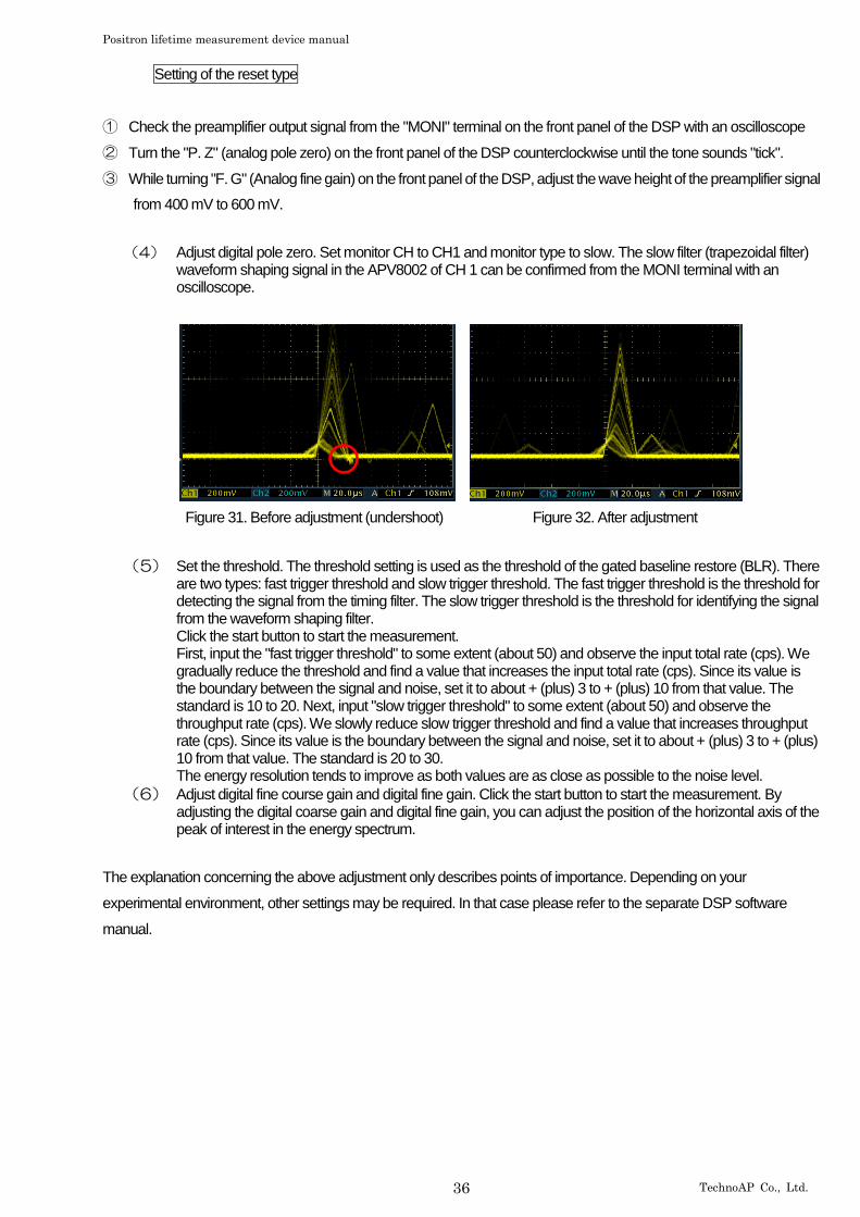
(4) Adjust digital pole zero. Set monitor CH to CH1 and monitor type to slow. The slow filter (trapezoidal filter) waveform shaping signal in the APV8002 of CH 1 can be confirmed from the MONI terminal with an oscilloscope.
Figure 31. Before adjustment (undershoot) Figure 32. After adjustment
(5) Set the threshold. The threshold setting is used as the threshold of the gated baseline restore (BLR). There are two types: fast trigger threshold and slow trigger threshold. The fast trigger threshold is the threshold for detecting the signal from the timing filter. The slow trigger threshold is the threshold for identifying the signal from the waveform shaping filter. Click the start button to start the measurement. First, input the "fast trigger threshold" to some extent (about 50) and observe the input total rate (cps). We gradually reduce the threshold and find a value that increases the input total rate (cps). Since its value is the boundary between the signal and noise, set it to about + (plus) 3 to + (plus) 10 from that value. The standard is 10 to 20. Next, input "slow trigger threshold" to some extent (about 50) and observe the throughput rate (cps). We slowly reduce slow trigger threshold and find a value that increases throughput rate (cps). Since its value is the boundary between the signal and noise, set it to about + (plus) 3 to + (plus) 10 from that value. The standard is 20 to 30. The energy resolution tends to improve as both values are as close as possible to the noise level.
(6) Adjust digital fine course gain and digital fine gain. Click the start button to start the measurement. By adjusting the digital coarse gain and digital fine gain, you can adjust the position of the horizontal axis of the peak of interest in the energy spectrum.
The explanation concerning the above adjustment only describes points of importance. Depending on your
experimental environment, other settings may be required. In that case please refer to the separate DSP software
manual.

Positron lifetime measurement device manual
37 TechnoAP Co., Ltd.
5.2.3. The measurement
Measurement is started after completion of the above adjustment.
(1) When measurement starts, the display automatically switches to the energy tab. During measurement, acq.LED flashes, indicating that the device and this application are communicating. Count rate information and energy spectrum graph are displayed. You can calibrate the energy on the horizontal axis of the graph by operating the ROI setting or display the calculation result on the ROI. For details of each setting, refer to "4.7.energy tab".
Figure 33: energy mode measurement screen (Na-22 spectrum)
➢ Measurement stops when elapsed time reaches “meas.time” or by clicking the start button (the
display automatically changes to stop after measurement starts).
➢ If the “save data” item is checked on the config tab, the measurement data and the config file are automatically saved when measurement stops. The save destination is the path displayed at the bottom of the config tab. Measurement data can also be saved by clicking save energy file in the menu bar after stopping measurement. For details on the config tab settings, see “4.2. Config tab”.

Positron lifetime measurement device manual
38 TechnoAP Co., Ltd.
5.3. CDB mode
In CDB mode, simultaneous events from two Germanium semiconductor detectors are acquired using APV8002 and
CDB (Coincidence Doppler Broadening) measurement is performed.
5.3.1. Environment
(1) When using the CDB mode, connect this device as shown below.
VME Power SuppliesAPV9007
PC
Ge #1Preamp
511keV 511keV
Ge #2 Preamp
Sample
Time Spectrometer APV8702
Energy Spectrometer APV8002
Preamp Power APV4004
High Voltage APV3304
SwitchingHub
PositronAnnihilationApplication
CH1
CH2
CH1CH2
CH1
CH2
Oscilloscope
MONI
Figure 34: Connection diagram of CDB mode
5.3.2. Adjustment
(1) Measurement is performed by switching the operation mode to energy mode. Adjust the advance tab so that a peak of 511 keV appears in CH1 and CH2 of the energy spectrum graph of the energy tab. For operations on energy mode, see “5.2. energy mode”.
(2) Set ROI start (ch) and ROI stop (ch) to peak at 511 keV peak in energy spectrum of energy tab. When set, the corresponding cursor will move in the graph (downward arrow in the figure below).
Figure 35: ROI setting
Positron lifetime measurement device manual
39 TechnoAP Co., Ltd.
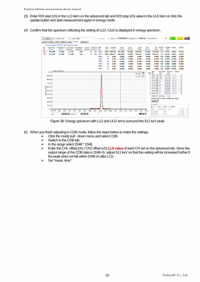
(3) Enter ROI start (ch) in the LLD item on the advanced tab and ROI stop (ch) value in the ULD item or click the update button and start measurement again in energy mode.
(4) Confirm that the spectrum reflecting the setting of LLD / ULD is displayed in energy spectrum.
Figure 36: Energy spectrum with LLD and ULD set to surround the 511 keV peak
(5) When you finish adjusting in CDB mode, follow the steps below to make the settings. ➢ Click the mode pull - down menu and select CDB. ➢ Switch to the CDB tab. ➢ In the range select 2048 * 2048. ➢ Enter the CHL offset (ch) / CH2 offset (ch) LLD value of each CH set on the advanced tab. Since the
output range of the CDB data is 2048 ch, adjust 511 keV so that this setting will be increased further if the peak does not fall within 2048 ch after LLD.
➢ Set “meas. time”.
Positron lifetime measurement device manual
40 TechnoAP Co., Ltd.
5.3.3. The measurement
Measurement is started after completion of the above adjustment.
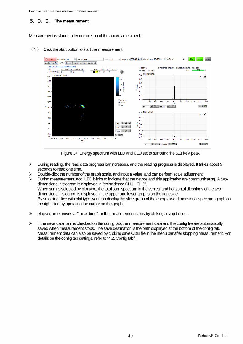
(1) Click the start button to start the measurement.
Figure 37: Energy spectrum with LLD and ULD set to surround the 511 keV peak
➢ During reading, the read data progress bar increases, and the reading progress is displayed. It takes about 5
seconds to read one time. ➢ Double-click the number of the graph scale, and input a value, and can perform scale adjustment. ➢ During measurement, acq. LED blinks to indicate that the device and this application are communicating. A two-
dimensional histogram is displayed in "coincidence CH1 - CH2". When sum is selected by plot type, the total sum spectrum in the vertical and horizontal directions of the two-dimensional histogram is displayed in the upper and lower graphs on the right side. By selecting slice with plot type, you can display the slice graph of the energy two-dimensional spectrum graph on the right side by operating the cursor on the graph.
➢ elapsed time arrives at “meas.time”, or the measurement stops by clicking a stop button.
➢ If the save data item is checked on the config tab, the measurement data and the config file are automatically
saved when measurement stops. The save destination is the path displayed at the bottom of the config tab. Measurement data can also be saved by clicking save CDB file in the menu bar after stopping measurement. For details on the config tab settings, refer to “4.2. Config tab”.
Positron lifetime measurement device manual
41 TechnoAP Co., Ltd.
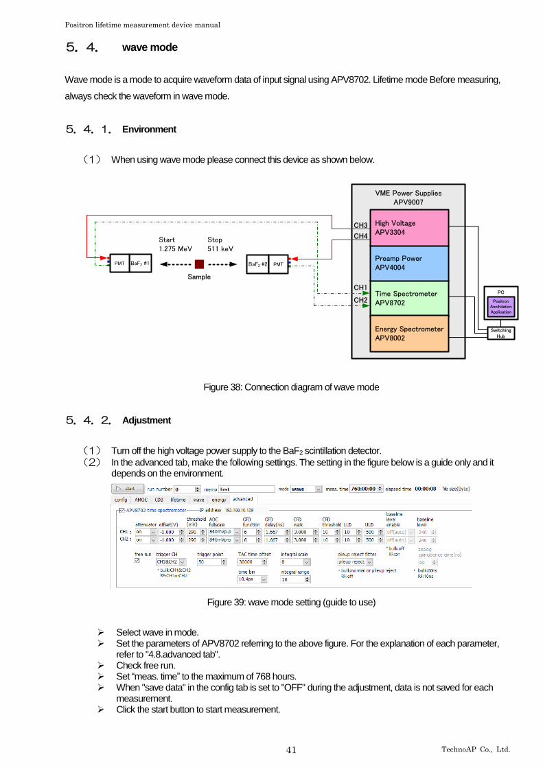
5.4. wave mode
Wave mode is a mode to acquire waveform data of input signal using APV8702. Lifetime mode Before measuring,
always check the waveform in wave mode.
5.4.1. Environment
(1) When using wave mode please connect this device as shown below.
VME Power SuppliesAPV9007
BaF2 #2 PMTBaF2 #1PMT
Start1.275 MeV
Sample
Stop511 keV
PC Time Spectrometer APV8702
Energy Spectrometer APV8002
Preamp Power APV4004
High Voltage APV3304
SwitchingHub
PositronAnnihilationApplication
CH3
CH4
CH1
CH2
Figure 38: Connection diagram of wave mode
5.4.2. Adjustment
(1) Turn off the high voltage power supply to the BaF2 scintillation detector.
(2) In the advanced tab, make the following settings. The setting in the figure below is a guide only and it depends on the environment.
Figure 39: wave mode setting (guide to use)
➢ Select wave in mode. ➢ Set the parameters of APV8702 referring to the above figure. For the explanation of each parameter,
refer to "4.8.advanced tab". ➢ Check free run. ➢ Set “meas. time” to the maximum of 768 hours. ➢ When "save data" in the config tab is set to "OFF" during the adjustment, data is not saved for each
measurement. ➢ Click the start button to start measurement.
Positron lifetime measurement device manual
42 TechnoAP Co., Ltd.
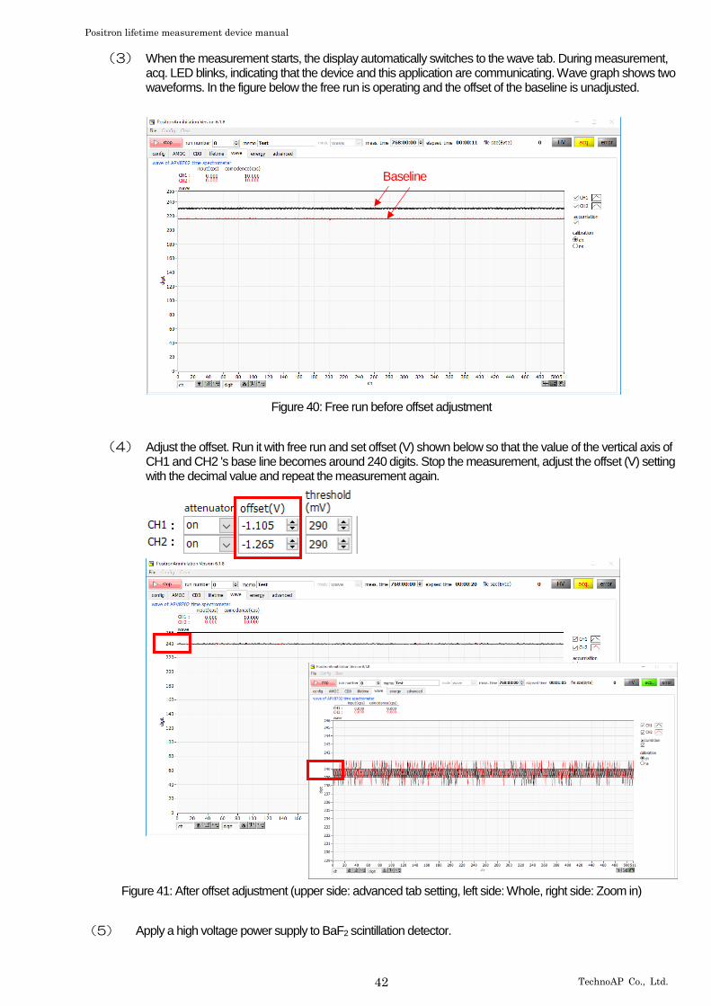
(3) When the measurement starts, the display automatically switches to the wave tab. During measurement, acq. LED blinks, indicating that the device and this application are communicating. Wave graph shows two waveforms. In the figure below the free run is operating and the offset of the baseline is unadjusted.
Figure 40: Free run before offset adjustment
(4) Adjust the offset. Run it with free run and set offset (V) shown below so that the value of the vertical axis of CH1 and CH2 's base line becomes around 240 digits. Stop the measurement, adjust the offset (V) setting with the decimal value and repeat the measurement again.
Figure 41: After offset adjustment (upper side: advanced tab setting, left side: Whole, right side: Zoom in)
(5) Apply a high voltage power supply to BaF2 scintillation detector.
Baseline
Positron lifetime measurement device manual
43 TechnoAP Co., Ltd.
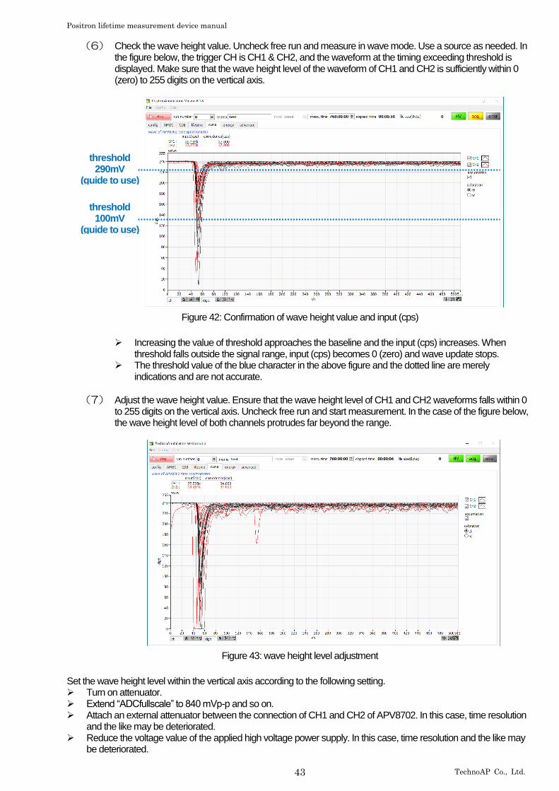
(6) Check the wave height value. Uncheck free run and measure in wave mode. Use a source as needed. In the figure below, the trigger CH is CH1 & CH2, and the waveform at the timing exceeding threshold is displayed. Make sure that the wave height level of the waveform of CH1 and CH2 is sufficiently within 0 (zero) to 255 digits on the vertical axis.
Figure 42: Confirmation of wave height value and input (cps)
➢ Increasing the value of threshold approaches the baseline and the input (cps) increases. When
threshold falls outside the signal range, input (cps) becomes 0 (zero) and wave update stops. ➢ The threshold value of the blue character in the above figure and the dotted line are merely
indications and are not accurate.
(7) Adjust the wave height value. Ensure that the wave height level of CH1 and CH2 waveforms falls within 0 to 255 digits on the vertical axis. Uncheck free run and start measurement. In the case of the figure below, the wave height level of both channels protrudes far beyond the range.
Figure 43: wave height level adjustment
Set the wave height level within the vertical axis according to the following setting. ➢ Turn on attenuator. ➢ Extend “ADCfullscale” to 840 mVp-p and so on. ➢ Attach an external attenuator between the connection of CH1 and CH2 of APV8702. In this case, time resolution
and the like may be deteriorated. ➢ Reduce the voltage value of the applied high voltage power supply. In this case, time resolution and the like may
be deteriorated.
threshold 290mV
(guide to use)
threshold 100mV
(guide to use)
Positron lifetime measurement device manual
44 TechnoAP Co., Ltd.
5.4.3. The measurement
The measurement is started after completion of the above adjustment.
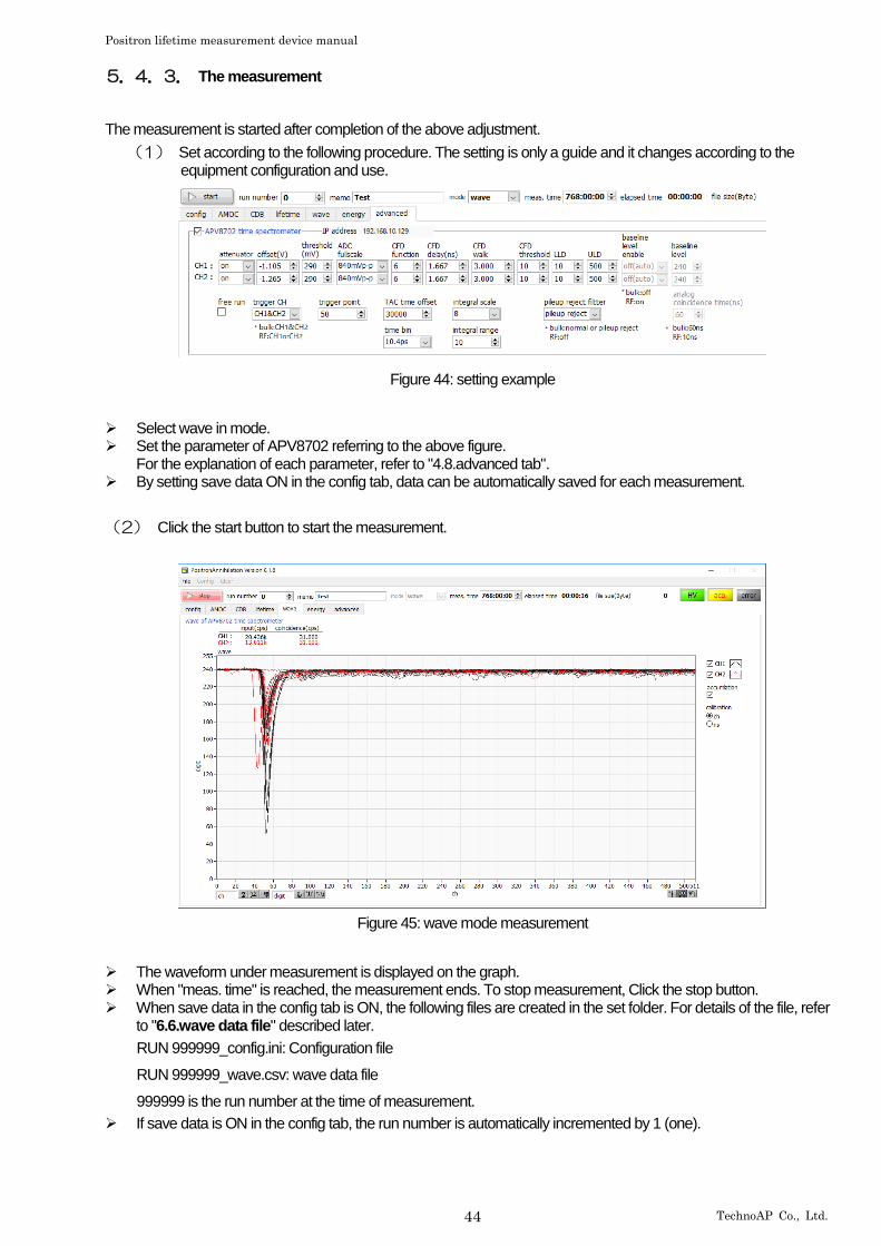
(1) Set according to the following procedure. The setting is only a guide and it changes according to the equipment configuration and use.
Figure 44: setting example
➢ Select wave in mode. ➢ Set the parameter of APV8702 referring to the above figure.
For the explanation of each parameter, refer to "4.8.advanced tab". ➢ By setting save data ON in the config tab, data can be automatically saved for each measurement.
(2) Click the start button to start the measurement.
Figure 45: wave mode measurement
➢ The waveform under measurement is displayed on the graph. ➢ When "meas. time" is reached, the measurement ends. To stop measurement, Click the stop button. ➢ When save data in the config tab is ON, the following files are created in the set folder. For details of the file, refer
to "6.6.wave data file" described later.
RUN 999999_config.ini: Configuration file
RUN 999999_wave.csv: wave data file
999999 is the run number at the time of measurement.
➢ If save data is ON in the config tab, the run number is automatically incremented by 1 (one).
Positron lifetime measurement device manual
45 TechnoAP Co., Ltd.
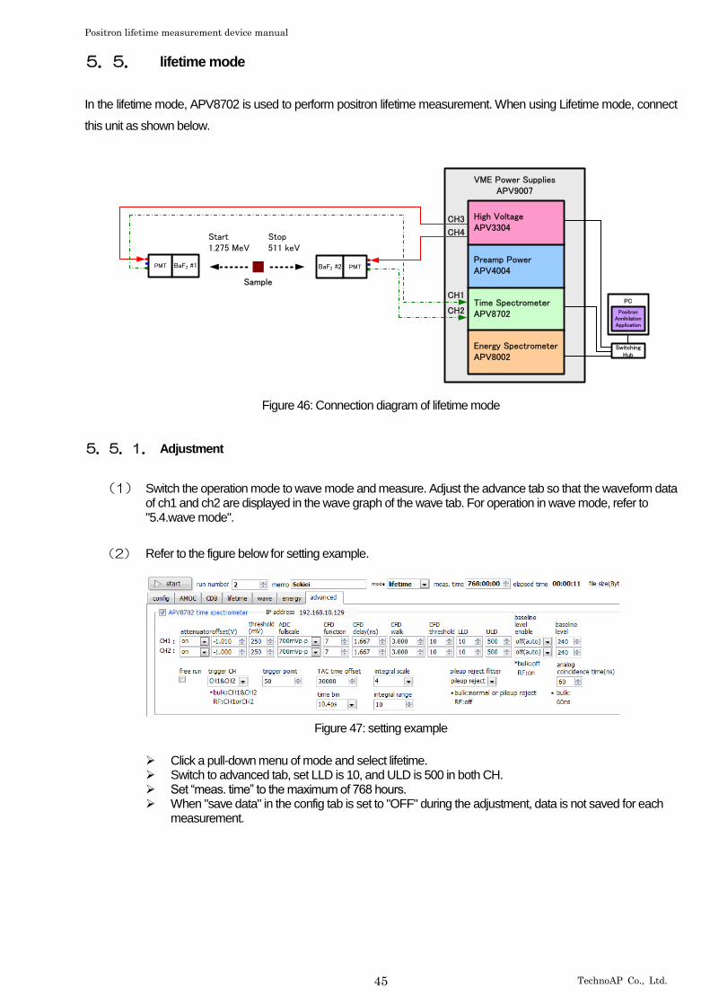
5.5. lifetime mode
In the lifetime mode, APV8702 is used to perform positron lifetime measurement. When using Lifetime mode, connect
this unit as shown below.
VME Power SuppliesAPV9007
BaF2 #2 PMTBaF2 #1PMT
Start1.275 MeV
Sample
Stop511 keV
PC Time Spectrometer APV8702
Energy Spectrometer APV8002
Preamp Power APV4004
High Voltage APV3304
SwitchingHub
PositronAnnihilationApplication
CH3
CH4
CH1
CH2
Figure 46: Connection diagram of lifetime mode
5.5.1. Adjustment
(1) Switch the operation mode to wave mode and measure. Adjust the advance tab so that the waveform data of ch1 and ch2 are displayed in the wave graph of the wave tab. For operation in wave mode, refer to "5.4.wave mode".
(2) Refer to the figure below for setting example.
Figure 47: setting example
➢ Click a pull-down menu of mode and select lifetime. ➢ Switch to advanced tab, set LLD is 10, and ULD is 500 in both CH. ➢ Set “meas. time” to the maximum of 768 hours. ➢ When "save data" in the config tab is set to "OFF" during the adjustment, data is not saved for each
measurement.
Positron lifetime measurement device manual
46 TechnoAP Co., Ltd.
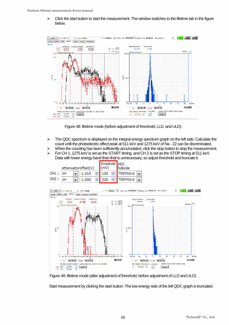
➢ Click the start button to start the measurement. The window switches to the lifetime tab in the figure below.
Figure 48: lifetime mode (before adjustment of threshold, LLD, and ULD)
➢ The QDC spectrum is displayed on the integral energy spectrum graph on the left side. Calculate the count until the photoelectric effect peak at 511 keV and 1275 keV of Na - 22 can be discriminated.
➢ When the counting has been sufficiently accumulated, click the stop button to stop the measurement. ➢ For CH 1, 1275 keV is set as the START timing, and CH 2 is set as the STOP timing at 511 keV.
Data with lower energy band than that is unnecessary, so adjust threshold and truncate it.
Figure 49: lifetime mode (after adjustment of threshold, before adjustment of LLD and ULD)
Start measurement by clicking the start button. The low energy side of the left QDC graph is truncated.
Positron lifetime measurement device manual
47 TechnoAP Co., Ltd.
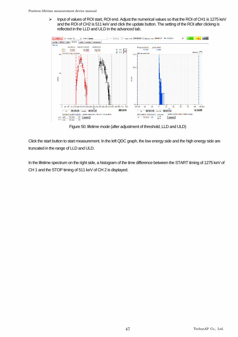
➢ Input of values of ROI start, ROI end. Adjust the numerical values so that the ROI of CH1 is 1275 keV and the ROI of CH2 is 511 keV and click the update button. The setting of the ROI after clicking is reflected in the LLD and ULD in the advanced tab.
Figure 50: lifetime mode (after adjustment of threshold, LLD and ULD)
Click the start button to start measurement. In the left QDC graph, the low energy side and the high energy side are
truncated in the range of LLD and ULD.
In the lifetime spectrum on the right side, a histogram of the time difference between the START timing of 1275 keV of
CH 1 and the STOP timing of 511 keV of CH 2 is displayed.
Positron lifetime measurement device manual
48 TechnoAP Co., Ltd.
5.5.2. The measurement
The measurement is started after completion of the above adjustment.
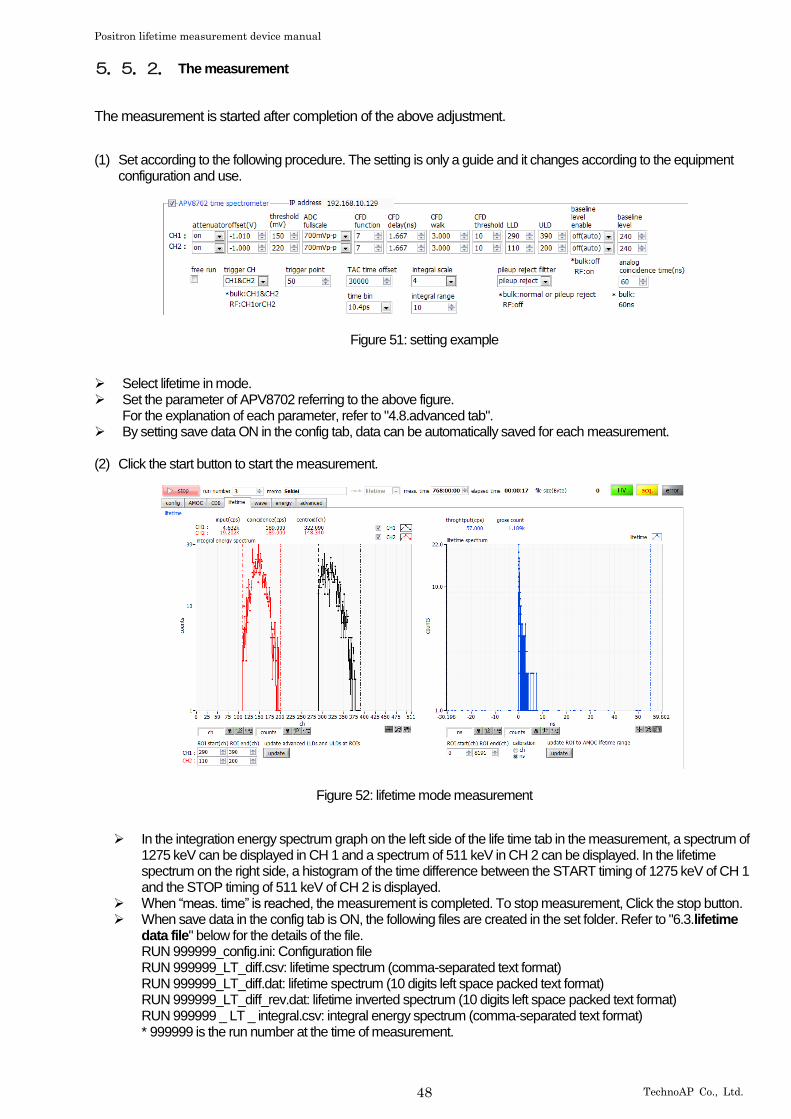
(1) Set according to the following procedure. The setting is only a guide and it changes according to the equipment configuration and use.
Figure 51: setting example
➢ Select lifetime in mode. ➢ Set the parameter of APV8702 referring to the above figure.
For the explanation of each parameter, refer to "4.8.advanced tab". ➢ By setting save data ON in the config tab, data can be automatically saved for each measurement.
(2) Click the start button to start the measurement.
Figure 52: lifetime mode measurement
➢ In the integration energy spectrum graph on the left side of the life time tab in the measurement, a spectrum of 1275 keV can be displayed in CH 1 and a spectrum of 511 keV in CH 2 can be displayed. In the lifetime spectrum on the right side, a histogram of the time difference between the START timing of 1275 keV of CH 1 and the STOP timing of 511 keV of CH 2 is displayed.
➢ When “meas. time” is reached, the measurement is completed. To stop measurement, Click the stop button. ➢ When save data in the config tab is ON, the following files are created in the set folder. Refer to "6.3.lifetime
data file" below for the details of the file. RUN 999999_config.ini: Configuration file RUN 999999_LT_diff.csv: lifetime spectrum (comma-separated text format) RUN 999999_LT_diff.dat: lifetime spectrum (10 digits left space packed text format) RUN 999999_LT_diff_rev.dat: lifetime inverted spectrum (10 digits left space packed text format) RUN 999999 _ LT _ integral.csv: integral energy spectrum (comma-separated text format) * 999999 is the run number at the time of measurement.
Positron lifetime measurement device manual
49 TechnoAP Co., Ltd.
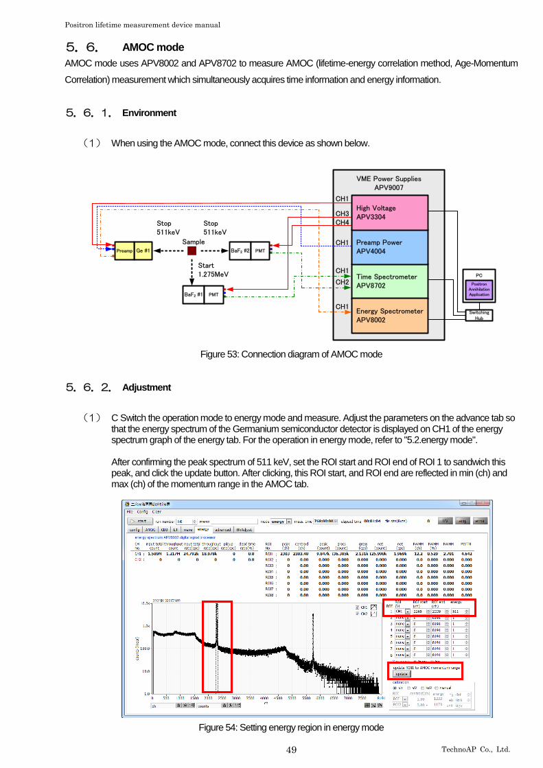
5.6. AMOC mode
AMOC mode uses APV8002 and APV8702 to measure AMOC (lifetime-energy correlation method, Age-Momentum
Correlation) measurement which simultaneously acquires time information and energy information.
5.6.1. Environment
(1) When using the AMOC mode, connect this device as shown below.
VME Power SuppliesAPV9007
BaF2 #2 PMT
BaF2 #1 PMT
Ge #1Preamp
Stop511keV
Stop511keV
Start1.275MeV
Sample
PC Time Spectrometer APV8702
Energy Spectrometer APV8002
Preamp Power APV4004
High Voltage APV3304
SwitchingHub
PositronAnnihilationApplication
CH1
CH3
CH1
CH1
CH4
CH1
CH2
Figure 53: Connection diagram of AMOC mode
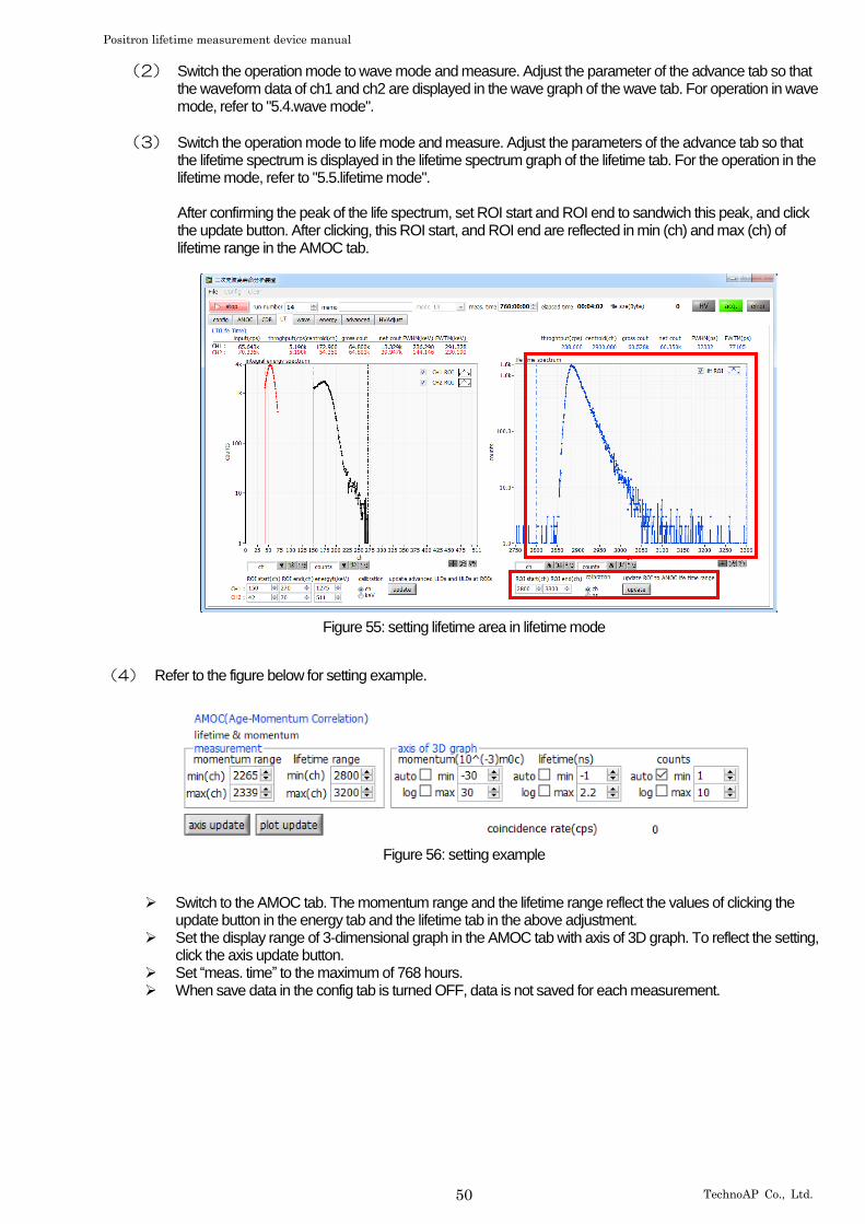
5.6.2. Adjustment
(1) C Switch the operation mode to energy mode and measure. Adjust the parameters on the advance tab so that the energy spectrum of the Germanium semiconductor detector is displayed on CH1 of the energy spectrum graph of the energy tab. For the operation in energy mode, refer to "5.2.energy mode". After confirming the peak spectrum of 511 keV, set the ROI start and ROI end of ROI 1 to sandwich this peak, and click the update button. After clicking, this ROI start, and ROI end are reflected in min (ch) and max (ch) of the momentum range in the AMOC tab.
Figure 54: Setting energy region in energy mode
Positron lifetime measurement device manual
50 TechnoAP Co., Ltd.
(2) Switch the operation mode to wave mode and measure. Adjust the parameter of the advance tab so that the waveform data of ch1 and ch2 are displayed in the wave graph of the wave tab. For operation in wave mode, refer to "5.4.wave mode".
(3) Switch the operation mode to life mode and measure. Adjust the parameters of the advance tab so that the lifetime spectrum is displayed in the lifetime spectrum graph of the lifetime tab. For the operation in the lifetime mode, refer to "5.5.lifetime mode". After confirming the peak of the life spectrum, set ROI start and ROI end to sandwich this peak, and click the update button. After clicking, this ROI start, and ROI end are reflected in min (ch) and max (ch) of lifetime range in the AMOC tab.
Figure 55: setting lifetime area in lifetime mode
(4) Refer to the figure below for setting example.
Figure 56: setting example
➢ Switch to the AMOC tab. The momentum range and the lifetime range reflect the values of clicking the update button in the energy tab and the lifetime tab in the above adjustment.
➢ Set the display range of 3-dimensional graph in the AMOC tab with axis of 3D graph. To reflect the setting, click the axis update button.
➢ Set “meas. time” to the maximum of 768 hours. ➢ When save data in the config tab is turned OFF, data is not saved for each measurement.
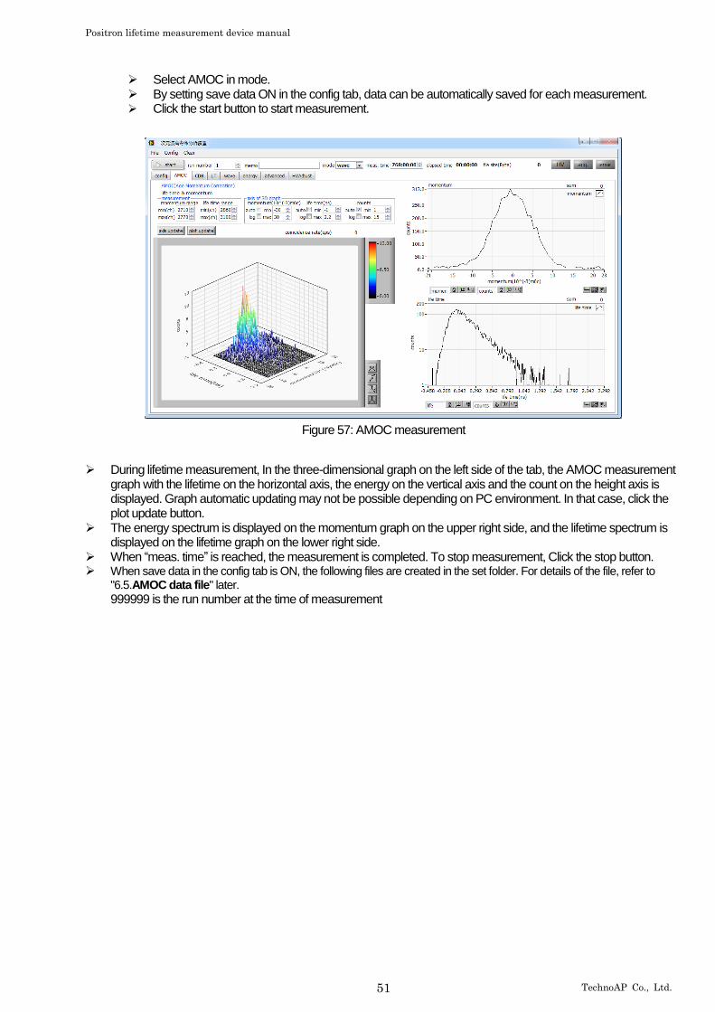
Positron lifetime measurement device manual
51 TechnoAP Co., Ltd.
➢ Select AMOC in mode. ➢ By setting save data ON in the config tab, data can be automatically saved for each measurement. ➢ Click the start button to start measurement.
Figure 57: AMOC measurement
➢ During lifetime measurement, In the three-dimensional graph on the left side of the tab, the AMOC measurement graph with the lifetime on the horizontal axis, the energy on the vertical axis and the count on the height axis is displayed. Graph automatic updating may not be possible depending on PC environment. In that case, click the plot update button.
➢ The energy spectrum is displayed on the momentum graph on the upper right side, and the lifetime spectrum is displayed on the lifetime graph on the lower right side.
➢ When “meas. time” is reached, the measurement is completed. To stop measurement, Click the stop button. ➢ When save data in the config tab is ON, the following files are created in the set folder. For details of the file, refer to
"6.5.AMOC data file" later. 999999 is the run number at the time of measurement

Positron lifetime measurement device manual
52 TechnoAP Co., Ltd.
6. File
6.1. Configuration file
This is the configuration file of this application. The file name is RUN999999_config.ini. It is stored together with data at
the end of each mode measurement. You can reproduce the setting by reading the file from the menu.
Example:
[System] PCConfigPort = 55001 PCStatusPort = 55000 PCDataPort = 55002 DevConfigPort = 5000 DevStatusPort = 5001 DevDataPort = 5002 SubnetMask = "255.255.255.0" Gateway = "192.168.10.1" ChNumber = 2 [3G] Enable = 1 IP = "192.168.10.129" CH1 = "0 0 150 6 0 230 0 0 0 0 7 1.666665 3 10 290 372 0 0 0 0 0 0 150 255 0 -1.01 1 0 60 31 0 0 240" CH2 = "0 0 220 6 0 230 0 0 0 0 7 1.666665 3 10 110 195 0 0 0 0 0 0 220 255 0 -1 1 0 60 31 0 0 240" Mode = 0 WaveTrigCH = 3 WaveTrigMode = 0 ADCBufSize = 0 ADCReadSize = 1 TrigPoint = 50 CalcFIFOIRQTrig = 200 CalcDiscriMode = 0 TimeOffset = 30000 TimeBin = 3 IntegralScale = 2 IntegralRange = 10 CoinGateTime = 3 PileupRejectFilter = 1 ForRF = 1 [DSP] Enable = 1 IP = "192.168.10.128" CH1 = "1 0 3 4 6000 700 0 676 10 30 8100 20 0 0 4 0.5000 1 0 3 60" CH2 = "1 0 3 4 6000 700 0 676 10 30 8100 20 0 0 4 0.5000 1 0 3 60" CH3 = "3 0 4 4 6000 700 0 680 30 30 8190 30 0 1 5 0.5000 1 0 0 40" CH4 = "3 0 4 4 6000 700 0 672 30 30 8190 30 0 1 5 0.5000 1 0 0 40" CH5 = "3 0 4 4 6000 700 0 680 30 30 8190 30 0 1 5 0.5000 1 0 0 40" CH6 = "3 0 4 4 6000 700 0 680 30 30 8190 30 0 1 5 0.5000 1 0 0 40" CH7 = "3 0 4 4 6000 700 0 680 30 30 8190 30 0 1 5 0.5000 1 0 0 40" CH8 = "3 0 4 4 6000 700 0 680 30 30 8190 30 0 1 5 0.5000 1 0 0 40" MOD = 0 MMD = 0 MTM = 2764800 CLS = 0 DAC = 0 CCH = 0 CTM = 100 CGT = 8000 CDL = "0 0 0 0" FRC = 100 LTL = 1000 CMR = 2 CMO = "0 0" ACT = 1000 ACD = 2800 [HV] Model = "APV3304" Enable = 1 IP = "192.168.10.130" Port = 10001 CH = 4 HV1 = "+5kV 2000 500 8192 8192 8176 8439 8120 8162 0 -24 6000" HV2 = "+5kV 0 500 8192 8192 8197 8371 8192 8102 0 -24 6000" HV3 = "-4kV 3000 4000 8232 8192 8240 8253 8156 8080 0 -24 4000" HV4 = "-4kV 3000 4000 8232 8192 8240 8249 8080 8089 0 -24 4000" [Config] RunNumber = 5 Memo = "SUS" Mode = 3 MeasTime (s) = 2764800 SaveData = 1 SaveFolder = "/C/Data/180510_KUR_Sekiei" ListSave = 1 ListPath = "/C/Temp/list_.bin" ListFileNum = 16 ListFileSize (Byte) = 100000000 AutoSave = 1 IntervalTime (s) = 3600
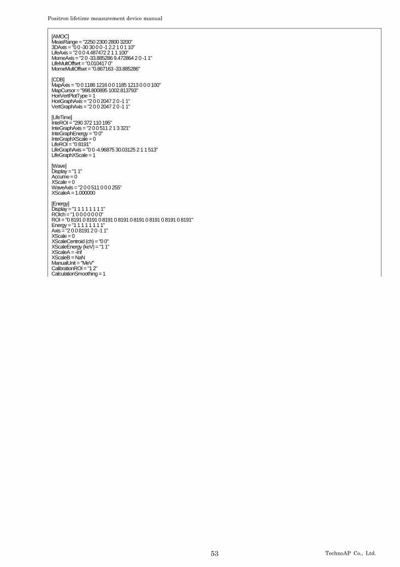
Positron lifetime measurement device manual
53 TechnoAP Co., Ltd.
[AMOC] MeasRange = "2250 2300 2800 3200" 3DAxis = "0 0 -30 30 0 0 -1 2.2 1 0 1 10" LifeAxis = "2 0 0 4.487472 2 1 1 100" MomeAxis = "2 0 -33.885286 9.472864 2 0 -1 1" LifeMultOffset = "0.010417 0" MomeMultOffset = "0.867163 -33.885286" [CDB] MapAxis = "0 0 1186 1216 0 0 1185 1213 0 0 0 100" MapCursor = "998.800895 1002.813793" HoriVertPlotType = 1 HoriGraphAxis = "2 0 0 2047 2 0 -1 1" VertGraphAxis = "2 0 0 2047 2 0 -1 1" [LifeTime] InteROI = "290 372 110 195" InteGraphAxis = "2 0 0 511 2 1 3 321" InteGraphEnergy = "0 0" InteGraphXScale = 0 LifeROI = "0 8191" LifeGraphAxis = "0 0 -4.96875 30.03125 2 1 1 513" LifeGraphXScale = 1 [Wave] Display = "1 1" Accume = 0 XScale = 0 WaveAxis = "2 0 0 511 0 0 0 255" XScaleA = 1.000000 [Energy] Display = "1 1 1 1 1 1 1 1" ROIch = "1 0 0 0 0 0 0 0" ROI = "0 8191 0 8191 0 8191 0 8191 0 8191 0 8191 0 8191 0 8191" Energy = "1 1 1 1 1 1 1 1" Axis = "2 0 0 8191 2 0 -1 1" XScale = 0 XScaleCentroid (ch) = "0 0" XScaleEnergy (keV) = "1 1" XScaleA = -Inf XScaleB = NaN ManualUnit = "MeV" CalibrationROI = "1 2" CalculationSmoothing = 1

Positron lifetime measurement device manual
54 TechnoAP Co., Ltd.
6.2. energy data file
It is data of energy mode. Energy spectrum data, calculation result between status and ROI, and the like are stored. A
comma-separated text format file. The file name is RU999999_spectrum.csv.
Example:
[Header] Measurement mode, Real Time Measurement time,2764800 Real time,39 Live time,36 Dead time,3 Start Time,15/12/21 17:47:45 End Time,15/12/21 17:48:55 //CH#,ACG,ADG,FIT,FDI,SFR(ns),SFP(ns),FPZ,SPZ,FTH,LLD,ULD,STH,PUR,POL,DCG,DFG,TMS,CFF,CFD,IHW,PZD,FGD,DIF,BRS,BTS CH1,2,0,3,3,6000,700,0,680,10,30,8100,20,0,0,5,0.632033,1,0,3,60 CH2,2,0,3,3,6000,700,0,680,10,30,8100,20,0,0,5,0.708600,1,0,3,60 CH3,2,1,4,4,6000,700,0,680,30,30,8190,30,0,1,5,0.500000,1,0,0,40 CH4,2,1,4,4,6000,700,0,672,30,30,8190,30,0,1,5,0.500000,1,0,0,40 CH5,2,1,4,4,6000,700,0,680,30,30,8190,30,0,1,5,0.500000,1,0,0,40 CH6,2,1,4,4,6000,700,0,680,30,30,8190,30,0,1,5,0.500000,1,0,0,40 CH7,2,1,4,4,6000,700,0,680,30,30,8190,30,0,1,5,0.500000,1,0,0,40 CH8,2,1,4,4,6000,700,0,680,30,30,8190,30,0,1,5,0.500000,1,0,0,40 MOD,0 MMD,0 MTM,2764800 CLS,0 [Calculation] //ROI_CH,ROI_start,ROI_end,Energy,peak (ch) ,centroid (ch) ,peak (count) ,gross (count) ,gross (cps) ,net (count) ,net (cps) ,FWHM (ch) ,FWHM (%) ,FWHM,FWTM CH1,1990,2095,1173,2036,2036.16,2556,34452,883.385,33082.486,848.269,11.291,0.555,6.505,13.56 CH1,5027,5143,1333,5082,5081.96,1163,9194,235.744,9086.362,232.984,7.125,0.14,1.869,3.543 CH0,0,0,0,0,0,0,0,0,0,0,0,0,0,0 CH0,4614,5344,511,0,0,0,0,0,0,0,0,0,0,0 CH0,5958,6032,1274,0,0,0,0,0,0,0,0,0,0,0 CH0,0,8191,1,0,0,0,0,0,0,0,0,0,0,0 CH0,0,8191,1,0,0,0,0,0,0,0,0,0,0,0 CH0,0,8191,1,0,0,0,0,0,0,0,0,0,0,0 [Status] //CH, input total count,throughput count,input total rate (cps) ,throughput rate (cps) ,pileup rate (cps) ,dead time ratio (%) CH1,241307,224267,6153,5739,0,8.2 CH2,0,0,0,0,0,0 CH3,0,0,0,0,0,0 CH4,0,0,0,0,0,0 CH5,0,0,0,0,0,0 CH6,0,0,0,0,0,0 CH7,0,0,0,0,0,0 CH8,0,0,0,0,0,0 [Data] ch,CH1,CH2 0,0,0 1,0,0 2,0,0 3,0,0 4,0,0 5,0,0 6,0,0 7,0,0 8,0,0 9,0,0 10,0,0 11,0,0 12,0,0 13,0,0 14,0,0 15,0,0 16,0,0 17,0,0 18,0,0 19,0,0 20,0,0 21,0,0 22,0,0 23,0,0 24,0,0 25,0,0 26,0,0 27,0,0 28,0,0 29,0,0 30,0,0 31,55,0 32,67,0 33,60,0 34,74,0 35,56,0 : ※ For 8192ch
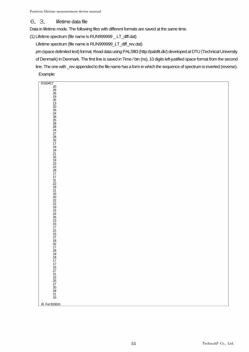
Positron lifetime measurement device manual
55 TechnoAP Co., Ltd.
6.3. lifetime data file
Data in lifetime mode. The following files with different formats are saved at the same time.
(1) Lifetime spectrum (file name is RUN999999 _ LT_diff.dat)
Lifetime spectrum (file name is RUN999999_LT_diff_rev.dat)
prn (space delimited text) format. Read data using PALSfit3 (http://palsfit.dk/) developed at DTU (Technical University
of Denmark) in Denmark. The first line is saved in Time / bin (ns), 10 digits left-justified space format from the second
line. The one with _rev appended to the file name has a form in which the sequence of spectrum is inverted (reverse).
Example:
0.010417 20 29 26 19 25 13 20 26 24 28 25 28 28 24 27 28 32 17 19 19 21 32 19 23 22 29 17 17 31 22 18 21 16 20 22 22 19 15 24 26 23 15 17 22 15 27 18 32 17 28 19 18 17 17 15 27 21 15 25 27 20 28 21 15 : ※ For 8192ch
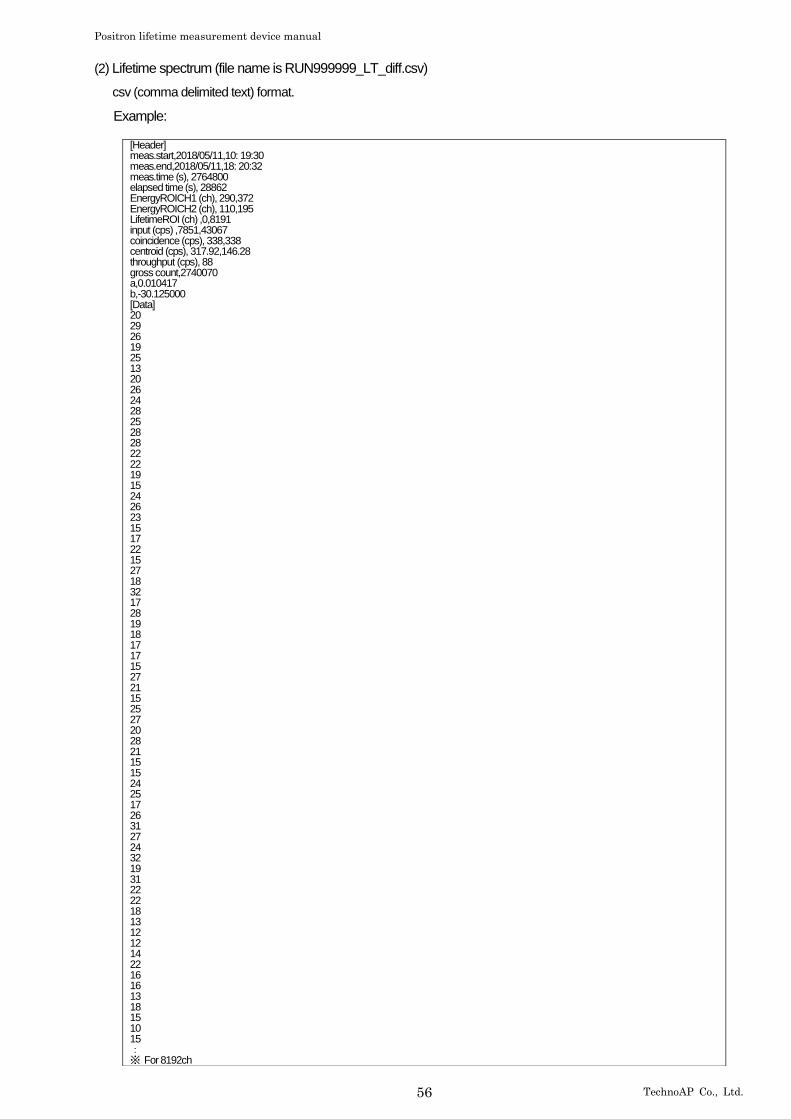
Positron lifetime measurement device manual
56 TechnoAP Co., Ltd.
(2) Lifetime spectrum (file name is RUN999999_LT_diff.csv)
csv (comma delimited text) format.
Example:
[Header] meas.start,2018/05/11,10: 19:30 meas.end,2018/05/11,18: 20:32 meas.time (s), 2764800 elapsed time (s), 28862 EnergyROICH1 (ch), 290,372 EnergyROICH2 (ch), 110,195 LifetimeROI (ch) ,0,8191 input (cps) ,7851,43067 coincidence (cps), 338,338 centroid (cps), 317.92,146.28 throughput (cps), 88 gross count,2740070 a,0.010417 b,-30.125000 [Data] 20 29 26 19 25 13 20 26 24 28 25 28 28 22 22 19 15 24 26 23 15 17 22 15 27 18 32 17 28 19 18 17 17 15 27 21 15 25 27 20 28 21 15 15 24 25 17 26 31 27 24 32 19 31 22 22 18 13 12 12 14 22 16 16 13 18 15 10 15 : ※ For 8192ch
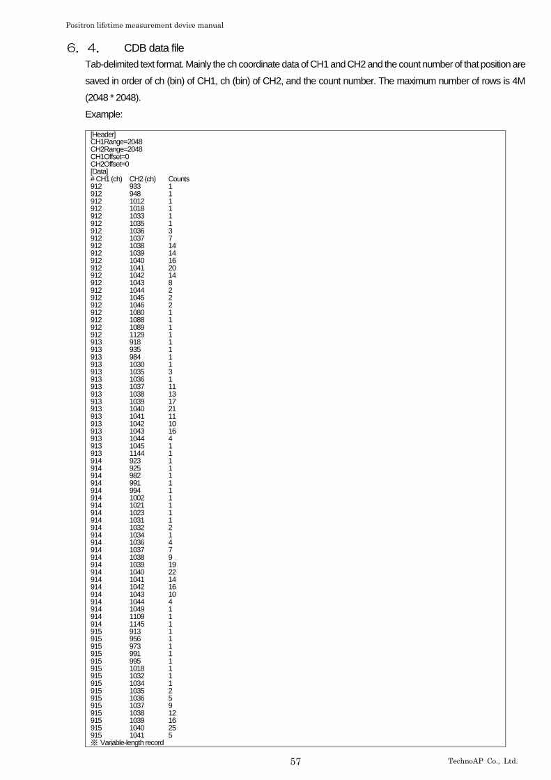
Positron lifetime measurement device manual
57 TechnoAP Co., Ltd.
6.4. CDB data file
Tab-delimited text format. Mainly the ch coordinate data of CH1 and CH2 and the count number of that position are
saved in order of ch (bin) of CH1, ch (bin) of CH2, and the count number. The maximum number of rows is 4M
(2048 * 2048).
Example:
[Header] CH1Range=2048 CH2Range=2048 CH1Offset=0 CH2Offset=0 [Data] # CH1 (ch) CH2 (ch) Counts 912 933 1 912 948 1 912 1012 1 912 1018 1 912 1033 1 912 1035 1 912 1036 3 912 1037 7 912 1038 14 912 1039 14 912 1040 16 912 1041 20 912 1042 14 912 1043 8 912 1044 2 912 1045 2 912 1046 2 912 1080 1 912 1088 1 912 1089 1 912 1129 1 913 918 1 913 935 1 913 984 1 913 1030 1 913 1035 3 913 1036 1 913 1037 11 913 1038 13 913 1039 17 913 1040 21 913 1041 11 913 1042 10 913 1043 16 913 1044 4 913 1045 1 913 1144 1 914 923 1 914 925 1 914 982 1 914 991 1 914 994 1 914 1002 1 914 1021 1 914 1023 1 914 1031 1 914 1032 2 914 1034 1 914 1036 4 914 1037 7 914 1038 9 914 1039 19 914 1040 22 914 1041 14 914 1042 16 914 1043 10 914 1044 4 914 1049 1 914 1109 1 914 1145 1 915 913 1 915 956 1 915 973 1 915 991 1 915 995 1 915 1018 1 915 1032 1 915 1034 1 915 1035 2 915 1036 5 915 1037 9 915 1038 12 915 1039 16 915 1040 25 915 1041 5 ※ Variable-length record
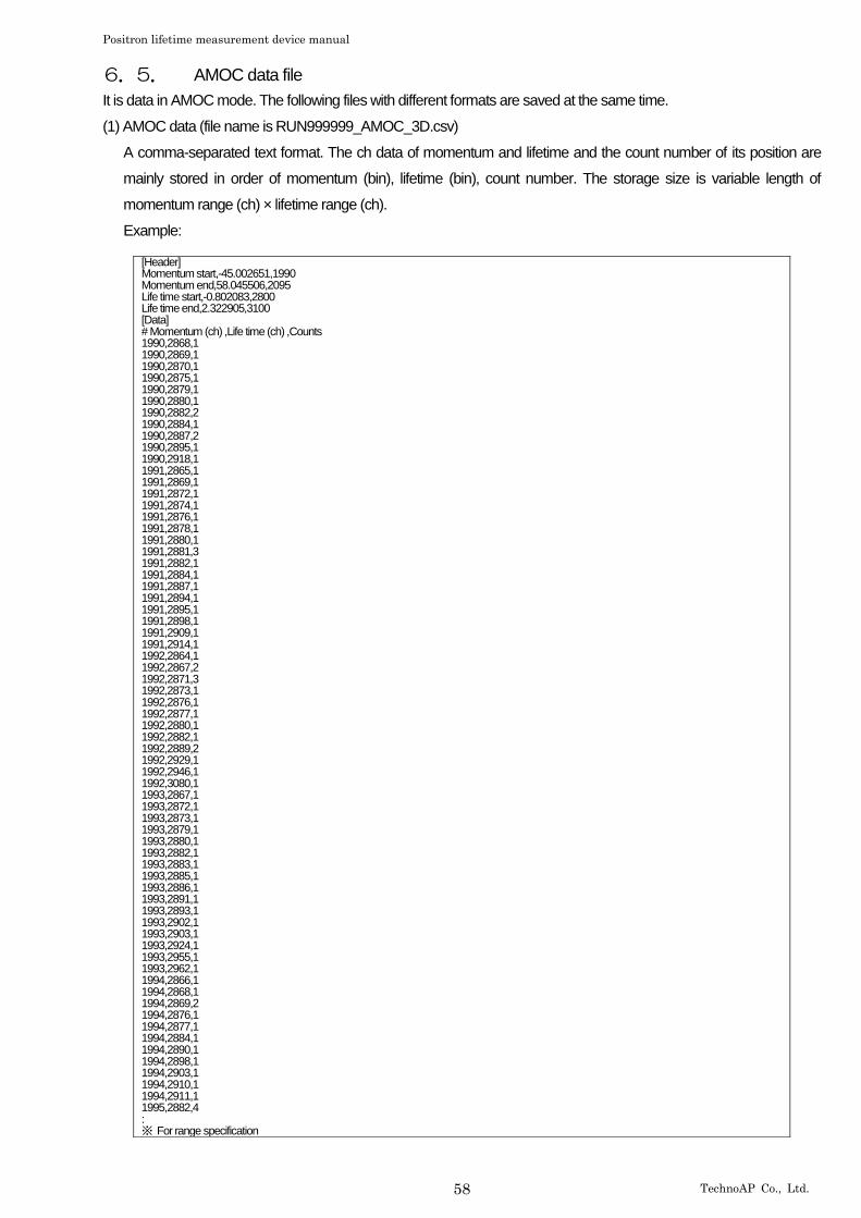
Positron lifetime measurement device manual
58 TechnoAP Co., Ltd.
6.5. AMOC data file
It is data in AMOC mode. The following files with different formats are saved at the same time.
(1) AMOC data (file name is RUN999999_AMOC_3D.csv)
A comma-separated text format. The ch data of momentum and lifetime and the count number of its position are
mainly stored in order of momentum (bin), lifetime (bin), count number. The storage size is variable length of
momentum range (ch) × lifetime range (ch).
Example:
[Header] Momentum start,-45.002651,1990 Momentum end,58.045506,2095 Life time start,-0.802083,2800 Life time end,2.322905,3100 [Data] # Momentum (ch) ,Life time (ch) ,Counts 1990,2868,1 1990,2869,1 1990,2870,1 1990,2875,1 1990,2879,1 1990,2880,1 1990,2882,2 1990,2884,1 1990,2887,2 1990,2895,1 1990,2918,1 1991,2865,1 1991,2869,1 1991,2872,1 1991,2874,1 1991,2876,1 1991,2878,1 1991,2880,1 1991,2881,3 1991,2882,1 1991,2884,1 1991,2887,1 1991,2894,1 1991,2895,1 1991,2898,1 1991,2909,1 1991,2914,1 1992,2864,1 1992,2867,2 1992,2871,3 1992,2873,1 1992,2876,1 1992,2877,1 1992,2880,1 1992,2882,1 1992,2889,2 1992,2929,1 1992,2946,1 1992,3080,1 1993,2867,1 1993,2872,1 1993,2873,1 1993,2879,1 1993,2880,1 1993,2882,1 1993,2883,1 1993,2885,1 1993,2886,1 1993,2891,1 1993,2893,1 1993,2902,1 1993,2903,1 1993,2924,1 1993,2955,1 1993,2962,1 1994,2866,1 1994,2868,1 1994,2869,2 1994,2876,1 1994,2877,1 1994,2884,1 1994,2890,1 1994,2898,1 1994,2903,1 1994,2910,1 1994,2911,1 1995,2882,4 : ※ For range specification
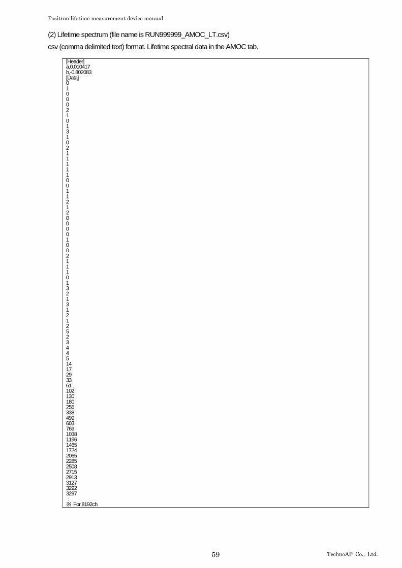
Positron lifetime measurement device manual
59 TechnoAP Co., Ltd.
(2) Lifetime spectrum (file name is RUN999999_AMOC_LT.csv)
csv (comma delimited text) format. Lifetime spectral data in the AMOC tab.
[Header] a,0.010417 b,-0.802083 [Data] 0 1 0 0 0 2 1 0 1 3 1 0 2 1 1 1 1 1 0 0 1 1 2 1 2 0 0 0 0 1 0 0 2 1 1 1 0 1 3 2 1 3 1 2 1 2 5 2 3 4 4 5 14 17 29 33 61 102 130 180 256 338 499 603 769 1038 1196 1465 1724 2065 2285 2508 2715 2913 3127 3292 3297 : ※ For 8192ch
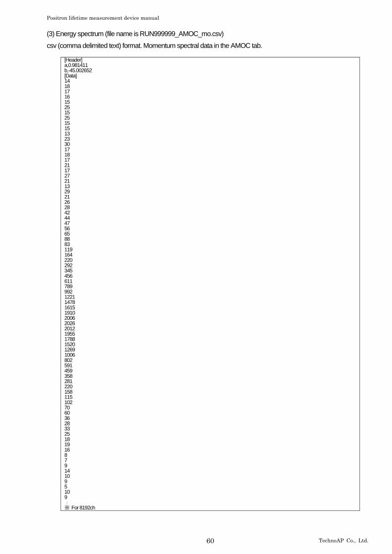
Positron lifetime measurement device manual
60 TechnoAP Co., Ltd.
(3) Energy spectrum (file name is RUN999999_AMOC_mo.csv)
csv (comma delimited text) format. Momentum spectral data in the AMOC tab.
[Header] a,0.981411 b,-45.002652 [Data] 14 18 17 16 15 25 15 25 15 15 13 23 30 17 18 17 21 17 27 21 13 29 21 26 28 42 44 47 56 65 88 83 119 164 220 292 345 456 611 789 992 1221 1478 1615 1910 2006 2026 2012 1955 1788 1520 1269 1006 802 591 459 358 281 220 158 115 102 70 60 36 28 33 25 18 19 16 8 7 9 14 10 9 5 10 9 : ※ For 8192ch
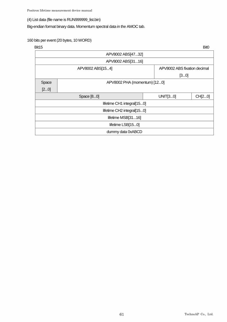
Positron lifetime measurement device manual
61 TechnoAP Co., Ltd.
(4) List data (file name is RUN999999_list.bin)
Big-endian format binary data. Momentum spectral data in the AMOC tab.
160 bits per event (20 bytes, 10 WORD)
Bit15 Bit0
APV8002 ABS[47...32]
APV8002 ABS[31...16]
APV8002 ABS[15...4] APV8002 ABS fixation decimal
[3...0]
Space
[2...0]
APV8002 PHA (momentum) [12...0]
Space [8...0] UNIT[3...0] CH[2...0]
lifetime CH1 integral[15...0]
lifetime CH2 integral[15...0]
lifetime MSB[31...16]
lifetime LSB[15...0]
dummy data 0xABCD

Positron lifetime measurement device manual
62 TechnoAP Co., Ltd.
6.6. wave data file
csv (comma delimited text) format. 512 waveform data of 16 times of CH1 and CH2 are saved.
Example:
ch,CH1 (digit) ,CH2 (digit) ,CH1-1,CH1-2,CH1-3,CH1-4,CH1-5,CH1-6,CH1-7,CH1-8,CH1-9,CH1-10,CH1-11,CH1-12,CH1-13,CH1-14,CH1-15,CH1-16,CH2-1,CH2-2,CH2-3,CH2-4,CH2-5,CH2-6,CH2-7,CH2-8,CH2-9,CH2-10,CH2-11,CH2-12,CH2-13,CH2-14,CH2-15,CH2-16 0,239,240,239,239,239,240,239,239,239,239,239,239,238,239,239,239,239,239,240,241,240,241,240,240,240,240,240,240,240,240,240,241,240,240 1,240,240,240,240,239,241,239,239,240,241,239,240,239,239,240,240,239,239,240,239,240,241,240,241,240,240,239,240,239,240,239,240,240,238 2,240,241,240,240,239,239,239,238,238,239,240,239,239,239,239,240,239,239,241,240,240,240,240,241,240,240,240,240,240,240,239,241,241,240 3,241,241,241,240,239,240,239,240,238,240,240,240,239,239,239,241,239,240,241,241,240,239,239,240,239,239,240,240,241,240,240,241,241,240 4,239,240,239,239,238,240,239,240,239,239,239,239,238,238,239,239,239,239,240,241,240,240,240,240,241,240,240,240,240,241,240,240,240,240 5,240,240,240,240,239,240,239,239,240,241,239,240,240,239,240,240,239,239,240,240,239,240,240,241,241,240,239,240,239,240,240,240,240,239 6,240,240,240,239,239,239,239,239,238,239,239,239,239,239,239,239,239,239,240,240,239,240,240,240,240,240,240,240,240,240,240,241,239,239 7,241,241,241,241,239,240,239,239,239,239,240,240,240,239,240,241,239,240,241,241,240,240,239,240,240,240,240,240,241,240,240,241,240,241 8,239,240,239,239,238,240,239,239,239,239,239,239,238,239,239,239,239,239,240,240,240,240,239,240,240,240,240,240,240,241,240,240,240,240 9,240,240,240,239,239,241,240,241,239,240,239,239,238,239,240,239,239,239,240,239,240,240,240,240,241,240,239,240,239,240,240,240,240,239 10,239,240,239,240,239,239,240,239,238,239,239,239,239,238,239,239,239,239,240,241,240,241,241,240,240,240,240,241,240,240,240,241,239,240 11,240,240,240,241,240,239,239,239,239,240,240,240,239,239,240,240,238,240,240,241,240,240,240,240,240,240,241,241,241,240,240,241,240,240 12,239,240,239,239,239,240,239,239,239,239,240,238,238,239,239,239,239,239,240,240,240,240,240,241,240,240,240,240,240,240,240,240,240,240 13,240,240,240,239,238,241,240,239,239,239,239,239,239,239,239,240,239,238,240,239,240,240,240,240,241,240,239,240,240,239,239,240,239,239 14,240,241,240,240,239,239,239,239,239,239,239,240,239,238,239,240,239,239,241,240,240,241,241,240,240,240,241,240,241,239,239,241,239,240 15,240,240,240,241,240,239,239,239,240,240,241,240,239,239,240,240,239,240,240,241,240,240,240,240,240,240,241,241,240,240,240,241,240,240 16,239,240,239,239,239,240,239,240,239,239,240,238,238,239,239,239,238,238,240,240,240,240,240,241,240,240,241,240,239,240,240,240,240,240 17,239,240,239,239,238,240,240,239,240,240,239,240,239,239,240,239,239,239,240,240,240,240,241,240,240,240,239,240,240,240,240,241,240,239 18,240,241,240,240,240,239,239,239,239,239,239,240,239,238,239,240,239,239,241,240,239,241,241,240,241,240,240,240,240,240,240,240,240,240 19,241,240,241,241,240,240,239,240,239,240,241,240,239,239,240,241,240,239,240,241,240,240,240,240,240,240,240,240,240,240,240,241,240,240 20,239,240,239,238,238,240,239,239,239,240,240,239,238,239,239,239,239,238,240,241,240,240,240,240,240,241,241,240,240,240,239,240,240,240 21,239,239,239,239,238,241,239,240,240,241,240,240,239,239,240,239,239,239,239,240,240,240,240,240,240,240,240,240,240,239,239,239,240,240 22,240,240,240,240,239,239,238,238,239,239,240,239,239,239,240,239,239,239,240,240,239,240,241,240,241,240,241,241,240,239,240,240,240,240 23,241,241,241,241,239,240,239,239,239,240,241,240,239,240,240,241,239,240,241,241,240,240,240,240,240,240,240,240,240,240,239,241,241,240 24,239,240,239,239,238,240,239,239,239,239,239,238,238,239,239,238,239,238,240,241,240,240,240,241,240,241,240,240,240,240,238,240,240,240 25,240,240,240,239,239,241,239,239,239,241,239,239,239,239,240,239,240,239,240,240,240,240,240,241,240,240,240,240,240,240,238,240,239,240 26,239,240,239,239,240,239,238,238,239,239,239,239,238,238,240,240,239,239,240,240,241,240,240,240,241,240,241,240,240,240,239,240,240,241 27,240,240,240,240,239,240,239,239,239,240,241,240,239,239,241,240,240,240,240,241,240,240,240,240,239,240,240,241,240,240,238,240,241,240 28,239,240,239,239,238,239,240,239,239,239,239,238,239,239,239,239,239,238,240,240,239,240,240,241,240,240,240,240,240,241,239,239,240,240 29,239,239,239,240,239,240,239,240,239,240,240,239,239,239,239,239,239,239,239,240,239,240,241,241,240,240,240,240,240,240,239,239,240,240 30,239,240,239,240,239,239,238,239,239,240,239,239,239,239,239,240,239,239,240,239,240,240,240,240,240,240,241,240,240,241,239,240,240,240 31,240,240,240,241,240,240,239,239,239,240,239,241,240,240,239,240,239,240,240,240,240,240,240,240,240,240,240,240,240,241,240,240,241,240 32,239,240,239,239,238,239,239,239,239,239,239,239,239,239,239,239,239,239,240,239,240,240,240,240,240,240,241,240,240,240,240,240,240,240 33,239,240,239,240,238,240,239,240,239,241,240,240,239,240,239,239,239,239,240,240,239,240,240,240,240,240,240,240,239,240,239,240,240,240 34,239,241,239,240,239,239,239,239,239,239,239,240,239,239,240,239,239,239,241,240,240,240,240,240,241,240,241,240,241,239,239,239,240,240 35,241,240,241,241,240,240,239,239,239,240,240,240,240,240,241,241,239,240,240,239,240,239,240,240,240,239,241,240,241,240,239,240,240,241 36,239,240,239,239,239,240,239,239,239,240,239,238,238,239,239,239,239,238,240,234,239,240,240,240,241,240,240,240,240,240,240,240,240,241 37,239,240,239,240,238,240,240,240,240,241,240,240,238,239,239,238,239,239,240,225,239,241,240,241,240,240,240,239,240,238,238,240,240,240 38,239,240,239,240,239,239,239,239,239,239,239,239,239,239,240,239,239,238,240,203,240,240,240,240,240,241,241,240,241,240,239,239,240,240 39,241,240,241,241,239,240,239,239,239,239,240,240,240,240,241,240,240,239,240,162,240,239,240,240,238,240,241,240,240,240,239,240,241,240 40,239,240,239,239,239,240,239,239,239,240,239,239,239,239,239,239,239,238,240,108,240,240,240,239,241,239,240,239,240,241,240,240,241,241 41,240,239,240,240,239,240,238,240,240,241,239,240,238,239,239,239,240,239,239,57,239,241,240,241,240,240,239,236,240,239,240,240,239,240 42,239,240,239,240,238,239,239,238,239,239,240,239,238,239,240,239,239,239,240,25,240,240,240,241,240,241,240,230,240,241,239,239,240,240 43,241,240,241,241,239,239,239,239,239,239,240,240,239,240,240,240,240,239,240,21,240,236,240,240,239,240,239,219,241,241,239,238,240,240 44,239,240,239,239,238,238,239,240,239,239,239,238,238,239,239,238,239,238,240,42,240,232,241,240,241,239,235,204,240,241,239,233,238,240 45,239,240,239,239,238,238,239,240,238,239,238,238,236,239,239,238,239,239,240,65,239,222,240,240,241,237,230,187,239,239,232,225,233,239 46,239,240,239,236,238,236,236,238,237,238,236,236,233,238,238,235,236,239,240,86,240,205,239,240,240,229,220,179,238,239,221,213,226,240 47,239,240,239,231,238,232,234,237,234,235,229,233,227,236,235,227,232,238,240,105,239,183,239,240,237,217,208,180,233,238,198,199,216,240 48,234,240,234,223,233,224,230,232,225,228,217,227,216,229,230,214,224,234,240,129,237,169,240,239,234,205,197,186,226,233,160,190,205,239 49,227,239,227,214,224,215,224,220,206,214,201,221,207,221,224,199,214,227,239,149,232,164,240,237,223,195,193,190,217,225,116,190,200,235 50,218,240,218,204,209,209,216,198,173,197,184,218,203,209,216,187,205,210,240,164,226,169,239,233,208,194,195,194,211,213,84,195,201,229 51,206,239,206,198,185,208,209,172,135,182,173,218,201,197,212,180,200,184,239,173,216,176,239,227,189,196,199,199,209,201,74,201,204,214 52,195,236,195,195,160,209,206,146,100,174,168,218,199,188,209,177,199,153,236,183,209,180,240,218,178,201,203,204,212,193,88,204,205,190 53,189,229,189,195,140,211,203,127,79,174,171,219,201,183,210,181,200,127,229,192,206,184,240,210,178,205,210,209,216,191,109,209,207,161 54,188,220,188,197,133,212,203,119,74,178,178,220,203,183,212,185,203,113,220,200,207,191,241,207,186,209,214,212,221,195,125,214,209,138 55,186,202,186,199,136,213,205,121,83,182,186,224,207,185,216,191,207,111,202,208,210,198,239,209,196,214,217,215,222,197,138,218,211,127 56,186,182,186,201,148,216,208,130,101,187,193,224,210,187,217,197,211,118,182,212,211,205,240,214,204,220,218,218,223,201,151,220,214,127 57,192,168,192,206,160,218,212,142,119,193,201,226,215,191,220,204,215,127,168,215,212,211,240,217,207,223,219,222,224,204,165,223,217,134 58,200,168,200,210,171,219,217,154,135,199,207,229,219,196,221,209,220,137,168,219,215,214,241,217,209,223,221,225,225,208,176,224,221,147 59,204,176,204,215,180,223,220,168,147,206,212,232,222,201,223,213,223,151,176,223,217,218,239,218,212,223,223,227,227,212,181,227,222,162 60,207,185,207,218,186,225,223,180,158,210,215,232,223,206,224,216,225,164,185,224,220,220,240,220,216,224,226,229,229,216,185,227,225,179 61,210,191,210,223,192,228,225,187,169,213,217,232,225,210,226,220,228,177,191,225,221,220,240,222,220,226,228,231,230,217,190,228,228,190 62,213,195,213,224,196,229,227,193,178,215,220,233,227,213,228,223,230,184,195,227,224,223,240,224,223,228,230,233,230,219,197,231,230,197 63,218,198,218,227,201,231,228,200,188,218,223,235,230,216,230,225,231,191,198,228,225,226,239,226,224,232,231,232,230,220,205,234,231,203 64,221,203,221,226,202,233,231,205,195,221,225,235,231,218,231,225,231,199,203,228,225,227,240,228,227,234,233,232,231,222,210,235,234,207 65,224,209,224,229,206,234,233,206,200,224,228,235,232,220,234,228,232,206,209,228,226,230,240,229,229,235,233,233,232,225,214,235,235,212 66,227,214,227,230,210,234,232,209,207,226,230,236,234,223,235,230,232,211,214,227,227,230,240,230,231,235,234,234,236,228,217,235,235,214 67,229,218,229,232,213,235,233,213,212,229,231,238,236,225,235,231,233,215,218,229,228,231,239,232,232,236,235,237,236,230,220,235,234,217 68,230,222,230,232,215,235,234,217,216,229,231,235,235,225,235,231,234,218,222,229,230,232,239,234,233,239,236,237,237,231,220,235,234,220 69,233,224,233,233,218,235,235,222,219,230,233,237,236,228,237,233,235,221,224,230,232,233,240,235,234,238,236,237,237,233,222,236,235,223 70,234,226,234,233,221,234,236,222,220,230,233,236,236,228,237,233,235,224,226,232,233,233,240,236,236,236,237,238,237,234,224,236,235,226 71,234,228,234,233,223,235,236,224,222,230,233,238,238,230,238,235,236,226,228,231,234,233,239,236,236,236,238,238,238,233,226,237,235,228 72,234,230,234,233,223,235,237,227,224,231,232,237,236,230,236,234,236,225,230,231,234,233,239,237,235,237,238,238,238,232,228,237,235,229 73,236,233,236,234,224,237,237,228,225,232,232,238,237,231,238,234,237,227,233,231,235,233,240,238,237,237,236,237,238,233,230,236,237,230 74,234,234,234,235,226,235,237,228,225,232,232,238,236,232,238,234,236,228,234,230,237,233,240,237,237,237,237,238,239,235,232,237,237,232 75,235,235,235,237,226,236,237,230,226,233,233,239,236,233,239,235,237,231,235,229,236,233,240,237,236,236,238,238,238,237,232,239,236,232 76,234,236,234,236,226,236,237,230,226,233,232,237,236,233,238,234,238,231,236,227,236,234,240,238,237,237,238,237,236,237,231,239,236,233 77,236,236,236,237,227,238,239,231,227,234,233,237,237,235,238,235,238,232,236,223,236,234,240,239,237,238,238,235,236,237,231,238,238,233 78,234,237,234,237,228,237,238,230,227,234,233,237,236,234,238,236,237,232,237,221,235,233,240,239,237,238,237,235,237,237,233,238,239,234 79,236,237,236,238,230,239,238,232,228,236,233,237,236,234,238,236,238,231,237,220,236,232,240,238,237,238,238,235,238,237,233,238,238,235 80,234,239,234,236,230,238,239,231,227,236,233,236,234,236,237,235,238,231,239,224,238,233,240,239,237,238,237,233,239,237,232,238,238,235 : For 512 points

Positron lifetime measurement device manual
63 TechnoAP Co., Ltd.
7. Troubleshooting
7.1. Communication error
(1) "connection error" occurs
At startup or when an error occurs in the menu "config", there is a possibility that the network is not connected
properly.
Figure 58: Device connection error at startup
Check the following points.
① Each port number in the [System] section in config.ini of the configuration file before startup is defined as shown below, and "IP" of each device is correctly described. For example, "192.168.10.128" for DSP. Also start this application and confirm that the display of "IP Address" of the DSP in the advanced tab is the same.
[System] PCConfigPort = 55000 PCStatusPort = 55001 PCDataPort = 55002 DevConfigPort = 5000 DevStatusPort = 5001 DevDataPort = 5002 SubnetMask = "255.255.255.0" Gateway = "192.168.10.1" ChNumber = 2
② Confirm whether it is the setting that the network information of the PC can connect to DSP. The default values of the DSP are as follows.
IP address
192.168.10.128 (APV8002)
192.168.10.129 (APV8702)
192.168.10.130 (APV3304)
Subnet mask 255.255.255.0
Gateway (default) 192.168.10.1
Turn on the power supply while the Ethernet cable is connected. Execute the ping command at the command prompt and check the connection between each module and the PC. Turn on the power of each module again and execute the ping command again.
③ Turn off virus detection software and fire fall software.
④ Set the power saving function of the PC to "always ON". Sweep function etc are all turned OFF.
⑤ In the case of notebook PC etc., disable the wireless LAN function.
⑥ Set not to automatically operate Windows update or restart and make the Internet unconnected.
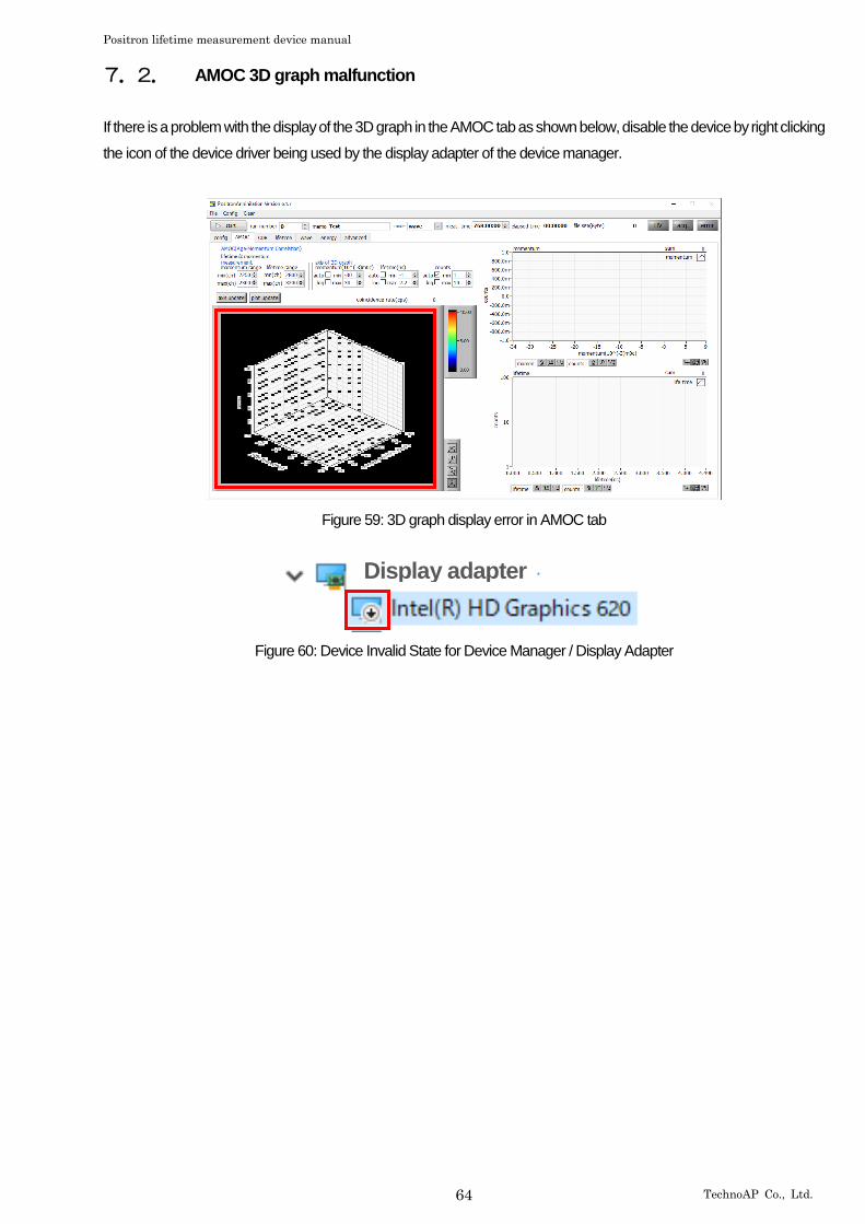
Positron lifetime measurement device manual
64 TechnoAP Co., Ltd.
7.2. AMOC 3D graph malfunction
If there is a problem with the display of the 3D graph in the AMOC tab as shown below, disable the device by right clicking
the icon of the device driver being used by the display adapter of the device manager.
Figure 59: 3D graph display error in AMOC tab
Figure 60: Device Invalid State for Device Manager / Display Adapter
Display adapter

Positron lifetime measurement device manual
65 TechnoAP Co., Ltd.
8. Warranty policy
The warranty conditions of "our product" are as follows.
Warranty period One year from date of purchase.
Guarantee contents Repair or replacement will be carried out in case of breakdown even though you have
used correctly according to this instruction manual within the warranty period
Out of warranty
We do not warranty if the cause of the failure falls under any of the following.
(1) Failure or damage due to misuse or improper repair or modification or disassembly.
(2) Failure and damage due to falling etc.
(3) Breakdown / damage in harsh environments (high temperature / high humidity, under
zero, condensation etc.).
(4) Causes other than the above, other than "our products".
(5) Consumables.
(6) Natural disasters such as fire, earthquake, flood damage, lightning, etc. and breakdown
due to theft.
(7) When the cause of the malfunction is found to be wet
After you start using our products, we assume that you have agreed to all the above items.
CONTACT INFORMATION
TechnoAP Co., Ltd.
ADD 2976-15 Mawatari, Hitachinaka-shi, Ibaraki, 312-0012, Japan
TEL +81-29-350-8011
FAX +81-29-352-9013
WEB http://www.techno-ap.com
Email [email protected]
[Business Hour]: Monday to Friday, 9:30 to 17:00 (Japan Time)
Distributor or Agency