portfolio srinivas somasundaram
TRANSCRIPT

Design Portfolio
Srinivas Somasundaram
Bike Rack
Contents
Shingler Robot
Auto PillDispenser
Pipelined Processor Design
Project LIV POV Display
Accelo - IntruderDetector
In-VehicleStress Buster
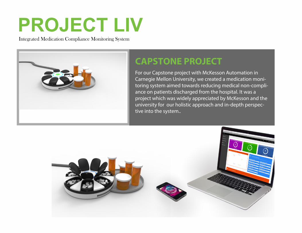
Integrated Medication Compliance Monitoring System
ct LIV video here
PROJECT LIV
This should be replaced by video
For our Capstone project with McKesson Automation in Carnegie Mellon University, we created a medication moni-toring system aimed towards reducing medical non-compli-ance on patients discharged from the hospital. It was a project which was widely appreciated by McKesson and the university for our holistic approach and in-depth perspec-tive into the system..
CAPSTONE PROJECT
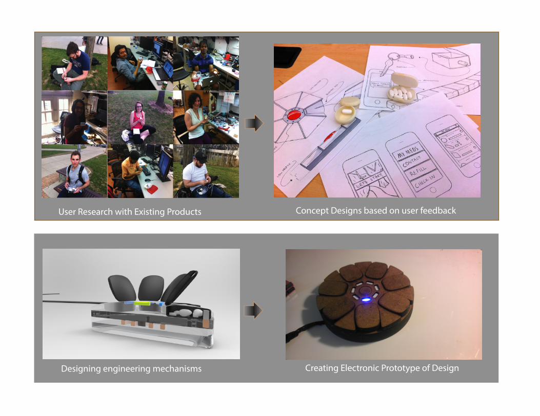
User Research with Existing Products Concept Designs based on user feedback
Designing engineering mechanisms
Prototype Video
Creating Electronic Prototype of Design
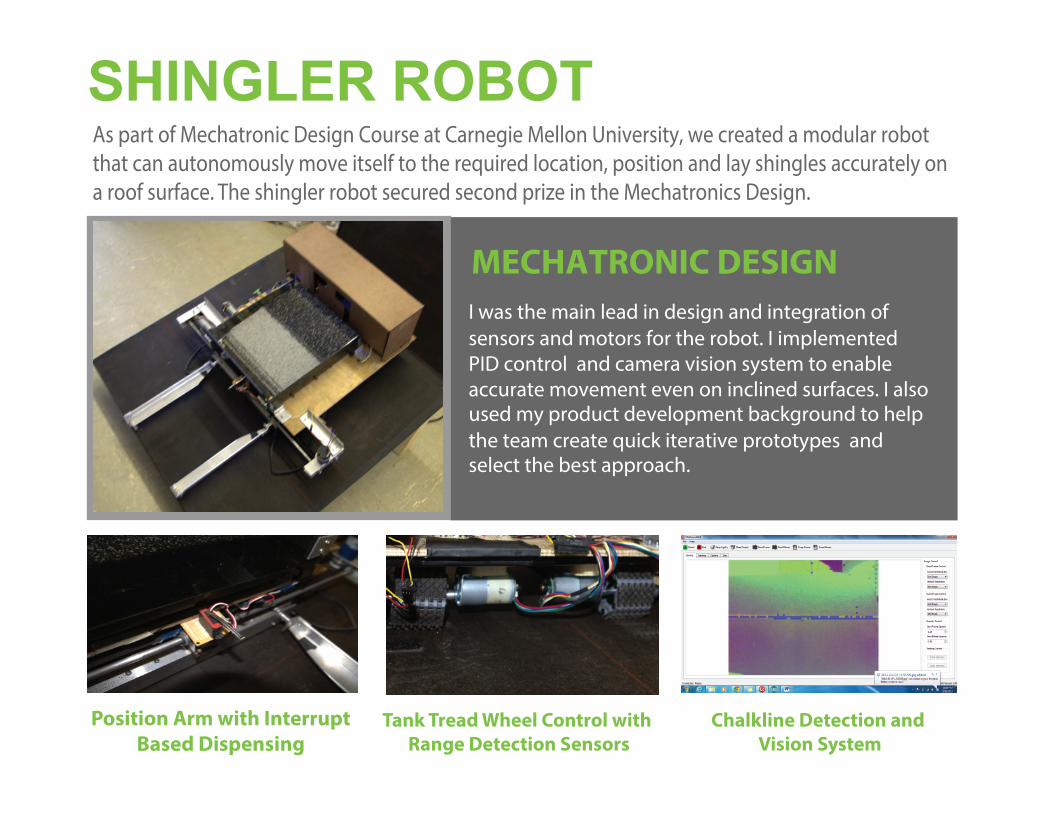
Position Arm with InterruptBased Dispensing
Tank Tread Wheel Control with Range Detection Sensors
SHINGLER ROBOTAs part of Mechatronic Design Course at Carnegie Mellon University, we created a modular robot that can autonomously move itself to the required location, position and lay shingles accurately on a roof surface. The shingler robot secured second prize in the Mechatronics Design.
MECHATRONIC DESIGNI was the main lead in design and integration of sensors and motors for the robot. I implemented PID control and camera vision system to enable accurate movement even on inclined surfaces. I also used my product development background to help the team create quick iterative prototypes and select the best approach.
Chalkline Detection and Vision System
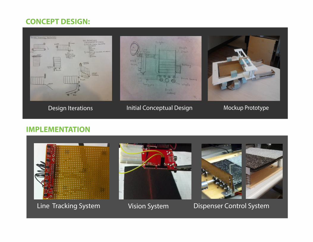
CONCEPT DESIGN:
Design Iterations Initial Conceptual Design Mockup Prototype
IMPLEMENTATION
Line Tracking System Vision System Dispenser Control System
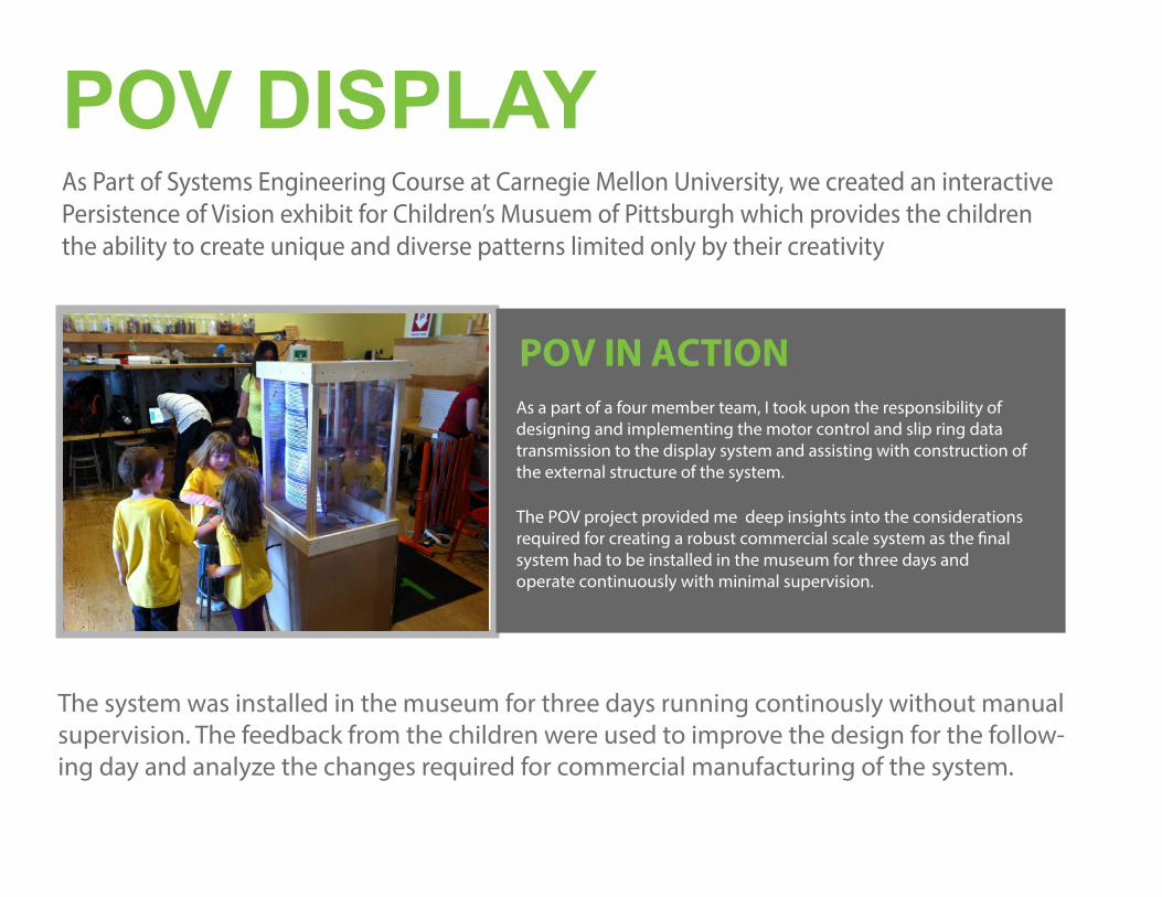
POV DISPLAYAs Part of Systems Engineering Course at Carnegie Mellon University, we created an interactive Persistence of Vision exhibit for Children’s Musuem of Pittsburgh which provides the children the ability to create unique and diverse patterns limited only by their creativity
This should be replaced by video
POV IN ACTIONAs a part of a four member team, I took upon the responsibility of designing and implementing the motor control and slip ring data transmission to the display system and assisting with construction of the external structure of the system.
The POV project provided me deep insights into the considerations required for creating a robust commercial scale system as the �nal system had to be installed in the museum for three days and operate continuously with minimal supervision.
The system was installed in the museum for three days running continously without manual supervision. The feedback from the children were used to improve the design for the follow-ing day and analyze the changes required for commercial manufacturing of the system.
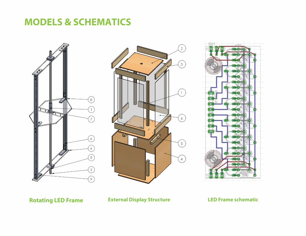
Rotating LED Frame External Display Structure LED Frame schematic
MODELS & SCHEMATICS
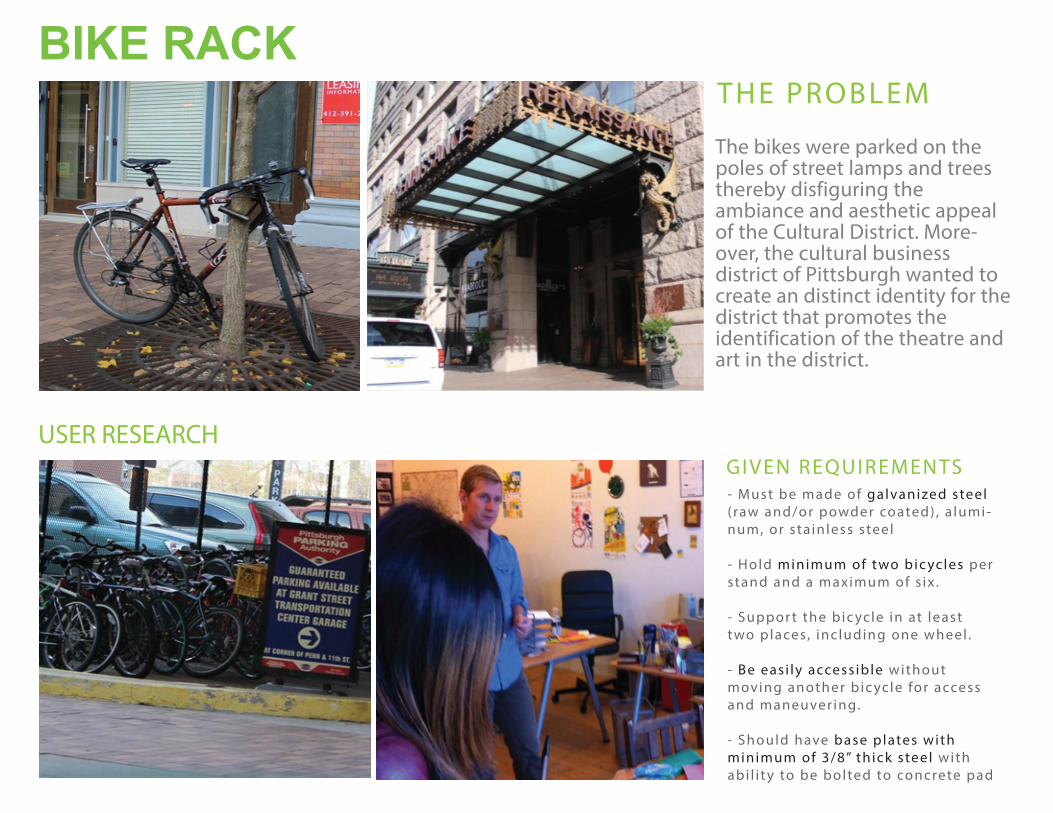
THE PROBLEM
The bikes were parked on the poles of street lamps and trees thereby disfiguring the ambiance and aesthetic appeal of the Cultural District. More-over, the cultural business district of Pittsburgh wanted to create an distinct identity for the district that promotes the identification of the theatre and art in the district.
USER RESEARCHGIVEN REQUIREMENTS- Must be made of galvanized steel( raw and/or powder coated) , a lumi-num, or sta inless steel
- Hold minimum of t wo bic ycles perstand and a maximum of s ix .
- Suppor t the bic ycle in at leastt wo places, inc luding one wheel .
- Be eas i ly access ible withoutmoving another bic ycle for accessand maneuver ing.
- Should have base plates withminimum of 3/8” thick steel withabi l i t y to be bolted to concrete pad
BIKE RACK
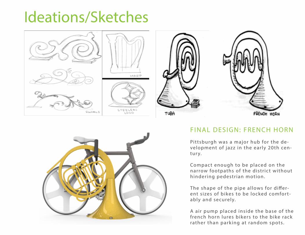
Ideations/Sketches
FINAL DESIGN: FRENCH HORN
Pittsburgh was a major hub for the de-velopment of jazz in the ear ly 20th cen-tur y.
Compac t enough to be placed on the narrow footpaths of the distr ic t without hinder ing pedestr ian motion.
The shape of the pipe a l lows for d i�er-ent s izes of b ikes to be locked comfor t-ably and securely.
A a i r pump placed ins ide the base of the f rench horn lures bikers to the bike rack rather than park ing at random spots.
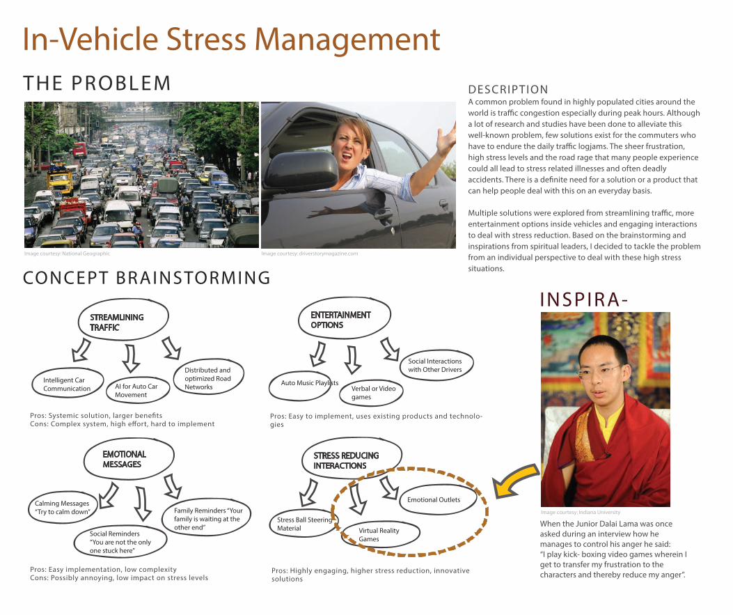
CONCEPT BRAINSTORMING
STREAMLINING TRAFFIC
Intelligent Car Communication
INSPIRA-
THE PROBLEM
When the Junior Dalai Lama was once asked during an interview how he manages to control his anger he said: “I play kick- boxing video games wherein I get to transfer my frustration to the characters and thereby reduce my anger”.
DESCRIPTIONA common problem found in highly populated cities around the world is tra�c congestion especially during peak hours. Although a lot of research and studies have been done to alleviate this well-known problem, few solutions exist for the commuters who have to endure the daily tra�c logjams. The sheer frustration, high stress levels and the road rage that many people experience could all lead to stress related illnesses and often deadly accidents. There is a de�nite need for a solution or a product that can help people deal with this on an everyday basis.
Multiple solutions were explored from streamlining tra�c, more entertainment options inside vehicles and engaging interactions to deal with stress reduction. Based on the brainstorming and inspirations from spiritual leaders, I decided to tackle the problem from an individual perspective to deal with these high stress situations.
AI for Auto Car Movement
Distributed and optimized Road Networks Auto Music Playlists
Verbal or Video games
Social Interactions with Other Drivers
ENTERTAINMENT OPTIONS
Calming Messages“Try to calm down”
Social Reminders“You are not the only one stuck here”
Family Reminders “Your family is waiting at the other end”
EMOTIONAL MESSAGES
Stress Ball Steering Material Virtual Reality
Games
Emotional Outlets
STRESS REDUCING INTERACTIONS
Image courtesy: National Geographic Image courtesy: driverstorymagazine.com
Pros: Systemic solution, larger bene�tsCons: Complex system, high e�ort, hard to implement
Pros: Easy to implement, uses existing products and technolo-gies
Pros: Easy implementation, low complexityCons: Possibly annoying, low impact on stress levels
Pros: Highly engaging, higher stress reduction, innovative solutions
Image courtesy: Indiana University
In-Vehicle Stress Management
In Vehicle Stress Management
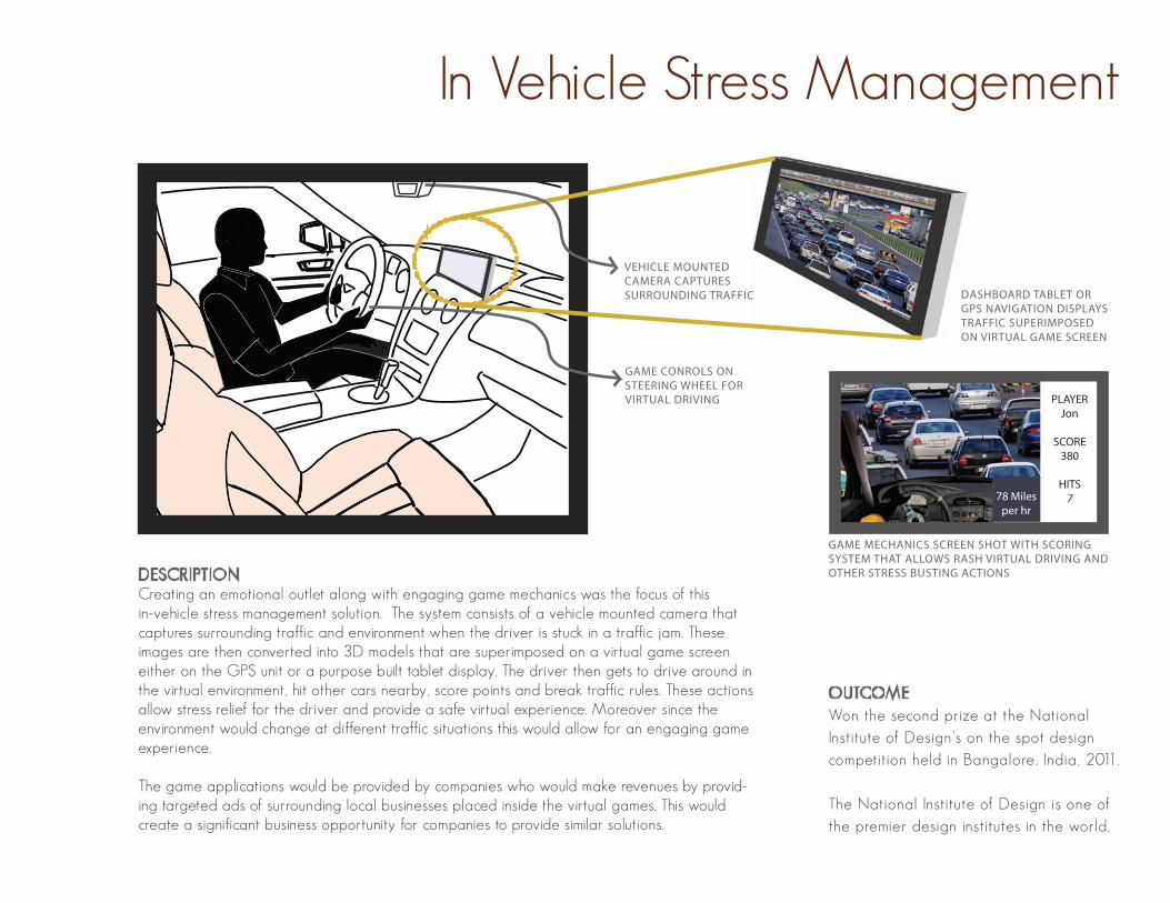
DESCRIPTIONCreating an emotional outlet along with engaging game mechanics was the focus of this in-vehicle stress management solution. The system consists of a vehicle mounted camera that captures surrounding traffic and environment when the driver is stuck in a traffic jam. These images are then converted into 3D models that are superimposed on a virtual game screen either on the GPS unit or a purpose built tablet display. The driver then gets to drive around in the virtual environment, hit other cars nearby, score points and break traffic rules. These actions allow stress relief for the driver and provide a safe virtual experience. Moreover since the environment would change at different traffic situations this would allow for an engaging game experience.
The game applications would be provided by companies who would make revenues by provid-ing targeted ads of surrounding local businesses placed inside the virtual games. This would create a significant business opportunity for companies to provide similar solutions.
PLAYERJon
SCORE380
HITS778 Miles
per hr
VEHICLE MOUNTED CAMERA CAPTURES SURROUNDING TRAFFIC
GAME CONROLS ON STEERING WHEEL FOR VIRTUAL DRIVING
DASHBOARD TABLET OR GPS NAVIGATION DISPLAYS TRAFFIC SUPERIMPOSED ON VIRTUAL GAME SCREEN
GAME MECHANICS SCREEN SHOT WITH SCORING SYSTEM THAT ALLOWS RASH VIRTUAL DRIVING AND OTHER STRESS BUSTING ACTIONS
OUTCOMEWon the second prize at the National Institute of Design’s on the spot design competition held in Bangalore, India, 2011.
The National Institute of Design is one of the premier design institutes in the world.

EXISTING PRODUC TS RESEARCH
THE PROBLEMDESCRIPTIONMost seniors and patients with memory loss or blurry vision have trouble taking the right amount of medication at the prescribed times. Many pill dispensing solutions and medication organizers exist in the market. The problem is that, they all either require manual intervention from patients or require that they read information displayed in order to �nd out the dosage amount. Research has shown that regular and timely consumption of medication can drastically improve recovery rates but no solutions exist today that automatically dispense the right pills at preset times in the right amount of quantity in an a�ordable device.
The fundamental problem arises from the fact that pills come in all shapes and sizes and multiple pills may need to be taken in di�erent combinations at di�erent times. Although the storage problem can be solved by requiring family members to pre organize pills, it is a tricky problem to dispense di�erent size pills through a mechani-cal solution.
After thorough research of existing products in the market and multiple concept iterations, I have ventured in to designing a unique solution with an innovative mechanism to store and dispense the exact type and quantity of pills through an a�ordable and portable consumer device.Image courtesy: http://neuroprotectivelifestyle.com
DESIGN CRITERIAThe device must be able to deliver di�erent kinds of pills at a de�nite time without any manual aggregation of multiple pills by the user.
The exact amount of prescribed dosage must be deliv-ered. Any increase or decrease in the dosage may cause medical di�culties to the user.
The device must be portable and yet have an ample pill carrying capacity so that the pills do not have to be frequently re�lled.
The device must be user friendly and easy to operate. It must also consider the needs of elderly people who are prone to being hearing-impaired, have blurry vision and absent-mindedness.
Re�lling of the pills into the device must be hassle-free to the user. Also the di�erent pill sizes must be taken into account to prevent any inconvenience to the user.
Auto Pill Dispenser
Auto Pill Dispenser
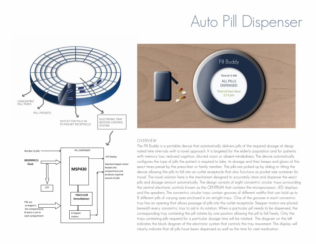
OVERVIEWThe Pill Buddy is a portable device that automatically delivers pills of the required dosage at desig-nated time intervals with a novel approach. It is targeted for the elderly population and for patients with memory loss, reduced cognition, blurred vision or absent-mindedness. The device automatically configures the type of pills the patient is required to take, its dosage and then beeps and glows at the exact times preset by the prescriber or family member. The pills are picked up by sliding or tilting the device allowing the pills to fall into an outlet receptacle that also functions as pocket size container for travel. The novel solution here is the mechanism designed to accurately store and dispense the exact pills and dosage amount automatically. The design consists of eight concentric circular trays surrounding the central electronic controls known as the CENTRUM that contains the microprocessor, LED displays and the speakers. The concentric circular trays contain grooves of different widths that can hold up to 8 different pills of varying sizes enclosed in an airtight trays. One of the grooves in each concentric tray has an opening that allows passage of pills into the outlet receptacle. Stepper motors are placed beneath every concentric tray to aid in its rotation. When a particular pill needs to be dispensed, the corresponding tray containing the pill rotates by one position allowing the pill to fall freely. Only the trays containing pills required for a particular dosage time will be rotated. The diagram on the left indicates the block diagram of the electronic system that controls the tray movement. The display will clearly indicate that all pills have been dispensed as well as the time for next medication.
OUTLET FOR PILLS IN TO POCKET RECEPTACLE
ELECTRONIC TRAY MOTION CONTROL SYSTEM
Pill Buddy
Time 8:15 AM
ALL PILLS DISPENSED
Time of next dose 2:15 pm
Number of pills
LED display (BQ3285E/L) Clock Selected stepper motor
Rotates the compartment and produces required amount of pills
Pills are arranged in the compartments & alarm is set to each compartment
PILL DISPENSER
LCD
MSP430
8 stepper motors
74AC11138 Demultiplexer
PILL POCKETS
CONCENTRIC PILL TRAYS
PRODUCT IDEATION
THE PROBLEM
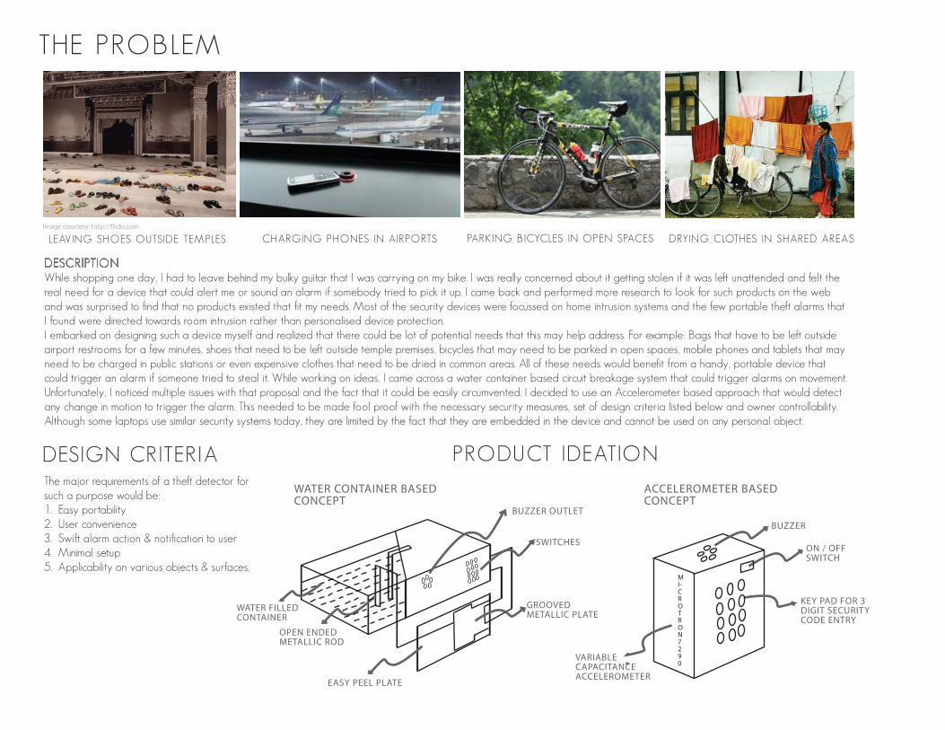
DESCRIPTIONWhile shopping one day, I had to leave behind my bulky guitar that I was carrying on my bike. I was really concerned about it getting stolen if it was left unattended and felt the real need for a device that could alert me or sound an alarm if somebody tried to pick it up. I came back and performed more research to look for such products on the web and was surprised to find that no products existed that fit my needs. Most of the security devices were focussed on home intrusion systems and the few portable theft alarms that I found were directed towards room intrusion rather than personalised device protection.I embarked on designing such a device myself and realized that there could be lot of potential needs that this may help address. For example: Bags that have to be left outside airport restrooms for a few minutes, shoes that need to be left outside temple premises, bicycles that may need to be parked in open spaces, mobile phones and tablets that may need to be charged in public stations or even expensive clothes that need to be dried in common areas. All of these needs would benefit from a handy, portable device that could trigger an alarm if someone tried to steal it. While working on ideas, I came across a water container based circuit breakage system that could trigger alarms on movement. Unfortunately, I noticed multiple issues with that proposal and the fact that it could be easily circumvented. I decided to use an Accelerometer based approach that would detect any change in motion to trigger the alarm. This needed to be made fool proof with the necessary security measures, set of design criteria listed below and owner controllability. Although some laptops use similar security systems today, they are limited by the fact that they are embedded in the device and cannot be used on any personal object.
Image courtesy: http://flickr.com
DESIGN CRITER IAThe major requirements of a theft detector for such a purpose would be:1. Easy portability2. User convenience3. Swift alarm action & notification to user4. Minimal setup5. Applicability on various objects & surfaces.
LEAVING SHOES OUTSIDE TEMPLES CHARGING PHONES IN AIRPORTS PARKING BICYCLES IN OPEN SPACES DRYING CLOTHES IN SHARED AREAS
BUZZER OUTLET
SWITCHES
OPEN ENDED METALLIC ROD
EASY PEEL PLATE
GROOVED METALLIC PLATE
WATER FILLED CONTAINER
WATER CONTAINER BASED CONCEPT
ACCELEROMETER BASED CONCEPT
KEY PAD FOR 3 DIGIT SECURITY CODE ENTRY
ON / OFF SWITCH
BUZZER
VARIABLE CAPACITANCE ACCELEROMETER
MI-CROTR ON 7290
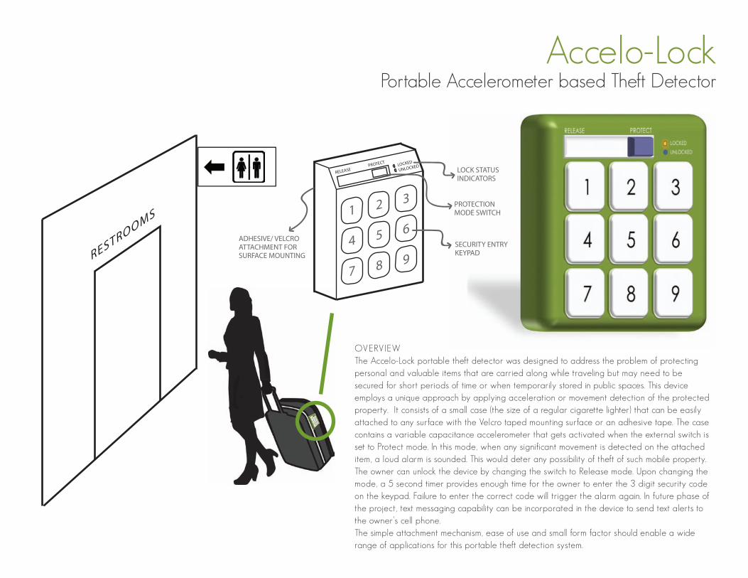
Accelo-LockPortable Accelerometer based Theft Detector
OVERVIEWThe Accelo-Lock portable theft detector was designed to address the problem of protecting personal and valuable items that are carried along while traveling but may need to be secured for short periods of time or when temporarily stored in public spaces. This device employs a unique approach by applying acceleration or movement detection of the protected property. It consists of a small case (the size of a regular cigarette lighter) that can be easily attached to any surface with the Velcro taped mounting surface or an adhesive tape. The case contains a variable capacitance accelerometer that gets activated when the external switch is set to Protect mode. In this mode, when any significant movement is detected on the attached item, a loud alarm is sounded. This would deter any possibility of theft of such mobile property. The owner can unlock the device by changing the switch to Release mode. Upon changing the mode, a 5 second timer provides enough time for the owner to enter the 3 digit security code on the keypad. Failure to enter the correct code will trigger the alarm again. In future phase of the project, text messaging capability can be incorporated in the device to send text alerts to the owner’s cell phone. The simple attachment mechanism, ease of use and small form factor should enable a wide range of applications for this portable theft detection system.
LOCKED
UNLOCKED
RELEASE PROTECT
1
4
7
2
5
8
3
6
9
LOCK STATUSINDICATORS
PROTECTION MODE SWITCH
SECURITY ENTRY KEYPAD
ADHESIVE/ VELCRO ATTACHMENT FOR SURFACE MOUNTINGRESTROOMS
SIMULATION EXPERIMENT
THE PROBLEM
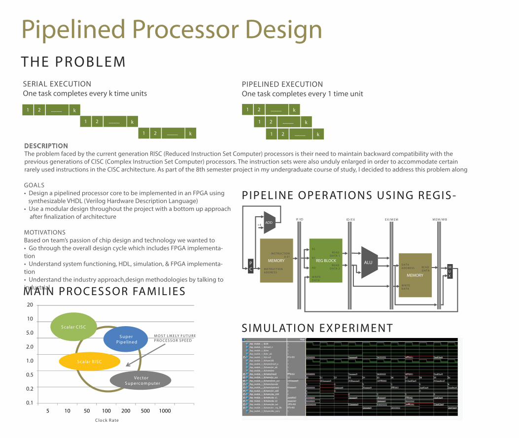
DESCRIPTIONThe problem faced by the current generation RISC (Reduced Instruction Set Computer) processors is their need to maintain backward compatibility with the previous generations of CISC (Complex Instruction Set Computer) processors. The instruction sets were also unduly enlarged in order to accommodate certain rarely used instructions in the CISC architecture. As part of the 8th semester project in my undergraduate course of study, I decided to address this problem along
MAIN PROCESSOR FAMILIES
C lock R ate
0
0.2
0.4
0.6
0.8
1
1.2
5 10 50 100 200 500 1000
Vector S upercom puter
S calar R IS C
S calar C IS C
S uper P ipelined
20
10
5.0
2.0
1.0
0.5
0.2
0.1
M O S T L IK E LY F U T U R EP R O C E S S O R S P E E D
1 2 .......... k
1 2 .......... k
1 2 ..........k
k
1 2 .......... k
1 2 .......... k
1 2 .......... k
SERIAL EXECUTIONOne task completes every k time units
PIPELINED EXECUTIONOne task completes every 1 time unit
MEMORY REG BLOCK
MEMORY
ALU
ADD
PC M
UX
IN S TR U C TIO N A D D R E S S
+4
IN S TR U C TIO N 0-31
R S
R T
R D
W R ITE D A TA
R E A D D A TA 1
R E A D D A TA 2
W R ITE D A TA
D A TA A D D R E S S R E A D
D A TA
IF /ID ID /E X E X /M E M M E M /W B
PIPELINE OPERATIONS USING REGIS-GOALS• Design a pipelined processor core to be implemented in an FPGA using synthesizable VHDL (Verilog Hardware Description Language)• Use a modular design throughout the project with a bottom up approach after �nalization of architecture
MOTIVATIONSBased on team’s passion of chip design and technology we wanted to • Go through the overall design cycle which includes FPGA implementa-tion• Understand system functioning, HDL, simulation, & FPGA implementa-tion• Understand the industry approach,design methodologies by talking to industrial
Pipelined Processor Design
Pipelined Processor Design
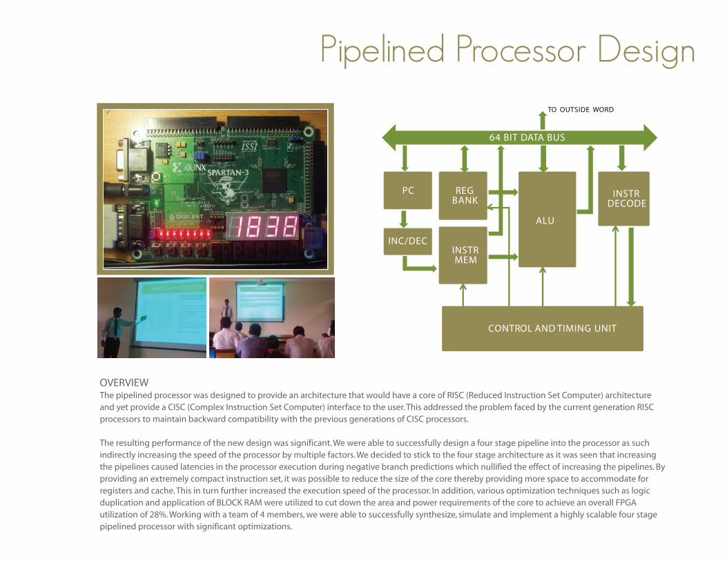
OVERVIEWThe pipelined processor was designed to provide an architecture that would have a core of RISC (Reduced Instruction Set Computer) architecture and yet provide a CISC (Complex Instruction Set Computer) interface to the user. This addressed the problem faced by the current generation RISC processors to maintain backward compatibility with the previous generations of CISC processors.
The resulting performance of the new design was significant. We were able to successfully design a four stage pipeline into the processor as such indirectly increasing the speed of the processor by multiple factors. We decided to stick to the four stage architecture as it was seen that increasing the pipelines caused latencies in the processor execution during negative branch predictions which nullified the effect of increasing the pipelines. By providing an extremely compact instruction set, it was possible to reduce the size of the core thereby providing more space to accommodate for registers and cache. This in turn further increased the execution speed of the processor. In addition, various optimization techniques such as logic duplication and application of BLOCK RAM were utilized to cut down the area and power requirements of the core to achieve an overall FPGA utilization of 28%. Working with a team of 4 members, we were able to successfully synthesize, simulate and implement a highly scalable four stage pipelined processor with significant optimizations.
64 BIT DATA BUS
TO OUTSIDE WORD
INSTR DECODE
ALU
CONTROL AND TIMING UNIT
INSTR MEM
REG BANK
INC/DEC
PC