polymer tantalum capacitors for automotive applications · polymer tantalum capacitors for...
TRANSCRIPT
Polymer Tantalum Capacitors for Automotive Applications
Jayson Young and Javaid Qazi Kemet Corporation
PO Box 5928, Greenville SC 29606
Phone: 864-963-6300
Introduction
The use of tantalum capacitors with polymer cathode systems continues to experience wide spread use
throughout many industry segments given the many advantages this cathode system offers. Adoption of
this technology began within the consumer electronics market with rapid adoption in notebook and desktop
computer applications. Within a short period of time, enterprise and infrastructure industries began using
the technology with wide spread usage across many different application areas. During the past five years,
polymer tantalum capacitors have gained popularity in medical, avionics and military designs as well given
the level of performance and reliability these devices have demonstrated in the field during the past fifteen
years. Today, manufacturers of polymer tantalum capacitors have set their sights on the automotive
industry as the next area of growth. This segment of users seeks newer technologies that can offer
performance advantages but still meet the requirements for extreme environments and application
conditions as defined in the Automotive Electronics Council (AEC) Q-200 Document for passive
component qualification.
Intrinsically conductive polymers such as PPY and PEDOT have become the polymer material sets of
choice for tantalum capacitors. These polymers offer the best combination of manufacturability,
performance and reliability and represent nearly 100% of the processes in use today. However, over the
last 15 years, polymer capacitors have proven to be incapable of consistently passing certain environmental
test conditions that were once considered common capabilities for their predecessor, the MnO2 Surface
Mount Tantalum Capacitor. Test conditions that are considered most challenging for polymer technology
include high temperature testing at a test temperature of 125°C and high humidity testing at the commonly
accepted 85°C/85%RH test condition. Due to these gaps in product performance, MnO2 Surface Mount
Tantalum Capacitors have remained the component technology of choice within industry segments that
require these higher temperature and humidity conditions. While it is unlikely that polymer tantalum
capacitors will be capable of performing in application conditions of 150°C to 200°C in the near future, the
potential for these capacitors passing the AEC Q-200 requirements is close at hand.
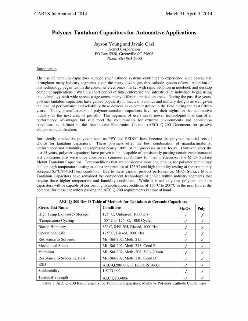
AEC Q-200 Rev D Table of Methods for Tantalum & Ceramic Capacitors
Stress Test Name Conditions MnO2 Poly
High Temp Exposure (Storage) 125° C, Unbiased, 1000 Hrs ✓ ✗
Temperature Cycling -55° C to 125° C, 1000 Cycles ✓ ✓
Biased Humidity 85° C, 85% RH, Biased, 1000 Hrs ✓ ✗
Operational Life 125° C, Biased, 1000 Hrs ✓ ✗
Resistance to Solvents Mil-Std-202, Meth. 215 ✓ ✓
Mechanical Shock Mil-Std-202, Meth. 213, Cond F ✓ ✓
Vibration Mil-Std-202, Meth. 208, 5G’s-20min ✓ ✓
Resistance to Soldering Heat Mil-Std-202, Meth. 210, Cond D ✓ ✓
ESD AEC-Q200- 002 or ISO/DIS 10605 ✓ ✓
Solderability J-STD-002 ✓ ✓
Terminal Strength AEC Q200-006 ✓ ✓ Table 1: AEC Q-200 Requirements for Tantalum Capacitors: MnO2 vs Polymer Cathode Capabilities
CARTS International 2014 March 31-April 3, 2014
Test Requirement Needs vs. Component Capabilities
The automotive industry’s interest in a 125°C rated product is centered on the need to pass both a 1000
hours life test with applied voltage and a 1000 hours unbiased (storage) life test. Most designers report that
there are no real expectations for the circuit to be exposed to a 125°C environment during the life of the
product. However, design-in of products that do not meet the complete requirements of the AEC Q-200
Document require increased efforts within their automotive organizations to gather the necessary approvals
to use the component as exceptions to the Q-200 Document often must be documented and submitted for
special approvals.
Interest in an 85°C/85%RH capable product follows a similar path to the 125°C capabilities. This humidity
test condition is often reported to be an accelerated test condition used to assess the corrosive
characteristics of the product over a long period of exposure time to temperature and humidity. Commonly
accepted acceleration factors for other component technologies imply that if a device can pass the
85°C/85%RH condition for 1000 hours, the device will be capable of withstanding the environmental
conditions placed on it in the field over a period of five to ten years at more realistic temperatures and
humidity conditions. The conversion of this test condition to an exact temperature and humidity over a
period of years is a topic of frequent discussion. But regardless, the test condition continues to grow in
popularity as industries outside the automotive industry have started to adopt this test condition in recent
years as well.
For polymer tantalum capacitors, there is much debate over the linkage of 85°C/85%RH testing to these
real world conditions. While polymer capacitors typically struggle to pass the 85°C/85%RH test condition
for the full 1000 hours test time, these devices have been in active use in numerous application conditions
for many years during which time no systemic issues have been observed. Known applications that have
depended on polymer tantalum capacitors in humid environments for five to ten years or more include such
applications as base stations, traffic signaling, aviation, electronic billboards, automotive (in-cabin),
commercial marine, industrial lighting and industrial machinery applications.
The issue with both the humidity tests as well as the life tests is that both tests have the potential to create
failure mechanisms that are not observed at more real-world conditions as evidenced by the long and
successful performance history these components have had in the field. Despite attempts by polymer
tantalum capacitor manufacturers to direct the industry away from 85°C/85%RH testing for polymer
tantalum capacitors and instead use a condition such as 40°C/95%RH or 60°C/90%RH, interest in the
85°C/85%RH test condition remains in place given the multitude of other component technologies that are
not sensitive to this test condition.
Achieving 125°C Capability
Temperature extremes in excess of 85°C have been shown to have an impact on the DF and ESR of
polymer tantalum capacitors over time. While component manufacturers do demonstrate capabilities to
pass 105°C (and some limited component offerings to 125°C conditions) for 2000 hours at biased and
unbiased conditions, an allowance is often added for increases in DF and ESR values at post-test
measurement. Continued use of these devices at a constant application temperature of 85°C to 105°C over
a period of years will result in a continuously increasing DF and ESR. Given enough time, these
characteristics can reach a point in which the application fails to perform correctly.
Extended exposure of polymer to air (primary oxygen) at elevated temperature results in oxidation of the
polymer thus increasing the DF and ESR1 of the component. In the absence of oxygen, exposure to 125°C
alone (under inert atmosphere) does not have a significant effect on the polymer1 and hence provides a way
for producing 125°C capable components. To address the challenges polymer tantalum capacitors face in
passing these 125°C life test conditions, enhancements to the component’s construction are necessary to
slow the rate of polymer oxidation and allow for more stabilized performance through the 1000 hours test
time. Enhancements primarily focus on improved packaging that slows or prevents hot air from reaching
the polymer layers. By slowing or preventing the hot air from reaching the polymer, oxidation of the
polymer will be reduced or eliminated throughout the 1000 hours of test time thus meeting the
requirements of the test2.
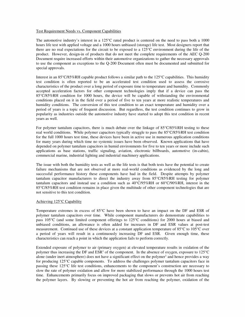
To demonstrate the improvements in performance observed with devices specifically designed to pass the
125°C life tests, a test and control group were processed using the standard manufacturing lines that
produce this product line. For the test group, special process steps were added to the manufacturing line
which were focused on enhanced packaging that would slow the rate of polymer oxidation. All other
process steps were identical to the control group. The part number selected for this evaluation was an EIA
Case Code 3528-20 (B Case) size with a capacitance value of 220uF and a voltage rating of 6.3V. A mid
range ESR value of 45mOhms was selected. Samples were collected from the two groups, board mounted
using two Pb-Free reflow passes and placed on a 125°C life test with 0.67Vr applied per the Q-200
Document. Product performance was monitored throughout the 1000 hours test time with capacitance, DF,
ESR and leakage measurement intervals of 0, 250, 500 and 1000 hours.
Figure 1: 125°C Life Test, 1000 Hrs @ 0.67Vr, Control Group, Capacitance
Figure 2: 125°C Life Test, 1000 Hrs @ 0.67Vr, Test Group, Capacitance
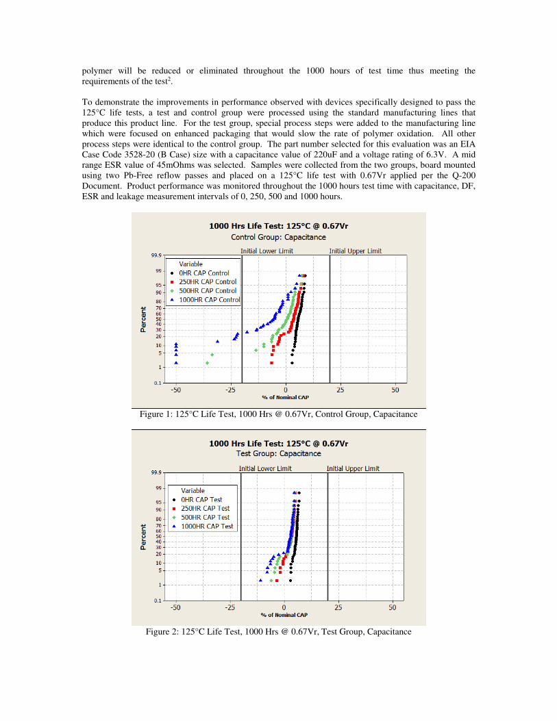
When assessing the performance of capacitance during a high temperature life test, tantalum capacitors
would typically show a decrease in capacitance from the initial to 250 hours measurement. This decrease
in capacitance is due to additional drying of the component during high temperature testing. Slightly less
noticeable capacitance decreases may be observed at 500 and 1000 hours as further drying occurs.
However, when conducting a 125°C life test on polymer cathode capacitors, other elements are at work that
can result in a different behavior.
Figure 3: 125°C Life Test, 1000 Hrs @ 0.67Vr, Control Group, DF
Figure 4: 125°C Life Test, 1000 Hrs @ 0.67Vr, Test Group, DF
Figures 1 and 2 highlight the differences observed in capacitance between the two groups throughout the
test time. In assessing the control group, it can be observed that a small portion of the population has
experienced a more notable decrease in capacitance at the 250 and 500 hours measurements compared to
the rest of the population. It was also observed that this same small group experiences a more significant
increase in DF and ESR compared to the rest of the population. This added reduction in capacitance would
be attributed to the oxidization effects of the polymer as less active polymer is in contact with the dielectric.
The reason for why this small group of components experienced a more rapid rate of oxidation relates to
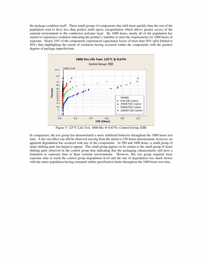
the package condition itself. These small groups of components that shift more quickly than the rest of the
population tend to have less than perfect mold epoxy encapsulation which allows greater access of the
external environment to the conductive polymer layer. By 1000 hours, nearly all of the population has
started to experience oxidation indicating the product’s inability to meet the requirements for 1000 hours of
exposure. Nearly 10% of the components experienced capacitance losses of more than 50% (plot limited to
50%) thus highlighting the extent of oxidation having occurred within the components with the greatest
degrees of package imperfections.
Figure 5: 125°C Life Test, 1000 Hrs @ 0.67Vr, Control Group, ESR
In comparison, the test group has demonstrated a more stabilized behavior throughout the 1000 hours test
time. A dry out effect can still be observed moving from the initial to 250 hours measurement, however, no
apparent degradation has occurred with any of the components. At 500 and 1000 hours, a small group of
faster shifting parts has begun to appear. This small group appears to be similar to the small group of faster
shifting parts observed in the control group thus indicating that the packaging enhancements still have a
limitation to exposure time at these extreme environments. However, this test group required more
exposure time to reach the control group degradation level and the rate of degradation was much slower
with the entire population having remained within specification limits throughout the 1000 hours test time.
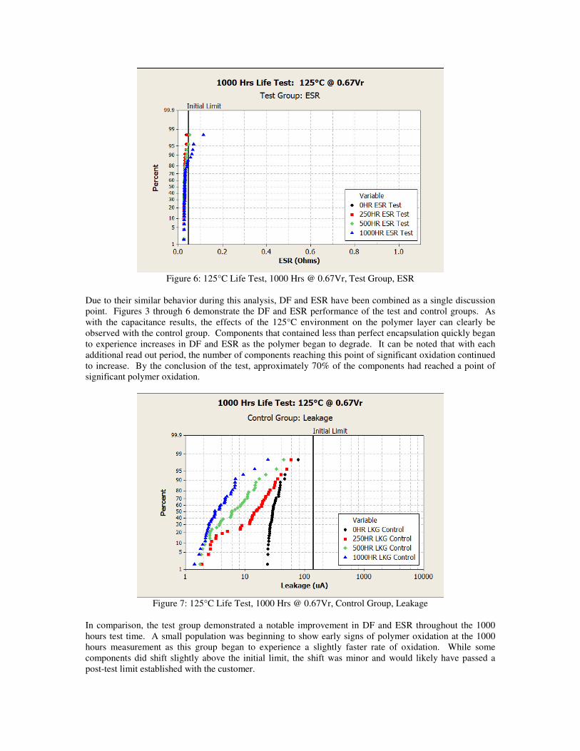
Figure 6: 125°C Life Test, 1000 Hrs @ 0.67Vr, Test Group, ESR
Due to their similar behavior during this analysis, DF and ESR have been combined as a single discussion
point. Figures 3 through 6 demonstrate the DF and ESR performance of the test and control groups. As
with the capacitance results, the effects of the 125°C environment on the polymer layer can clearly be
observed with the control group. Components that contained less than perfect encapsulation quickly began
to experience increases in DF and ESR as the polymer began to degrade. It can be noted that with each
additional read out period, the number of components reaching this point of significant oxidation continued
to increase. By the conclusion of the test, approximately 70% of the components had reached a point of
significant polymer oxidation.
Figure 7: 125°C Life Test, 1000 Hrs @ 0.67Vr, Control Group, Leakage
In comparison, the test group demonstrated a notable improvement in DF and ESR throughout the 1000
hours test time. A small population was beginning to show early signs of polymer oxidation at the 1000
hours measurement as this group began to experience a slightly faster rate of oxidation. While some
components did shift slightly above the initial limit, the shift was minor and would likely have passed a
post-test limit established with the customer.
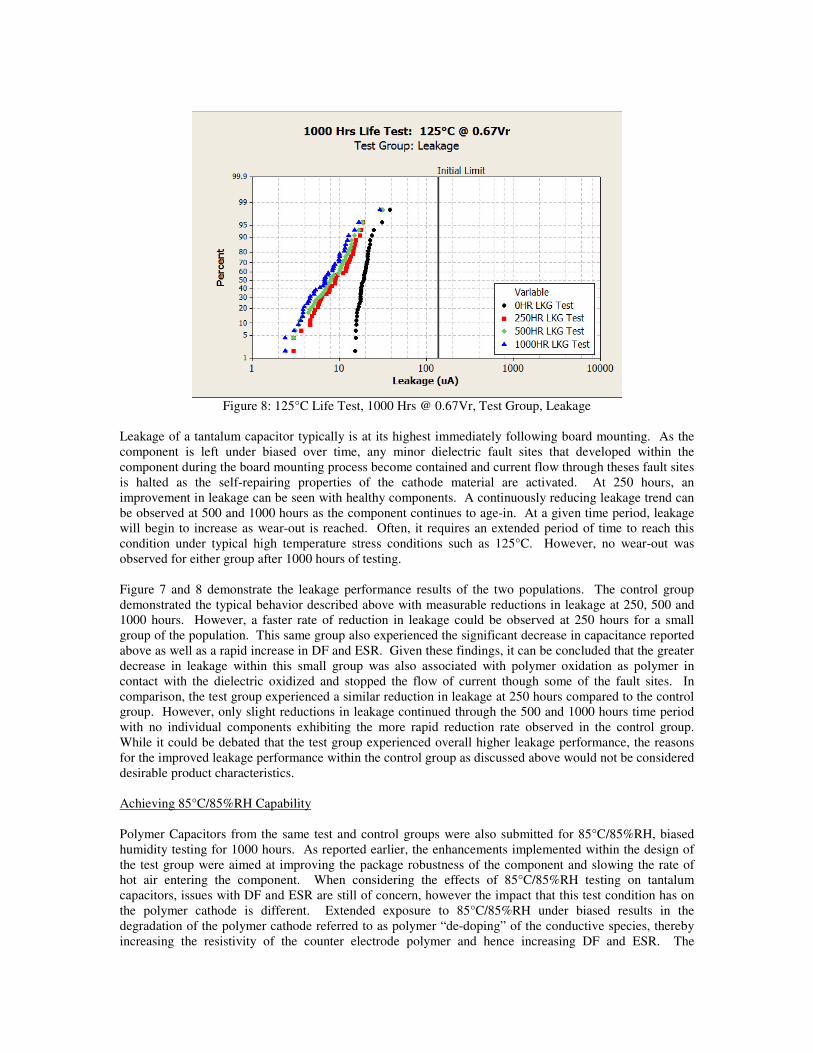
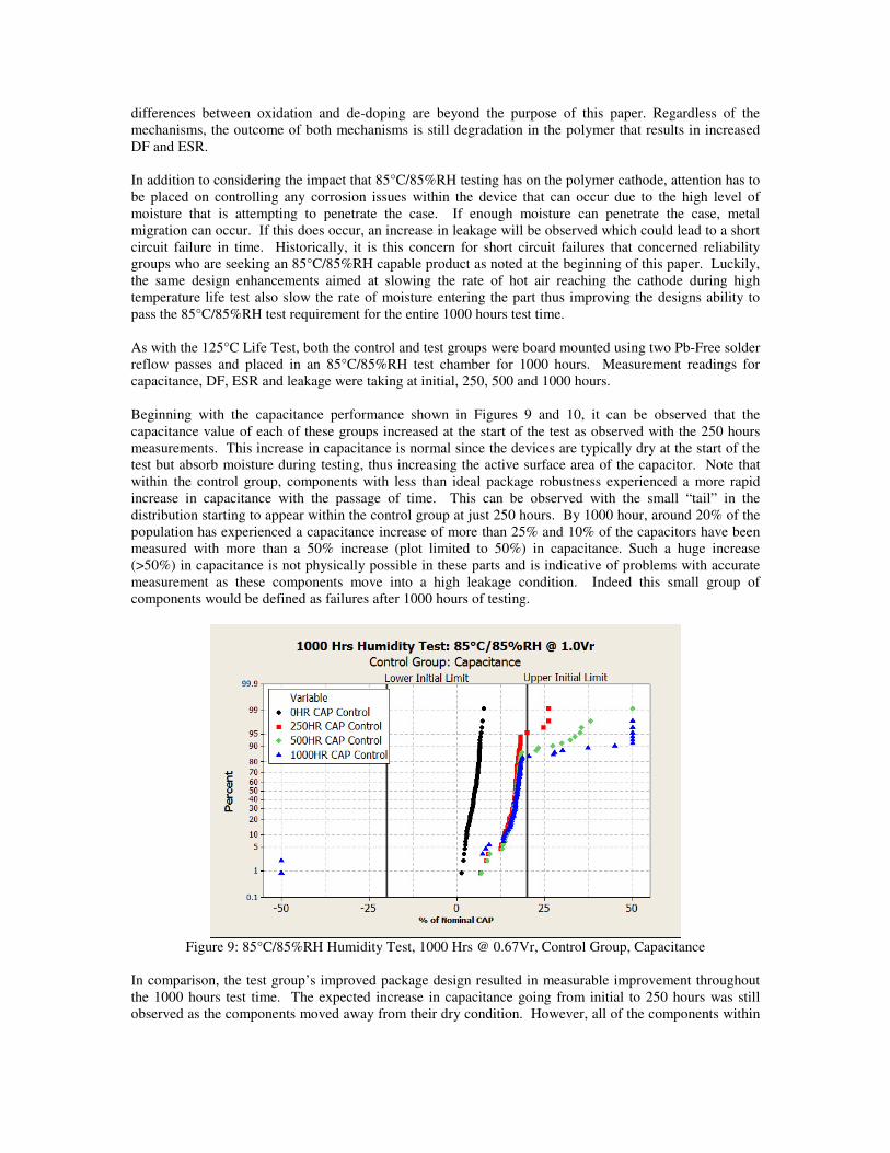
Figure 8: 125°C Life Test, 1000 Hrs @ 0.67Vr, Test Group, Leakage
Leakage of a tantalum capacitor typically is at its highest immediately following board mounting. As the
component is left under biased over time, any minor dielectric fault sites that developed within the
component during the board mounting process become contained and current flow through theses fault sites
is halted as the self-repairing properties of the cathode material are activated. At 250 hours, an
improvement in leakage can be seen with healthy components. A continuously reducing leakage trend can
be observed at 500 and 1000 hours as the component continues to age-in. At a given time period, leakage
will begin to increase as wear-out is reached. Often, it requires an extended period of time to reach this
condition under typical high temperature stress conditions such as 125°C. However, no wear-out was
observed for either group after 1000 hours of testing.
Figure 7 and 8 demonstrate the leakage performance results of the two populations. The control group
demonstrated the typical behavior described above with measurable reductions in leakage at 250, 500 and
1000 hours. However, a faster rate of reduction in leakage could be observed at 250 hours for a small
group of the population. This same group also experienced the significant decrease in capacitance reported
above as well as a rapid increase in DF and ESR. Given these findings, it can be concluded that the greater
decrease in leakage within this small group was also associated with polymer oxidation as polymer in
contact with the dielectric oxidized and stopped the flow of current though some of the fault sites. In
comparison, the test group experienced a similar reduction in leakage at 250 hours compared to the control
group. However, only slight reductions in leakage continued through the 500 and 1000 hours time period
with no individual components exhibiting the more rapid reduction rate observed in the control group.
While it could be debated that the test group experienced overall higher leakage performance, the reasons
for the improved leakage performance within the control group as discussed above would not be considered
desirable product characteristics.
Achieving 85°C/85%RH Capability
Polymer Capacitors from the same test and control groups were also submitted for 85°C/85%RH, biased
humidity testing for 1000 hours. As reported earlier, the enhancements implemented within the design of
the test group were aimed at improving the package robustness of the component and slowing the rate of
hot air entering the component. When considering the effects of 85°C/85%RH testing on tantalum
capacitors, issues with DF and ESR are still of concern, however the impact that this test condition has on
the polymer cathode is different. Extended exposure to 85°C/85%RH under biased results in the
degradation of the polymer cathode referred to as polymer “de-doping” of the conductive species, thereby
increasing the resistivity of the counter electrode polymer and hence increasing DF and ESR. The
differences between oxidation and de-doping are beyond the purpose of this paper. Regardless of the
mechanisms, the outcome of both mechanisms is still degradation in the polymer that results in increased
DF and ESR.
In addition to considering the impact that 85°C/85%RH testing has on the polymer cathode, attention has to
be placed on controlling any corrosion issues within the device that can occur due to the high level of
moisture that is attempting to penetrate the case. If enough moisture can penetrate the case, metal
migration can occur. If this does occur, an increase in leakage will be observed which could lead to a short
circuit failure in time. Historically, it is this concern for short circuit failures that concerned reliability
groups who are seeking an 85°C/85%RH capable product as noted at the beginning of this paper. Luckily,
the same design enhancements aimed at slowing the rate of hot air reaching the cathode during high
temperature life test also slow the rate of moisture entering the part thus improving the designs ability to
pass the 85°C/85%RH test requirement for the entire 1000 hours test time.
As with the 125°C Life Test, both the control and test groups were board mounted using two Pb-Free solder
reflow passes and placed in an 85°C/85%RH test chamber for 1000 hours. Measurement readings for
capacitance, DF, ESR and leakage were taking at initial, 250, 500 and 1000 hours.
Beginning with the capacitance performance shown in Figures 9 and 10, it can be observed that the
capacitance value of each of these groups increased at the start of the test as observed with the 250 hours
measurements. This increase in capacitance is normal since the devices are typically dry at the start of the
test but absorb moisture during testing, thus increasing the active surface area of the capacitor. Note that
within the control group, components with less than ideal package robustness experienced a more rapid
increase in capacitance with the passage of time. This can be observed with the small “tail” in the
distribution starting to appear within the control group at just 250 hours. By 1000 hour, around 20% of the
population has experienced a capacitance increase of more than 25% and 10% of the capacitors have been
measured with more than a 50% increase (plot limited to 50%) in capacitance. Such a huge increase
(>50%) in capacitance is not physically possible in these parts and is indicative of problems with accurate
measurement as these components move into a high leakage condition. Indeed this small group of
components would be defined as failures after 1000 hours of testing.
Figure 9: 85°C/85%RH Humidity Test, 1000 Hrs @ 0.67Vr, Control Group, Capacitance
In comparison, the test group’s improved package design resulted in measurable improvement throughout
the 1000 hours test time. The expected increase in capacitance going from initial to 250 hours was still
observed as the components moved away from their dry condition. However, all of the components within
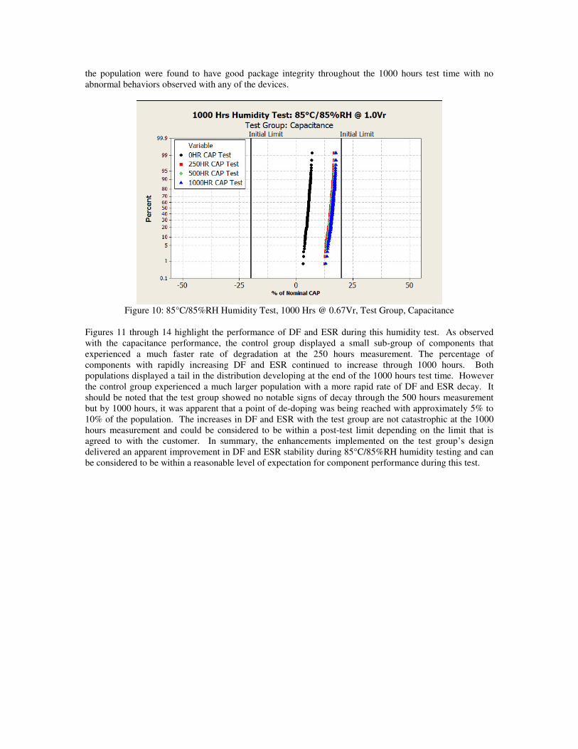
the population were found to have good package integrity throughout the 1000 hours test time with no
abnormal behaviors observed with any of the devices.
Figure 10: 85°C/85%RH Humidity Test, 1000 Hrs @ 0.67Vr, Test Group, Capacitance
Figures 11 through 14 highlight the performance of DF and ESR during this humidity test. As observed
with the capacitance performance, the control group displayed a small sub-group of components that
experienced a much faster rate of degradation at the 250 hours measurement. The percentage of
components with rapidly increasing DF and ESR continued to increase through 1000 hours. Both
populations displayed a tail in the distribution developing at the end of the 1000 hours test time. However
the control group experienced a much larger population with a more rapid rate of DF and ESR decay. It
should be noted that the test group showed no notable signs of decay through the 500 hours measurement
but by 1000 hours, it was apparent that a point of de-doping was being reached with approximately 5% to
10% of the population. The increases in DF and ESR with the test group are not catastrophic at the 1000
hours measurement and could be considered to be within a post-test limit depending on the limit that is
agreed to with the customer. In summary, the enhancements implemented on the test group’s design
delivered an apparent improvement in DF and ESR stability during 85°C/85%RH humidity testing and can
be considered to be within a reasonable level of expectation for component performance during this test.
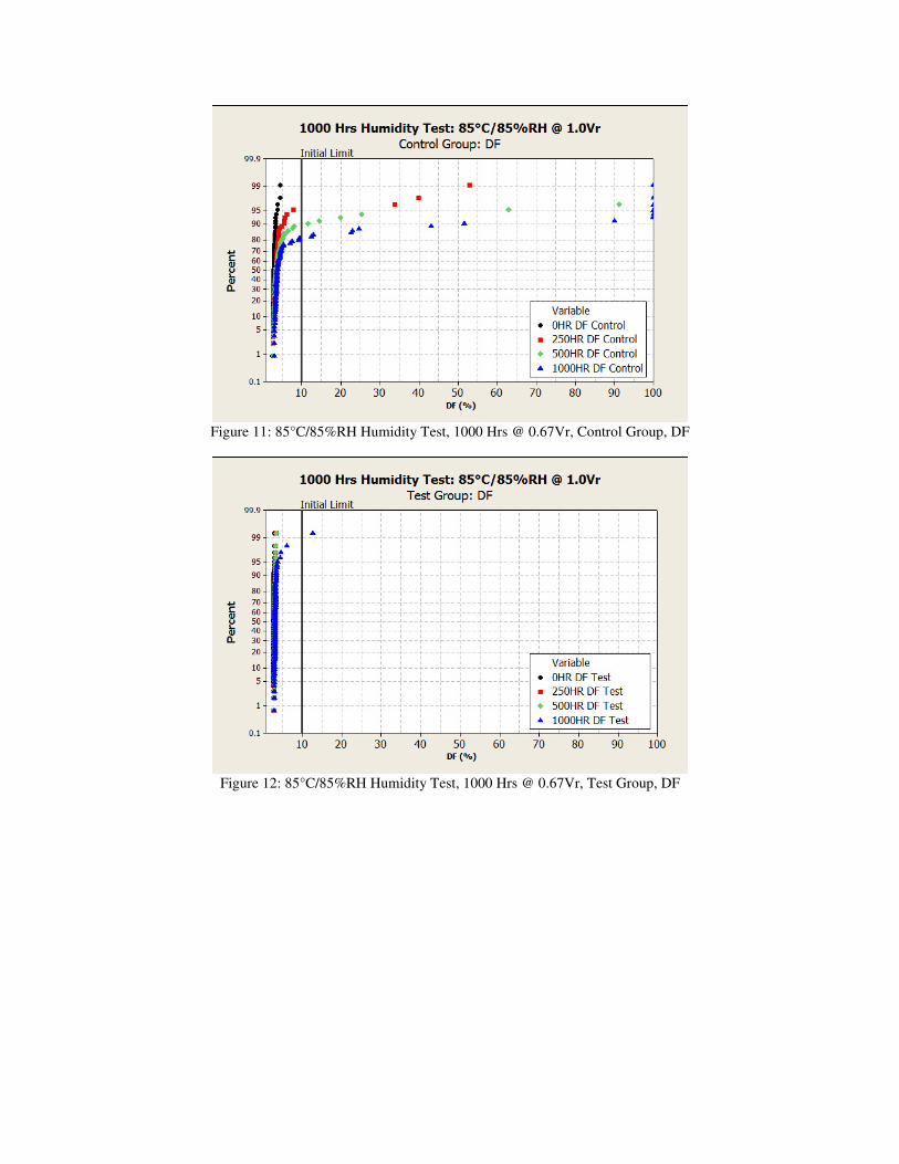
Figure 11: 85°C/85%RH Humidity Test, 1000 Hrs @ 0.67Vr, Control Group, DF
Figure 12: 85°C/85%RH Humidity Test, 1000 Hrs @ 0.67Vr, Test Group, DF
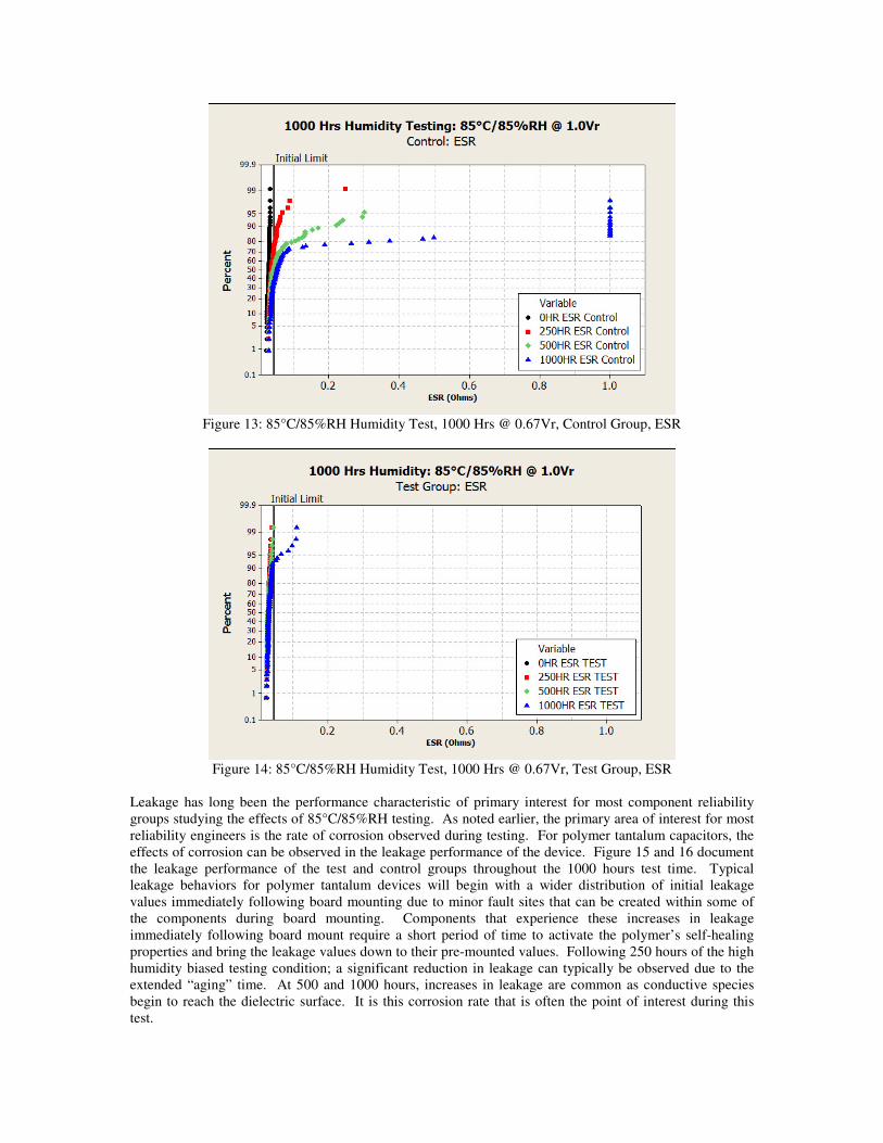
Figure 13: 85°C/85%RH Humidity Test, 1000 Hrs @ 0.67Vr, Control Group, ESR
Figure 14: 85°C/85%RH Humidity Test, 1000 Hrs @ 0.67Vr, Test Group, ESR
Leakage has long been the performance characteristic of primary interest for most component reliability
groups studying the effects of 85°C/85%RH testing. As noted earlier, the primary area of interest for most
reliability engineers is the rate of corrosion observed during testing. For polymer tantalum capacitors, the
effects of corrosion can be observed in the leakage performance of the device. Figure 15 and 16 document
the leakage performance of the test and control groups throughout the 1000 hours test time. Typical
leakage behaviors for polymer tantalum devices will begin with a wider distribution of initial leakage
values immediately following board mounting due to minor fault sites that can be created within some of
the components during board mounting. Components that experience these increases in leakage
immediately following board mount require a short period of time to activate the polymer’s self-healing
properties and bring the leakage values down to their pre-mounted values. Following 250 hours of the high
humidity biased testing condition; a significant reduction in leakage can typically be observed due to the
extended “aging” time. At 500 and 1000 hours, increases in leakage are common as conductive species
begin to reach the dielectric surface. It is this corrosion rate that is often the point of interest during this
test.
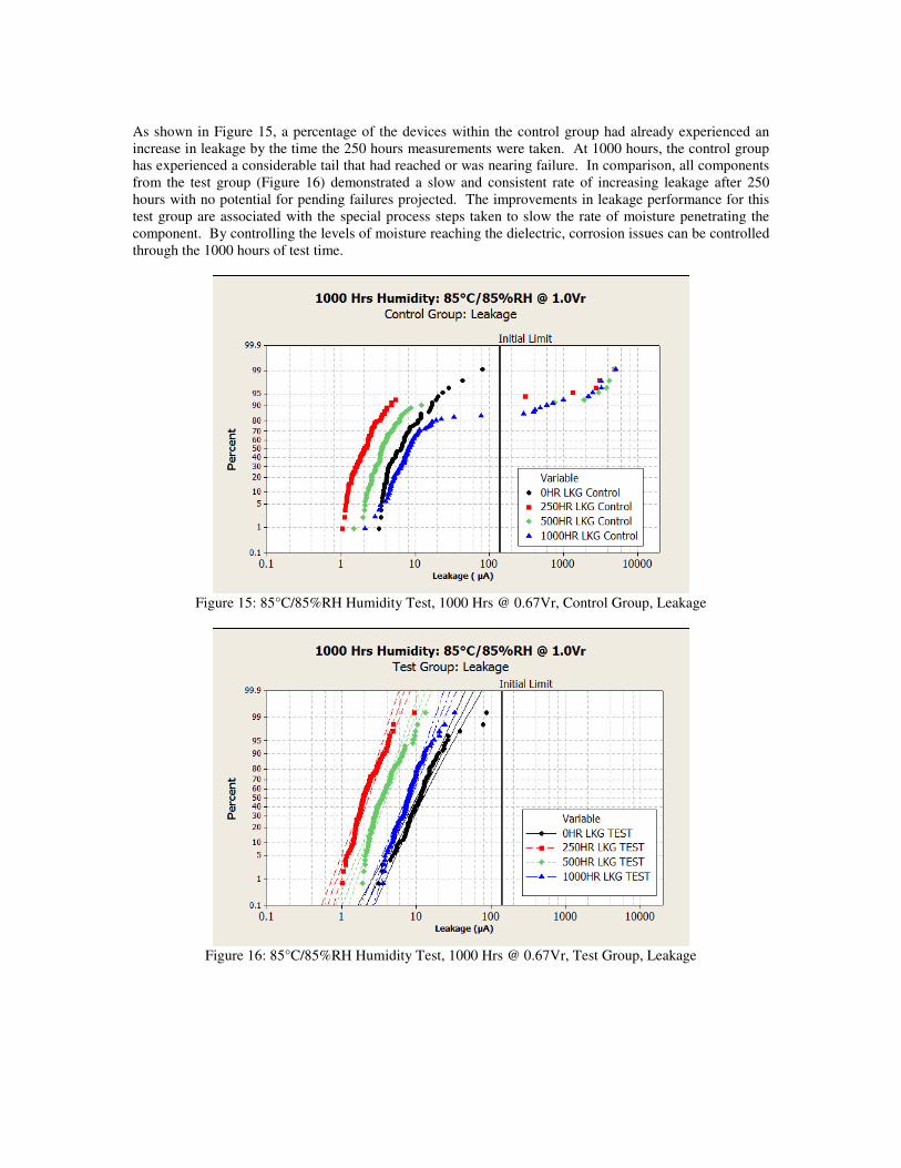
As shown in Figure 15, a percentage of the devices within the control group had already experienced an
increase in leakage by the time the 250 hours measurements were taken. At 1000 hours, the control group
has experienced a considerable tail that had reached or was nearing failure. In comparison, all components
from the test group (Figure 16) demonstrated a slow and consistent rate of increasing leakage after 250
hours with no potential for pending failures projected. The improvements in leakage performance for this
test group are associated with the special process steps taken to slow the rate of moisture penetrating the
component. By controlling the levels of moisture reaching the dielectric, corrosion issues can be controlled
through the 1000 hours of test time.
Figure 15: 85°C/85%RH Humidity Test, 1000 Hrs @ 0.67Vr, Control Group, Leakage
Figure 16: 85°C/85%RH Humidity Test, 1000 Hrs @ 0.67Vr, Test Group, Leakage
Summary
Based on the current results of special design efforts implemented on polymer tantalum capacitors to meet
all of the requirements defined in the AEC Q-200 Document, a design solution that meets all of these
requirements is close at hand. Enhancements over the standard product design are clearly needed to
minimize the impact that extreme external environments have on both the polymer cathode and metal
migration during testing. As demonstrated above, it is possible to design a polymer tantalum capacitor that
can pass the harsh test conditions of 125°C Life Testing and 85°C/85%RH Humidity Testing for the full
1000 hours requirement. It is projected that polymer tantalum capacitor options for a fully qualified AEC
Q-200 product will be available in the very near future as processes and materials are finalized and moved
into a mass production phase.
Bibliography 1 Y Jin, Q. Chen, P Lessner, “Thermal Stability Investigation of PEDOT Films from Chemical Oxidation
and Prepolymerized Dispersion” Electrochemistry, 81, (10), 801-03, (2013)
2 E Reed, J Chen, J Marshall, J Paulsen, R Weisenborn; “New 125°C Capable Tantalum Polymer
Capacitors”, CARTS-EUROPE 2003 Proceedings of the Capacitor and Resistor Symposium (2003)