polymer electrolyte membrane fuel cell as a hydrogen flow rate monitoring device
TRANSCRIPT
ORIGINAL PAPER
Polymer electrolyte membrane fuel cell as a hydrogen flowrate monitoring device
S. Giddey & S. P. S. Badwal
Received: 16 January 2012 /Revised: 6 June 2012 /Accepted: 7 June 2012 /Published online: 24 July 2012# Springer-Verlag 2012
Abstract There is a substantial demand for hydrogenflow rate monitoring devices in applications where hy-drogen is utilised or produced and which include oilrefineries, ammonia production, food and chemical in-dustries, coal gasification, methane steam reforming andwater electrolysis. In this paper, a polymer electrolytemembrane (PEM) fuel cell has been demonstrated formeasuring accurate flow rates of hydrogen or hydrogen-containing gases. The concept involves applying a con-stant voltage to a PEM fuel cell to oxidise the entirehydrogen supplied to the anode compartment of the fuelcell and observing limiting current values attained andrelating these to the hydrogen flow rates. PEM fuelcells with an active area of 50 cm2 were constructedand used to accurately measure the flow rates of hydro-gen up to 170 mL/min. A device with a capability tomonitor significantly higher hydrogen flow rates can beconstructed by using several cells in a stacking arrange-ment or by using electrically isolated cells in a singledevice. The paper discusses advantages and limitationsof the technique and the flow rate-measuring responsefor gases containing 5–100 % hydrogen. The responsetime for hydrogen gas was of the order of 1–2 min.However, the fuel cell flow field design can be opti-mised for faster response times.
Keywords Hydrogen . Fuel cell . Hydrogen flow ratemonitor . Limiting current
Introduction
Total global hydrogen production is over 60 million metrictons per annum. Hydrogen is mainly used in ammonia(mainly fertiliser) production, petroleum industry for con-version of heavy oils to lighter oil fractions and in otherindustrial processes (food, chemical, metallurgical, medicaland aerospace) [1, 2]. Only a very small percentage of thetotal global hydrogen produced is currently used as anenergy carrier. Hydrogen is also considered as an energycurrency and storage media especially for intermittent re-newable energy sources. It is also considered as a clean fuelfor future transport vehicles either for combustion in aninternal combustion engine or consumption in a fuel cell[3–5]. Therefore, the demand for hydrogen as a fuel isexpected to grow considerably in the future.
There is a substantial demand for hydrogen sensors andhydrogen flow rate monitoring devices in most applicationswhere hydrogen is utilised or produced and is expected togrow with increased production and utilisation of hydrogen.A number of electrochemical sensors for detecting hydrogenhave been reported in the literature and are used widely inindustry [6–10] with the major application being safetymonitoring. Hydrogen flow rate monitoring devices arerequired not only in industries where hydrogen is utilised(oil refineries; ammonia production; and food, chemical andmetallurgical industries) but also in processes where hydro-gen is produced (coal gasification, methane steam reform-ing, electrolysis, etc.). Typical devices used are volumetric,mechanical or thermal mass flow sensors, the cost andversatility varying with the type of device.
Hydrogen sensors based on solid polymer electrolytemembranes (PEMs) are typically amperometric devicesand are based on measuring limiting current to determinehydrogen concentrations in the gas phase from parts per
S. Giddey (*) : S. P. S. BadwalCSIRO Energy Technology,Private Bag 33,Clayton South 3169, Victoria, Australiae-mail: [email protected]
Ionics (2013) 19:523–528DOI 10.1007/s11581-012-0757-1
million level to 5–10 % [8–10]. Hydrogen supplied to theanode is oxidised to generate protons and electrons byapplying voltage to the cell. Protons transported throughthe membrane to the cathode are converted back to hydro-gen in the absence of oxygen and to water in the presence ofoxygen. If sufficient voltage is applied to a PEM fuel cell,the limiting current will be achieved due to diffusion limi-tation of the reactant reaching the anode/membrane inter-face. The limiting current can be directly related to theconcentration of hydrogen in the gas stream using the Far-aday law.
There is very little information in the literature about theuse of polymer electrolyte membrane cells as a flow ratemonitoring devices for hydrogen or hydrogen-containinggases. For these devices to operate effectively and efficient-ly with fast response, the gas flow field design and the PEMcell configuration are expected to play a critical role. In thispaper, a simple and versatile device based on polymerelectrolyte membrane has been described which can be usedeither for measuring hydrogen concentration in a gas streamor flow rates of a hydrogen-containing gas. It is based onmeasuring the limiting current and relating it to the flow rateof hydrogen. It can be manufactured by utilising the existingPEM fuel cell materials, manufacturing capability and in-frastructure. Although there are limitations as to the hydro-gen flow rates that can be measured with a single cell, multi-cell stacks or several electrically isolated sequentiallyconnected cells can be incorporated in a single device tototally consume hydrogen to reach a limiting current condi-tion. The sum of total current in all cells will be proportionalto the hydrogen concentration in the gas stream. This way,significantly higher hydrogen flow rates can be monitored.The applications for such devices include monitoring resid-ual hydrogen in the exit gas in fuel cells (for safety moni-toring and enhanced fuel consumption), in oil refineries andfood chemical and metallurgical industry applications. Also,with the increasing growth in hydrogen production andutilisation as a fuel, the demand for such devices is expectedto increase.
Experimental details
Polymer electrolyte membrane cells with an active area of50 cm2 were constructed, and experiments were performedusing dry hydrogen or hydrogen/nitrogen mixtures withknown hydrogen concentration supplied to the hydrogen(anode) electrode and humidified air supply to the oxygen(cathode) electrode of the cell. Membrane electrode assem-blies used for this purpose consisted of hydrogen and airelectrodes on both sides of a Nafion N115 proton-conducting membrane (PEM) with a thickness of 125 μm.Each electrode consisted of a three-layer arrangement
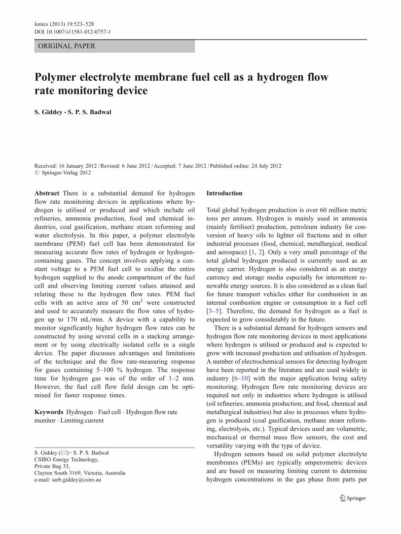
namely a gas diffusion layer, a catalyst layer and an ionomerlayer deposited on a 0.35-mm thick 25 wt% wet-proofed (tomake it partially hydrophobic) carbon paper (TGPH-120Toray carbon paper). The gas diffusion layer was preparedby screen printing Vulcan XC-72 carbon containing PTFEand the catalyst layer by screen printing 20 wt% Pt/Ccatalyst mixed with Nafion solution (5 wt%). The ionomerlayer was deposited by lightly brush coating a 5 wt% Nafionsolution on top of the catalyst layer. Typical Pt catalystloadings achieved were 0.4 mg/cm2/electrode. The mem-brane electrode assembly was hot pressed at 130 °C at apressure of 50 kg/cm2. The cell was assembled in the testfixture with the help of resin-impregnated graphite plates(supplied by UCAR) on both sides of the cell. The hydrogenside graphite plate consisted of a parallel double serpentineflow field to ensure complete utilisation of hydrogen andair-side flow field consisted of a cross-channel parallel flowfield. The channel cross section (width×depth) on the anodeas well as on the cathode side graphite plates was 2×1.5 mm. Figure 1 shows a schematic design of the serpen-tine flow field of the hydrogen interconnect plate. Theoverall dimensions of the each plate were 102×102 mmcross section. The thicknesses of the hydrogen and air-sideinterconnect plates were 5 and 10 mm, respectively. Theflow field of each plate covered an area of 70×70 mm. Thecomplete cell fabrication and assembly details and the teststation employed to carry out the experiments are reportedelsewhere in the literature [11, 12].
A DC power supply (Powerbox PBX4220-50) in a volt-age limiting and current compliance mode was used to applyvoltage to the cell. Steady-state values of limiting currentswere measured for different values of hydrogen inlet flowrates controlled by using a pre-calibrated Bronkhorst HI-TEC mass flow controller (MFC). Hydrogen flow rates weremeasured for the different setting of the MFC by employing
Alignmentholes
Connectingblind channel
SerpentineFlow channels
Gas feederholes
Fig. 1 Schematic of the serpentine flow field design of the hydrogen(anodic) side interconnect graphite plate
524 Ionics (2013) 19:523–528
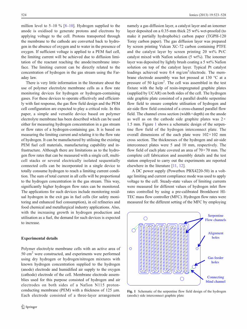
a volumetric flow measuring device (Bios Definer 220). Thedata acquisition system, based on Doric data logger (Digi-trend 235), was used to continuously record the current andcell voltage at a rate of six samples per minute. The hydrogen-based gases employed were industrial grade 99.5 %H2,10.3 % (±0.2 %) H2 in N2 and 5 % (over ±0.5 %) H2 in N2.Humidified air was supplied to the cathode chamber of the cellfor the purpose of humidification of the membrane, and dryhydrogen-containing gases were supplied to the anode cham-ber of the cell. The measurements were made at room tem-perature (~22 °C). Figure 2 shows the schematic of theexperimental setup employed for monitoring flow rates ofhydrogen-containing gases based on limiting current measure-ments. In this setup on the cell exit side, two gas bubblers hadto be used to visually make sure that the entire hydrogen gas isutilised in the cell. Another reason for this was to prevent anyair being sucked back into the fuel chamber from the atmo-sphere on the fuel exit side, due to vacuum being created bycomplete utilisation of hydrogen when the limiting currentwas achieved. The limiting current values were obtained bysetting the gas flow rates in the range of 20 to 175 mL/min.The limiting current condition was attained by controlling thecell voltage such that in the second bubbler, the fluid level inthe submerged tube stayed levelled with that of the fluid in themain body of the bubbler. In the case of measurements on 5and 10.3 %H2 in nitrogen gas mixtures, the setup did notrequire the presence of any gas bubbler on the fuel chamberexit as there was always balance of the unconsumed gas(nitrogen and some impurities) flowing from the exit, afterthe consumption of hydrogen (in the gas mixture) inside thecell.
Results and discussion
PEM fuel cells have been used as hydrogen-sensing devicesin the past [6–10] based on limiting current measurements.
These systems can also be used as hydrogen flow-monitoring devices. When the voltage is applied to a PEMfuel cell, hydrogen supplied to the anode is oxidised toprotons and electrons; the protons transported through themembrane to the cathode are converted back to hydrogen inthe absence of oxygen (pumping mode) and to water in thepresence of oxygen in the fuel cell mode. Provided thatdesign parameter and operating conditions are set correctly,a limiting current condition would be achieved with time. Atthis point, the limiting current value is directly related to theflow rate of hydrogen or hydrogen-containing gases by theFaraday law. For pure hydrogen, the simplified relationshipis as follows:
Hydrogen flow rate (in millilitres per minute)06×104×(Vm / 2F)×Limiting current (in ampere).
In the above equation, Vm and F are the molar volume ofhydrogen in litres and the Faraday's constant (96,487 cou-lombs/mol), respectively.
The applied voltage must be kept below the thermo-neutral voltage of 1.48 V [13] to avoid electrolysis of waterpresent in the fuel chamber either due to some moisture insupplied gases or through diffusion of water from the airside where water is formed in the electrochemical reaction.
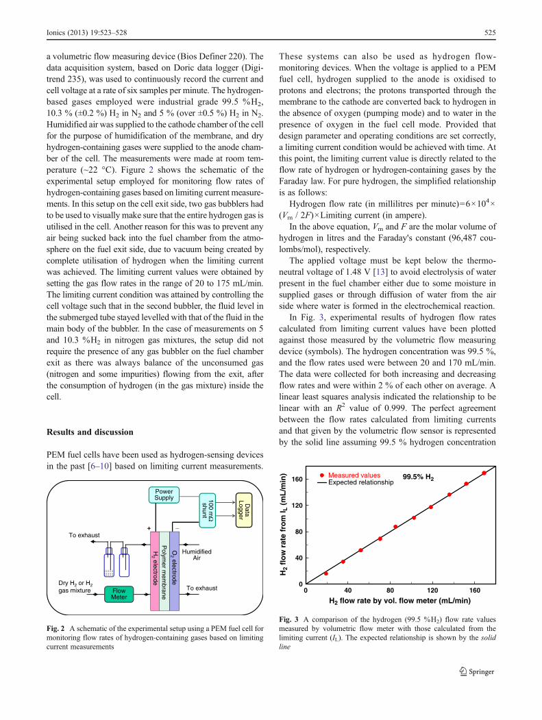
In Fig. 3, experimental results of hydrogen flow ratescalculated from limiting current values have been plottedagainst those measured by the volumetric flow measuringdevice (symbols). The hydrogen concentration was 99.5 %,and the flow rates used were between 20 and 170 mL/min.The data were collected for both increasing and decreasingflow rates and were within 2 % of each other on average. Alinear least squares analysis indicated the relationship to belinear with an R2 value of 0.999. The perfect agreementbetween the flow rates calculated from limiting currentsand that given by the volumetric flow sensor is representedby the solid line assuming 99.5 % hydrogen concentration
Polym
er mem
braneH
2electrodeDry H2 or H2
gas mixture Flow Meter
To exhaust
To exhaust
HumidifiedAir
Power Supply
+ _
100 mΩ
shunt
Data
Logger
O2
electrode
Fig. 2 A schematic of the experimental setup using a PEM fuel cell formonitoring flow rates of hydrogen-containing gases based on limitingcurrent measurements
0
40
80
120
160
0 40 80 120 160
H2 flow rate by vol. flow meter (mL/min)
H2
flo
w r
ate
fro
m I L
(m
L/m
in) Measured values
Expected relationship99.5% H2
Fig. 3 A comparison of the hydrogen (99.5 %H2) flow rate valuesmeasured by volumetric flow meter with those calculated from thelimiting current (IL). The expected relationship is shown by the solidline
Ionics (2013) 19:523–528 525
and that all of it is consumed in the cell. In general, therewas an excellent agreement between the expected and linearleast squares fitted data. The maximum deviation observedfor any data point from the expected relationship was 3 %with an average error of about 1 % for all flow rates. Giventhat there is some error associated with volumetric flowmeter especially for low flow rates, the relationship betweenthe limiting current data and actual flow rates was consid-ered to be excellent. These experiments were repeated with adifferent fuel cell, and results for both calculated and exper-imental data produced similar level of agreement betweenexpected and measured flow rates.
The operating temperature of the fuel cell is one of theparameters that determines the overvoltage/resistive lossesacross different components of the cell/stack. The operatingtemperature is determined by the heat management of thecell/stack in terms of heat produced, absorbed, removed anddissipated by the cell to the atmosphere. It would only havea bearing on the operating cell voltage to achieve the limit-ing current condition, without having any adverse impact onthe limiting current value itself.
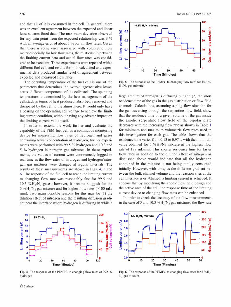
In order to extend the work further and evaluate thecapability of the PEM fuel cell as a continuous monitoringdevice for measuring flow rates of hydrogen and gasescontaining lower concentration of hydrogen, further experi-ments were performed with 99.5 % hydrogen and 10.3 and5 % hydrogen in nitrogen gas mixtures. In these experi-ments, the values of current were continuously logged inreal time as the flow rates of hydrogen and hydrogen/nitro-gen gas mixtures were changed at regular intervals. Theresults of these measurements are shown in Figs. 4, 5 and6. The response of the fuel cell to reach the limiting currentto changing flow rate was reasonably fast for 99.5 and10.3 %H2/N2 gases; however, it became sluggish for the5 %H2/N2 gas mixture and for higher flow rates (>100 mL/min). Two main possible reasons for this may be (1) thedilution effect of nitrogen and the resulting diffusion gradi-ent near the interface where hydrogen is diffusing in while a
large amount of nitrogen is diffusing out and (2) the shortresidence time of the gas in the gas distribution or flow fieldchannels. Calculations, assuming a plug flow situation forthe gas traversing through the serpentine flow field, showthat the residence time of a given volume of the gas insidethe anodic serpentine flow field of the bipolar platedecreases with the increasing flow rate as shown in Table 1for minimum and maximum volumetric flow rates used inthis investigation for each gas. The table shows that theresidence time varies from 0.13 to 0.97 s, with the minimumvalue obtained for 5 %H2/N2 mixture at the highest flowrate of 177 mL/min. This shorter residence time for fasterflow rates in addition to the dilution effect of nitrogen asdiscussed above would indicate that all the hydrogencontained in the mixture is not being totally consumedinitially. However, with time, as the diffusion gradient be-tween the bulk channel volume and the reaction sites at thecell interface is established, a limiting current is achieved. Itappears that by modifying the anodic flow field design andthe active area of the cell, the response time of the limitingcurrent device to changing flow rates can be enhanced.
In order to check the accuracy of the flow measurementsin the case of 5 and 10.3 %H2/N2 gas mixtures, the flow rate
0
40
80
120
160
200
0
2
4
6
8
10
12
14
16
0 20 40 60 80 100 120
H2
flo
w r
ate
(mL
/min
)C
ell v
olt
age
(mV
)
Lim
itin
g c
urr
ent
(A)
Time (Minutes)
99.5% H2
Fig. 4 The response of the PEMFC to changing flow rates of 99.5 %hydrogen
0
20
40
60
80
100
0.0
0.2
0.4
0.6
0.8
1.0
0 10 20 30 40 50
Gas
flo
w r
ate
(mL
/min
)
Lim
itin
g c
urr
ent
(A)
Time (Minutes)
10.3% H2/N2 mixture
Fig. 5 The response of the PEMFC to changing flow rates for 10.3 %H2/N2 gas mixture
0
50
100
150
200
250
300
0.0
0.2
0.4
0.6
0.8
1.0
1.2
0 10 20 30 40 50 60
Gas
flo
w r
ate
(mL
/min
)
Lim
itin
g c
urr
ent
(A)
Time (Minutes)
5% H2/N2 mixture
Fig. 6 The response of the PEMFC to changing flow rates for 5 %H2/N2 gas mixture
526 Ionics (2013) 19:523–528
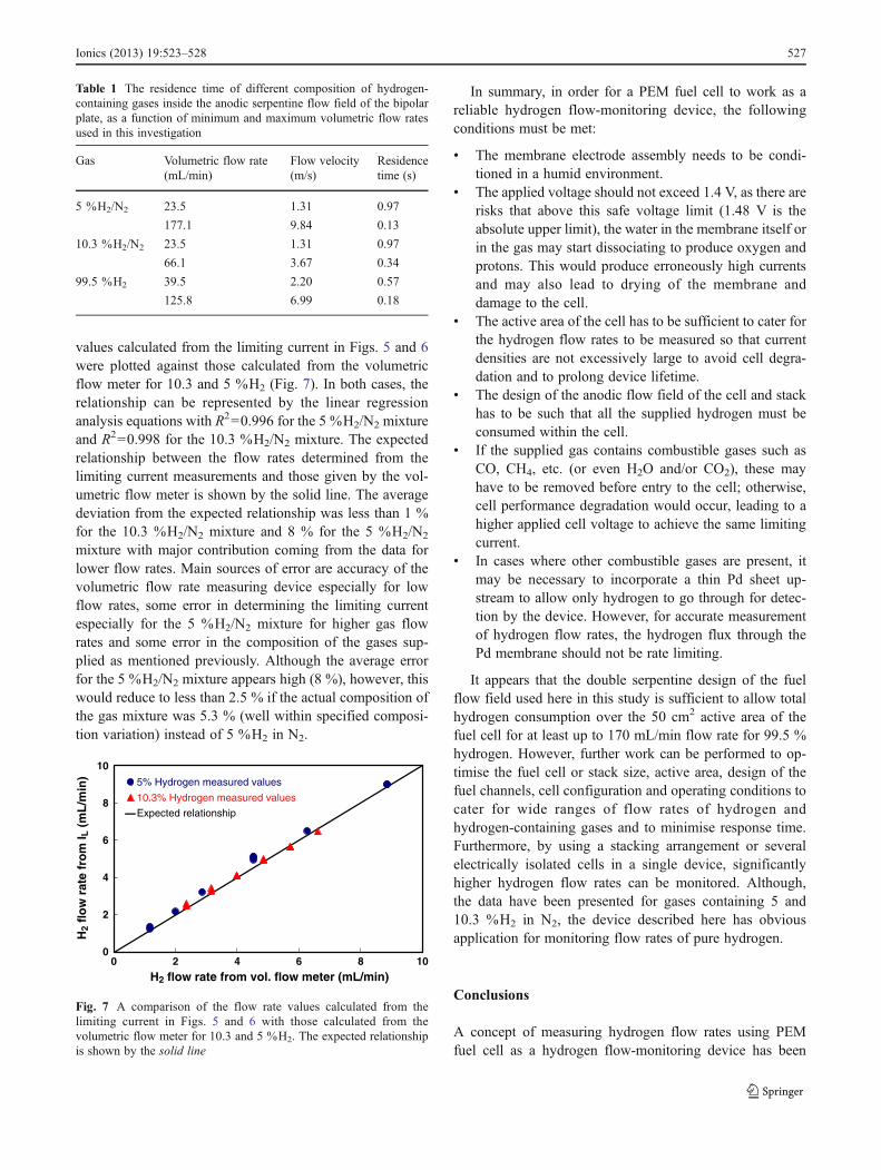
values calculated from the limiting current in Figs. 5 and 6were plotted against those calculated from the volumetricflow meter for 10.3 and 5 %H2 (Fig. 7). In both cases, therelationship can be represented by the linear regressionanalysis equations with R200.996 for the 5 %H2/N2 mixtureand R200.998 for the 10.3 %H2/N2 mixture. The expectedrelationship between the flow rates determined from thelimiting current measurements and those given by the vol-umetric flow meter is shown by the solid line. The averagedeviation from the expected relationship was less than 1 %for the 10.3 %H2/N2 mixture and 8 % for the 5 %H2/N2
mixture with major contribution coming from the data forlower flow rates. Main sources of error are accuracy of thevolumetric flow rate measuring device especially for lowflow rates, some error in determining the limiting currentespecially for the 5 %H2/N2 mixture for higher gas flowrates and some error in the composition of the gases sup-plied as mentioned previously. Although the average errorfor the 5 %H2/N2 mixture appears high (8 %), however, thiswould reduce to less than 2.5 % if the actual composition ofthe gas mixture was 5.3 % (well within specified composi-tion variation) instead of 5 %H2 in N2.
In summary, in order for a PEM fuel cell to work as areliable hydrogen flow-monitoring device, the followingconditions must be met:
& The membrane electrode assembly needs to be condi-tioned in a humid environment.
& The applied voltage should not exceed 1.4 V, as there arerisks that above this safe voltage limit (1.48 V is theabsolute upper limit), the water in the membrane itself orin the gas may start dissociating to produce oxygen andprotons. This would produce erroneously high currentsand may also lead to drying of the membrane anddamage to the cell.
& The active area of the cell has to be sufficient to cater forthe hydrogen flow rates to be measured so that currentdensities are not excessively large to avoid cell degra-dation and to prolong device lifetime.
& The design of the anodic flow field of the cell and stackhas to be such that all the supplied hydrogen must beconsumed within the cell.
& If the supplied gas contains combustible gases such asCO, CH4, etc. (or even H2O and/or CO2), these mayhave to be removed before entry to the cell; otherwise,cell performance degradation would occur, leading to ahigher applied cell voltage to achieve the same limitingcurrent.
& In cases where other combustible gases are present, itmay be necessary to incorporate a thin Pd sheet up-stream to allow only hydrogen to go through for detec-tion by the device. However, for accurate measurementof hydrogen flow rates, the hydrogen flux through thePd membrane should not be rate limiting.
It appears that the double serpentine design of the fuelflow field used here in this study is sufficient to allow totalhydrogen consumption over the 50 cm2 active area of thefuel cell for at least up to 170 mL/min flow rate for 99.5 %hydrogen. However, further work can be performed to op-timise the fuel cell or stack size, active area, design of thefuel channels, cell configuration and operating conditions tocater for wide ranges of flow rates of hydrogen andhydrogen-containing gases and to minimise response time.Furthermore, by using a stacking arrangement or severalelectrically isolated cells in a single device, significantlyhigher hydrogen flow rates can be monitored. Although,the data have been presented for gases containing 5 and10.3 %H2 in N2, the device described here has obviousapplication for monitoring flow rates of pure hydrogen.
Conclusions
A concept of measuring hydrogen flow rates using PEMfuel cell as a hydrogen flow-monitoring device has been
Table 1 The residence time of different composition of hydrogen-containing gases inside the anodic serpentine flow field of the bipolarplate, as a function of minimum and maximum volumetric flow ratesused in this investigation
Gas Volumetric flow rate(mL/min)
Flow velocity(m/s)
Residencetime (s)
5 %H2/N2 23.5 1.31 0.97
177.1 9.84 0.13
10.3 %H2/N2 23.5 1.31 0.97
66.1 3.67 0.34
99.5 %H2 39.5 2.20 0.57
125.8 6.99 0.18
0
2
4
6
8
10
0 2 4 6 8 10
H2 flow rate from vol. flow meter (mL/min)
H2
flo
w r
ate
fro
m I L
(m
L/m
in) 5% Hydrogen measured values
10.3% Hydrogen measured values
Expected relationship
Fig. 7 A comparison of the flow rate values calculated from thelimiting current in Figs. 5 and 6 with those calculated from thevolumetric flow meter for 10.3 and 5 %H2. The expected relationshipis shown by the solid line
Ionics (2013) 19:523–528 527

demonstrated using 50 cm2 active area fuel cells. The resultsshowed that the flow rates of hydrogen or hydrogen-containing gases with known hydrogen concentration canbe measured accurately. The double serpentine design of thefuel flow field is sufficient to allow total hydrogen con-sumption over the 50 cm2 active area of the fuel cell for atleast up to 170 mL/min flow rate for 99.5 % hydrogen.Advantages and limitations of the technique have been dis-cussed as well as the flow rate-measuring response for gasescontaining 5–100 % hydrogen. The flow field design iscritical for optimal device performance and response time.Further work can be performed to optimise the fuel cell size,active area, fuel distribution channel design and operatingconditions for higher flow rates of hydrogen and hydrogen-containing gases. Moreover, by using a stacking arrange-ment or several electrically isolated cells in a single device,significantly higher hydrogen flow rates can be monitored.
Acknowledgments The work described in the paper was carried outas part of the CSIRO Energy Transformed Flagship activity. Theauthors would like to thank Daniel Fini for the general technicalassistance and Aniruddha Kulkarni for reviewing the manuscript.
References
1. Clarke RE, Giddey S, Badwal SPS (2010) Stand-alone PEM waterelectrolysis system for fail safe operation with a renewable energysource. International J Hydrogen Energy 35:929–935
2. Ramachandran R, Menon RK (1998) An overview of industrialuses of hydrogen. International Journal of Hydrogen Energy 23(7):593–598
3. White CM, Steeper RR, Lutz AE (2006) The hydrogen-fueledinternal combustion engine: a technical review. International Jour-nal of Hydrogen Energy 31:1292–1305
4. Sorensen B (2005) Hydrogen and fuel cells: emerging technolo-gies and applications. A volume in the “Sustainable World” series.Elsevier Academic Press, San Diego
5. Marbán G, Valdés-Solís T (2007) Towards the hydrogen econo-my? International Journal of Hydrogen Energy 32:1625–1637
6. Ghenadii Korotcenkov G, Han SD, Stetter JR (2009) Review ofelectrochemical hydrogen sensors. Chem Rev 109:1402–1433
7. Alber KS, Cox JA, Kulesza PJ (1997) Solid-state amperometricsensors for gas phase analytes: a review of recent advances. Elec-troanalysis 9(2):97–101
8. Ramesh C, VelayuthamG,Murugesan N, Ganesan V, DhathathreyanKS, Periaswami G (2003) An improved polymer electrolyte-based amperometric hydrogen sensor. J Solid State Electro-chem 7:511–516
9. Lu X, Wu S, Wang L, Su Z (2005) Solid-state amperometrichydrogen sensor based on polymer electrolyte membrane fuel cell.Sensors and Actuators B 107:812–817
10. Sakthivel M, Weppner W (2006) Development of a hydrogensensor based on solid polymer electrolyte membranes. Sensorsand Actuators B 113:998–1004
11. Giddey S, Ciacchi FT, Badwal SPS (2004) Design, assembly andoperation of polymer electrolyte membrane fuel cell stacks to 1kWe capacity. Journal of Power Sources 125:155–65
12. Giddey S, Badwal SPS, Ciacchi FT, Fini D, Sexton BA, Glenn F etal (2010) Investigations on fabrication and lifetime performance ofself-air breathing direct hydrogen micro fuel cells. InternationalJournal of Hydrogen Energy 35:2506–16
13. Giddey S, Ciacchi FT, Badwal SPS (2010) High purity oxygenproduction with a polymer electrolyte membrane electrolyser. JMembrane Science 346:227–232
528 Ionics (2013) 19:523–528