poly-caster™ hopper spreader · poly-caster™ hopper spreader #78001, 78004, 78007 owner's...
TRANSCRIPT
This document supersedes all editions with an earlier date.
August 15, 2013Lit. No. 94212, Rev. 01
POLY-CASTER™ Hopper Spreader#78001, 78004, 78007
Owner's ManualOriginal Instructions
This manual is for FISHER® POLY-CASTER Hopper Spreaders with serial numbersbeginning with 120522 and higher.
CAUTIONRead this manual before installing or operating the spreader.


Lit. No. 94211/94212/94213, Rev. 01 3 August 15, 2013
TABLE OF CONTENTS
PREFACE .................................................................... 5Owner's Information .............................................. 5
SAFETY INFORMATION ............................................ 6Safety Defi nitions .................................................. 6Warning/Caution Labels ....................................... 6Serial Number Label ............................................. 7Safety Precautions ................................................ 8Personal Safety..................................................... 8Fire and Explosion ................................................ 9Cell Phones ........................................................... 9Ventilation ............................................................. 9Battery Safety ....................................................... 9Noise ..................................................................... 9Vibration ................................................................ 9Torque Chart ......................................................... 9
LOADING .................................................................. 10Material Weights ................................................. 10
Load Volume ................................................ 10Certifi cation ......................................................... 10Spreader Specifi cations ...................................... 11Determining Vehicle Payload .............................. 11
Determining Vehicle Payload Worksheet ..... 12
MOUNTING THE SPREADER ................................. 13OPERATING THE SPREADER – CAB CONTROL . 15
Starting and Stopping Motor ............................... 15Adjusting Spinner/Conveyor Speed .................... 15
Blast/Maximum Speed ................................. 15Diagnostic Indicator Light and Audio Beep ......... 16
REMOVING THE SPREADER ................................. 17MAINTENANCE ........................................................ 18
Grease Fittings ................................................... 18Chain Tension ..................................................... 18Conveyor Pintle Chain Tension ........................... 19After Each Use .................................................... 19Storage ............................................................... 19
At the End of Each Season orAfter Extended Storage .............................20
Recycle ...............................................................20Gear Oil Specifi cation .........................................20
HARNESS WIRING DIAGRAM ................................ 21TROUBLESHOOTING GUIDE .................................22


Lit. No. 94212, Rev. 01 5 August 15, 2013
PREFACE
Register your spreader online at www.fi sherplows.com
OWNER'S INFORMATION
Owner's Name: ______________________________________________________________________
Date Purchased: _____________________________________________________________________
Outlet Name: ______________________________________________ Phone: _________________
Outlet Address: ______________________________________________________________________
Vehicle Model: _______________________________________________ Year: _______________
Spreader Type (Model): ________________________________ Serial #: ______________________
Length: ________________________ Weight: __________________ lb/kg: _________________
This manual has been prepared to acquaint you with the safety information, operation and maintenance of your new hopper spreader. Please read this manual carefully and follow all recommendations. This will help ensure profi table and trouble-free operation of your hopper spreader. Keep this manual accessible. It is a handy reference in case minor service is required.
When service is necessary, bring your hopper spreader to your distributor. They know your spreader best and are interested in your complete satisfaction.
NOTE: This spreader is designed to spread snow and ice control materials only. Do not use it for purposes other than those specifi ed in this manual.
Lit. No. 94211/94212/94213, Rev. 01 6 August 15, 2013
SAFETY DEFINITIONS
NOTE: Indicates a situation or action that can lead to damage to your spreader and vehicle or other property. Other useful information can also be described.
SAFETY INFORMATION
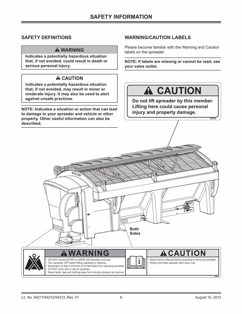
WARNING/CAUTION LABELS
Please become familiar with the Warning and Caution labels on the spreader.
NOTE: If labels are missing or cannot be read, see your sales outlet.
BothSides
CAUTIONIndicates a potentially hazardous situation that, if not avoided, may result in minor or moderate injury. It may also be used to alert against unsafe practices.
WARNINGIndicates a potentially hazardous situation that, if not avoided, could result in death or serious personal injury.
CAUTIONDo not lift spreader by this member.Lifting here could cause personalinjury and property damage.
67272
Lit. No. 94211/94212/94213, Rev. 01 7 August 15, 2013
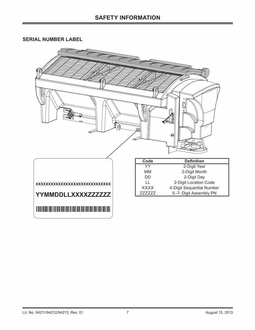
Code Defi nitionYY 2-Digit YearMM 2-Digit MonthDD 2-Digit DayLL 2-Digit Location Code
XXXX 4-Digit Sequential NumberZZZZZZ 5–7- Digit Assembly PN
SERIAL NUMBER LABEL
SAFETY INFORMATION

Lit. No. 94211/94212/94213, Rev. 01 8 August 15, 2013
SAFETY INFORMATION
SAFETY PRECAUTIONS
Improper installation and operation could cause personal injury and/or equipment and property damage. Read and understand labels and the Owner's Manual before installing, operating or making adjustments.
WARNING• Driver to keep bystanders minimum of
25 feet away from operating spreader.• Before working with the spreader, secure all
loose-fi tting clothing and unrestrained hair.• Before operating the spreader, verify all
safety guards are in place.• Before servicing the spreader, wait for
conveyor and spinner to stop.• Do not climb into or ride on spreader.
WARNING Overloading could result in an
accident or damage. Do not exceed GVWR or GAWR ratings as found on the driver-side door cornerpost of
the vehicle. See Loading Section to determine maximum volumes of spreading material.
WARNINGDo not install the control for this product in the deployment path of an air bag. Refer to vehicle manufacturer's manual for air bag deployment area(s).
CAUTIONIf rear directional, CHMSL light or brake stoplights are obstructed by the spreader, the lights shall be relocated, or auxiliary directional or brake stoplights shall be installed.
CAUTIONDuring the hopper spreader installation we recommend the addition of an OSHA compliant Backup Alarm. This alarm is required for OSHA governed employers.
CAUTION• Do not operate a spreader in need of
maintenance.• Before operating the spreader, reassemble
any parts or hardware removed for cleaning or adjusting.
• Before operating the spreader, remove materials such as cleaning rags, brushes, and hand tools from the spreader.
• While operating the spreader, use auxiliary warning lights, except when prohibited by law.
• Tighten all fasteners according to the Torque Chart. Refer to Torque Chart for the recommended torque values.
CAUTIONDisconnect electric and/or hydraulic power and tag out if required before servicing or performing maintenance.
CAUTION DO NOT leave unused material in
hopper. Material can freeze or solidify, causing unit to not work properly. Empty and clean after each use.
NOTE: Lubricate grease fi ttings after each use. Use a good quality multipurpose grease.
PERSONAL SAFETY
• Remove ignition key and put the vehicle in park or in gear to prevent others from starting the vehicle during installation or service.
• Wear only snug-fi tting clothing while working on your vehicle or spreader.
• Do not wear jewelry or a necktie, and secure long hair.
• Wear safety goggles to protect your eyes from battery acid, gasoline, dirt and dust.
• Avoid touching hot surfaces such as the engine, radiator, hoses and exhaust pipes.
• Always have a fi re extinguisher rated BC handy, for fl ammable liquids and electrical fi res.
Lit. No. 94211/94212/94213, Rev. 01 9 August 15, 2013
SAFETY INFORMATION
FIRE AND EXPLOSION
Be careful when using gasoline. Do not use gasoline to clean parts. Store only in approved containers away from sources of heat or fl ame.
CELL PHONES
A driver's fi rst responsibility is the safe operation of the vehicle. The most important thing you can do to prevent a crash is to avoid distractions and pay attention to the road. Wait until it is safe to operate Mobile Communication Equipment such as cell phones, text messaging devices, pagers or two-way radios.
VENTILATION
BATTERY SAFETY
NOISE
Airborne noise emission during use is below 70 dB(A) for the spreader operator.
VIBRATION
Operating spreader vibration does not exceed 2.5 m/s2 to the hand-arm or 0.5 m/s2 to the whole body.
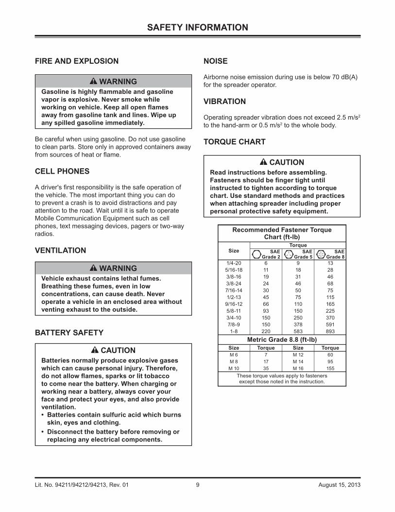
TORQUE CHART
Recommended Fastener TorqueChart (ft-lb)
SizeTorque
SAEGrade 2
SAEGrade 5
SAEGrade 8
1/4-20 6 9 135/16-18 11 18 283/8-16 19 31 463/8-24 24 46 687/16-14 30 50 751/2-13 45 75 115
9/16-12 66 110 1655/8-11 93 150 2253/4-10 150 250 3707/8-9 150 378 5911-8 220 583 893
Metric Grade 8.8 (ft-lb)Size Torque Size TorqueM 6 7 M 12 60M 8 17 M 14 95M 10 35 M 16 155
These torque values apply to fastenersexcept those noted in the instruction.
CAUTIONBatteries normally produce explosive gases which can cause personal injury. Therefore, do not allow fl ames, sparks or lit tobacco to come near the battery. When charging or working near a battery, always cover your face and protect your eyes, and also provide ventilation.• Batteries contain sulfuric acid which burns
skin, eyes and clothing.• Disconnect the battery before removing or
replacing any electrical components.
CAUTIONRead instructions before assembling. Fasteners should be fi nger tight until instructed to tighten according to torque chart. Use standard methods and practices when attaching spreader including proper personal protective safety equipment.
WARNINGVehicle exhaust contains lethal fumes. Breathing these fumes, even in low concentrations, can cause death. Never operate a vehicle in an enclosed area without venting exhaust to the outside.
WARNINGGasoline is highly fl ammable and gasoline vapor is explosive. Never smoke while working on vehicle. Keep all open fl ames away from gasoline tank and lines. Wipe up any spilled gasoline immediately.

Lit. No. 94211/94212/94213, Rev. 01 10 August 15, 2013
LOADING
This Manual covers vehicles which have been recommended for carrying the hopper spreader. Please see your local dealer for proper vehicle applications.
MATERIAL WEIGHTS
Material Density(lb per cubic yd)
Fine Salt – Dry 1,350Coarse Salt – Dry 1,215
Coarse Sand – Dry 2,700Coarse Sand – Wet 3,240
Cinders 1,080
Load Volume
CERTIFICATION
WARNINGOverloading could result in an accident or damage. Do not exceed GVWR or GAWR as found on the driver-side cornerpost of vehicle.
WARNINGNew untitled vehicle installation of a spreader requires National Highway Traffi c Safety Administration altered vehicle certifi cation labeling. Installer to verify that struck load of snow or ice control material does not exceed GVWR or GAWR rating label and complies with FMVSS.
CAUTION Read and adhere to manufacturer's
ice-control material package labeling including Material Safety Data Sheet requirements.
37" (2.5 cu yd)
27" (1.8 cu yd) 27" (1.5 cu yd)
8' Unit 7' Unit

Lit. No. 94211/94212/94213, Rev. 01 11 August 15, 2013
DETERMINING VEHICLE PAYLOAD
1. Install the hopper spreader and optional equipment according to the instructions.
2. Install or attach any other equipment that will be on the vehicle while the hopper spreader will be in use (step bumper, trailer hitch, snowplows, etc.). Fill gas tanks.
3. Obtain the Gross Vehicle Weight Rating (GVWR), Front Gross Axle Weight Rating (FGAWR) and Rear Gross Axle Weight Rating (RGAWR) from the certifi cation label located inside the driver-side door jamb or door.
4. With the occupants in the truck for normal hopper spreader operation, weigh the vehicle to obtain gross vehicle weight (GVW).
WARNINGOverloading could result in an accident or damage. Do not exceed GVWR or GAWR ratings as found on the driver-side door cornerpost of the vehicle. See Loading Section to determine maximum volumes of spreading material.
5. Subtract the GVW from the GVWR to determine the available material payload.
6. Obtain the weight per cubic yard (lb/cu yd) of the desired material. Divide the weight into the payload to determine the maximum volume of material that can be carried.
7. Compare the maximum volume to determine the maximum height of the material in the hopper spreader.
8. Fill the hopper with the material to the calculated height. Reweigh the vehicle with occupants and verify the GVW, Front Gross Axle Weight and Rear Gross Axle Weight are less than the vehicle's ratings.
9. Repeat Steps 7 and 8 for each type of material.
Refer to the "Determining Vehicle Payload" worksheet for an example and worksheet.
LOADING
SPREADER SPECIFICATIONS
Spreader Description
Overall Length
(in)
Empty Weight
(lb)
Capacity Struck (cu yd)
Overall Width
(in)
Overall Height
(in)
Recommended Use
Regular Capacity 7' Hopper Body
Double-Wall Poly108 591 1.5 63 44
3/4–1 ton Pickup Trucks above
8500 lb GVWR8' Hopper Body
w/o CollarDouble-Wall Poly
117 660 1.8 63 443/4–1 ton Pickup
Trucks above 8500 lb GVWR
8' Hopper Bodyw/ Collar
Double-Wall Poly117 734 2.5 63 51
Dump Body –Flatbed

Lit. No. 94211/94212/94213, Rev. 01 12 August 15, 2013
Determining Vehicle Payload Worksheet
Material TypeExample:
Coarse Salt – Dry
Equipment installed whenvehicle was weighed
7' Poly Hopper Spreader
Front Gross Axle Weight Rating(FGAWR) (lb)
Rear Gross Axle Weight Rating(RGAWR) (lb)
Gross Vehicle Weight Rating(GVWR) (lb) 8600
Gross Vehicle Weight (empty)(lb) – 6500
Payload Available(lb) = 2100
Material Density(lb/cu yd) ÷ 1215
Maximum Volume(cu yd) = 1.73
Maximum Height (approximate)(in) 24
Loaded Front Gross Axle Weight
(FGAW) (lb)Loaded Rear Gross Axle
Weight(RGAW) (lb)
Loaded Gross Vehicle Weight(GVW) (lb)
LOADING

Lit. No. 94211/94212/94213, Rev. 01 13 August 15, 2013
NOTE: Periodically throughout the snow and ice control season, verify mounting devices are secure.
1. Remove the chute from the inside of the hopper:
a. Unlatch the rubber straps located at the rear of the lids near the handles.
b. Remove the screens.
c. Remove the screen supports.
d. Remove the chute and replace the screen supports and screens.
e. Close the lids and latch the rubber straps.
2. Remove the tailgate from the truck.
3. Attach the truck mounting bars to the sill brackets:
a. Measure the width between the wheel wells.
b. If needed, cut one or both of the supplied bars to the correct length.
c. Attach them to the sill brackets using the supplied hardware as shown.
MOUNTING THE SPREADER
4. The spreader can be moved into the truck bed either by lifting the spreader by the four molded-in handles located on the corner legs or by sliding the spreader into the truck bed from the ground.
5. To lift the spreader into the truck bed from the ground, stand the spreader up on the feet at the rear of the spreader on top of two spacers at least 2" off the ground. The chute must be removed.
6. Position spreader on its feet at the rear of the truck.
CAUTIONBefore lifting, verify hopper is empty of material. The lifting device must be able to support the spreader's weight as shown in the spreader specifi cations table.
RubberStraps
Spacers
Molded-In Handles(Both Sides)
Attach TruckMounting Bars
Bottom ofSpreader

Lit. No. 94211/94212/94213, Rev. 01 14 August 15, 2013
MOUNTING THE SPREADER
7. Tip the spreader toward the truck until the sill rests on the rear edge of the truck bed.
8. Lift the rear of the spreader and slide it into the truck bed. Two or more people are recommended for this task.
9. Center the spreader in the truck.
10. Remove the cable tie holdling the wire harness to the conveyor chain. Connect the vehicle side harness to the hopper side harness.
11. To assemble the chute to the spreader:
a. Select the height for the chute assembly. The upper chute position (using lower two slots) is typically used for pickup truck installations.
b. Lift the chute onto the feed gate actuator bar and slide it down into place.
c. Align the holes in the hopper body with the threaded inserts in the chute, and install the pins to secure the chute to the hopper body.
d. Connect the spinner motor wiring harness.
12. Install the spacer between the end of the sill and the front of the truck bed as shown. If you do not have a spacer, refer to the Installation Instructions to create one. Failure to install this spacer could result in damage to the spreader.
13. Fasten the spreader to the truck frame using the mounting bars and existing holes and hardware. If there are no holes, refer to the Installation Instructions.
WARNINGSpreader shall be bolted to vehicle frame. Do not rely on the tie-down chains or straps alone to hold spreader in vehicle.
Mounting Bars(Both Sides)
Lit. No. 94211/94212/94213, Rev. 01 15 August 15, 2013
OPERATING THE SPREADER – CAB CONTROL
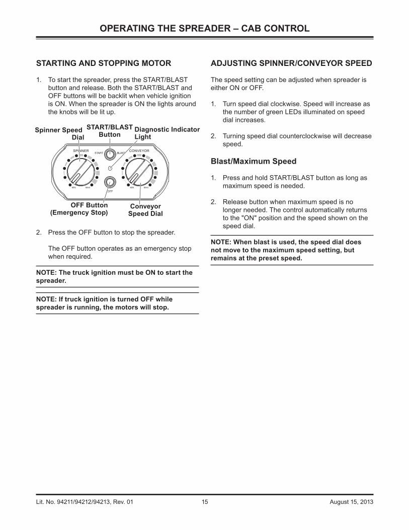
STARTING AND STOPPING MOTOR
1. To start the spreader, press the START/BLAST button and release. Both the START/BLAST and OFF buttons will be backlit when vehicle ignition is ON. When the spreader is ON the lights around the knobs will be lit up.
2. Press the OFF button to stop the spreader.
The OFF button operates as an emergency stop when required.
NOTE: The truck ignition must be ON to start the spreader.
NOTE: If truck ignition is turned OFF while spreader is running, the motors will stop.
START/BLASTButton
OFF Button(Emergency Stop)
Spinner Speed Dial
ConveyorSpeed Dial
Diagnostic IndicatorLight
ADJUSTING SPINNER/CONVEYOR SPEED
The speed setting can be adjusted when spreader is either ON or OFF.
1. Turn speed dial clockwise. Speed will increase as the number of green LEDs illuminated on speed dial increases.
2. Turning speed dial counterclockwise will decrease speed.
Blast/Maximum Speed
1. Press and hold START/BLAST button as long as maximum speed is needed.
2. Release button when maximum speed is no longer needed. The control automatically returns to the "ON" position and the speed shown on the speed dial.
NOTE: When blast is used, the speed dial does not move to the maximum speed setting, but remains at the preset speed.

Lit. No. 94211/94212/94213, Rev. 01 16 August 15, 2013
OPERATING THE SPREADER – CAB CONTROL
DIAGNOSTIC INDICATOR LIGHT AND AUDIO BEEP
The diagnostic indicator light located to the right of the START/BLAST button remains dark unless a problem with the motor or wiring is detected. The light will fl ash in coordination with an audio beep a number of fl ashes/beeps in a row, pause, then repeat. Count the fl ashes/beeps to determine the nature of the malfunction and refer to diagnostic chart below.
NOTE: Always close the lids on the hopper to prevent moisture buildup. Do not let spreader sit idle with material in the hopper for an extended period of time. This can cause material to compact, reduce or stop the fl ow of material and cause permanent hopper body deformation.
# ofFlashes/Beeps Problem Possible Cause
0 No Error –1 No Communication Loss of communication between spreader module and cab control. Vehicle
battery cable is disconnected or faulty.2 Empty Hopper Spreader is empty or material has bridge in the hopper.3 Conveyor Over Current Over 70 amps for up to 3 seconds. Conveyor Chain is stalled.4 No Power Battery fuse is blown or vehicle battery cable is disconnected or faulty.
5,8 Over Temp Motor is OFF due to spreader module overheating from high-current draw over a long period of time.
6 Battery Saver Reduced spreader performance due to vehicle voltage drop. Spreader will function at reduced output until vehicle voltage increases.
7 Spinner Over Current Over 32 amps for up to 3 seconds. Spinner is stalled.9 Sander Reset Module came out of reset. Momentary loss of power. Restart unit, check
power wiring.10 Cool Down If the unit gets more than 5 faults with each fault starting within 60 seconds
from the last, it will not start for 60 seconds from the last fault to allow the unit to cool.
11 Low Battery Low battery voltage or poor electrical connection of vehicle battery cable.
Lit. No. 94211/94212/94213, Rev. 01 17 August 15, 2013
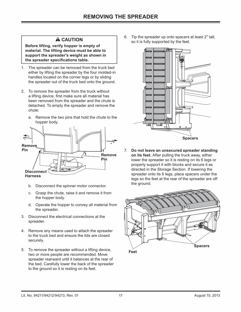
6. Tip the spreader up onto spacers at least 2" tall, so it is fully supported by the feet.
7. Do not leave an unsecured spreader standing on its feet. After pulling the truck away, either lower the spreader so it is resting on its 6 legs or properly support it with blocks and secure it as directed in the Storage Section. If lowering the spreader onto its 6 legs, place spacers under the legs so the feet at the rear of the spreader are off the ground.
Spacers
SpacersFeet
REMOVING THE SPREADER
1. The spreader can be removed from the truck bed either by lifting the spreader by the four molded-in handles located on the corner legs or by sliding the spreader out of the truck bed onto the ground.
2. To remove the spreader from the truck without a lifting device, fi rst make sure all material has been removed from the spreader and the chute is detached. To empty the spreader and remove the chute:
a. Remove the two pins that hold the chute to the hopper body.
b. Disconnect the spinner motor connector.
c. Grasp the chute, raise it and remove it from the hopper body.
d. Operate the hopper to convey all material from the spreader.
3. Disconnect the electrical connections at the spreader.
4. Remove any means used to attach the spreader to the truck bed and ensure the lids are closed securely.
5. To remove the spreader without a lifting device, two or more people are recommended. Move spreader rearward until it balances at the rear of the bed. Carefully lower the back of the spreader to the ground so it is resting on its feet.
Disconnect Harness
Remove Pin
Remove Pin
CAUTIONBefore lifting, verify hopper is empty of material. The lifting device must be able to support the spreader's weight as shown in the spreader specifi cations table.

Lit. No. 94211/94212/94213, Rev. 01 18 August 15, 2013
CHAIN TENSION
NOTE: Overtightening the chain may result in damage to the motor or gearbox bearing.
To adjust the chain tension:
1. Loosen the bolts that hold the drive motor.
2. Slide the motor to increase or decrease the chain tension.
3. After adjusting the motor, tighten the bolts. The chain should defl ect 1/4" between the sprockets.
GREASE FITTINGS
To keep your spreader running smoothly, observe the following recommendations:
• Lubricate grease fi ttings after each use and at the end of each season.
MAINTENANCE
CAUTIONDisconnect electric power at spreader electrical wiring harness connection and tag out if required before servicing or performing maintenance.
Grease after each use with a goodquality multipurpose grease.
Motor
Gearbox Input Shaft
Approx. 1/4"

Lit. No. 94211/94212/94213, Rev. 01 19 August 15, 2013
CONVEYOR PINTLE CHAIN TENSION
1. Periodically check the conveyor chain tension. The spreader should be out of the vehicle. To check the tension, measure in 20"–24" from the rear edge of the sills. Push up on the chain with your hand. The conveyor chain should lift up 1"–3" off the conveyor chain guide.
2. If the slack is greater than 3", loosen the two bearing mounting bolts on each side of the conveyor idle roller on cab end of hopper.
3. Loosen the jam nut on one of the take-up bolts, then tighten (clockwise) the take-up bolt one full revolution. Repeat evenly on the other side.
AFTER EACH USE
• Wash out the hopper and rinse off all external surfaces.
• Clean out any trapped/frozen material from between the pintle chain and the vehicle bed surface.
• Apply dielectric grease on all electrical connections to prevent corrosion at the beginning and end of the season and after each use.
• Lubricate all grease fi ttings with good quality multipurpose grease.
MAINTENANCE
STORAGE
The spreader can be stored on end (on its feet) for storage; however, steps must be taken to properly support it with blocks and secure it.
1. Back the truck near a wall, fence or other permanent structure so that there is enough room to remove the spreader but the spreader will be against the structure when it is taken out of the truck.
2. Remove the spreader from the truck following the instructions in this manual.
3. Add blocks supporting the sides of the hopper body and conveyor, as shown.
JamNut
IdlerTake-Up
Bolt
BearingMounting
Bolts
Support sides and conveyor with blocks.
Lit. No. 94211/94212/94213, Rev. 01 20 August 15, 2013
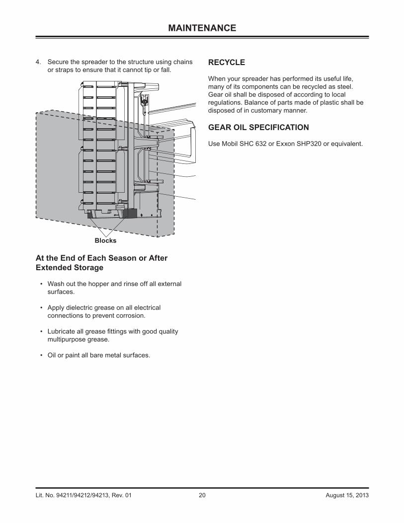
4. Secure the spreader to the structure using chains or straps to ensure that it cannot tip or fall.
At the End of Each Season or After Extended Storage
• Wash out the hopper and rinse off all external surfaces.
• Apply dielectric grease on all electrical connections to prevent corrosion.
• Lubricate all grease fi ttings with good quality multipurpose grease.
• Oil or paint all bare metal surfaces.
RECYCLE
When your spreader has performed its useful life, many of its components can be recycled as steel. Gear oil shall be disposed of according to local regulations. Balance of parts made of plastic shall be disposed of in customary manner.
GEAR OIL SPECIFICATION
Use Mobil SHC 632 or Exxon SHP320 or equivalent.
MAINTENANCE
Blocks
Lit. No. 94211/94212/94213, Rev. 01 21 August 15, 2013
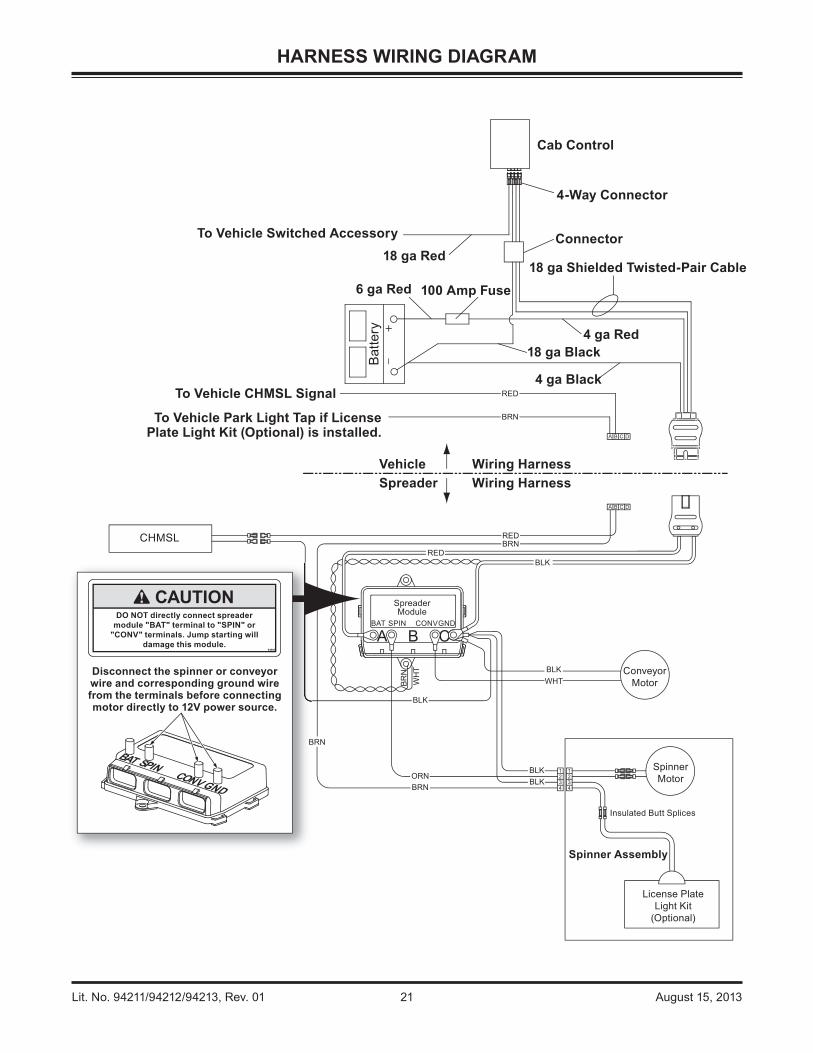
HARNESS WIRING DIAGRAM
A DCB
A DCB
CHMSL
SpinnerMotor
ConveyorMotor
Spinner Assembly
License PlateLight Kit
(Optional)
Insulated Butt Splices
+
_
Cab Control
4-Way Connector
Connector
18 ga Shielded Twisted-Pair Cable
4 ga Red18 ga Black
4 ga Black
Wiring HarnessWiring Harness
VehicleSpreader
To Vehicle CHMSL Signal
To Vehicle Park Light Tap if LicensePlate Light Kit (Optional) is installed.
Bat
tery
100 Amp Fuse6 ga Red
18 ga RedTo Vehicle Switched Accessory
Disconnect the spinner or conveyorwire and corresponding ground wirefrom the terminals before connectingmotor directly to 12V power source.
ORNBRN
BRN
BRN
BLK
BLKWHT
BLKBLK
BLKRED
RED
BRN
REDB
RN
WH
T
Lit. No. 94211/94212/94213, Rev. 01 22 August 15, 2013
TROUBLESHOOTING GUIDE
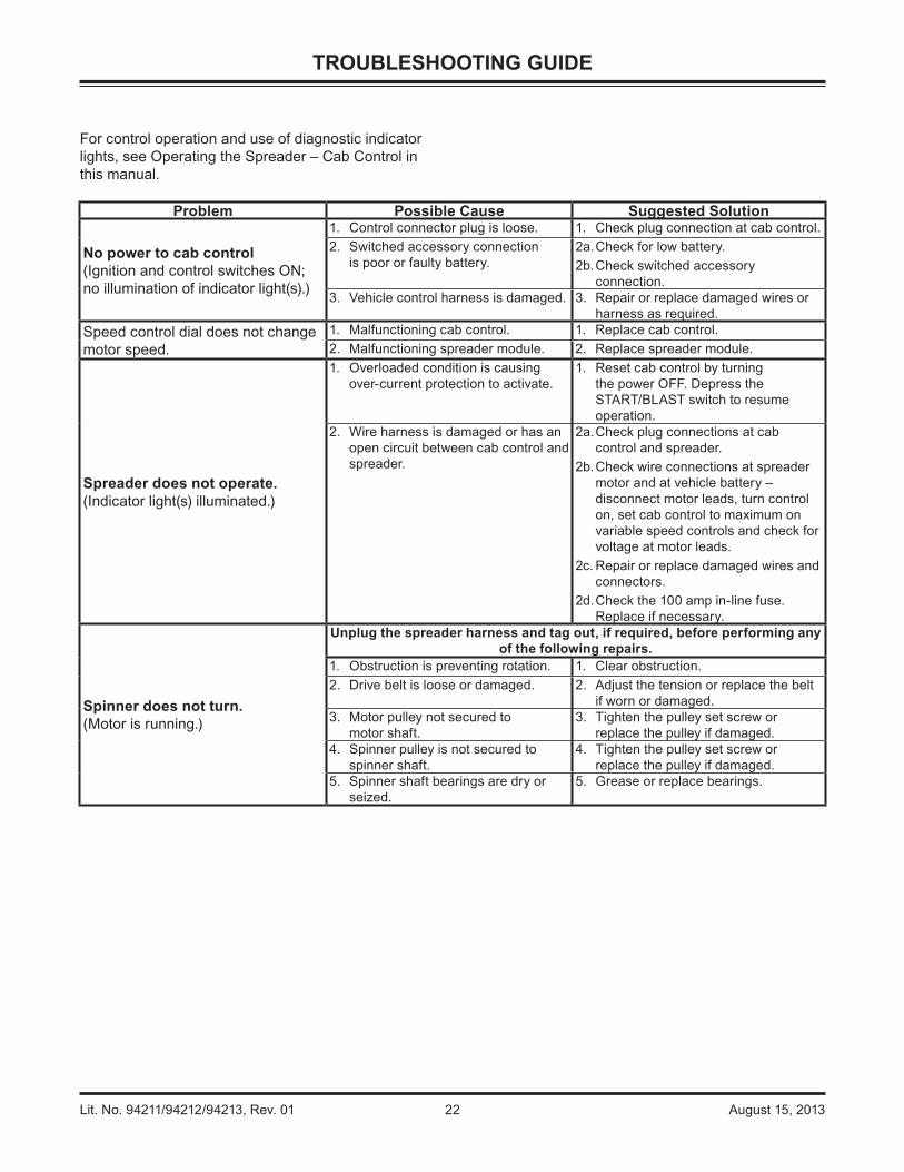
For control operation and use of diagnostic indicator lights, see Operating the Spreader – Cab Control in this manual.
Problem Possible Cause Suggested Solution
No power to cab control(Ignition and control switches ON; no illumination of indicator light(s).)
1. Control connector plug is loose. 1. Check plug connection at cab control.2. Switched accessory connection
is poor or faulty battery.2a. Check for low battery.2b. Check switched accessory
connection.3. Vehicle control harness is damaged. 3. Repair or replace damaged wires or
harness as required.Speed control dial does not change motor speed.
1. Malfunctioning cab control. 1. Replace cab control.2. Malfunctioning spreader module. 2. Replace spreader module.
Spreader does not operate.(Indicator light(s) illuminated.)
1. Overloaded condition is causing over-current protection to activate.
1. Reset cab control by turning the power OFF. Depress the START/BLAST switch to resume operation.
2. Wire harness is damaged or has an open circuit between cab control and spreader.
2a. Check plug connections at cab control and spreader.
2b. Check wire connections at spreader motor and at vehicle battery – disconnect motor leads, turn control on, set cab control to maximum on variable speed controls and check for voltage at motor leads.
2c. Repair or replace damaged wires and connectors.
2d. Check the 100 amp in-line fuse. Replace if necessary.
Spinner does not turn.(Motor is running.)
Unplug the spreader harness and tag out, if required, before performing any of the following repairs.
1. Obstruction is preventing rotation. 1. Clear obstruction.2. Drive belt is loose or damaged. 2. Adjust the tension or replace the belt
if worn or damaged.3. Motor pulley not secured to
motor shaft.3. Tighten the pulley set screw or
replace the pulley if damaged.4. Spinner pulley is not secured to
spinner shaft.4. Tighten the pulley set screw or
replace the pulley if damaged.5. Spinner shaft bearings are dry or
seized.5. Grease or replace bearings.

Lit. No. 94211/94212/94213, Rev. 01 23 August 15, 2013
TROUBLESHOOTING GUIDE
Problem Possible Cause Suggested Solution
Conveyor chain not moving(Spinner is turning.)
Unplug the spreader harness and tag out, if required, before performing any of the following repairs.
1. Obstruction is preventing rotation. 1. Clear obstruction.2. Sprocket is not secured to motor
shaft.2. Replace set screw if missing or
damaged. Replace sprocket if damaged.
3. Sprocket is not secured to gearbox shaft.
3. Replace damaged or missing key. Replace sprocket if damaged.
4. Gearbox is damaged. 4. Replace gearbox if output shaft does not turn when input shaft turns.
5. Conveyor sprockets are not secured to shafts.
5. Replace missing cap screws and nuts. Replace shafts or sprockets if damaged.
6. Conveyor pintle chain is loose or damaged.
6. Adjust pintle chain tension. Replace pintle chain if damaged.
7. Conveyor pintle chain is not aligned. 7. Align pintle chain to ride centered on rollers.
8. Conveyor pintle chain shaft bearings are seized or otherwise damaged.
8. Grease or replace bearings.
Material in hopper does not fl ow.(Conveyor pintle chain and spinner are moving.)
Unplug the spreader harness and tag out, if required, before performing any of the following repairs.
1. Feed gate is closed. 1. Open feed gate fully, then adjust to desired opening size.
2. Obstruction in hopper. 2. Clear obstruction.3. Material bridged. 3. Clear the bridge.

Lit. No. 94212, Rev. 01 August 15, 2013
Copyright © 2013 Douglas Dynamics, LLC. All rights reserved. This material may not be reproduced or copied, in whole or in part, in any printed, mechanical, electronic, fi lm or other distribution and storage media, without the written consent of Fisher Engineering. Authorization to photocopy items for internal or personal use by Fisher Engineering outlets or spreader owner is granted.
Fisher Engineering reserves the right under its product improvement policy to change construction or design details and furnish equipment when so altered without reference to illustrations or specifi cations used. Fisher Engineering or the vehicle manufacturer may require or recommend optional equipment for spreaders. Do not exceed vehicle ratings with a spreader. This product is manufactured under the following U.S. patents: 7,400,058; 7,737,576. Fisher Engineering offers a limited warranty for all spreaders and accessories. See separately printed page for this important information. The following are registered (®) or unregistered (™) trademarks of Douglas Dynamics, LLC: FISHER®, POLY-CASTER™.
Printed in U.S.A.
A DIVISION OF FISHER, LLC.
Fisher Engineering50 Gordon DriveRockland, ME 04841-2139www.fi sherplows.com
This product conforms to EU Machinery Directive 2006/42/EC and Directive 2011/65/EC (RoHS2).