polaroid , flm323b
DESCRIPTION
Full Schematics, parts, diagrams.TRANSCRIPT
2006 LCD Models FLM-2632, FLM-2632M, FLM-2634B, FLM-3232, FLM-3232M, FLM-323B, FLM-3234B, FLM-3732, FLM-3732M, FLM-373B, FLM-3734B, FLX-374
SERVICE MANUAL
Bezel covers vary by model 20070411
Important Service and Safety Information
Prior to using this service manual, please ensure that you have carefully followed all the procedures outlined in the user's manual for this product.
(1) Read all of these instructions.
(2) Save these instructions.
(3) Follow all warnings and instructions marked on the product.
(4) Unplug this product from the wall outlet before cleaning. Do not use liquid cleaners or aerosol cleaners; use a damp cloth for cleaning.
(5) Do not use this product near water.
(6) Do not place this product on an unstable cart, stand or table. The product may fall, causing serious damage to the product.
(7) Slots and openings in the cabinet and the back or bottom are provided for ventilation, to ensure reliable operation of the product and to protect it from overheating, those openings must not be blocked or covered. The openings should never be blocked by placing the product on a bed, sofa, rug, or other similar surface. This product should not be placed in a built-in installation unless proper ventilation is provided.
(8) This product should be operated from the type of power source indicated on the marketing label. If you are not sure of the type of power available, consult your dealer or local power company.
(9) This product is equipped with a 3-wire grounding type plug, a plug having a third (grounding) pin. This plug will only fit into a grounding-type power outlet. This is a safety feature, if you are unable to insert the plug into the outlet, contact your electrician to replace your obsolete outlet. Do not ignore the purpose of the grounding-type plug.
(10) Do not allow anything to rest on the power cord. Do not locate this product where people will walk on the cord.
(11) If an extension cord is used with this product, make sure that the total of the ampere ratings on the product plugged into the extension cord does not exceed 15 ampere.
(12) Never push objects of any kind into this product through cabinet slots as they may touch dangerous voltage points or short out parts that could result in a risk of fire or electric shock. Never spill liquid of any kind on the product.
(13) Do not attempt to service this product yourself, as opening or removing covers may expose you to dangerous voltage points or other risks. Refer all servicing to service personnel.
(14) Unplug this product from the wall outlet and refer servicing to qualified service personnel under the following conditions: (0)
a. When the power cord or plug is damaged or frayed.
b. If liquid has been spilled into the product.
c. If the product has been exposed to rain or water.
d. If the product does not operate normally, when the operating instructions are followed. Adjust only those controls that are covered by the operating instructions since improper adjustment of other controls may result in damage and will often require extensive work by a qualified technician to restore the product to normal operation.
e. If the product has been dropped or the cabinet has been damaged.
f. If the product exhibits a distinct change in performance, indicating a need for service. .
2
Important Service and Safety Information
Service work should be performed only by qualified service technicians familiar with all safety checks and these service guidelines: ELECTRIC SHOCK HAZARD
Always disconnect AC power before servicing! Never modify any circuit! Never insert any objects into the holes in the TV case!
ELECTROSTATIC DISCHARGE (ESD) Components inside an LCD or plasma TV are sensitive to static electricity. Before servicing the TV, follow these guidelines:
• Avoid static-causing surfaces such as carpeted floors, plastic, and packing foam. • Remove replacement components from their antistatic bags only when you are ready to use them. Do
not lay components on the outside of antistatic bags because only the inside of the bags provide electrostatic protection.
• Always hold components by their edges. Avoid touching the edge connectors. Never slide components over any surface.
• Wear a grounding wrist strap (available at most electronics stores) and attach it to a bare metal part of your workbench or other grounded connection.
• Touch a bare metal surface on your workbench or other grounded object before touching any components.
PRECAUTIONS FOR USING LEAD-FREE SOLDER
Components within this television use lead-free solder (Sn-Ag-Cu). Look at the markings on board and components within the television to determine the correct solder type and match to the table below:
5 LEAD-FREE (Pb-Free) CATEGORIES
The following categories are meant to describe the Pb-free 2nd level interconnect terminal finish, component material, and/or the solder paste/solder used in board assembly:
e1 - SnAgCu (shall not be included in category e2) e2 - Sn alloys with no Bi or Zn excluding SnAgCu e3 - Sn e4 - Precious metal (e.g., Ag, Au, NiPd, NiPdAu) (no Sn) e5 - SnZn, SnZnx (no Bi) e6 - contains Bi e7 - low temperature solder (≤ 150 °C) containing Indium (no Bi) e0, e8, e9 symbols are unassigned at this time.
When repairing components soldered with lead-free solder, ONLY use lead-free solder that matches the symbol on the component. Using conventional lead solder may lead to damage or a short, which could result in fire, electric shock, or other hazards. Because the melting point of lead-free solder is higher than conventional lead solder, observe the following guidelines when soldering with lead-free solder:
3
(1) Always use a dedicated soldering bit for different types of solder. If a different type of solder comes in contact with a lead-free solder bit, subsequent solder joints will no longer be lead free. Always clean the soldering bit after every use.
(2) Keep the soldering bit in contact with the just long enough to confirm a good solder joint. Leaving the bit in contact with parts for an extended period may damage the components.
(3) Because lead-free solder contains a higher concentration of tin, the tip of the soldering bit may be easily corroded or damaged. Do not leave the bit powered on for extended periods. When the tip of the soldering bit is blackened during use, clean the bit with steel wool or fine sandpaper. (0)
NOTICE ABOUT REPLACEMENT PARTS
Many electrical and mechanical parts within LCD or plasma televisions are chosen for their specific safety characteristics within the overall system. Replacing individual parts with components rated for higher voltage or wattage can be dangerous!
Replacement parts must always be identical to those originally used in the television. Unauthorized substitute parts may result in fire, electric shock, or other hazards.
4
5
Table of Contents
1. Operation ....................................................................................................................................... 6 2. Troubleshooting / Flow Charts ....................................................................................................... 14 3. Polaroid Display Cell Defect Specification ........................................................................................ 18 4. Before Returning This Product to the User ...................................................................................... 19 5. Disassembly Procedure.................................................................................................................. 20
Rear Cover Removal ................................................................................................................ 21 Rear Cabinet Cover LCD Panel and Front Bezel .......................................................................... 23 A/V Board Removal and Replacement ....................................................................................... 29 IR Board Removal and Replacement ......................................................................................... 30 Front/Side Control Buttons Removal and Replacement ............................................................... 31
6. Spare Parts Lists – FLM-Series 26, 32, 37 ....................................................................................... 32 7. Exploded View Diagram................................................................................................................. 39 8. Block Diagram – FLM-Series 26, 32, 37........................................................................................... 42 9. Schematics ................................................................................................................................... 43 10. PCB Layout Diagrams .................................................................................................................... 51
Model Specifications are located in User Manual. Go to polaroid.com to obtain User Manual.

6
1. Operation
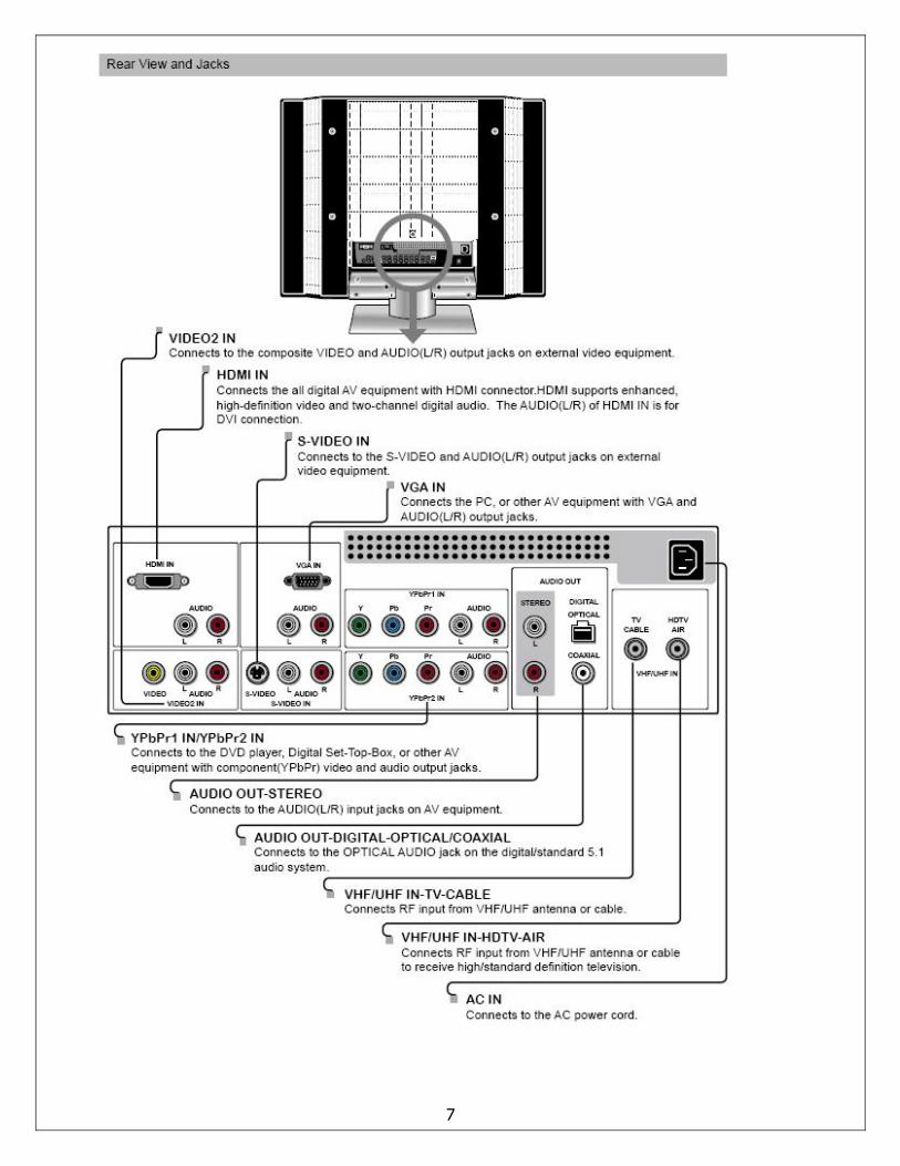
7
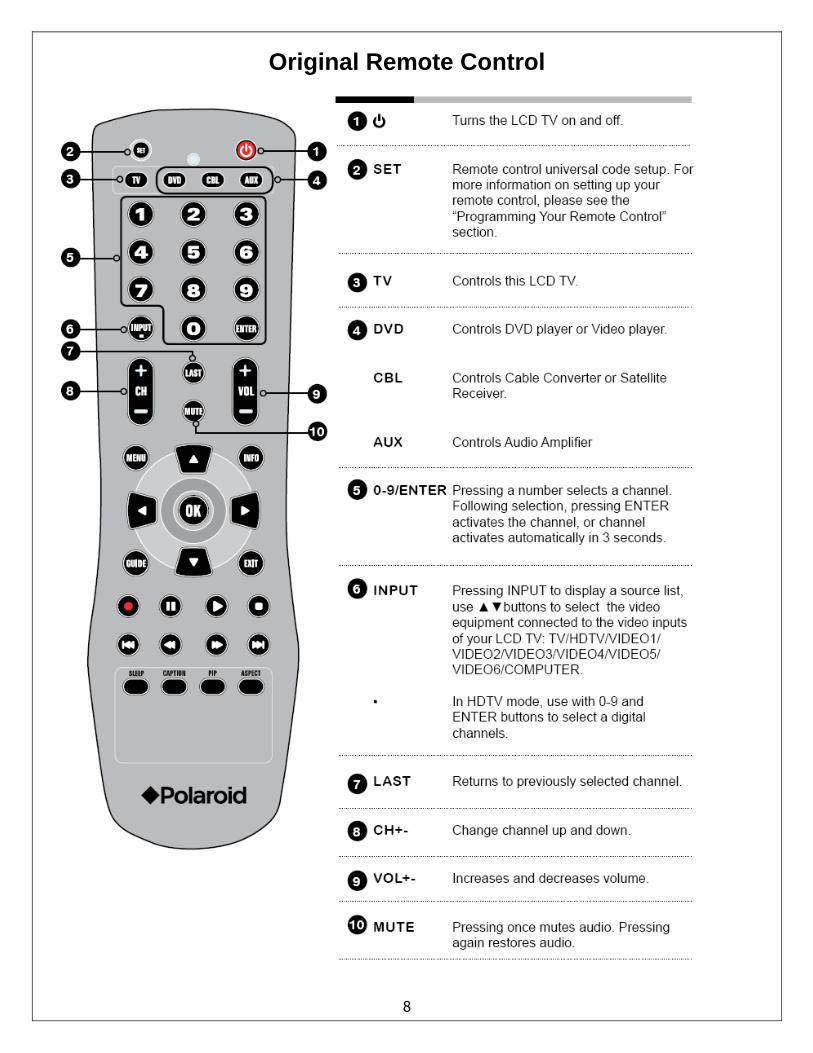
Original Remote Control
8
9
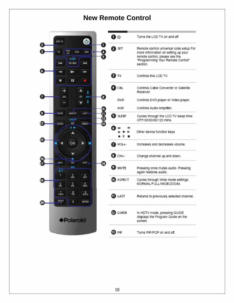
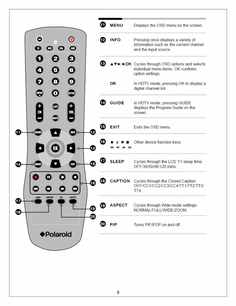
New Remote Control
10
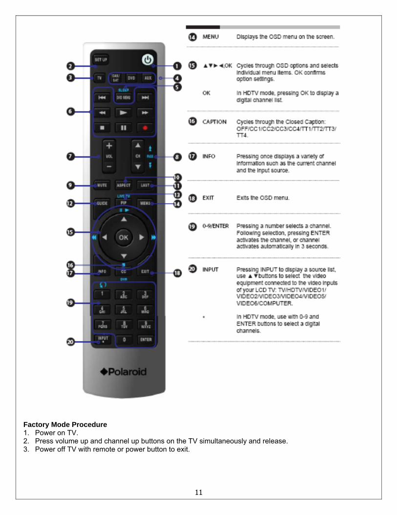
Factory Mode Procedure 1. Power on TV. 2. Press volume up and channel up buttons on the TV simultaneously and release. 3. Power off TV with remote or power button to exit.
11
12
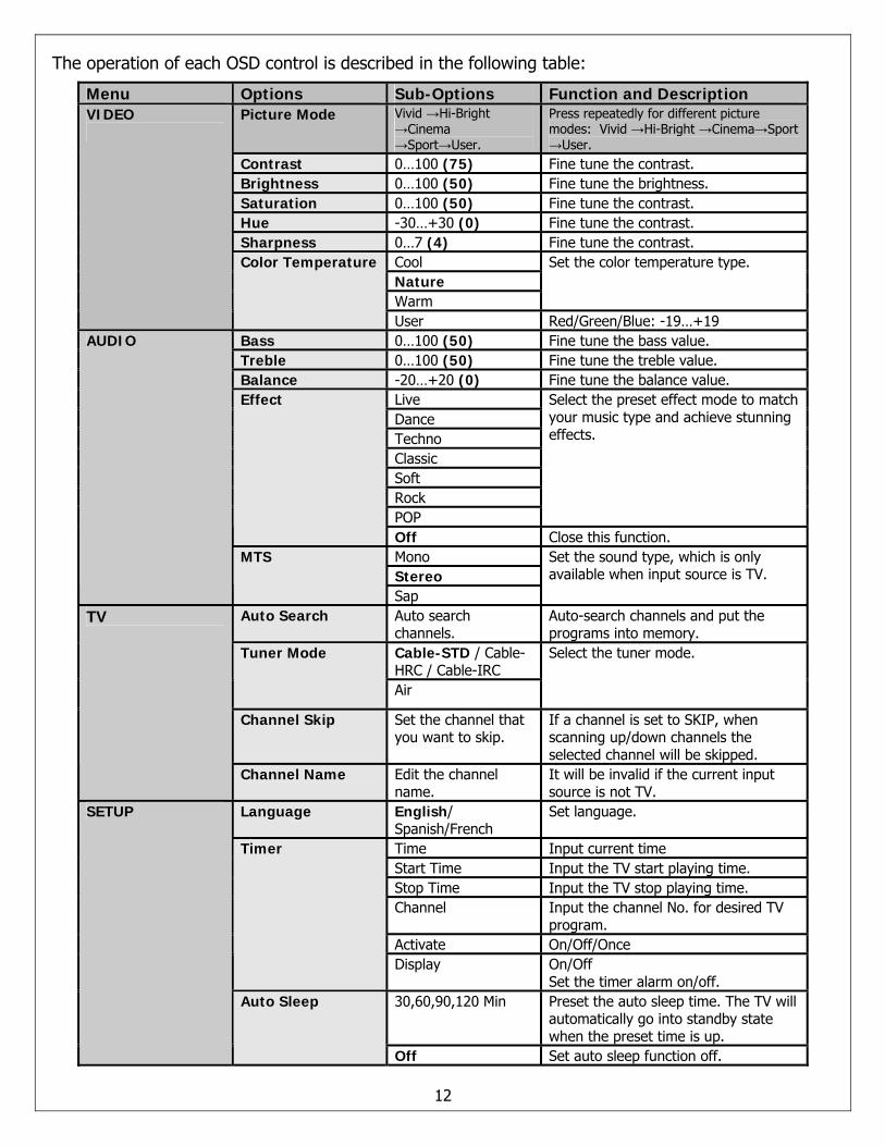
The operation of each OSD control is described in the following table:
Menu Options Sub-Options Function and Description Picture Mode Vivid →Hi-Bright
→Cinema →Sport→User.
Press repeatedly for different picture modes: Vivid →Hi-Bright →Cinema→Sport →User.
Contrast 0…100 (75) Fine tune the contrast. Brightness 0…100 (50) Fine tune the brightness. Saturation 0…100 (50) Fine tune the contrast. Hue -30…+30 (0) Fine tune the contrast. Sharpness 0…7 (4) Fine tune the contrast.
Cool Nature Warm
Set the color temperature type.
VIDEO
Color Temperature
User Red/Green/Blue: -19…+19 Bass 0…100 (50) Fine tune the bass value. Treble 0…100 (50) Fine tune the treble value. Balance -20…+20 (0) Fine tune the balance value.
Live Dance Techno Classic Soft Rock POP
Select the preset effect mode to match your music type and achieve stunning effects.
Effect
Off Close this function. Mono Stereo
AUDIO
MTS
Sap
Set the sound type, which is only available when input source is TV.
Auto Search Auto search channels.
Auto-search channels and put the programs into memory.
Cable-STD / Cable-HRC / Cable-IRC
Tuner Mode
Air
Select the tuner mode.
Channel Skip Set the channel that you want to skip.
If a channel is set to SKIP, when scanning up/down channels the selected channel will be skipped.
TV
Channel Name Edit the channel name.
It will be invalid if the current input source is not TV.
Language English/ Spanish/French
Set language.
Time Input current time Start Time Input the TV start playing time. Stop Time Input the TV stop playing time. Channel Input the channel No. for desired TV
program. Activate On/Off/Once
Timer
Display On/Off Set the timer alarm on/off.
30,60,90,120 Min Preset the auto sleep time. The TV will automatically go into standby state when the preset time is up.
SETUP
Auto Sleep
Off Set auto sleep function off.
13
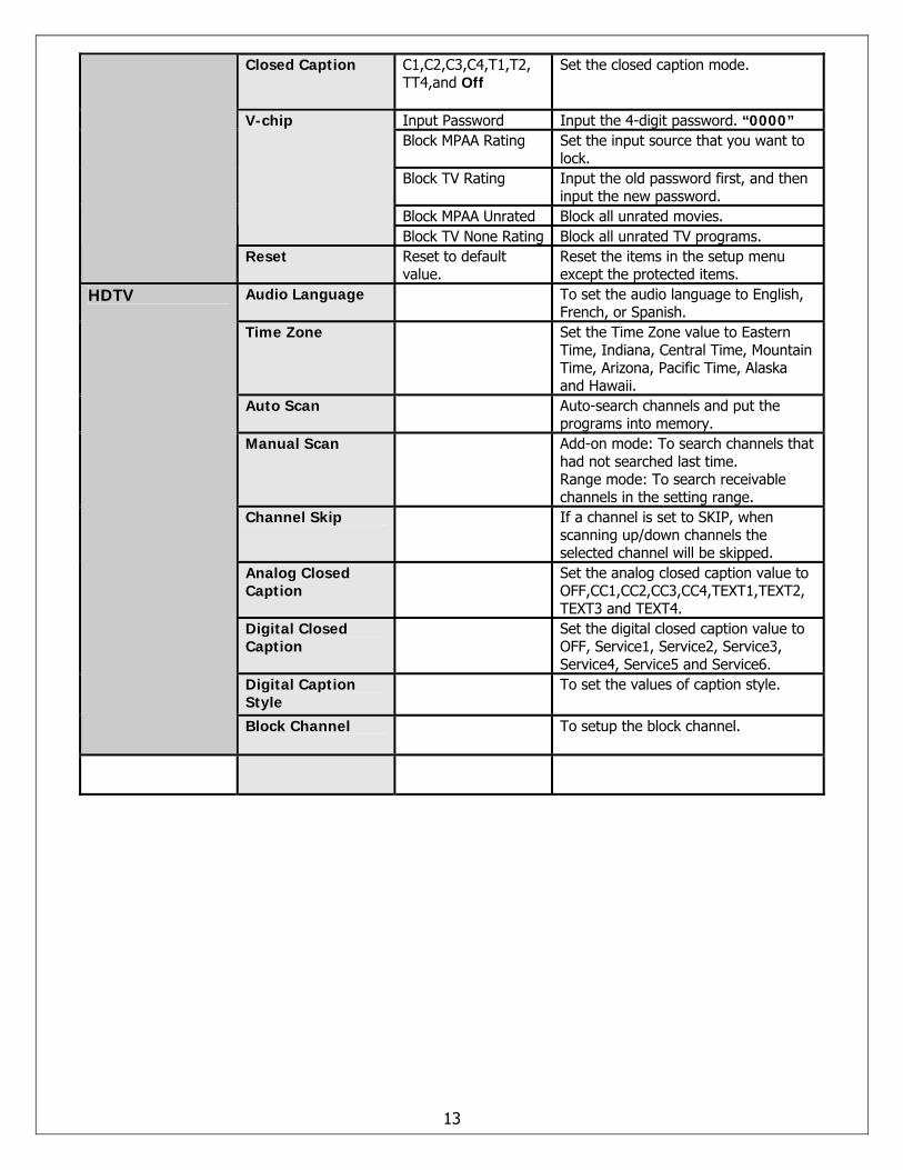
Closed Caption C1,C2,C3,C4,T1,T2, TT4,and Off
Set the closed caption mode.
Input Password Input the 4-digit password. “0000” Block MPAA Rating Set the input source that you want to
lock. Block TV Rating Input the old password first, and then
input the new password. Block MPAA Unrated Block all unrated movies.
V-chip
Block TV None Rating Block all unrated TV programs. Reset Reset to default
value. Reset the items in the setup menu except the protected items.
Audio Language To set the audio language to English, French, or Spanish.
Time Zone Set the Time Zone value to Eastern Time, Indiana, Central Time, Mountain Time, Arizona, Pacific Time, Alaska and Hawaii.
Auto Scan Auto-search channels and put the programs into memory.
Manual Scan Add-on mode: To search channels that had not searched last time. Range mode: To search receivable channels in the setting range.
Channel Skip If a channel is set to SKIP, when scanning up/down channels the selected channel will be skipped.
Analog Closed Caption
Set the analog closed caption value to OFF,CC1,CC2,CC3,CC4,TEXT1,TEXT2, TEXT3 and TEXT4.
Digital Closed Caption
Set the digital closed caption value to OFF, Service1, Service2, Service3, Service4, Service5 and Service6.
Digital Caption Style
To set the values of caption style.
HDTV
Block Channel To setup the block channel.
2. Troubleshooting / Flow Charts
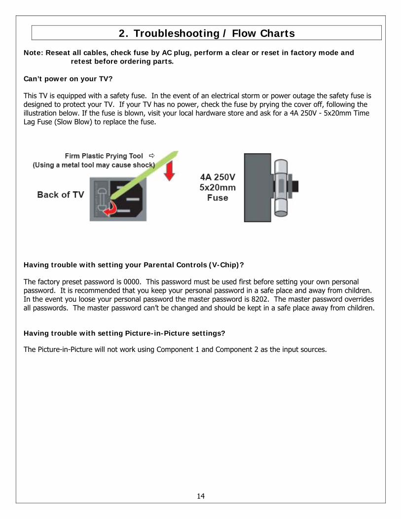
Note: Reseat all cables, check fuse by AC plug, perform a clear or reset in factory mode and retest before ordering parts.
Can’t power on your TV? This TV is equipped with a safety fuse. In the event of an electrical storm or power outage the safety fuse is designed to protect your TV. If your TV has no power, check the fuse by prying the cover off, following the illustration below. If the fuse is blown, visit your local hardware store and ask for a 4A 250V - 5x20mm Time Lag Fuse (Slow Blow) to replace the fuse.
Having trouble with setting your Parental Controls (V-Chip)? The factory preset password is 0000. This password must be used first before setting your own personal password. It is recommended that you keep your personal password in a safe place and away from children. In the event you loose your personal password the master password is 8202. The master password overrides all passwords. The master password can’t be changed and should be kept in a safe place away from children. Having trouble with setting Picture-in-Picture settings? The Picture-in-Picture will not work using Component 1 and Component 2 as the input sources.
14
15
16
17
18
3. Polaroid Display Cell Defect Specification
In some cases, a panel may have defective cells that cannot be controlled. These defective cells can be categorized into two types;
(1) Non-lighting or dark cell defect: defect in which the cell is always off(2) Non-extinguishing or bright cell defect: defect in which the cell is always on
The Polaroid Display Cell Defect Specifications below define the allowed limits for display cell defects and are used as the criteria in determining whether an LCD panel is replaced. 7 or more defective pixels across the entire LCD screen Polaroid will repair (replace LCD panel) or replace the TV.
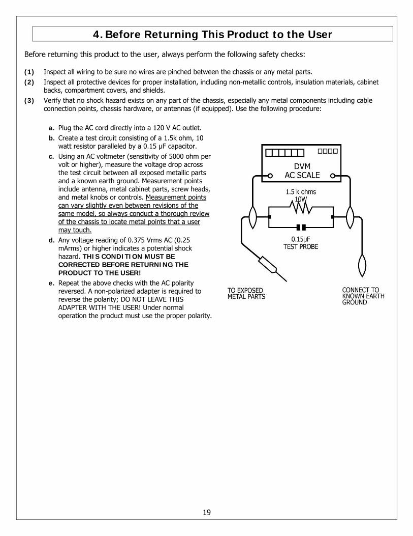
4. Before Returning This Product to the User
Before returning this product to the user, always perform the following safety checks: (1) Inspect all wiring to be sure no wires are pinched between the chassis or any metal parts. (2) Inspect all protective devices for proper installation, including non-metallic controls, insulation materials, cabinet
backs, compartment covers, and shields. (3) Verify that no shock hazard exists on any part of the chassis, especially any metal components including cable
connection points, chassis hardware, or antennas (if equipped). Use the following procedure:
a. Plug the AC cord directly into a 120 V AC outlet. b. Create a test circuit consisting of a 1.5k ohm, 10
watt resistor paralleled by a 0.15 µF capacitor. c. Using an AC voltmeter (sensitivity of 5000 ohm per
volt or higher), measure the voltage drop across the test circuit between all exposed metallic parts and a known earth ground. Measurement points include antenna, metal cabinet parts, screw heads, and metal knobs or controls. Measurement points can vary slightly even between revisions of the same model, so always conduct a thorough review of the chassis to locate metal points that a user may touch.
d. Any voltage reading of 0.375 Vrms AC (0.25 mArms) or higher indicates a potential shock hazard. THIS CONDITION MUST BE CORRECTED BEFORE RETURNING THE PRODUCT TO THE USER!
e. Repeat the above checks with the AC polarity reversed. A non-polarized adapter is required to reverse the polarity; DO NOT LEAVE THIS ADAPTER WITH THE USER! Under normal operation the product must use the proper polarity.
19
5. Disassembly Procedure
Note: Before disassembly of any part the TV, make sure the power is OFF, and the power cord is removed from the wall outlet. Allow time for power within all system boards to discharge before you begin disassembly. Never insert any objects into the vent holes in the TV case.
Note: Before returning this product to the end user, you must follow the steps outlined in the section, Before Returning This Product to the User, on page 19. This procedure ensures that the chassis will not cause electric shock.
When servicing an LCD or plasma TV, always observe the following safety guidelines:
• Wear a grounding (ESD) wrist strap, and use a grounded or dissipative work mat. • Use a stable and strong work surface that is large enough to hold components you might remove. • When removing components that are attached with a cable, unplug the cable before removing the
screws to avoid damaging the cable. • Use a magnetized screwdriver for removing screws. • To help keep track of screws, place each component’s screws next to the component on your work
surface. ELECTROSTATIC DISCHARGE (ESD) Components inside an LCD or plasma TV are sensitive to static electricity. Before servicing the TV, follow these guidelines:
• Avoid static-causing surfaces such as carpeted floors, plastic, and packing foam. • Remove replacement components from their antistatic bags only when you are ready to use them. Do
not lay components on the outside of antistatic bags because only the inside of the bags provide electrostatic protection.
• Always hold components by their edges. Avoid touching the edge connectors. Never slide components over any surface.
• Wear a grounding wrist strap (available at most electronics stores) and attach it to a bare metal part of your workbench or other grounded connection.
• Touch a bare metal surface on your workbench or other grounded object before touching any components.
20
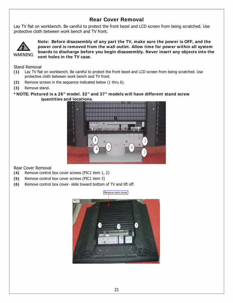
Rear Cover Removal Lay TV flat on workbench. Be careful to protect the front bezel and LCD screen from being scratched. Use protective cloth between work bench and TV front.
Note: Before disassembly of any part the TV, make sure the power is OFF, and the power cord is removed from the wall outlet. Allow time for power within all system boards to discharge before you begin disassembly. Never insert any objects into the vent holes in the TV case.
Stand Removal (1) Lay TV flat on workbench. Be careful to protect the front bezel and LCD screen from being scratched. Use
protective cloth between work bench and TV front. (2) Remove screws in the sequence indicated below (1 thru 6). (3) Remove stand.
*NOTE: Pictured is a 26” model. 32” and 37” models will have different stand screw quantities and locations.
Rear Cover Removal (4) Remove control box cover screws (PIC1 item 1, 2) (5) Remove control box cover screws (PIC1 item 3) (6) Remove control box cover- slide toward bottom of TV and lift off.
21
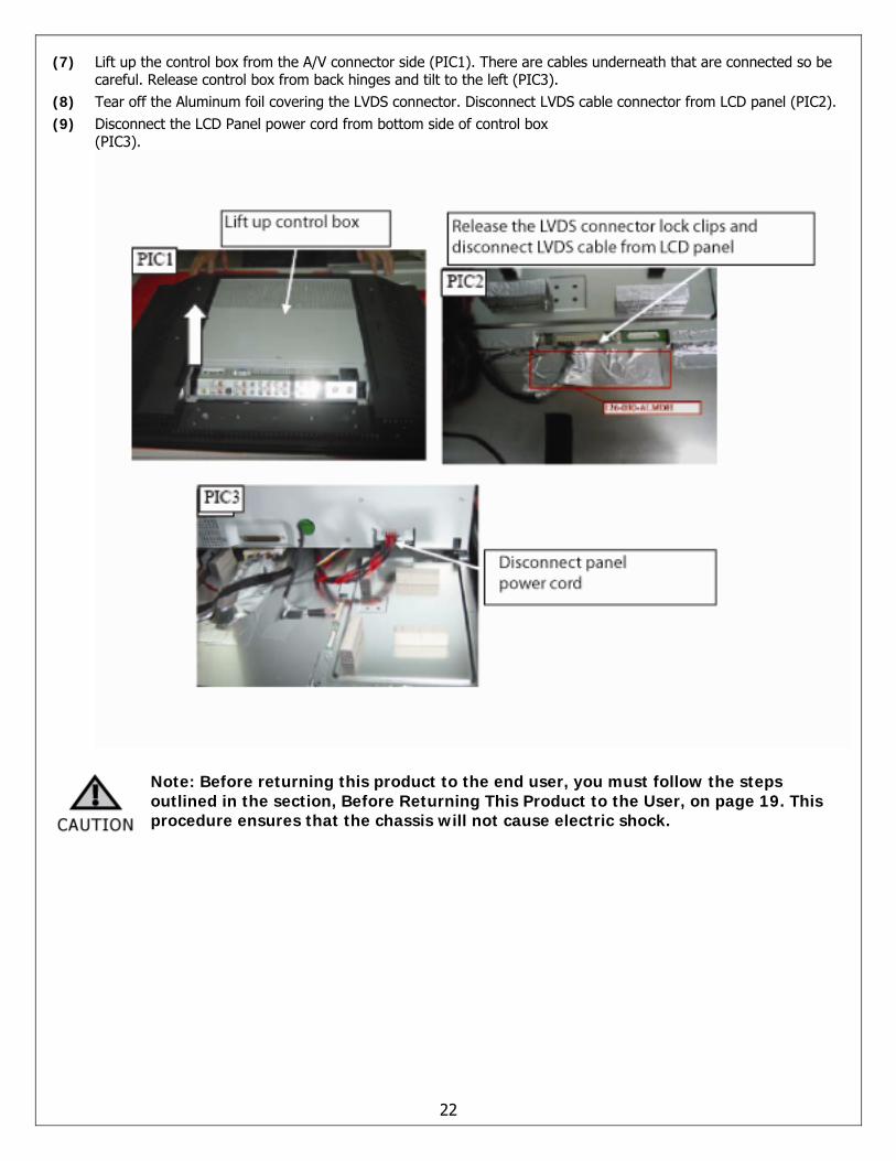
(7) Lift up the control box from the A/V connector side (PIC1). There are cables underneath that are connected so be careful. Release control box from back hinges and tilt to the left (PIC3).
(8) Tear off the Aluminum foil covering the LVDS connector. Disconnect LVDS cable connector from LCD panel (PIC2). (9) Disconnect the LCD Panel power cord from bottom side of control box
(PIC3).
Note: Before returning this product to the end user, you must follow the steps outlined in the section, Before Returning This Product to the User, on page 19. This procedure ensures that the chassis will not cause electric shock.
22
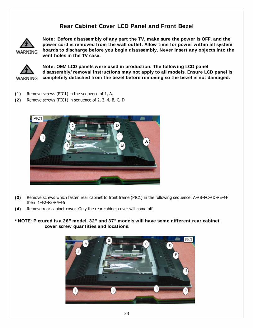
Rear Cabinet Cover LCD Panel and Front Bezel
Note: Before disassembly of any part the TV, make sure the power is OFF, and the power cord is removed from the wall outlet. Allow time for power within all system boards to discharge before you begin disassembly. Never insert any objects into the vent holes in the TV case. Note: OEM LCD panels were used in production. The following LCD panel disassembly/removal instructions may not apply to all models. Ensure LCD panel is completely detached from the bezel before removing so the bezel is not damaged.
(1) Remove screws (PIC1) in the sequence of 1, A. (2) Remove screws (PIC1) in sequence of 2, 3, 4, B, C, D
(3) Remove screws which fasten rear cabinet to front frame (PIC1) in the following sequence: A B C D E F
then 1 2 3 4 5 (4) Remove rear cabinet cover. Only the rear cabinet cover will come off.
*NOTE: Pictured is a 26” model. 32” and 37” models will have some different rear cabinet
cover screw quantities and locations.
23
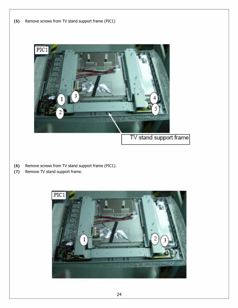
(5) Remove screws from TV stand support frame (PIC1)
(6) Remove screws from TV stand support frame (PIC1). (7) Remove TV stand support frame.
24
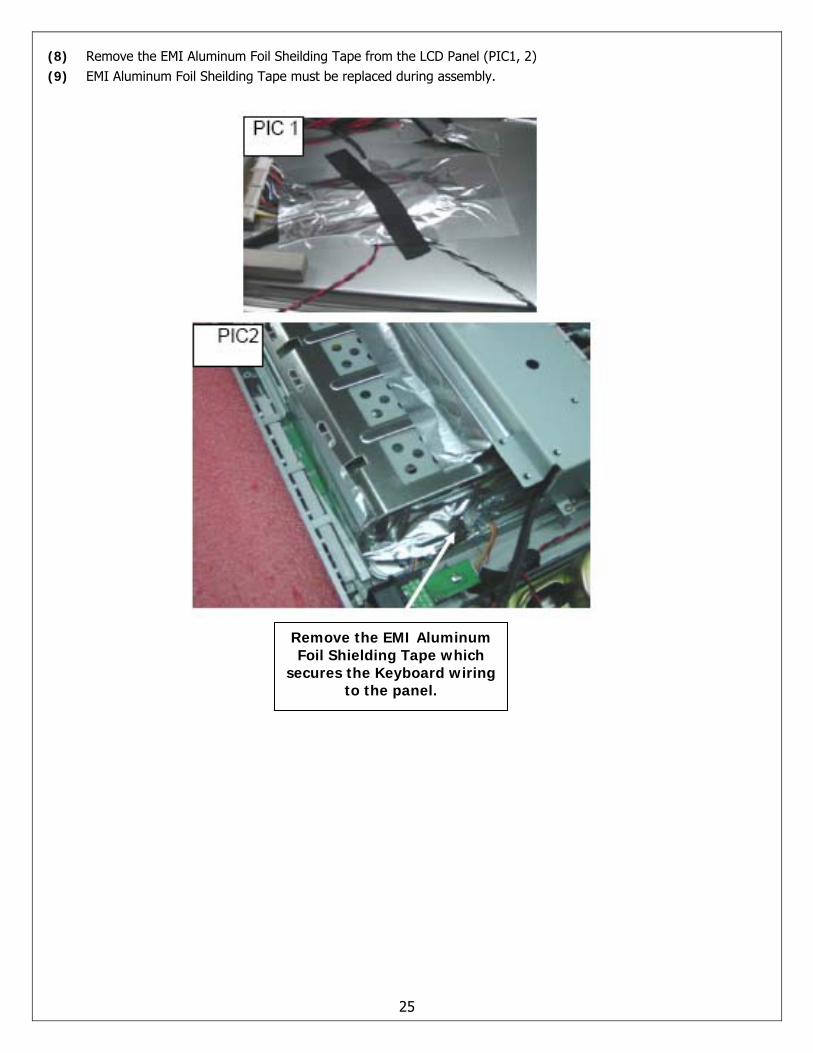
(8) Remove the EMI Aluminum Foil Sheilding Tape from the LCD Panel (PIC1, 2) (9) EMI Aluminum Foil Sheilding Tape must be replaced during assembly.
Remove the EMI Aluminum Foil Shielding Tape which
secures the Keyboard wiring to the panel.
25
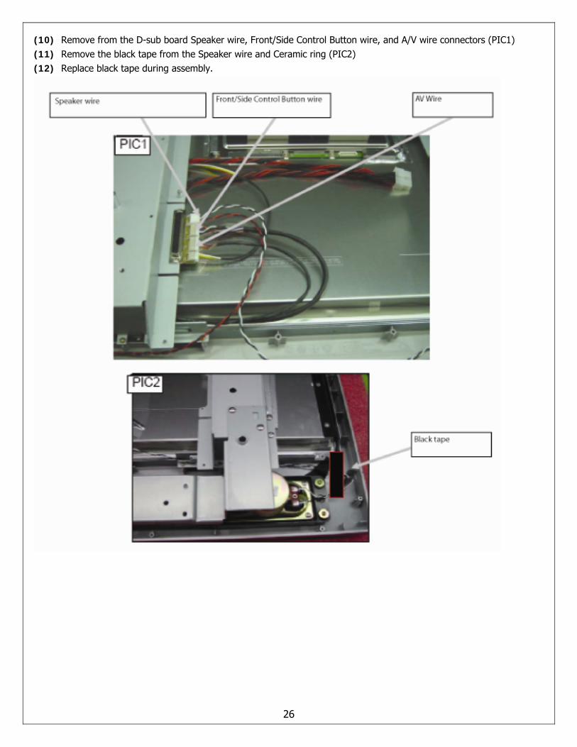
(10) Remove from the D-sub board Speaker wire, Front/Side Control Button wire, and A/V wire connectors (PIC1) (11) Remove the black tape from the Speaker wire and Ceramic ring (PIC2) (12) Replace black tape during assembly.
26
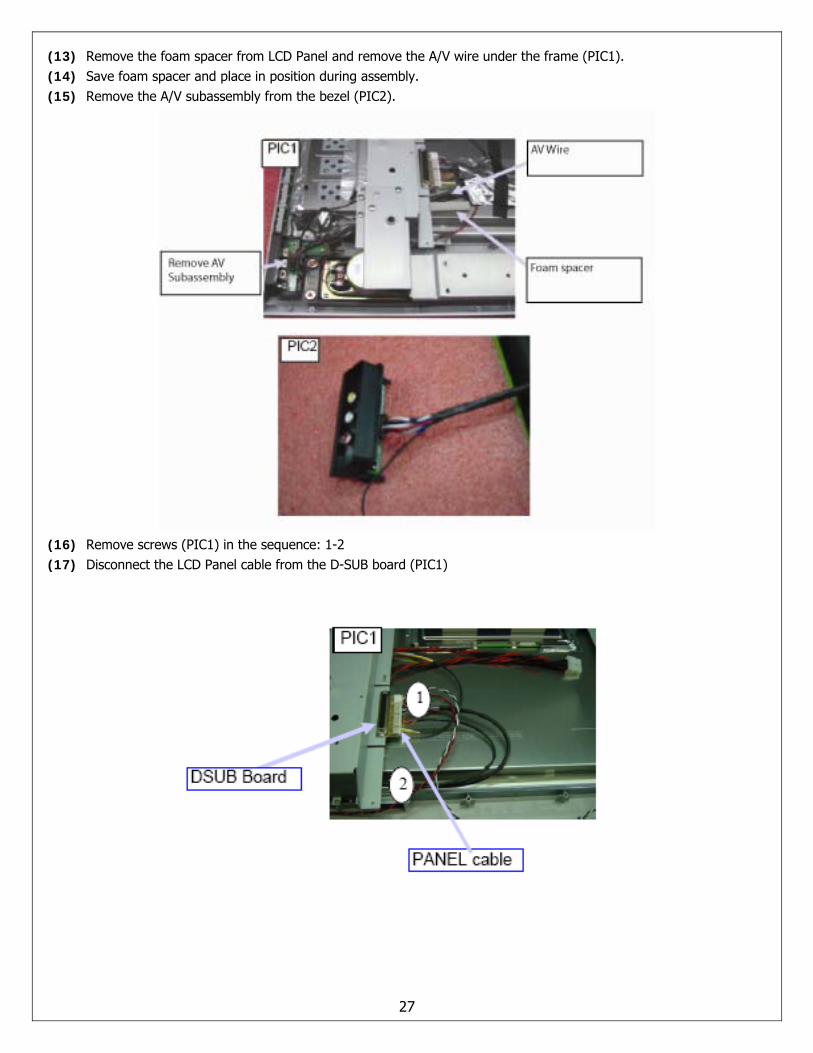
(13) Remove the foam spacer from LCD Panel and remove the A/V wire under the frame (PIC1). (14) Save foam spacer and place in position during assembly. (15) Remove the A/V subassembly from the bezel (PIC2).
(16) Remove screws (PIC1) in the sequence: 1-2 (17) Disconnect the LCD Panel cable from the D-SUB board (PIC1)
27
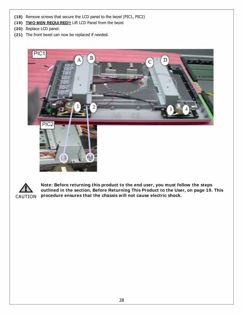
(18) Remove screws that secure the LCD panel to the bezel (PIC1, PIC2) (19) TWO MEN REQUIRED!! Lift LCD Panel from the bezel (20) Replace LCD panel. (21) The front bezel can now be replaced if needed.
Note: Before returning this product to the end user, you must follow the steps outlined in the section, Before Returning This Product to the User, on page 19. This procedure ensures that the chassis will not cause electric shock.
28
A/V Board Removal and Replacement Note: Before disassembly of any part the TV, make sure the power is OFF, and the power cord is removed from the wall outlet. Allow time for power within all system boards to discharge before you begin disassembly. Never insert any objects into the vent holes in the TV case.
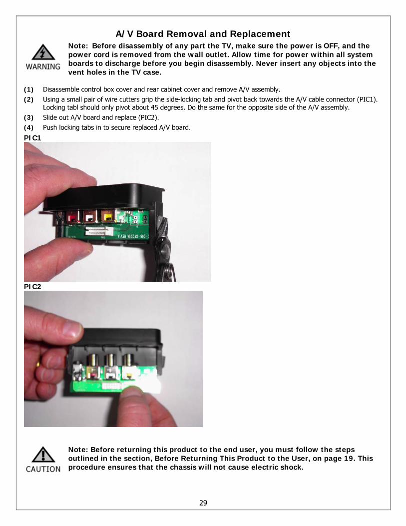
(1) Disassemble control box cover and rear cabinet cover and remove A/V assembly. (2) Using a small pair of wire cutters grip the side-locking tab and pivot back towards the A/V cable connector (PIC1).
Locking tabl should only pivot about 45 degrees. Do the same for the opposite side of the A/V assembly. (3) Slide out A/V board and replace (PIC2). (4) Push locking tabs in to secure replaced A/V board.
PIC1
PIC2
Note: Before returning this product to the end user, you must follow the steps outlined in the section, Before Returning This Product to the User, on page 19. This procedure ensures that the chassis will not cause electric shock.
29
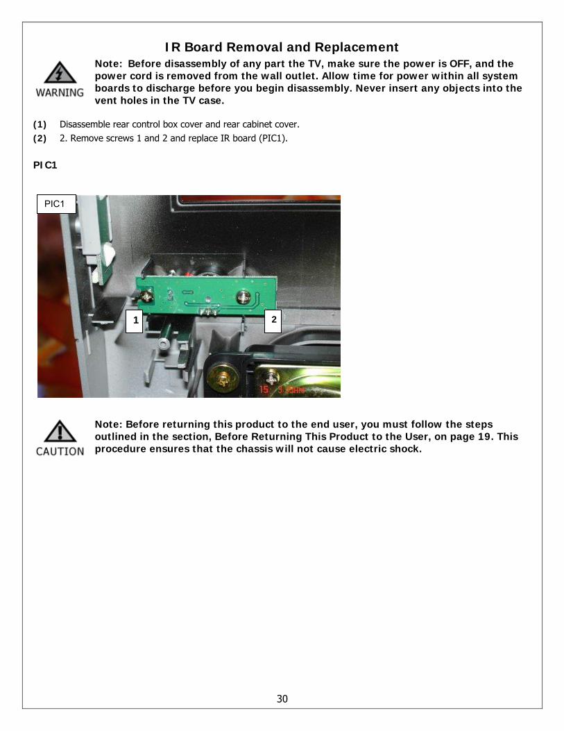
IR Board Removal and Replacement Note: Before disassembly of any part the TV, make sure the power is OFF, and the power cord is removed from the wall outlet. Allow time for power within all system boards to discharge before you begin disassembly. Never insert any objects into the vent holes in the TV case.
(1) Disassemble rear control box cover and rear cabinet cover. (2) 2. Remove screws 1 and 2 and replace IR board (PIC1).
PIC1
30
Note: Before returning this product to the end user, you must follow the steps outlined in the section, Before Returning This Product to the User, on page 19. This procedure ensures that the chassis will not cause electric shock.
1 2
PIC1
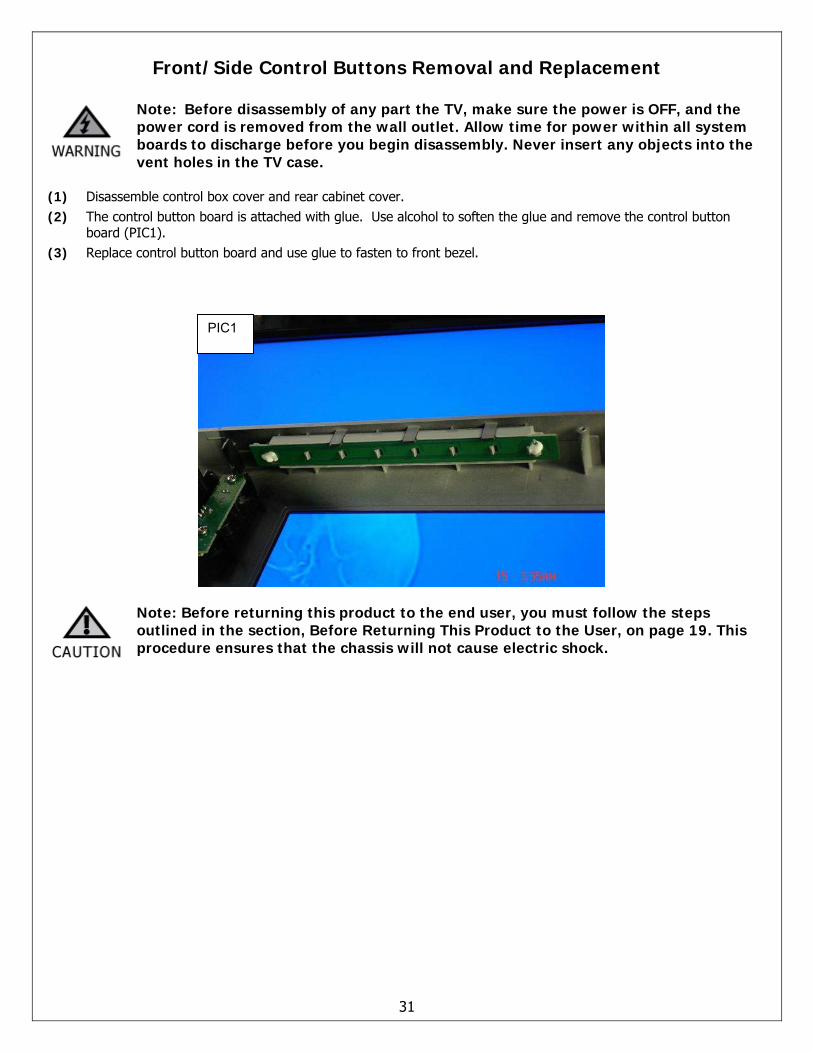
Front/Side Control Buttons Removal and Replacement
Note: Before disassembly of any part the TV, make sure the power is OFF, and the power cord is removed from the wall outlet. Allow time for power within all system boards to discharge before you begin disassembly. Never insert any objects into the vent holes in the TV case.
(1) Disassemble control box cover and rear cabinet cover. (2) The control button board is attached with glue. Use alcohol to soften the glue and remove the control button
board (PIC1). (3) Replace control button board and use glue to fasten to front bezel.
Note: Before returning this product to the end user, you must follow the steps outlined in the section, Before Returning This Product to the User, on page 19. This procedure ensures that the chassis will not cause electric shock.
31
PIC1
6. Spare Parts Lists – FLM-Series 26, 32, 37
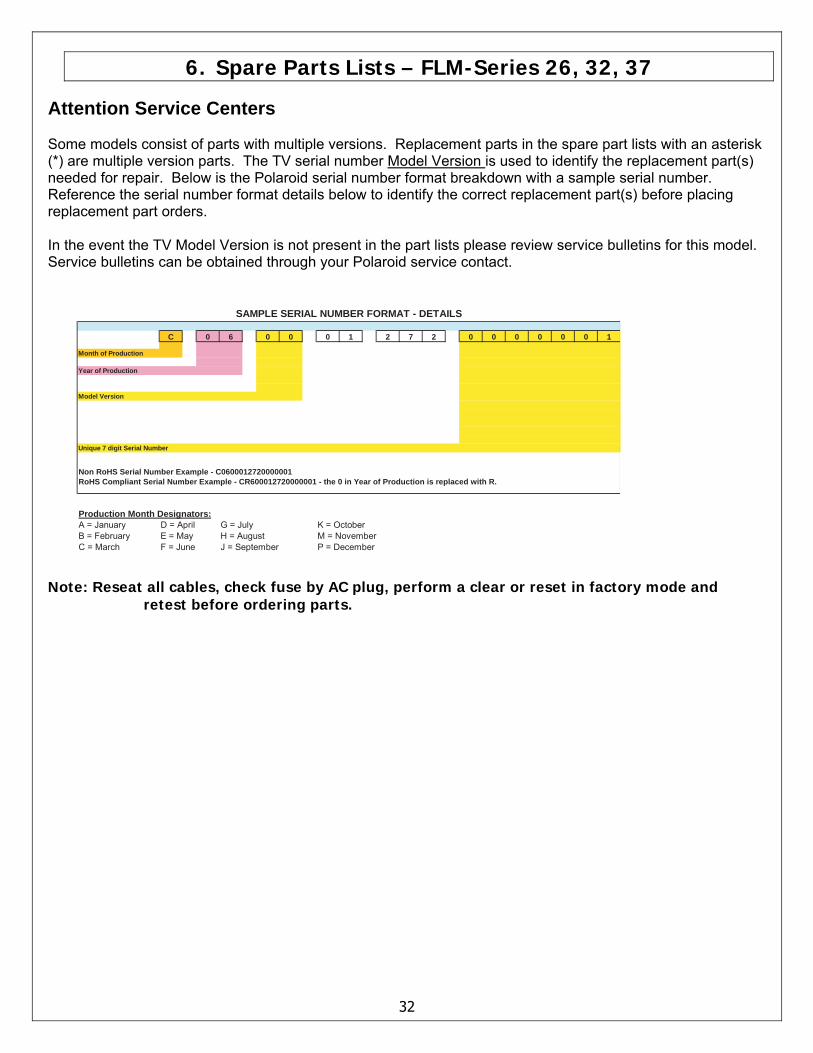
Attention Service Centers Some models consist of parts with multiple versions. Replacement parts in the spare part lists with an asterisk (*) are multiple version parts. The TV serial number Model Version is used to identify the replacement part(s) needed for repair. Below is the Polaroid serial number format breakdown with a sample serial number. Reference the serial number format details below to identify the correct replacement part(s) before placing replacement part orders. In the event the TV Model Version is not present in the part lists please review service bulletins for this model. Service bulletins can be obtained through your Polaroid service contact.
C 0 6 0 0 0 1 2 7 2 0 0 0 0 0 0 1
Month of Production
Year of Production
Model Version
Unique 7 digit Serial Number
Non RoHS Serial Number Example - C0600012720000001RoHS Compliant Serial Number Example - CR600012720000001 - the 0 in Year of Production is replaced with R.
Production Month Designators:A = January D = April G = July K = OctoberB = February E = May H = August M = NovemberC = March F = June J = September P = December
SAMPLE SERIAL NUMBER FORMAT - DETAILS
32
Note: Reseat all cables, check fuse by AC plug, perform a clear or reset in factory mode and retest before ordering parts.
33
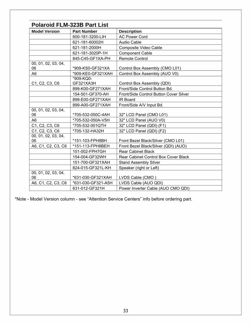
Polaroid FLM-323B Part List Model Version Part Number Description 600-181-3200-LIH AC Power Cord 621-181-60002H Audio Cable 621-181-2000H Composite Video Cable 621-181-3020P-1H Component Cable 845-C45-GF1XA-PH Remote Control 00, 01, 02, 03, 04, 06 *909-KS0-GF321XA Control Box Assembly (CMO L01) A6 *909-KE0-GF321XAH Control Box Assembly (AUO V0)
C1, C2, C3, C6 *909-KQ0-GF321XA3H Control Box Assembly (QDI)
899-K00-GF271XAH Front/Side Control Button Bd. 154-501-GF370-AH Front/Side Control Button Cover Silver 899-E00-GF271XAH IR Board 899-A00-GF271XAH Front/Side A/V Input Bd. 00, 01, 02, 03, 04, 06 *705-532-050C-4AH 32" LCD Panel (CMO L01) A6 *705-532-050A-V5H 32" LCD Panel (AUO V0) C1, C2, C3, C6 *705-532-001QTH 32" LCD Panel (QDI) (F1) C1, C2, C3, C6 *705-132-HA32H 32" LCD Panel (QDI) (F2) 00, 01, 02, 03, 04, 06 *151-103-FPH8BH Front Bezel Black/Silver (CMO L01) A6, C1, C2, C3, C6 *151-113-FPH8BEH Front Bezel Black/Silver (QDI) (AUO) 151-002-FPH7GH Rear Cabinet Black 154-004-GF32WH Rear Cabinet Control Box Cover Black 151-700-GF321XAH Stand Assembly Silver 824-015-GF321L-KH Speaker (right or Left) 00, 01, 02, 03, 04, 06 *631-030-GF321XAH LVDS Cable (CMO ) A6, C1, C2, C3, C6 *631-030-GF321-A5H LVDS Cable (AUO QDI) 631-012-GF321H Power Inverter Cable (AUO CMO QDI)
*Note - Model Version column - see “Attention Service Centers” info before ordering part.
34
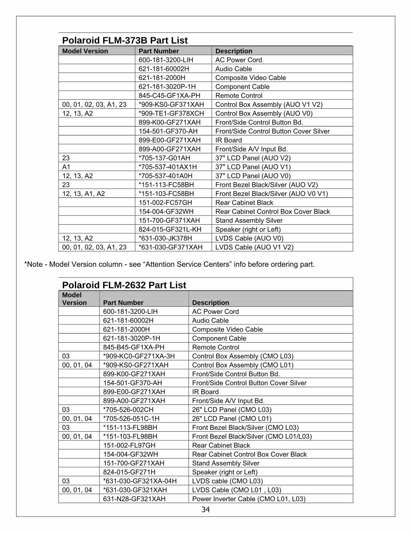
Polaroid FLM-373B Part List Model Version Part Number Description 600-181-3200-LIH AC Power Cord 621-181-60002H Audio Cable 621-181-2000H Composite Video Cable 621-181-3020P-1H Component Cable 845-C45-GF1XA-PH Remote Control 00, 01, 02, 03, A1, 23 *909-KS0-GF371XAH Control Box Assembly (AUO V1 V2) 12, 13, A2 *909-TE1-GF378XCH Control Box Assembly (AUO V0) 899-K00-GF271XAH Front/Side Control Button Bd. 154-501-GF370-AH Front/Side Control Button Cover Silver 899-E00-GF271XAH IR Board 899-A00-GF271XAH Front/Side A/V Input Bd. 23 *705-137-G01AH 37" LCD Panel (AUO V2) A1 *705-537-401AX1H 37" LCD Panel (AUO V1) 12, 13, A2 *705-537-401A0H 37" LCD Panel (AUO V0) 23 *151-113-FC58BH Front Bezel Black/Silver (AUO V2) 12, 13, A1, A2 *151-103-FC58BH Front Bezel Black/Silver (AUO V0 V1) 151-002-FC57GH Rear Cabinet Black 154-004-GF32WH Rear Cabinet Control Box Cover Black 151-700-GF371XAH Stand Assembly Silver 824-015-GF321L-KH Speaker (right or Left) 12, 13, A2 *631-030-JK378H LVDS Cable (AUO V0) 00, 01, 02, 03, A1, 23 *631-030-GF371XAH LVDS Cable (AUO V1 V2)
*Note - Model Version column - see “Attention Service Centers” info before ordering part.
Polaroid FLM-2632 Part List Model Version Part Number Description 600-181-3200-LIH AC Power Cord 621-181-60002H Audio Cable 621-181-2000H Composite Video Cable 621-181-3020P-1H Component Cable 845-B45-GF1XA-PH Remote Control 03 *909-KC0-GF271XA-3H Control Box Assembly (CMO L03) 00, 01, 04 *909-KS0-GF271XAH Control Box Assembly (CMO L01) 899-K00-GF271XAH Front/Side Control Button Bd. 154-501-GF370-AH Front/Side Control Button Cover Silver 899-E00-GF271XAH IR Board 899-A00-GF271XAH Front/Side A/V Input Bd. 03 *705-526-002CH 26" LCD Panel (CMO L03) 00, 01, 04 *705-526-051C-1H 26" LCD Panel (CMO L01) 03 *151-113-FL98BH Front Bezel Black/Silver (CMO L03) 00, 01, 04 *151-103-FL98BH Front Bezel Black/Silver (CMO L01/L03) 151-002-FL97GH Rear Cabinet Black 154-004-GF32WH Rear Cabinet Control Box Cover Black 151-700-GF271XAH Stand Assembly Silver 824-015-GF271H Speaker (right or Left) 03 *631-030-GF321XA-04H LVDS cable (CMO L03) 00, 01, 04 *631-030-GF321XAH LVDS Cable (CMO L01 , L03) 631-N28-GF321XAH Power Inverter Cable (CMO L01, L03)
35
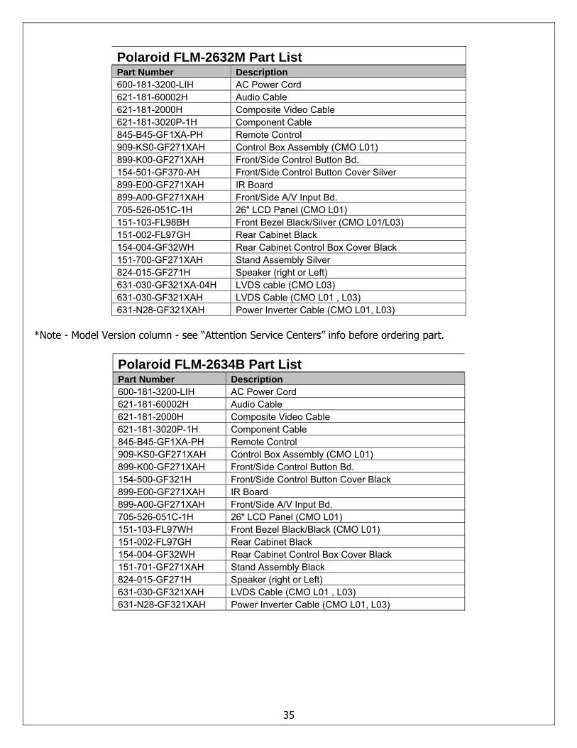
Polaroid FLM-2632M Part List Part Number Description 600-181-3200-LIH AC Power Cord 621-181-60002H Audio Cable 621-181-2000H Composite Video Cable 621-181-3020P-1H Component Cable 845-B45-GF1XA-PH Remote Control 909-KS0-GF271XAH Control Box Assembly (CMO L01) 899-K00-GF271XAH Front/Side Control Button Bd. 154-501-GF370-AH Front/Side Control Button Cover Silver 899-E00-GF271XAH IR Board 899-A00-GF271XAH Front/Side A/V Input Bd. 705-526-051C-1H 26" LCD Panel (CMO L01) 151-103-FL98BH Front Bezel Black/Silver (CMO L01/L03) 151-002-FL97GH Rear Cabinet Black 154-004-GF32WH Rear Cabinet Control Box Cover Black 151-700-GF271XAH Stand Assembly Silver 824-015-GF271H Speaker (right or Left) 631-030-GF321XA-04H LVDS cable (CMO L03) 631-030-GF321XAH LVDS Cable (CMO L01 , L03) 631-N28-GF321XAH Power Inverter Cable (CMO L01, L03)
*Note - Model Version column - see “Attention Service Centers” info before ordering part.
Polaroid FLM-2634B Part List Part Number Description 600-181-3200-LIH AC Power Cord 621-181-60002H Audio Cable 621-181-2000H Composite Video Cable 621-181-3020P-1H Component Cable 845-B45-GF1XA-PH Remote Control 909-KS0-GF271XAH Control Box Assembly (CMO L01) 899-K00-GF271XAH Front/Side Control Button Bd. 154-500-GF321H Front/Side Control Button Cover Black 899-E00-GF271XAH IR Board 899-A00-GF271XAH Front/Side A/V Input Bd. 705-526-051C-1H 26" LCD Panel (CMO L01) 151-103-FL97WH Front Bezel Black/Black (CMO L01) 151-002-FL97GH Rear Cabinet Black 154-004-GF32WH Rear Cabinet Control Box Cover Black 151-701-GF271XAH Stand Assembly Black 824-015-GF271H Speaker (right or Left) 631-030-GF321XAH LVDS Cable (CMO L01 , L03) 631-N28-GF321XAH Power Inverter Cable (CMO L01, L03)
36
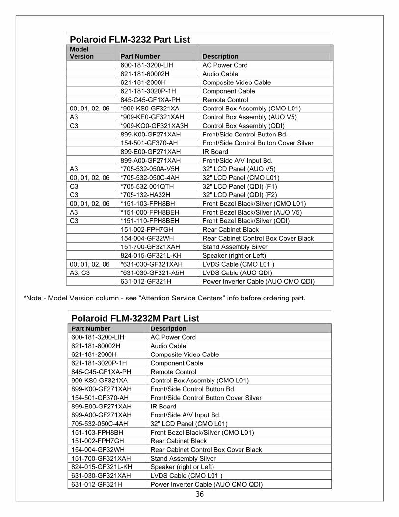
Polaroid FLM-3232 Part List Model Version Part Number Description 600-181-3200-LIH AC Power Cord 621-181-60002H Audio Cable 621-181-2000H Composite Video Cable 621-181-3020P-1H Component Cable 845-C45-GF1XA-PH Remote Control 00, 01, 02, 06 *909-KS0-GF321XA Control Box Assembly (CMO L01) A3 *909-KE0-GF321XAH Control Box Assembly (AUO V5) C3 *909-KQ0-GF321XA3H Control Box Assembly (QDI) 899-K00-GF271XAH Front/Side Control Button Bd. 154-501-GF370-AH Front/Side Control Button Cover Silver 899-E00-GF271XAH IR Board 899-A00-GF271XAH Front/Side A/V Input Bd. A3 *705-532-050A-V5H 32" LCD Panel (AUO V5) 00, 01, 02, 06 *705-532-050C-4AH 32" LCD Panel (CMO L01) C3 *705-532-001QTH 32" LCD Panel (QDI) (F1) C3 *705-132-HA32H 32" LCD Panel (QDI) (F2) 00, 01, 02, 06 *151-103-FPH8BH Front Bezel Black/Silver (CMO L01) A3 *151-000-FPH8BEH Front Bezel Black/Silver (AUO V5) C3 *151-110-FPH8BEH Front Bezel Black/Silver (QDI) 151-002-FPH7GH Rear Cabinet Black 154-004-GF32WH Rear Cabinet Control Box Cover Black 151-700-GF321XAH Stand Assembly Silver 824-015-GF321L-KH Speaker (right or Left) 00, 01, 02, 06 *631-030-GF321XAH LVDS Cable (CMO L01 ) A3, C3 *631-030-GF321-A5H LVDS Cable (AUO QDI) 631-012-GF321H Power Inverter Cable (AUO CMO QDI)
*Note - Model Version column - see “Attention Service Centers” info before ordering part.
Polaroid FLM-3232M Part List Part Number Description 600-181-3200-LIH AC Power Cord 621-181-60002H Audio Cable 621-181-2000H Composite Video Cable 621-181-3020P-1H Component Cable 845-C45-GF1XA-PH Remote Control 909-KS0-GF321XA Control Box Assembly (CMO L01) 899-K00-GF271XAH Front/Side Control Button Bd. 154-501-GF370-AH Front/Side Control Button Cover Silver 899-E00-GF271XAH IR Board 899-A00-GF271XAH Front/Side A/V Input Bd. 705-532-050C-4AH 32" LCD Panel (CMO L01) 151-103-FPH8BH Front Bezel Black/Silver (CMO L01) 151-002-FPH7GH Rear Cabinet Black 154-004-GF32WH Rear Cabinet Control Box Cover Black 151-700-GF321XAH Stand Assembly Silver 824-015-GF321L-KH Speaker (right or Left) 631-030-GF321XAH LVDS Cable (CMO L01 ) 631-012-GF321H Power Inverter Cable (AUO CMO QDI)
37
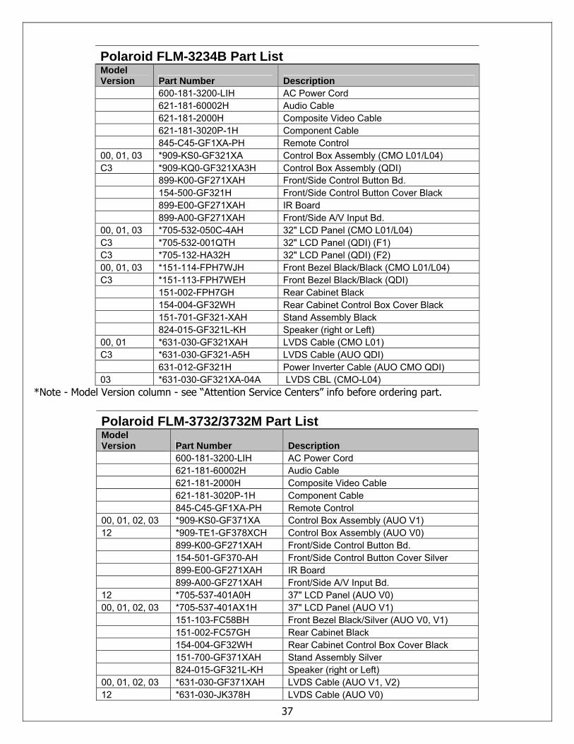
Polaroid FLM-3234B Part List Model Version Part Number Description 600-181-3200-LIH AC Power Cord 621-181-60002H Audio Cable 621-181-2000H Composite Video Cable 621-181-3020P-1H Component Cable 845-C45-GF1XA-PH Remote Control 00, 01, 03 *909-KS0-GF321XA Control Box Assembly (CMO L01/L04) C3 *909-KQ0-GF321XA3H Control Box Assembly (QDI) 899-K00-GF271XAH Front/Side Control Button Bd. 154-500-GF321H Front/Side Control Button Cover Black 899-E00-GF271XAH IR Board 899-A00-GF271XAH Front/Side A/V Input Bd. 00, 01, 03 *705-532-050C-4AH 32" LCD Panel (CMO L01/L04) C3 *705-532-001QTH 32" LCD Panel (QDI) (F1) C3 *705-132-HA32H 32" LCD Panel (QDI) (F2) 00, 01, 03 *151-114-FPH7WJH Front Bezel Black/Black (CMO L01/L04) C3 *151-113-FPH7WEH Front Bezel Black/Black (QDI) 151-002-FPH7GH Rear Cabinet Black 154-004-GF32WH Rear Cabinet Control Box Cover Black 151-701-GF321-XAH Stand Assembly Black 824-015-GF321L-KH Speaker (right or Left) 00, 01 *631-030-GF321XAH LVDS Cable (CMO L01) C3 *631-030-GF321-A5H LVDS Cable (AUO QDI) 631-012-GF321H Power Inverter Cable (AUO CMO QDI) 03 *631-030-GF321XA-04A LVDS CBL (CMO-L04)
*Note - Model Version column - see “Attention Service Centers” info before ordering part.
Polaroid FLM-3732/3732M Part List Model Version Part Number Description 600-181-3200-LIH AC Power Cord 621-181-60002H Audio Cable 621-181-2000H Composite Video Cable 621-181-3020P-1H Component Cable 845-C45-GF1XA-PH Remote Control 00, 01, 02, 03 *909-KS0-GF371XA Control Box Assembly (AUO V1) 12 *909-TE1-GF378XCH Control Box Assembly (AUO V0) 899-K00-GF271XAH Front/Side Control Button Bd. 154-501-GF370-AH Front/Side Control Button Cover Silver 899-E00-GF271XAH IR Board 899-A00-GF271XAH Front/Side A/V Input Bd. 12 *705-537-401A0H 37" LCD Panel (AUO V0) 00, 01, 02, 03 *705-537-401AX1H 37" LCD Panel (AUO V1) 151-103-FC58BH Front Bezel Black/Silver (AUO V0, V1) 151-002-FC57GH Rear Cabinet Black 154-004-GF32WH Rear Cabinet Control Box Cover Black 151-700-GF371XAH Stand Assembly Silver 824-015-GF321L-KH Speaker (right or Left) 00, 01, 02, 03 *631-030-GF371XAH LVDS Cable (AUO V1, V2) 12 *631-030-JK378H LVDS Cable (AUO V0)
38
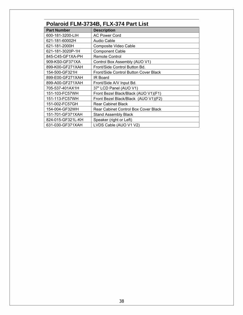
Polaroid FLM-3734B, FLX-374 Part List Part Number Description 600-181-3200-LIH AC Power Cord 621-181-60002H Audio Cable 621-181-2000H Composite Video Cable 621-181-3020P-1H Component Cable 845-C45-GF1XA-PH Remote Control 909-KS0-GF371XA Control Box Assembly (AUO V1) 899-K00-GF271XAH Front/Side Control Button Bd. 154-500-GF321H Front/Side Control Button Cover Black 899-E00-GF271XAH IR Board 899-A00-GF271XAH Front/Side A/V Input Bd. 705-537-401AX1H 37" LCD Panel (AUO V1) 151-103-FC57WH Front Bezel Black/Black (AUO V1)(F1) 151-113-FC57WH Front Bezel Black/Black (AUO V1)(F2) 151-002-FC57GH Rear Cabinet Black 154-004-GF32WH Rear Cabinet Control Box Cover Black 151-701-GF371XAH Stand Assembly Black 824-015-GF321L-KH Speaker (right or Left) 631-030-GF371XAH LVDS Cable (AUO V1 V2)
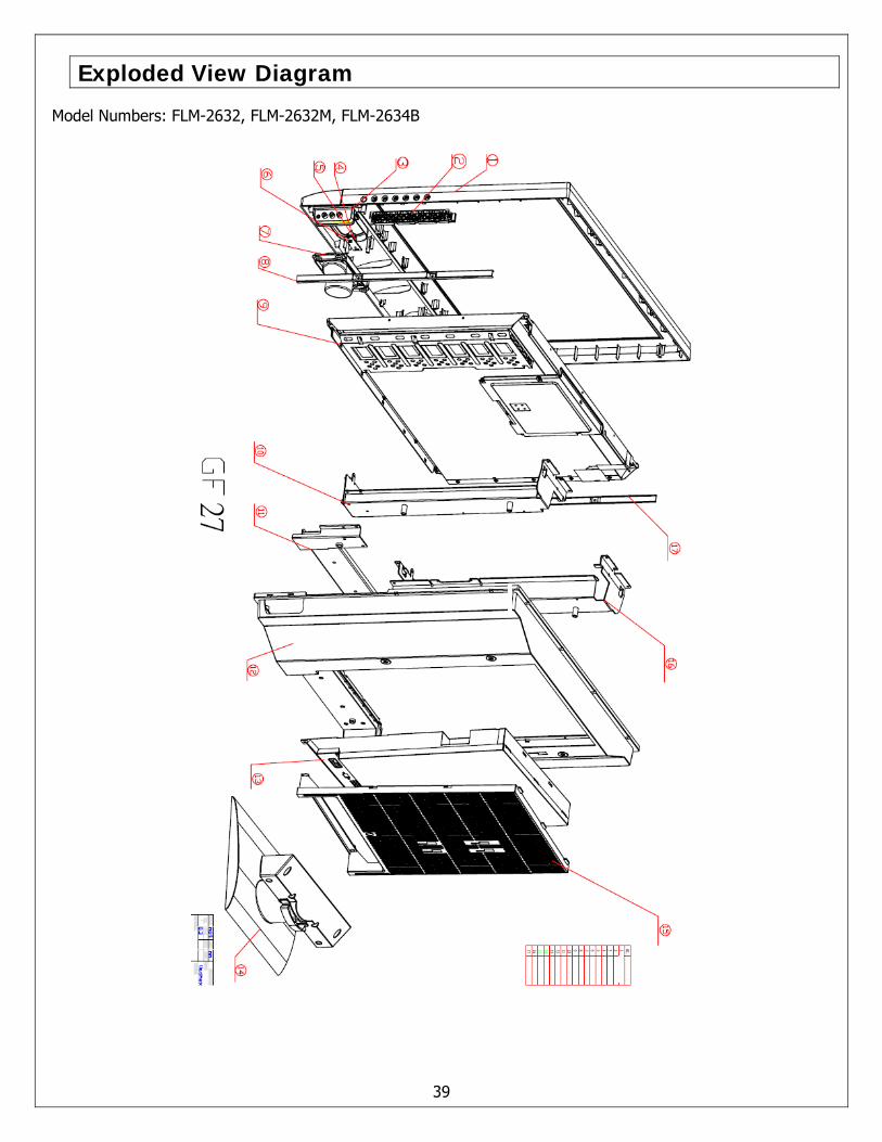
Exploded View Diagram
Model Numbers: FLM-2632, FLM-2632M, FLM-2634B
39
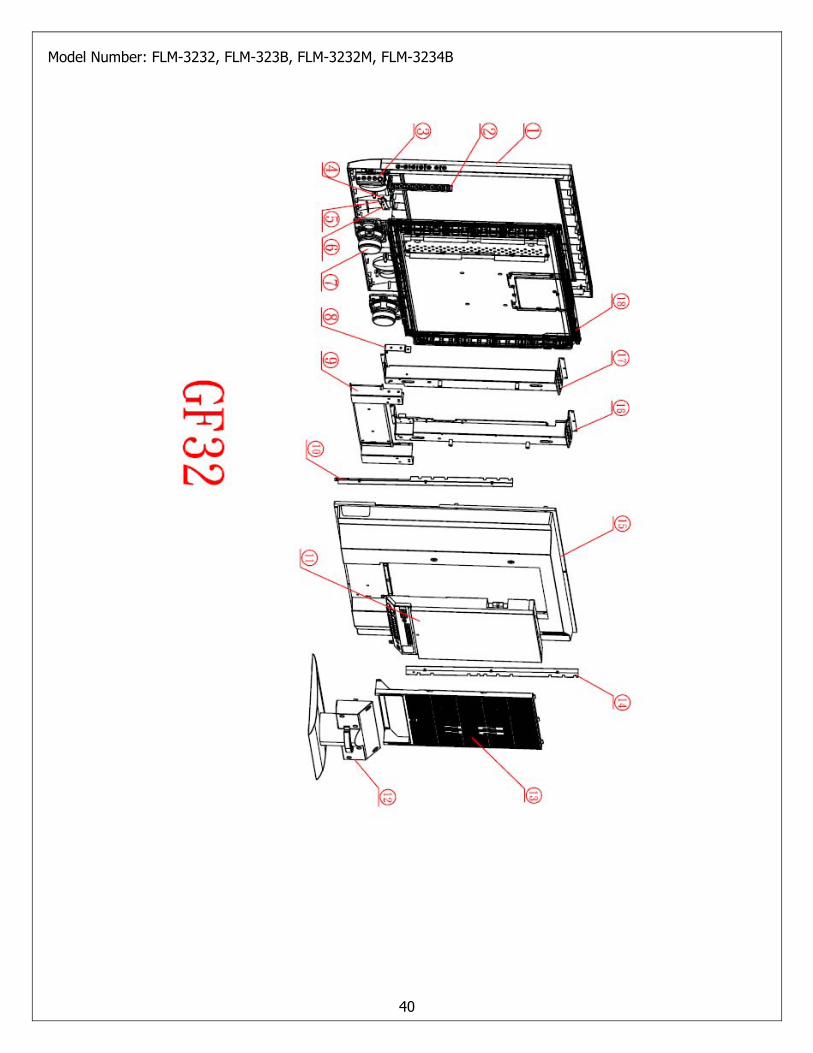
Model Number: FLM-3232, FLM-323B, FLM-3232M, FLM-3234B
40
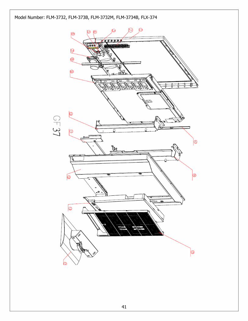
Model Number: FLM-3732, FLM-373B, FLM-3732M, FLM-3734B, FLX-374
41
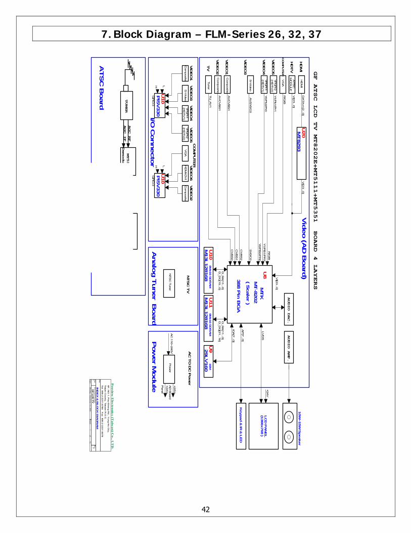
7. Block Diagram – FLM-Series 26, 32, 37
42
PI
U105V330
H L
GP
IO-3
CV
BS
1
ATS
C B
oard
Analo
g T
uner B
oard
I/O C
onnecto
rP
ow
er M
odule
Y1/P
B1/P
R1
U11
D_R
A[1
1...0
]D
_D
Q[3
1...1
6]
R/G
/B
YP
bP
r2Y1/P
b1/P
r1VID
EO
5(H
DTV
2)
VID
EO
2C
OM
PU
TERV
IDEO
6
Title
Size
Do
cu
me
nt N
um
be
rR
ev
Date
:S
he
et
of
GF L
CD
TV
B
IND
EX
& B
LO
CK
DIA
GR
AM
Pro
vie
w E
lectro
nic
s (Ta
iwa
n) C
o., L
TD
.6F
, NO
.1, P
au-S
heng R
d., Y
ung-H
o C
ity,
Taip
ei C
ounty
, Taiw
an R
.O.C
.Tel: 8
86-2
-2231-6
789 F
ax: 8
86-2
-2231-5
678
C
112
Mo
nd
ay
, De
ce
mb
er 1
9, 2
00
5
+24V
LV
DS
AUDIO DAC.
AUDIO AMP.
10W
~15W
Speaker
FLASH RAM
MT5351
MT5111
TUNER
DDR RAM
DTV Backend
Decoder SOC
Demodulator
TS OUTPUT
AGC_IF
AGC_RF
VI[2
3...0
]
HD
TV
CO
MP
UTE
R
HD
MI
AC
TO
DC
Pow
er
Pow
er
+24V
Pane
l
AD
Board
+24V
AC
110~240V
M13L128168 3
88 P
in B
GA
8M
x16 S
DR
AM
8M
x16 S
DR
AM
M13L128168
IOA
[7...0
]
VID
EO
2
HD
MI
ATS
C
VG
AR
/G/B
MO
DU
LE
16M
29LV160
U9
Keypad &
IR &
LE
D
LC
D P
AN
EL
(1366x768 )
AP
[7...0
]
MU
20T
8293
DA
TA
+/-[2
...0]
VI[2
3...0
]
VI[2
3...0
]
VI[2
3...0
]
Vid
eo (A
D B
oard
)NTSC
TV
NTS
C T
uner
VID
EO
5
(HD
TV
2)
YP
bP
r2
MT-8
202
HD
MI-D
VI
VID
EO
1
U10
U8
VG
A
Tune
r
( Scale
r )
MTK
VID
EO
3YP
bP
r1S
-Vid
eo
Com
posite
VID
EO
3
TV
YP
bP
r1
S-V
ideo
Com
posite
Com
posite
VID
EO
4
(HD
TV
1)
Com
posite
CV
BS
0
VID
EO
4(H
DTV
1)
AV
CV
BS
1VID
EO
1 GF ATSC LCD TV MT8202E+MT5111+MT5351 BOARD 4 LAYERS
Y0/P
b0/P
r0
D_D
Q[1
5...0
]
AV
SY0/C
0
Y0/P
B0/P
R0
D_R
A[1
1...0
]
CV
BS
2
TU
_A
V1
AV
CV
BS
1
SY0/C
0
PI
U105V330
H L
GP
IO-3
8. Schematics
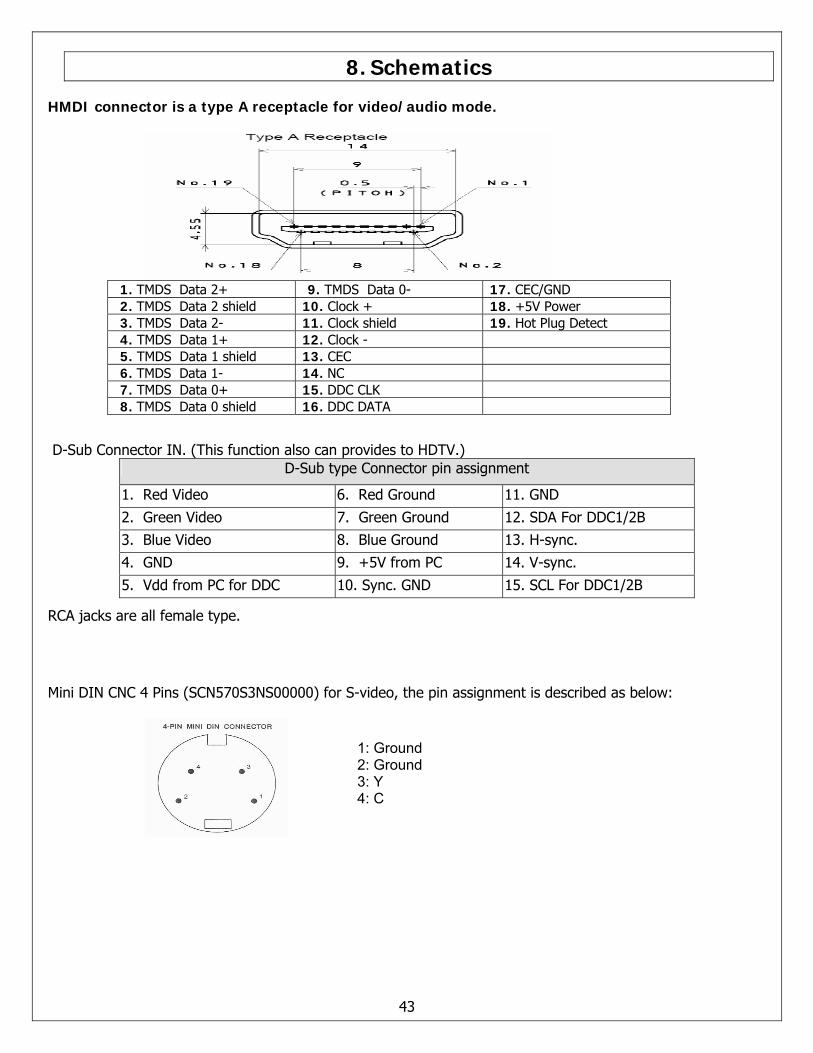
HMDI connector is a type A receptacle for video/audio mode.
1. TMDS Data 2+ 9. TMDS Data 0- 17. CEC/GND 2. TMDS Data 2 shield 10. Clock + 18. +5V Power 3. TMDS Data 2- 11. Clock shield 19. Hot Plug Detect 4. TMDS Data 1+ 12. Clock - 5. TMDS Data 1 shield 13. CEC 6. TMDS Data 1- 14. NC 7. TMDS Data 0+ 15. DDC CLK 8. TMDS Data 0 shield 16. DDC DATA
D-Sub Connector IN. (This function also can provides to HDTV.) D-Sub type Connector pin assignment
1. Red Video 6. Red Ground 11. GND
2. Green Video 7. Green Ground 12. SDA For DDC1/2B 3. Blue Video 8. Blue Ground 13. H-sync. 4. GND 9. +5V from PC 14. V-sync.
5. Vdd from PC for DDC 10. Sync. GND 15. SCL For DDC1/2B
RCA jacks are all female type.
Mini DIN CNC 4 Pins (SCN570S3NS00000) for S-video, the pin assignment is described as below:
43
1: Ground 2: Ground 3: Y 4: C
44
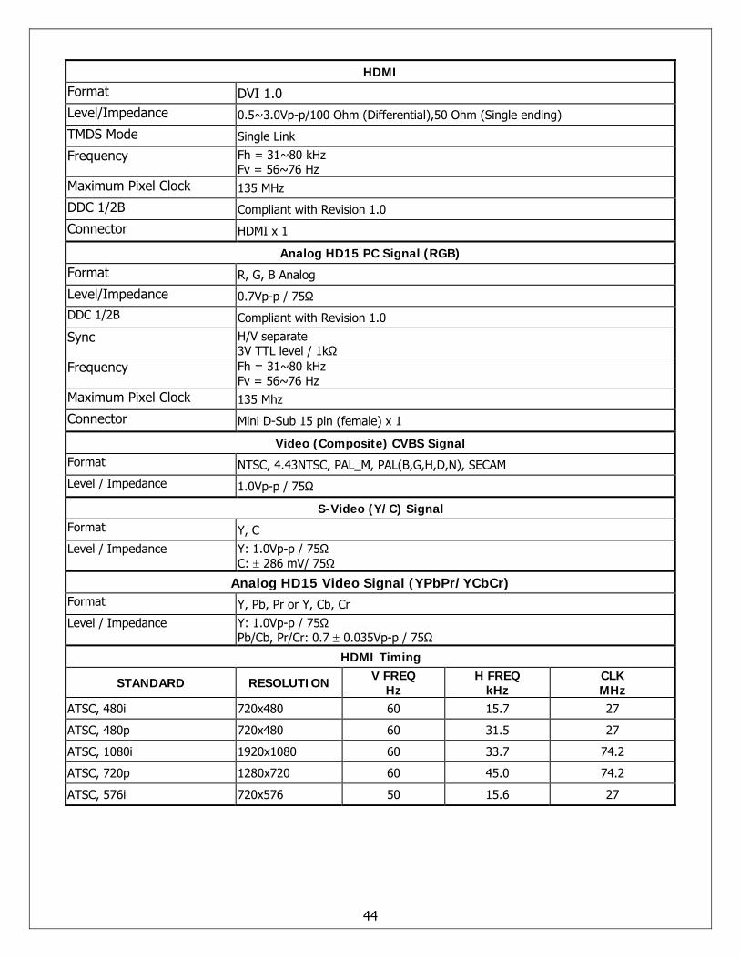
HDMI
Format DVI 1.0 Level/Impedance 0.5~3.0Vp-p/100 Ohm (Differential),50 Ohm (Single ending)
TMDS Mode Single Link
Frequency Fh = 31~80 kHz Fv = 56~76 Hz
Maximum Pixel Clock 135 MHz
DDC 1/2B Compliant with Revision 1.0
Connector HDMI x 1
Analog HD15 PC Signal (RGB)
Format R, G, B Analog
Level/Impedance 0.7Vp-p / 75Ω DDC 1/2B Compliant with Revision 1.0
Sync H/V separate 3V TTL level / 1kΩ
Frequency Fh = 31~80 kHz Fv = 56~76 Hz
Maximum Pixel Clock 135 Mhz
Connector Mini D-Sub 15 pin (female) x 1
Video (Composite) CVBS Signal Format NTSC, 4.43NTSC, PAL_M, PAL(B,G,H,D,N), SECAM Level / Impedance 1.0Vp-p / 75Ω
S-Video (Y/C) Signal Format Y, C Level / Impedance Y: 1.0Vp-p / 75Ω
C: ± 286 mV/ 75Ω
Analog HD15 Video Signal (YPbPr/YCbCr) Format Y, Pb, Pr or Y, Cb, Cr Level / Impedance Y: 1.0Vp-p / 75Ω
Pb/Cb, Pr/Cr: 0.7 ± 0.035Vp-p / 75Ω
HDMI Timing
STANDARD RESOLUTION V FREQ Hz
H FREQ kHz
CLK MHz
ATSC, 480i 720x480 60 15.7 27
ATSC, 480p 720x480 60 31.5 27
ATSC, 1080i 1920x1080 60 33.7 74.2
ATSC, 720p 1280x720 60 45.0 74.2
ATSC, 576i 720x576 50 15.6 27
45
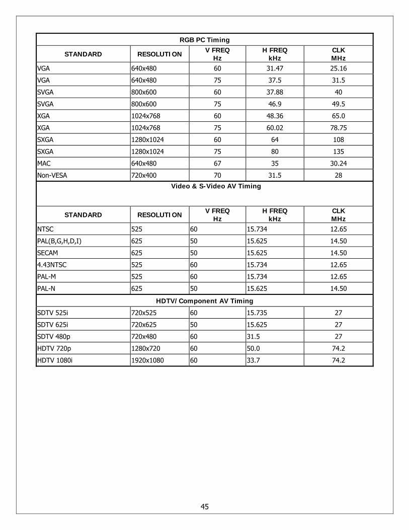
RGB PC Timing
STANDARD RESOLUTION V FREQ Hz
H FREQ kHz
CLK MHz
VGA 640x480 60 31.47 25.16
VGA 640x480 75 37.5 31.5
SVGA 800x600 60 37.88 40
SVGA 800x600 75 46.9 49.5
XGA 1024x768 60 48.36 65.0
XGA 1024x768 75 60.02 78.75
SXGA 1280x1024 60 64 108
SXGA 1280x1024 75 80 135
MAC 640x480 67 35 30.24
Non-VESA 720x400 70 31.5 28
Video & S-Video AV Timing
STANDARD RESOLUTION V FREQ Hz
H FREQ kHz
CLK MHz
NTSC 525 60 15.734 12.65
PAL(B,G,H,D,I) 625 50 15.625 14.50
SECAM 625 50 15.625 14.50
4.43NTSC 525 60 15.734 12.65
PAL-M 525 60 15.734 12.65
PAL-N 625 50 15.625 14.50
HDTV/Component AV Timing
SDTV 525i 720x525 60 15.735 27
SDTV 625i 720x625 50 15.625 27
SDTV 480p 720x480 60 31.5 27
HDTV 720p 1280x720 60 50.0 74.2
HDTV 1080i 1920x1080 60 33.7 74.2
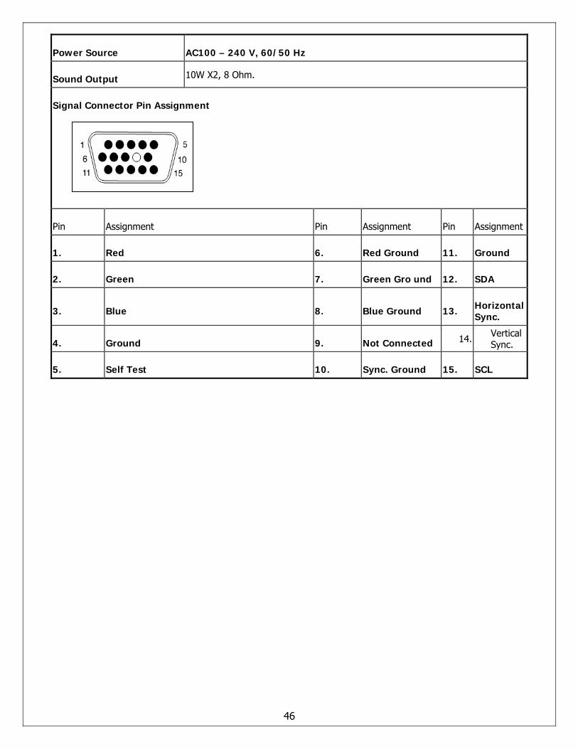
Power Source AC100 – 240 V, 60/50 Hz
Sound Output 10W X2, 8 Ohm.
Signal Connector Pin Assignment
Pin Assignment Pin Assignment Pin Assignment
1. Red 6. Red Ground 11. Ground
2. Green 7. Green Gro und 12. SDA
3. Blue 8. Blue Ground 13. Horizontal Sync.
4. Ground 9. Not Connected 14. Vertical Sync.
5. Self Test 10. Sync. Ground 15. SCL
46
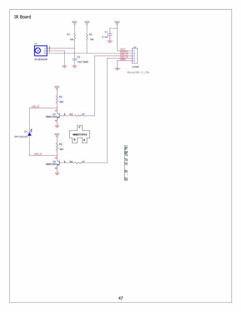
IR Board
47
Title
Size Document Number Rev
Date: Sheet of
GF371-XU A
IR SENSOR PCB
Proview Electronics (Taiwan) Co., LTD.6F, NO.1, Pau-Sheng Rd., Yung-Ho City,Taipei County, Taiwan R.O.C.Tel: 886-2-2231-6789 Fax: 886-2-2232-4613
A
1 1Tuesday , December 20, 2005
Q1MMBT3904
B
EC
R4 47
R6 47
R3
560
LED_O
LED_G
B
MMBT3904
C
E
VCC
U1
IR-SENSOR
O 1G 2V 3
VCC VCC
Q2MMBT3904
B
EC
VCC
VCC
LED_GLED_O
GND
C1
0.1uF
Hous5P-1.0h
R5
560
J1
CON5
12345
D1
DIP LED-D3
VCC
R1
100
R2
10K
IR-OUT
C2
10uF-0805
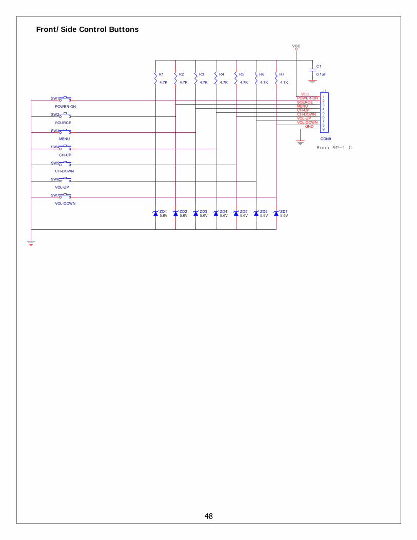
Front/Side Control Buttons
48
ZD25.6V
ZD15.6V
SW2
SOURCE
SW3
MENU
SW4
CH-UP
SW5
CH-DOWN
SW1
POWER-ON
POWER-ONSOERCE
CH-UPMENU
CH-DOWN
Title
Size Document Number Rev
Date: Sheet of
GF371-XU A
KEYPAD PCB
Proview Electronics (Taiwan) Co., LTD.6F, NO.1, Pau-Sheng Rd., Yung-Ho City,Taipei County, Taiwan R.O.C.Tel: 886-2-2231-6789 Fax: 886-2-2232-4613
A
1 1Friday , September 30, 2005
R1
4.7K
R2
4.7K
R3
4.7K
R4
4.7K
R5
4.7K
J1
CON9
123456789
GND
Hous 9P-1.0
VCC
C1
0.1uF
VOL-DOWNVOL-UP
VCC
SW6
VOL-UP
SW7
VOL-DOWN
R6
4.7K
R7
4.7K
ZD75.6V
ZD65.6V
ZD55.6V
ZD35.6V
ZD45.6V
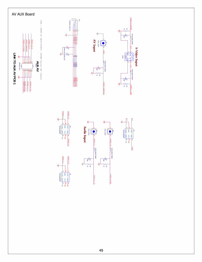
AV AUX Board
49
L3 FB-40-0805-700MA
FR
ON
T_A_R
L5 FB-40-0805-700MA
FR
ON
T_A_L
R3
75
C3
12pF
R5
75
C5
12pF
PHO
NE_A_L
PH
ON
E_A
_DPH
ON
E_A_RU
2RC
lamp0504F
LINE
11
GN
D2
LINE
33
LINE
44
VC
C5
LINE
26
FR
ON
T_A_L
FR
ON
T_A_R
U3RC
lamp0504F
LINE
11
GN
D2
LINE
33
LINE
44
VC
C5
LINE
26
L1F
B-40-0805-700M
AL2
FB
-40-0805-700MA
C1
12pF
S-V
ideo In
pu
t
S_CFR
ON
T_S_LUM
A
R1
75
FR
ON
T_S_C
HR
OM
A
R2
75
C2
12pF
FR
ON
T_CO
MPO
SITE
J3
RC
A JACK
21F
RO
NT_S
_CH
RO
MA
FR
ON
T_S_LU
MA
AV
Inp
ut
FR
ON
T_A_R
_IN
J2
RC
A JACK
21
Au
dio In
pu
t
J4
RC
A JACK
21
FRO
NT_A_L_IN
PHO
NE_A_L_O
PH
ON
E_A
_R_O
PH
ON
E_A
_D_O
R6
0-R0603
R7
0-R0603
R8
0-R0603
C6
C0603_N
C
C7
C0603_N
C
PH
ON
E_A
_DP
HO
NE
_A_R
PJ1PH
ON
E JACK-3.5 124 3
PH
ON
E_A
_L
Title
SizeD
ocument N
umber
Rev
Date:
Sheet
of
GF371-X
UA
AU
X AV PC
B
Proview
Electronics (T
aiwan) C
o., LT
D.
6F, NO
.1, Pau-S
heng Rd., Y
ung-Ho C
ity,Taipei C
ounty, Taiwan R
.O.C
.Tel: 886-2-2231-6789 Fax: 886-2-2232-4613
B
11
Thursday, Novem
ber 24, 2005
GG
CY
J1DIN
4
34
12
S_Y
AUX A
V
CV
BS
CO
N1
200PHD
-14LT
131197531
1412108642
FR
ON
T_A_L_IN
PH
ON
E_A
_D_O
PHO
NE_A_L_O
FR
ON
T_A_R
_IN
CON1 : FRONT AV INPUT/OUTPUT
FR
ON
T_CO
MPO
SITE
PH
ON
E_A
_R_O
LINK TO
AUX A
V PCB
1
200PHD Series 2X8 (16pin)
L4 FB-40-0805-700MA
C4
12pF
R4
75
CVBS
S_C
S_Y
U1RC
lamp0504F
LINE
33
GN
D2
LINE
11
LINE
44
VC
C5
LINE
26
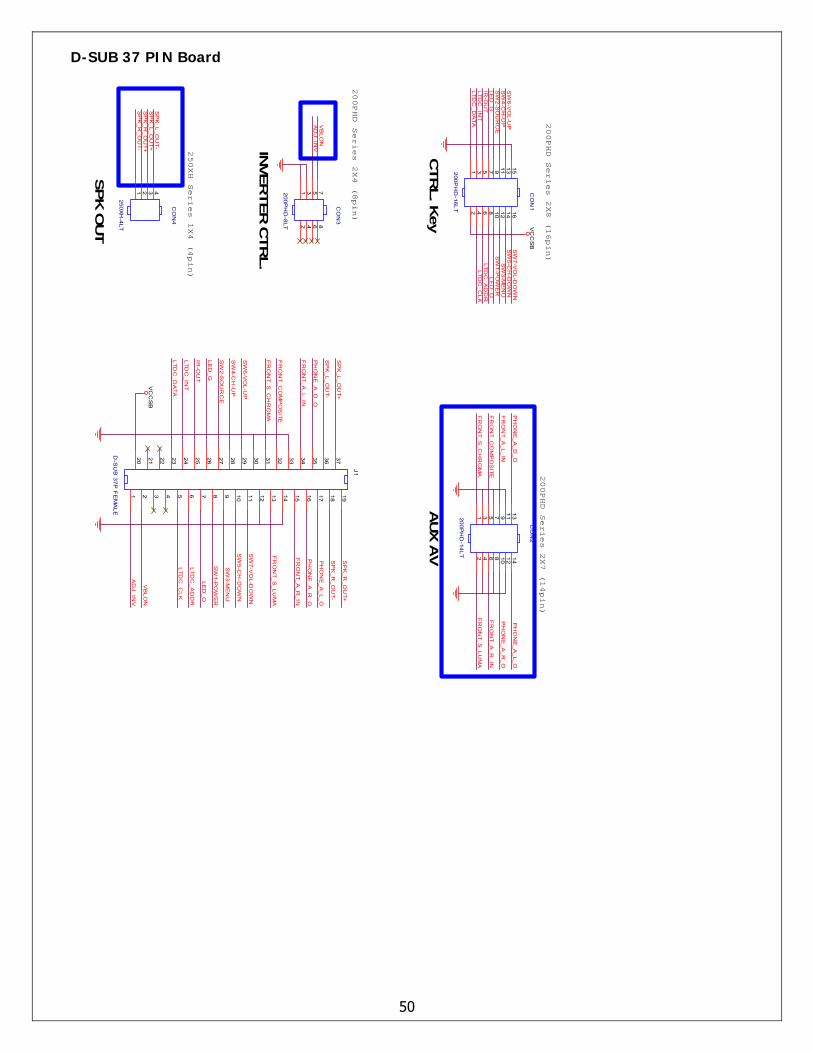
D-SUB 37 PIN Board
50
J1
D-S
UB
37P F
EM
ALE
1918171615141312111098765432120 21 22 23 24 25 26 27 28 29 30 31 32 33 34 35 36 37
CO
N1
200PH
D-16LT
15131197531
161412108642
250XH Series 1X4 (4pin)
200PHD Series 2X4 (8pin)
Title
Size
Docum
ent Num
berR
ev
Date:
Sheet
of
JK379-U
DA
CO
N JU
NC
T D
-SU
B 37P
in
Pro
vie
w E
lectro
nic
s (Ta
iwa
n) C
o., L
TD
.6F
, NO
.1, Pau-S
heng Rd., Y
ung-Ho C
ity,Taipei C
ounty, Taiwan R
.O.C
.Tel: 886-2-2231-6789 F
ax: 886-2-2232-4613
Custom
11
Friday
, Septem
ber 09, 2005
FR
ON
T_S_LU
MA
FR
ON
T_A_L_IN
FR
ON
T_A_R
_IN
VC
CS
B
PH
ON
E_A
_R_O
AD
J_INV
VB
LON
200PHD Series 2X7 (14pin)
AUX
AV
PH
ON
E_A
_L_O
FR
ON
T_S_LU
MA
FR
ON
T_A_R
_IN
PH
ON
E_A
_R_O
FR
ON
T_S_C
HR
OM
A
FR
ON
T_CO
MP
OS
ITE
FR
ON
T_A_L_IN
PH
ON
E_A
_D_O
CO
N2
200PH
D-14LT
131197531
1412108642
LTDC
_DA
TALTD
C_C
LKLTD
C_IN
T
SW
2-SO
UR
CE
IR-O
UT
LTDC
_AD
DR
LED
_GLE
D_O
SW
6-VO
L-UP
SW
5-CH
-DO
WN
SW
3-ME
NU
SW
7-VO
L-DO
WN
SW
4-CH
-UP
SW
1-PO
WE
R
SP
K_R
_OU
T+S
PK
_L_OU
T+
SP
K_R
_OU
T-
SP
K_L_O
UT
-
AD
J_INV
VB
LON
SP
K_R
_OU
T+
SP
K_R
_OU
T-S
PK
_L_OU
T+
SP
K_L_O
UT-
PH
ON
E_A
_L_OP
HO
NE
_A_D
_O
CO
N3
200PH
D-8LT
7531
8642
FR
ON
T_CO
MP
OS
ITE
FR
ON
T_S_C
HR
OM
A
CTR
L. K
ey
INVER
TER
CTR
L.
CO
N4
250XH-4LT
1 2 3 4
SP
K O
UT
200PHD Series 2X8 (16pin)
LTDC
_CLK
SW
3-ME
NU
LED
_OLTD
C_A
DD
R
SW
5-CH
-DO
WN
SW
1-PO
WE
R
SW
7-VO
L-DO
WN
SW
4-CH
-UP
SW
2-SO
UR
CE
LED
_GIR
-OU
T
LTDC
_DA
TALTD
C_IN
T
SW
6-VO
L-UP
VC
CS
B
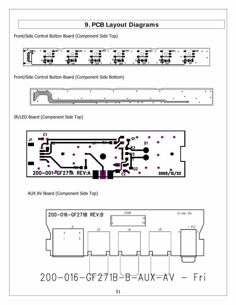
9. PCB Layout Diagrams
Front/Side Control Button Board (Component Side Top)
Front/Side Control Button Board (Component Side Bottom)
IR/LED Board (Component Side Top)
AUX AV Board (Component Side Top)
51
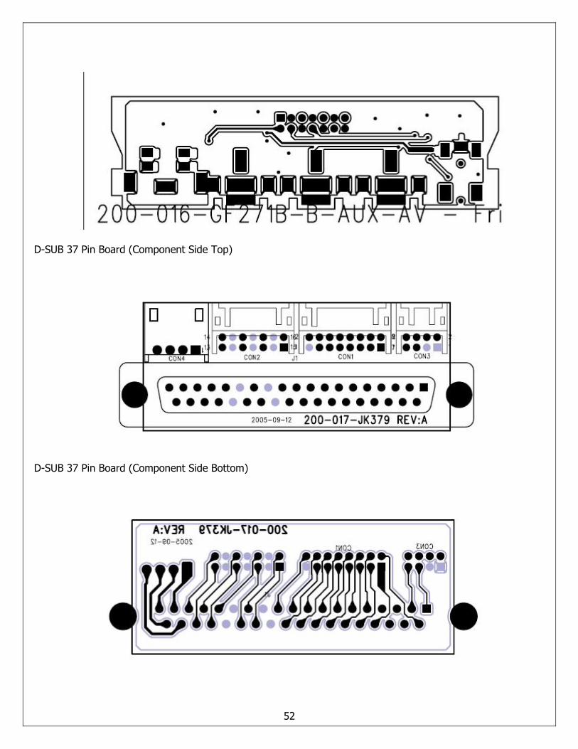
D-SUB 37 Pin Board (Component Side Top)
D-SUB 37 Pin Board (Component Side Bottom)
52