pneumatic valve islands - asco - home asset library/pneumatic valves-valve... · - q 233 pneumatic...
TRANSCRIPT

All leaflets are available on: www.asco.com
Fielbus Electronics - I
Page
➠
501 Series Valve Islands 3..10 30..4445..50
502 Series Valve Islands 11..20/30..44
503 Series Valve Islands 21..29/30..44
2035 Series Valve Islands 51..72
G3 Electronics 73..120
580 Electronics 121..154
501 Series Valve Islands, ATEX 155..166 / 233..238
502 Series Valve Islands, ATEX 167..178 / 179..182G3 Electronics
580 Electronics, ATEX205..228
622 Series Valve Islands, ATEX229..232
ISO 5599/2 Valve Islands 239..256
Spool valves, 502 & 503 Series, with integrated M12 (ISO 15407-1)
259..272273..286
Spool valves, 502 & 503 Series, with integrated M12 on subbase (ISO 15407-2)
287..292293..300
PNEUMATIC VALVE ISLANDS
0183
1GB
-201
7/R
02A
vaila
bilit
y, d
esig
n an
d sp
ecifi
catio
ns a
re s
ubje
ct to
cha
nge
with
out n
otic
e. A
ll rig
hts
rese
rved
.
Valv
e is
land
s
www.asco.com
Pneumatic Valve Islands
Consult the online configurator - CAD files on: www.asco.com
All leaflets are available on: www.asco.com
II - Fielbus Electronics
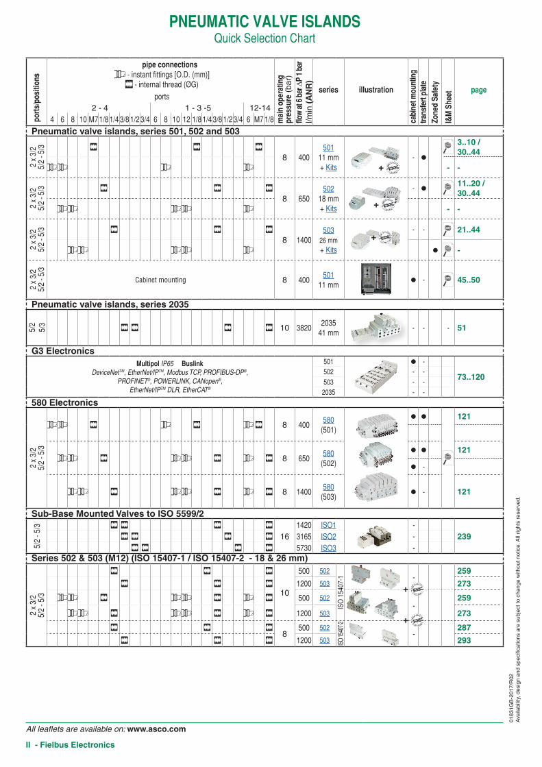
PNEUMATIC VALVE ISLANDSQuick Selection Chart
port
s/po
sitio
ns
pipe connections* - instant fittings [O.D. (mm)]
w - internal thread (ØG)
mai
n op
erat
ing
pres
sure
(ba
r)flo
w a
t 6 b
ar ∆
P 1
bar
l/min
(A
NR
)
series illustration
cabi
net m
ount
ing
trans
fert
plat
eZo
ned
Safe
ty
I&M
She
et pageports
2 - 4 1 - 3 -5 12-144 6 8 10 M7 1/8 1/4 3/8 1/2 3/4 6 8 10 12 1/8 1/4 3/8 1/2 3/4 6 M7 1/8
Pneumatic valve islands, series 501, 502 and 503
2 x
3/2
5/2
- 5/3 w w w
8 400501
11 mm+ Kits
- ●
3..10 / 30..44
** * * - -
2 x
3/2
5/2
- 5/3 w w w
8 650502
18 mm+ Kits
- ●11..20 / 30..44
** ** * - -
2 x
3/2
5/2
- 5/3 w w w
8 1400503
26 mm+ Kits
- - 21..44
** ** * ● -
2 x
3/2
5/2
- 5/3
Cabinet mounting 8 400501
11 mm● - 45..50
Pneumatic valve islands, series 2035
5/2
5/3 w w w w 10 3820
203541 mm
- - - 51
G3 ElectronicsMultipol IP65 Buslink
DeviceNetTM, EtherNet/IPTM, Modbus TCP, PROFIBUS-DP®, PROFINET®, POWERLINK, CANopen®,
EtherNet/IPTM DLR, EtherCAT®
501 ● -
73..120502 - -503 - -2035 - -
580 Electronics
2 x
3/2
5/2
- 5/3
** w * w * w 8 400580
(501)
● ● 121
** w ** w * w 8 650580
(502)
● ● 121
● -
** w ** w * w 8 1400580
(503)● - 121
Sub-Base Mounted Valves to ISO 5599/2
5/2
- 5/3 w w w w
161420 ISO1 -
239w w w w 3165 ISO2 -w w w w 5730 ISO3 -
Series 502 & 503 (M12) (ISO 15407-1 / ISO 15407-2 - 18 & 26 mm)
2 x
3/2
5/2
- 5/3
w w w
10
500 502
ISO
154
07-1
-
259
w w w 1200 503 273
** w ** w * w 500 502
-
259
** w ** w * w 1200 503 273
w w w8
500 502
ISO 15
407-2
-
287
w w w 1200 503 293
+
+
+
+
+
0183
1GB
-201
7/R
02A
vaila
bilit
y, d
esig
n an
d sp
ecifi
catio
ns a
re s
ubje
ct to
cha
nge
with
out n
otic
e. A
ll rig
hts
rese
rved
.
Fielbus Electronics - III
0183
1GB
-201
7/R
02A
vaila
bilit
y, d
esig
n an
d sp
ecifi
catio
ns a
re s
ubje
ct to
cha
nge
with
out n
otic
e. A
ll rig
hts
rese
rved
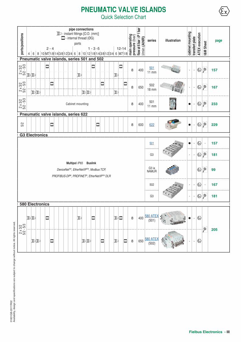
.PNEUMATIC VALVE ISLANDS
Quick Selection Chartpo
rts/
posi
tions
pipe connections* - instant fittings [O.D. (mm)]
w - internal thread (ØG)
mai
n op
erat
ing
pres
sure
(ba
r)flo
w a
t 6 b
ar ∆
P 1
bar
l/min
(A
NR
)
series illustration
cabi
net m
ount
ing
trans
fert
plat
eA
TEX
exec
utio
n
I&M
She
et pageports
2 - 4 1 - 3 -5 12-144 6 8 10 M7 1/8 1/4 3/8 1/2 3/4 6 8 10 12 1/8 1/4 3/8 1/2 3/4 6 M7 1/8
Pneumatic valve islands, series 501 and 502
2 x
3/2
5/2
- 5/3 w w w
8 400501
11 mm- - q 157
** * *
2 x
3/2
5/2
- 5/3 w w w
8 650502
18 mm- - q 167
** ** *
2 x
3/2
5/2
- 5/3
Cabinet mounting 8 400501
11 mm● - q 233
Pneumatic valve islands, series 622
5/2 w w 8 600 622 ● - q 229
G3 Electronics
Multipol IP65 Buslink
DeviceNetTM, EtherNet/IPTM, Modbus TCP,
PROFIBUS-DP®, PROFINET®, EtherNet/IPTM DLR
501 ● - q - 157
G3 - - q 181
G3 ia NAMUR q 99
502 - - q - 167
G3 - - q 181
580 Electronics
2 x
3/2
5/2
- 5/3
** w * w * w 8 400580 ATEX
(501)● - q
205
** w ** w * w 8 650580 ATEX
(502)- - q
IV - Fielbus Electronics
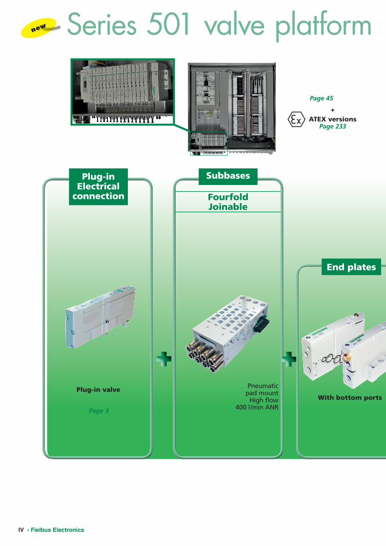
Plug-in Electrical
connection Fourfold Joinable
Subbases
End plates
Pneumatic pad mount
High flow 400 l/min ANR
Plug-in valve With bottom ports
Series 501 valve platform (11 mm)new
Page 3
Page 45
+ATEX versions
Page 233

Fielbus Electronics - V
Valves technology
Assemblies
Multiwire or Fieldbus
I/O Modules
or
Multiwire connection
G3/580 Electronics
I/O Module
Fieldbus
Page 3Valve manifolds
Rubber packed all pneumatic functions including double 3/2 NC and NO
Sandwich Accessories
Plugged between valve and subbase:
Sandwich Speed Control
Shut off
Pressure regulator
Blank station plate
580 Electronics
Page 121
Page 205
ATEX versions +Page 205
580 Electronics
G3
599
580
Series 501 valve platform (11 mm)

VI - Fielbus Electronics
M12 Electrical
connection
Plug-in Electrical
connection
Subbases
Double Joinable
Double Joinable
Single
Subbases
End plates
End plates
M12 ValveISO 15407-1
Pneumatic pad mount
High flow502 : 650 l/min ANR503 : 1400 l/min ANR
Plug-in valve
ISO 15407-2502 : 500 l/min ANR503 : 1200 l/min ANR
With bottom ports
Side ports
Single
new
Pages 259 / 273
Page 16 / 27
ISO 15407-2502 : 500 l/min ANR503 : 1200 l/min ANR
ISO 15407-1502 : 500 l/min ANR503 : 1200 l/min ANR
ISO 15407-1502 : 500 l/min ANR503 : 1200 l/min ANR
Series 502 & 503 valve platform (18 & 26 mm)
Page 293 / 293

Fielbus Electronics - VII
Series 502 & 503 valve platform (18 & 26 mm)Assemblies Valves technology
Assemblies
or
Multiwire connection
G3/580 Electronics
Page 259 / 273
on ISO 15407-1 joinable subbases
I/O Module
Fieldbus
Valve manifolds
Page 287 / 293
on ISO 15407-2 single subbase M12 electrical interface on the subbase
Valve
M12 valves
Rubber packed all pneumatic functions including double 3/2
Spool & Sleeve Very high life time > 200 M cycles
M12 valve on ISO 15407-1 single subbase
Sandwich Accessories
Plugged between valve and subbase: Sandwich Speed Control
Shut off
Exhaust block
Pressure blockPressure regulator
Blank station plate
580 Electronics
Page 121 (502 & 503)
Page 259 / 273
Page 11 / 21
+ ATEX versions (502) Page 205Multiwire or Fieldbus I/O Modules
Multipol ou bus de terrainModules E/S
G3
599
580
SERIES
503
All leaflets are available on: www.asco.com
VIII - Fielbus Electronics
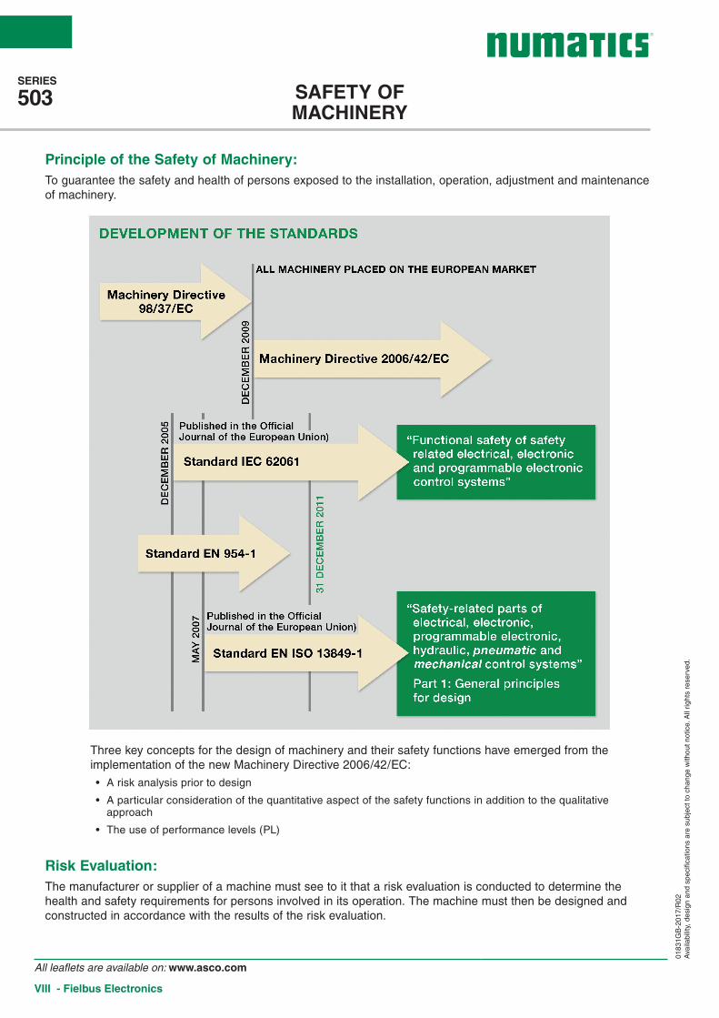
Three key concepts for the design of machinery and their safety functions have emerged from the implementation of the new Machinery Directive 2006/42/EC:
• A risk analysis prior to design
• A particular consideration of the quantitative aspect of the safety functions in addition to the qualitative approach
• The use of performance levels (PL)
Principle of the Safety of Machinery:To guarantee the safety and health of persons exposed to the installation, operation, adjustment and maintenance of machinery.
Risk Evaluation:The manufacturer or supplier of a machine must see to it that a risk evaluation is conducted to determine the health and safety requirements for persons involved in its operation. The machine must then be designed and constructed in accordance with the results of the risk evaluation.
SAFETY OF MACHINERY
0183
1GB
-201
7/R
02A
vaila
bilit
y, d
esig
n an
d sp
ecifi
catio
ns a
re s
ubje
ct to
cha
nge
with
out n
otic
e. A
ll rig
hts
rese
rved
.

SERIES
503
All leaflets are available on: www.asco.com
Fielbus Electronics - IX
“Good engineering practice + probabilistic calculations”
RISK EVALUATION
0183
1GB
-201
7/R
02A
vaila
bilit
y, d
esig
n an
d sp
ecifi
catio
ns a
re s
ubje
ct to
cha
nge
with
out n
otic
e. A
ll rig
hts
rese
rved
.

SERIES
503
All leaflets are available on: www.asco.com
X - Fielbus Electronics
RELIABILITY DATAfor components from manufacturers, standards, databases etc.MTTFd: Mean time to dangerous failure– Value expressed in years
MTTFd
Rating for each channel
Low 3 years < MTTFd < 10 years
Medium 10 years < MTTFd < 30 years
High 30 years < MTTFd < 100 years
B10d: Number of cycles after which 10% of a random sample of wearing components fail dangerously – Value expressed in number of cycles.
DC: Diagnostic Coverage
CCF: Common Cause Failure. Measures to be taken to prevent a given cause (and its effect) from concurrently disabling the multiple channels of a safety circuit.
Mission time T10: In line with “good engineering practice” as recommended in EN ISO 13849-1, components attaining this value must be replaced (precautionary principle).
None Low Medium High
DC < 60% 60% < DC < 90%
90% < DC < 99% 99% < DC
EN/IEC 62061 - EN ISO 13849-1
DESIGN PROCESS
0183
1GB
-201
7/R
02A
vaila
bilit
y, d
esig
n an
d sp
ecifi
catio
ns a
re s
ubje
ct to
cha
nge
with
out n
otic
e. A
ll rig
hts
rese
rved
.

SERIES
503
All leaflets are available on: www.asco.com
Fielbus Electronics - XI
Only the pneumatic part is described in the form of a subsystem in these examples. Other safety-related components (e.g. protective devices, electrical logic elements) must be added to ensure the safety function is complete.
The examples shown here only relate to the stopping of hazardous movements. In pneumatics, safety measures concerning the interruption of energy sources, the evacuation of potential energy (pressure contained in a part of the circuit), and a “progressive” start-up after an unexpected shutdown should not be omitted.
To attain a PL = c, category 1 architecture
• Safety function: Stopping of the potentially hazardous movement of cylinder 1A.
• Functional description:
Input ‘I’: not represented, movable guard or light barrier, etc.Logic element ‘L’: not represented, PLC
• Calculation of the probability of dangerous failure:
1 cycle = 5 s 16 h 240 days 2,764,800 cycles
B10d (1V1A – series 520) = 130,000,000 cycles, i.e. an operating time of 47 years, MTTFd=470 years “high”
By limiting the valve’s operating time to 47 years, this corresponds to a PL = c
PL
a
b
c
d
e
Category BDCavg none
Category 1DCavg none
Category 2DCavg low
Category 2DCavg medium
Category 3DCavg low
Category 3DCavg medium
Category 4DCavg high
PL Performance Levels
MTTFd rating for each channel = low
MTTFd rating for each channel = medium
MTTFd rating for each channel = high
Dangerousmovement
Solenoid valveselected to ensuresafety compliance
Other consumersand control systems
1A
1V 1A
0V 1A
0S1 P
FOR YOUR SAFETY
0183
1GB
-201
7/R
02A
vaila
bilit
y, d
esig
n an
d sp
ecifi
catio
ns a
re s
ubje
ct to
cha
nge
with
out n
otic
e. A
ll rig
hts
rese
rved
.
SERIES
503
All leaflets are available on: www.asco.com
XII - Fielbus Electronics
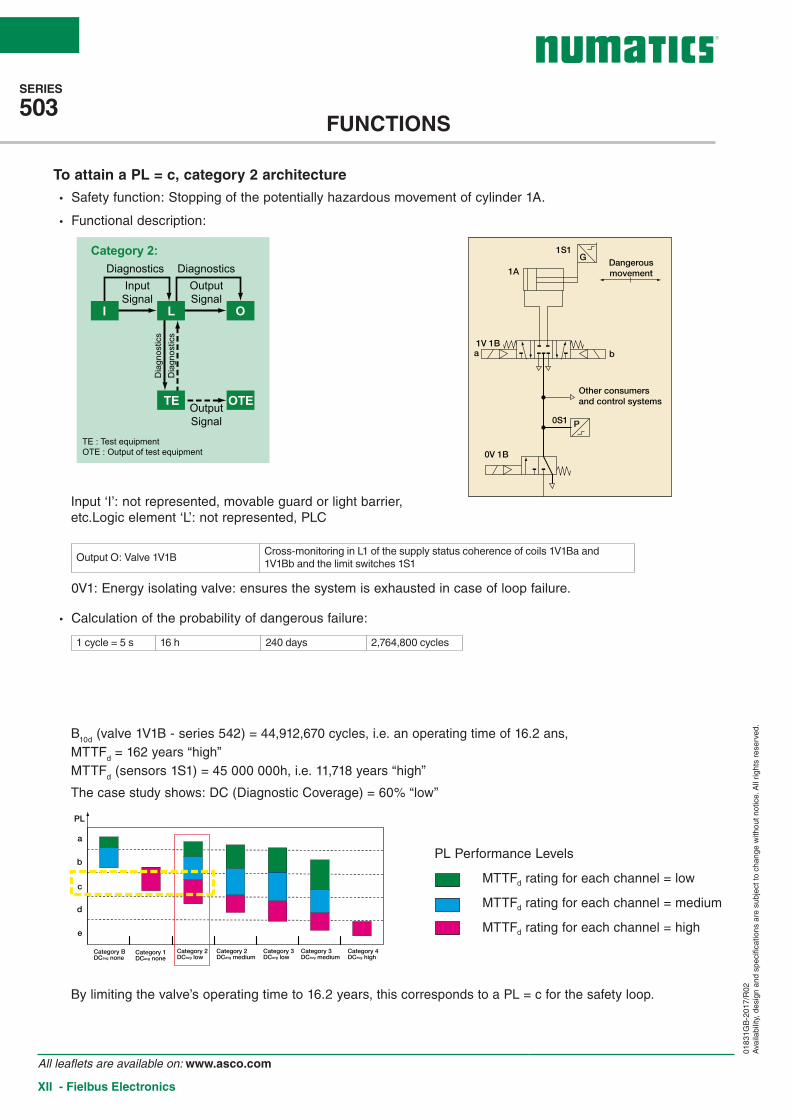
To attain a PL = c, category 2 architecture
• Safety function: Stopping of the potentially hazardous movement of cylinder 1A.
• Functional description:
Input ‘I’: not represented, movable guard or light barrier, etc.Logic element ‘L’: not represented, PLC
Output O: Valve 1V1BCross-monitoring in L1 of the supply status coherence of coils 1V1Ba and 1V1Bb and the limit switches 1S1
0V1: Energy isolating valve: ensures the system is exhausted in case of loop failure.
• Calculation of the probability of dangerous failure:
1 cycle = 5 s 16 h 240 days 2,764,800 cycles
B10d (valve 1V1B - series 542) = 44,912,670 cycles, i.e. an operating time of 16.2 ans, MTTFd = 162 years “high” MTTFd (sensors 1S1) = 45 000 000h, i.e. 11,718 years “high”
The case study shows: DC (Diagnostic Coverage) = 60% “low”
By limiting the valve’s operating time to 16.2 years, this corresponds to a PL = c for the safety loop.
Category 2:
OTETE
I OL
Diagnostics
Dia
gnos
tics
Dia
gnos
tics
DiagnosticsInput
SignalOutputSignal
OutputSignal
TE : Test equipmentOTE : Output of test equipment
PL
a
b
c
d
e
Category BDCavg none
Category 1DCavg none
Category 2DCavg low
Category 2DCavg medium
Category 3DCavg low
Category 3DCavg medium
Category 4DCavg high
PL Performance Levels
MTTFd rating for each channel = low
MTTFd rating for each channel = medium
MTTFd rating for each channel = high
1A
1S1G Dangerous
movement
Other consumersand control systems
0V 1B
0S1 P
1V 1Ba b
FUNCTIONS
0183
1GB
-201
7/R
02A
vaila
bilit
y, d
esig
n an
d sp
ecifi
catio
ns a
re s
ubje
ct to
cha
nge
with
out n
otic
e. A
ll rig
hts
rese
rved
.

SERIES
503
All leaflets are available on: www.asco.com
Fielbus Electronics - XIII
FOR YOUR SAFETY
PL
a
b
c
d
e
Category BDCavg none
Category 1DCavg none
Category 2DCavg low
Category 2DCavg medium
Category 3DCavg low
Category 3DCavg medium
Category 4DCavg high
To attain a PL = d, category 3 architecture
• Safety function: Stopping of the potentially hazardous movement of cylinder 1A.
• Functional description:
Inputs ‘I1’ and ‘I2’: not represented, movable guard or light barrier, etc. Logic elements ‘L1’ and ‘L2’: not represented, PLC
Output O: Valve 1V1BCross-monitoring in L1 of the supply status coherence of coils1V1Ba and 1V1Bb and the limit switches 1S1 Cross-monitoring of L1/L2 status
coherence within the PLCOutput O2: Valve 2V1 controlling the rod lock 2Z1
Pressure switch 2S1 for transmission of signal to L2
0V1B: Energy isolating valve: ensures the system is exhausted.
• Calculation of the probability of dangerous failure:
1 cycle = 10 s 16 h 240 days 1,382,400 cycles
PL Performance Levels
MTTFd rating for each channel = low
MTTFd rating for each channel = medium
MTTFd rating for each channel = high
By limiting the operating time of the pressure switch and rod lock to 2.89 years, this corresponds to a PL = d for the safety loop.
B10d (valve 1V1B - series 542) = 44,912,670 cycles, i.e. an operating time of 32.4 years, MTTFd = 324 years “high”
B10d (valve 2V1 - series 520) = 20,000,000 cycles, i.e. an operating time of 14.5 years, MTTFd = 145 years “high”
B10d (pressure switch 2S1, dynamic rod lock 2Z1) = 4,000,000 cycles, i.e. a mission time of T10 = 2.89 years, MTTFd = 28.9 years “medium”
MTTFd (sensors 1S1) = 45,000,000 h, i.e. 11,718 years “high” The case study shows: DC (Diagnostic Coverage) = 60% “low”, DC (2V1) = 99% “high”, DC* (2Z1) = 75%
i.e. for channel O2, DC = 78% “low”
1A
1S1G
Dangerousmovement
Other consumersand control systems
0V 1B
0S1 P
P
1V 1Ba b
2Z1
2V1
S21
Categories 3 and 4:
I1
I2
L1 O1
L2 O2
Diagnostics
Diagnostics
InputSignal
InputSignal
OutputSignal
OutputSignal
Cro
ss-c
heck
ing
diag
nost
ics
* “ Good engineering practice” methods associate this type of component with a low-to-medium DC to cover any of the component’s drift failures.
0183
1GB
-201
7/R
02A
vaila
bilit
y, d
esig
n an
d sp
ecifi
catio
ns a
re s
ubje
ct to
cha
nge
with
out n
otic
e. A
ll rig
hts
rese
rved
.

SERIES
503
All leaflets are available on: www.asco.com
XIV - Fielbus Electronics
FUNCTIONS
1A
1S1G Dangerous
movement
Other consumersand control systems
0V 1B
0S1 P
1V 1Ba b
PL
a
b
c
d
e
Category BDCavg none
Category 1DCavg none
Category 2DCavg low
Category 2DCavg medium
Category 3DCavg low
Category 3DCavg medium
Category 4DCavg high
To attain a PL = d, category 3 architecture
• Safety function: Stopping of the potentially hazardous movement of cylinder 1A.
• Functional description:
Inputs ‘I1’ and ‘I2’: not represented, movable guard or light barrier, etc. Logic elements ‘L1’ and ‘L2’: not represented, PLC
Output O: Valve 1V1BComparison in L1 of the supply status of coils 1V1Ba and 1V1Bb and the limit switches 1S1 Cross-monitoring of L1/L2 status
coherence within the PLCOutput O2: Valve 2V1 controlling the two 2/2 "cylinder stop" valves used as braking units
Pressure switch 2S1 for transmission of signal to L2
0V1B: Energy isolating valve: ensures the system is exhausted.
• Calculation of the probability of dangerous failure:
1 cycle = 10 s 16 h 240 days 1,382,400 cycles
By limiting the operating time of the pressure switch and rod lock to 2.89 years, this corresponds to a PL = d for the safety loop.
Category 2:
OTETE
I OL
Diagnostics
Dia
gnos
tics
Dia
gnos
tics
DiagnosticsInputSignal
OutputSignal
OutputSignal
TE : Test equipmentOTE : Output of test equipment
B10d (valve 1V1B - series 542) = 44,912,670 cycles, i.e. an operating time of 32.4 years, MTTFd = 324 years “high”
B10d (valve 2V1 - series 520) = 20,000,000 cycles, i.e. an operating time of 14.5 years, MTTFd = 145 years “high”
B10d (pressure switch 2S1, dynamic rod lock 2Z1) = 4,000,000 cycles, i.e. a mission time of T10 = 2.89 years, MTTFd = 28.9 years “medium”
B10d (2/2 cylinder stop valves 2V3, 2V2) = 60,000,000 cycles, i.e. MTTFd = 434 years “high”
The case study shows: DC (1V1B)=60% “low”, DC (2V1)=99% “high”, DC* (2V3, 2V2)=60%, i.e. for channel O2, DC = 78% “low”.
* “ Good engineering practice” methods associate this type of component with a low-to-medium DC to cover any of the component’s drift failures.
PL Performance Levels
MTTFd rating for each channel = low
MTTFd rating for each channel = medium
MTTFd rating for each channel = high
0183
1GB
-201
7/R
02A
vaila
bilit
y, d
esig
n an
d sp
ecifi
catio
ns a
re s
ubje
ct to
cha
nge
with
out n
otic
e. A
ll rig
hts
rese
rved
.