pneumatic fenders: manufacturing methods matter/media/marine--systems/... · the body of a...
TRANSCRIPT

TRELLEBORG MARINE SYSTEMS
Pneumatic Fenders:ManufacturingMethods Matter
A Critical Comparison between Conventional Mold Manufacturing and Airbag Manufacturing
2
AbstractPneumatic fenders are extensively used for ship-to-ship transfers at mid seas, double banking operations, and as vessel-to-berth at dock/jetties.
Supply of high quality and reliable fenders that can perform effectively even under the harshest environmental conditions, is an absolute necessity. It is therefore extremely crucial for each and every pneumatic fender to comply with the ISO 17357-1:2014 standard that ensures they follow the correct manufacturing process. In recent times, pneumatic fenders that are made by adopting airbag manufacturing process are being supplied for uses in many critical applications.
However, such fenders do not usually comply with all of the recommended manufacturing process guidelines and compound properties as specified under the ISO 17357-1:2014 standard. The airbag production method is unable to attain the quality of fenders that can be achieved by using a typical molding process. This paper highlights the differences in the manufacturing process and its impact on the the quality of pneumatic fenders.
3
These days, pneumatic fenders are widely used as protection elements from collision between two vessels in the offshore transfer of oil and other chemicals. It’s critical that while this transfer takes place, the highest levels of safety are maintained.
When fenders are made up of lower quality materials and are not manufactured to the highest standards, they may fail at critical moments such as during the transfer of crude oil in mid-sea exposed locations. Accidents like these can lead to environmental damage and risk the health and safety of working personnel.
The new influx of manufacturers employing airbag production methods for their pneumatic
fenders is a concern for the industry due to the questionable quality levels of their products.
This paper explores the difference in fenders manufactured using the airbag
manufacturing method without employing a mold and fenders
manufactured conventionally using a mold to highlight the impact of the manufacturing process on the performance, safety, and longevity of these pneumatic fenders.
Introduction
Chapters
THE SAFETY OF PNEUMATIC FENDERS
SHIP-TO-SHIP APPLICATIONS 4
FENDER SELECTION PROCESS 5
AIRBAG APPLICATIONS 6
SHIP LAUNCHING AND STS OPERATIONS 7
COMPARING CONFIGURATIONS 8
THE AIRBAG MANUFACTURING PROCESS 10
COMPARING MANUFACTURING PROCESS 12
DISCUSSION ON MANUFACTURING PROCESS 16
THE CONVENTIONAL MANUFACTURING PROCESS 18
AIRBAG MANUFACTURING AND FENDER QUALITY 19
INNER FLANGE DESIGN 25
CONCLUSIONS 26
4
Ship-to-ship
Both primary and secondary fenders are high-pressure
fenders with internal pressures of either
50or80KPa
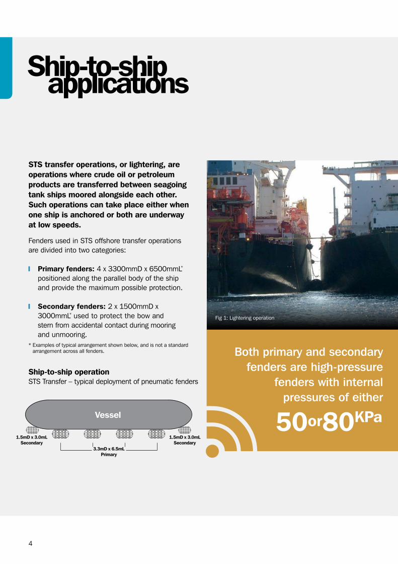
Fig 1: Lightering operation
STS transfer operations, or lightering, are operations where crude oil or petroleum products are transferred between seagoing tank ships moored alongside each other. Such operations can take place either when one ship is anchored or both are underway at low speeds.
Fenders used in STS offshore transfer operations are divided into two categories:
Primary fenders: 4 x 3300mmD x 6500mmL* positioned along the parallel body of the ship and provide the maximum possible protection.
Secondary fenders: 2 x 1500mmD x 3000mmL* used to protect the bow and stern from accidental contact during mooring and unmooring.
* Examples of typical arrangement shown below, and is not a standard arrangement across all fenders.
Ship-to-ship operation STS Transfer – typical deployment of pneumatic fenders
1.5mD x 3.0mL Secondary
3.3mD x 6.5mL Primary
1.5mD x 3.0mL Secondary
applications

5
In STS operations, a pneumatic fender must do the following:
Absorb 5000-6000KJ of energy in rough conditions for some vessels
Create low hull pressures during compression
Generate enough stand-off between vessels even after high compressions (over 60% of the fender’s diameter)
After contact, the discharge ship and the receiving ship usually have different rotational and linear movements. These movements exert huge amounts of shearing forces on the fenders. Therefore, fenders must be able to withstand shear forces even at very high and very low temperatures while maintaining their designated internal pressures.
The expected longevity for these fenders is over 10 years. Fenders must be fitted with a proper safety valve for extra protection in the event the internal pressure shoots up beyond the bursting pressure of the fender body and must be supplied with high quality, high strength accessories including shackles, towing rings, swivels, and chains. These accessories must be of the highest quality to resist sea water corrosion for extended durations.
The Oil Companies International Marine Forum (OCIMF) was formed in April 1970 after the Torrey Canyon incident in 1967, and was a response to the growing public concern about marine pollution, particularly by oil. OCIMF and individual company standards focus on the most important aspect of STS operations, the safe transfer of cargo without risk to the environment or damage to the ships.
ISO 17357-1:2014 standard specifies the material, performance, and dimensions of pneumatic rubber fenders. It also specifies the test and inspection procedures for such fenders. However, it does not address any safety hazards associated with its use. It is the user’s responsibility to establish appropriate safety and health practices and determine the regulatory limitations before using a pneumatic fender. This standard does not address the requirement of manufacturing process in regard to the safety aspect of pneumatic fenders.
STS operations demand the highest levels of safety. Pneumatic fenders are an integral part of safe STS operations and all components of a fender must be able to withstand the rigors of STS operations. The entire operation relies on a few fenders and should any of these fenders fail, it would cause serious damage to the ships as well as to the environment. Therefore, the quality of the fender, the most critical component, cannot be taken lightly.
Fender selectionprocess

6
The launch is one of the most important events in the entire ship’s construction process and if launches are to occur smoothly, every shipyard needs facilities for docking and launching such as a graving dock, a floating dock, and a slipway. These main facilities are known as the initial basic infrastructures of a shipyard and building these facilities require huge investments in time and money.
Airbag systems reduce the need for a large initial investment and make this launching process faster and more cost effective.
Marine rubber airbags are made up of an inflatable giant rubber cylinder with two conical ends.
Airbags are first inserted underneath the ship and inflated. The airbags provide support to the hull of the ship and rolling these airbags launches a vessel into the water.
This process is simpler, more economical and arguably safer than other options such as sideways launching.
Depending on the size and shape of a ship, the ship may either be launched by the end launching method or by the side launching method.
There are three ways to arrange airbags when using the end launching method:
The best arrangement for the end launching method varies based on the ship’s width and the length of the airbags.
Airbagapplications
Fig 2: Launch of the passenger liner “Empress of Canada” in 1960 using a proper launching facility.
7
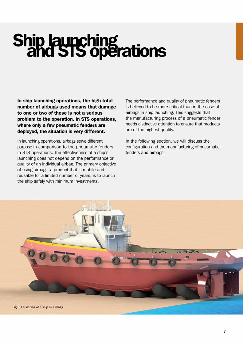
In ship launching operations, the high total number of airbags used means that damage to one or two of these is not a serious problem to the operation. In STS operations, where only a few pneumatic fenders are deployed, the situation is very different.
In launching operations, airbags serve different purpose in comparison to the pneumatic fenders in STS operations. The effectiveness of a ship’s launching does not depend on the performance or quality of an individual airbag. The primary objective of using airbags, a product that is mobile and reusable for a limited number of years, is to launch the ship safely with minimum investments.
Ship launchingand STS operations
The performance and quality of pneumatic fenders is believed to be more critical than in the case of airbags in ship launching. This suggests that the manufacturing process of a pneumatic fender needs distinctive attention to ensure that products are of the highest quality.
In the following section, we will discuss the configuration and the manufacturing of pneumatic fenders and airbags.
Fig 3: Launching of a ship by airbags
8
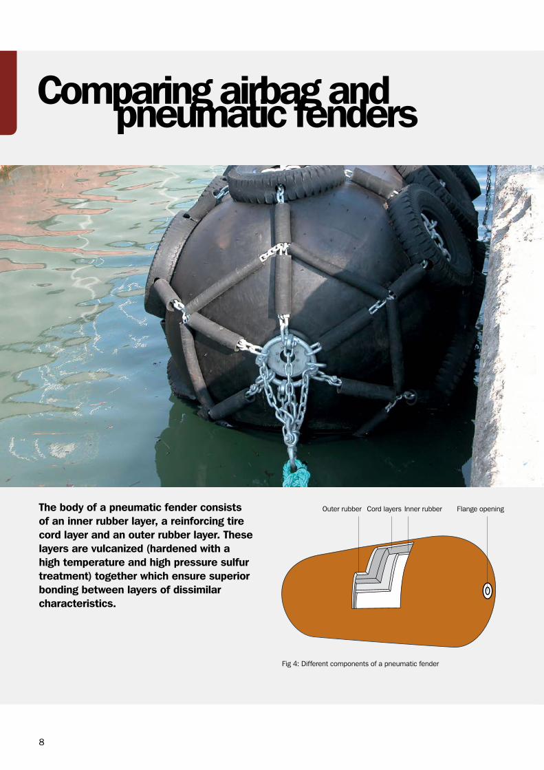
The body of a pneumatic fender consists of an inner rubber layer, a reinforcing tire cord layer and an outer rubber layer. These layers are vulcanized (hardened with a high temperature and high pressure sulfur treatment) together which ensure superior bonding between layers of dissimilar characteristics.
Fig 4: Different components of a pneumatic fender
Comparing airbag andpneumatic fenders
Outer rubber Inner rubber Flange openingCord layers
9
Although the configuration of an airbag is similar to the configuration of a pneumatic fender, there is an immense difference in their manufacturing processes. In the following section, we will discuss the manufacturing of airbags.
COMPONENTS PNEUMATIC FENDERS / AIRBAGS
Outer rubber layer The rubber compound of the outer skin must withstand strenuous use, inclusive of abrasion during adverse weather conditions, while also protecting the tire cord and inner rubber layers.
The chemical composition and the thickness of this layer are extremely crucial in achieving these performance related requirements.
Reinforcing layer (cord layers)
The synthetic tire cord layers should be arranged at an optimum angle to distribute the load and stress evenly during compression and shearing of the fenders.
This is the layer that provides the strength and the fatigue resistance of a fender.
The number of layers required is calculated using different factors such as the thickness of the tire cord, the properties of the tire cords (like the strength and elongation at break), and the angles between the two plies.
A greater number of layers do not necessarily impart more strength. Instead, factors like the angle between the layers will determine the maximum strength of the fender body. An optimally designed fender will have minimum number of layers but maximum body strength.
Inner rubber layer The inner rubber compound is formulated to prevent air leakage through a fender’s body.
Both pneumatic fenders and airbags have components in common that demands certain properties as shown in the following table:
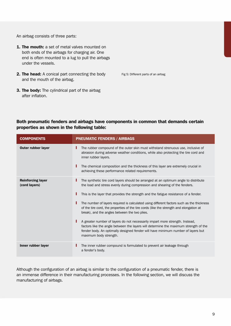
An airbag consists of three parts:
1. The mouth: a set of metal valves mounted on both ends of the airbags for charging air. One end is often mounted to a lug to pull the airbags under the vessels.
2. The head: A conical part connecting the body and the mouth of the airbag.
3. The body: The cylindrical part of the airbag after inflation.
Fig 5: Different parts of an airbag
10
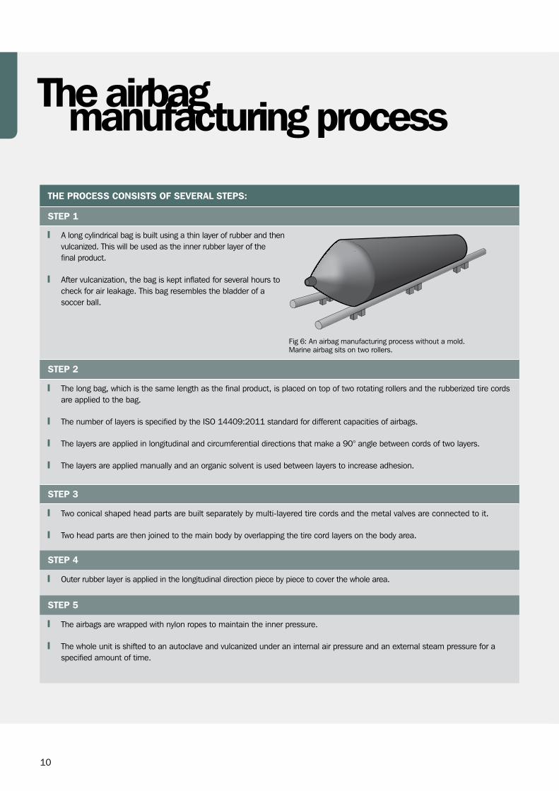
THE PROCESS CONSISTS OF SEVERAL STEPS:
STEP 1
A long cylindrical bag is built using a thin layer of rubber and then vulcanized. This will be used as the inner rubber layer of the final product.
After vulcanization, the bag is kept inflated for several hours to check for air leakage. This bag resembles the bladder of a soccer ball.
STEP 2
The long bag, which is the same length as the final product, is placed on top of two rotating rollers and the rubberized tire cords are applied to the bag.
The number of layers is specified by the ISO 14409:2011 standard for different capacities of airbags.
The layers are applied in longitudinal and circumferential directions that make a 90° angle between cords of two layers.
The layers are applied manually and an organic solvent is used between layers to increase adhesion.
STEP 3
Two conical shaped head parts are built separately by multi-layered tire cords and the metal valves are connected to it.
Two head parts are then joined to the main body by overlapping the tire cord layers on the body area.
STEP 4
Outer rubber layer is applied in the longitudinal direction piece by piece to cover the whole area.
STEP 5
The airbags are wrapped with nylon ropes to maintain the inner pressure.
The whole unit is shifted to an autoclave and vulcanized under an internal air pressure and an external steam pressure for a specified amount of time.
Fig 6: An airbag manufacturing process without a mold. Marine airbag sits on two rollers.
manufacturing processThe airbag
11
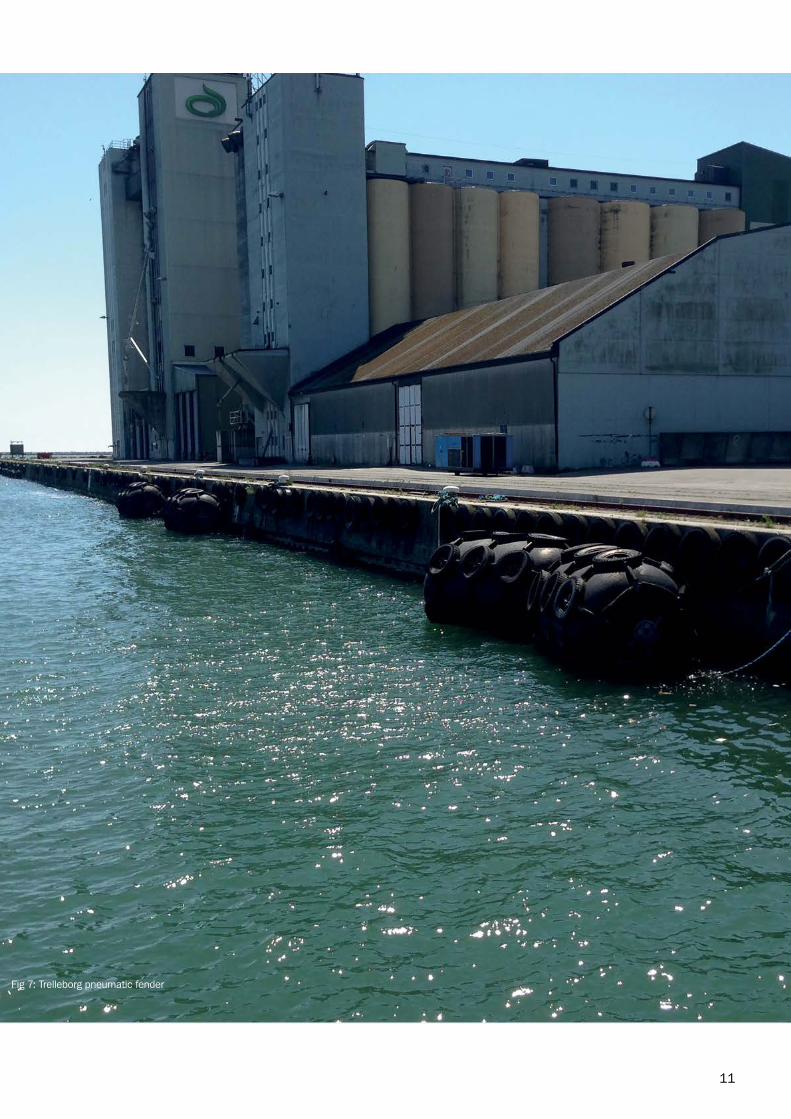
Fig 7: Trelleborg pneumatic fender
12
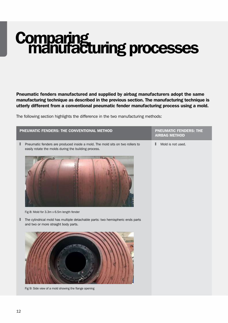
Pneumatic fenders manufactured and supplied by airbag manufacturers adopt the same manufacturing technique as described in the previous section. The manufacturing technique is utterly different from a conventional pneumatic fender manufacturing process using a mold.
The following section highlights the difference in the two manufacturing methods:
PNEUMATIC FENDERS: THE CONVENTIONAL METHOD PNEUMATIC FENDERS: THE AIRBAG METHOD
Pneumatic fenders are produced inside a mold. The mold sits on two rollers to easily rotate the molds during the building process.
Fig 8: Mold for 3.3m x 6.5m length fender
The cylindrical mold has multiple detachable parts: two hemispheric ends parts and two or more straight body parts.
Fig 9: Side view of a mold showing the flange opening
Mold is not used.
Comparingmanufacturing processes
13
PNEUMATIC FENDERS: THE CONVENTIONAL METHOD PNEUMATIC FENDERS: THE AIRBAG METHOD
STEP 1 STEP 1
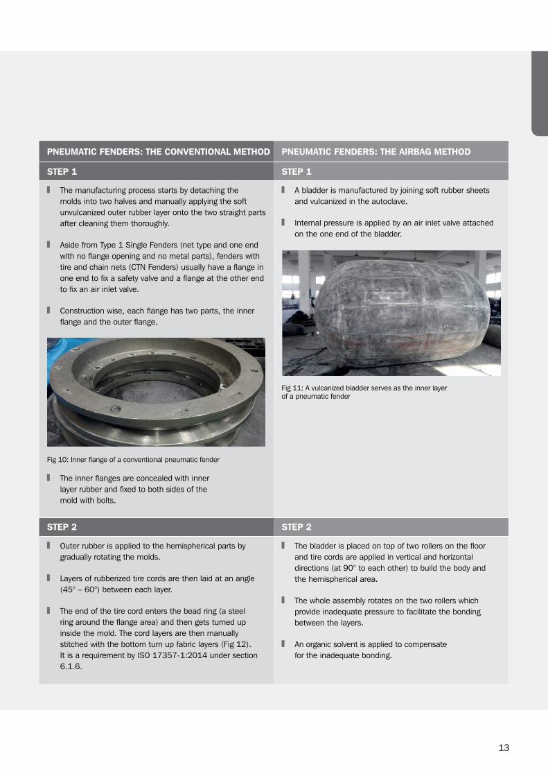
The manufacturing process starts by detaching the molds into two halves and manually applying the soft unvulcanized outer rubber layer onto the two straight parts after cleaning them thoroughly.
Aside from Type 1 Single Fenders (net type and one end with no flange opening and no metal parts), fenders with tire and chain nets (CTN Fenders) usually have a flange in one end to fix a safety valve and a flange at the other end to fix an air inlet valve.
Construction wise, each flange has two parts, the inner flange and the outer flange.
Fig 10: Inner flange of a conventional pneumatic fender
The inner flanges are concealed with inner layer rubber and fixed to both sides of the mold with bolts.
A bladder is manufactured by joining soft rubber sheets and vulcanized in the autoclave.
Internal pressure is applied by an air inlet valve attached on the one end of the bladder.
Fig 11: A vulcanized bladder serves as the inner layer of a pneumatic fender
STEP 2 STEP 2
Outer rubber is applied to the hemispherical parts by gradually rotating the molds.
Layers of rubberized tire cords are then laid at an angle (45° – 60°) between each layer.
The end of the tire cord enters the bead ring (a steel ring around the flange area) and then gets turned up inside the mold. The cord layers are then manually stitched with the bottom turn up fabric layers (Fig 12). It is a requirement by ISO 17357-1:2014 under section 6.1.6.
The bladder is placed on top of two rollers on the floor and tire cords are applied in vertical and horizontal directions (at 90° to each other) to build the body and the hemispherical area.
The whole assembly rotates on the two rollers which provide inadequate pressure to facilitate the bonding between the layers.
An organic solvent is applied to compensate for the inadequate bonding.
14
PNEUMATIC FENDERS: THE CONVENTIONAL METHOD PNEUMATIC FENDERS: THE AIRBAG METHOD
STEP 2 STEP 2
Fig 12: Location of the bead ring for the turn up of tire cords.
Fig 14: Tire cord layers are applied on the bladder at 90°
STEP 3 STEP 3
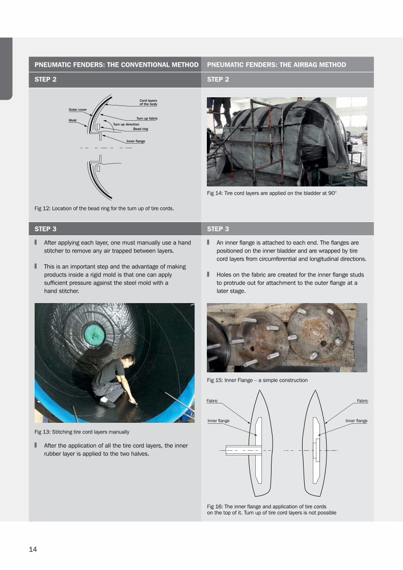
After applying each layer, one must manually use a hand stitcher to remove any air trapped between layers.
This is an important step and the advantage of making products inside a rigid mold is that one can apply sufficient pressure against the steel mold with a hand stitcher.
Fig 13: Stitching tire cord layers manually
After the application of all the tire cord layers, the inner rubber layer is applied to the two halves.
An inner flange is attached to each end. The flanges are positioned on the inner bladder and are wrapped by tire cord layers from circumferential and longitudinal directions.
Holes on the fabric are created for the inner flange studs to protrude out for attachment to the outer flange at a later stage.
Fig 15: Inner Flange – a simple construction
Fig 16: The inner flange and application of tire cords on the top of it. Turn up of tire cord layers is not possible
15
PNEUMATIC FENDERS: THE CONVENTIONAL METHOD PNEUMATIC FENDERS: THE AIRBAG METHOD
STEP 4 STEP 4
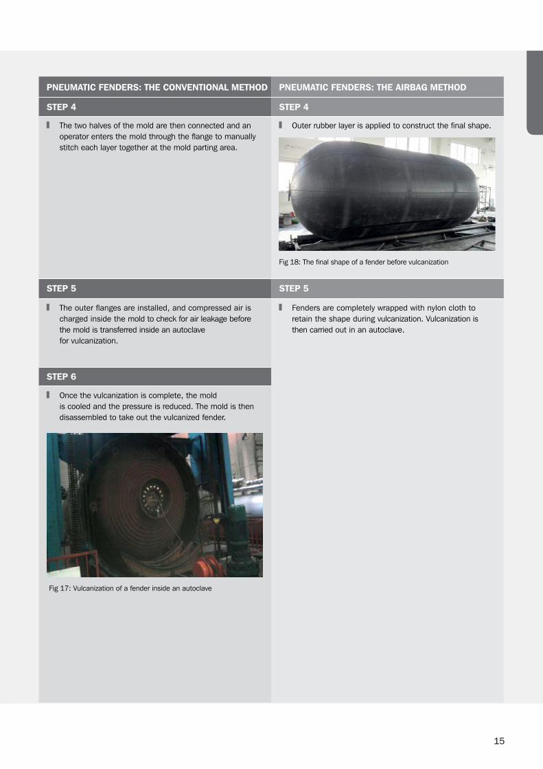
The two halves of the mold are then connected and an operator enters the mold through the flange to manually stitch each layer together at the mold parting area.
Outer rubber layer is applied to construct the final shape.
Fig 18: The final shape of a fender before vulcanization
STEP 5 STEP 5
The outer flanges are installed, and compressed air is charged inside the mold to check for air leakage before the mold is transferred inside an autoclave for vulcanization.
Fenders are completely wrapped with nylon cloth to retain the shape during vulcanization. Vulcanization is then carried out in an autoclave.
STEP 6
Once the vulcanization is complete, the mold is cooled and the pressure is reduced. The mold is then disassembled to take out the vulcanized fender.
Fig 17: Vulcanization of a fender inside an autoclave

16
Pneumatic fenders are built by laying rubber sheet and rubberized fabric layers one over the other. These components have different elongation characteristics. Preassembling of all these components is vital to convert them into a single unit after cure.
This is best achieved by building products inside a mold. The airbag production method of building fenders is unable to achieve rigidity of components due to the limitations associated with the process.
The following table shows the key differences between the conventional production method and the airbag production method.
Discussion on manufacturing process
17
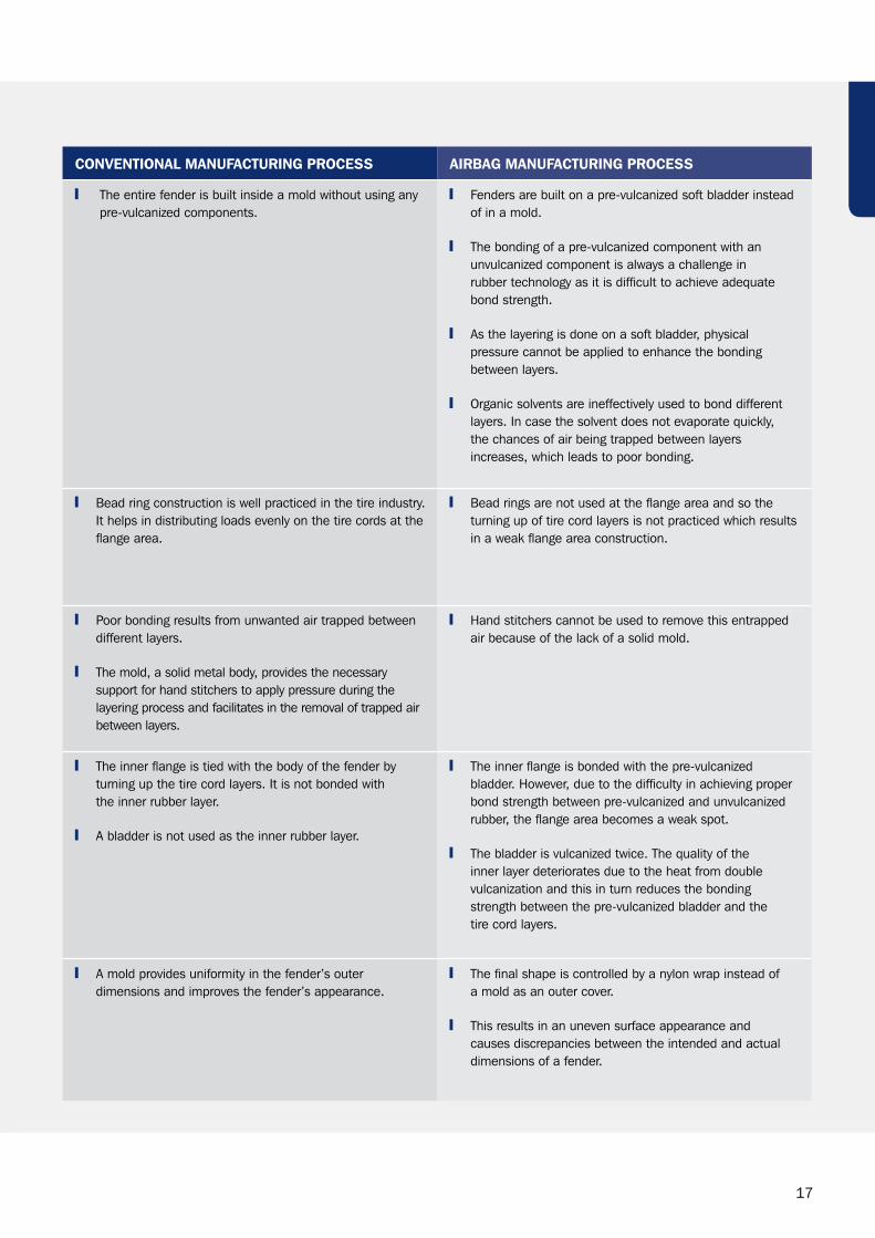
CONVENTIONAL MANUFACTURING PROCESS AIRBAG MANUFACTURING PROCESS
The entire fender is built inside a mold without using any pre-vulcanized components.
Fenders are built on a pre-vulcanized soft bladder instead of in a mold.
The bonding of a pre-vulcanized component with an unvulcanized component is always a challenge in rubber technology as it is difficult to achieve adequate bond strength.
As the layering is done on a soft bladder, physical pressure cannot be applied to enhance the bonding between layers.
Organic solvents are ineffectively used to bond different layers. In case the solvent does not evaporate quickly, the chances of air being trapped between layers increases, which leads to poor bonding.
Bead ring construction is well practiced in the tire industry. It helps in distributing loads evenly on the tire cords at the flange area.
Bead rings are not used at the flange area and so the turning up of tire cord layers is not practiced which results in a weak flange area construction.
Poor bonding results from unwanted air trapped between different layers.
The mold, a solid metal body, provides the necessary support for hand stitchers to apply pressure during the layering process and facilitates in the removal of trapped air between layers.
Hand stitchers cannot be used to remove this entrapped air because of the lack of a solid mold.
The inner flange is tied with the body of the fender by turning up the tire cord layers. It is not bonded with the inner rubber layer.
A bladder is not used as the inner rubber layer.
The inner flange is bonded with the pre-vulcanized bladder. However, due to the difficulty in achieving proper bond strength between pre-vulcanized and unvulcanized rubber, the flange area becomes a weak spot.
The bladder is vulcanized twice. The quality of the inner layer deteriorates due to the heat from double vulcanization and this in turn reduces the bonding strength between the pre-vulcanized bladder and the tire cord layers.
A mold provides uniformity in the fender’s outer dimensions and improves the fender’s appearance.
The final shape is controlled by a nylon wrap instead of a mold as an outer cover.
This results in an uneven surface appearance and causes discrepancies between the intended and actual dimensions of a fender.
18
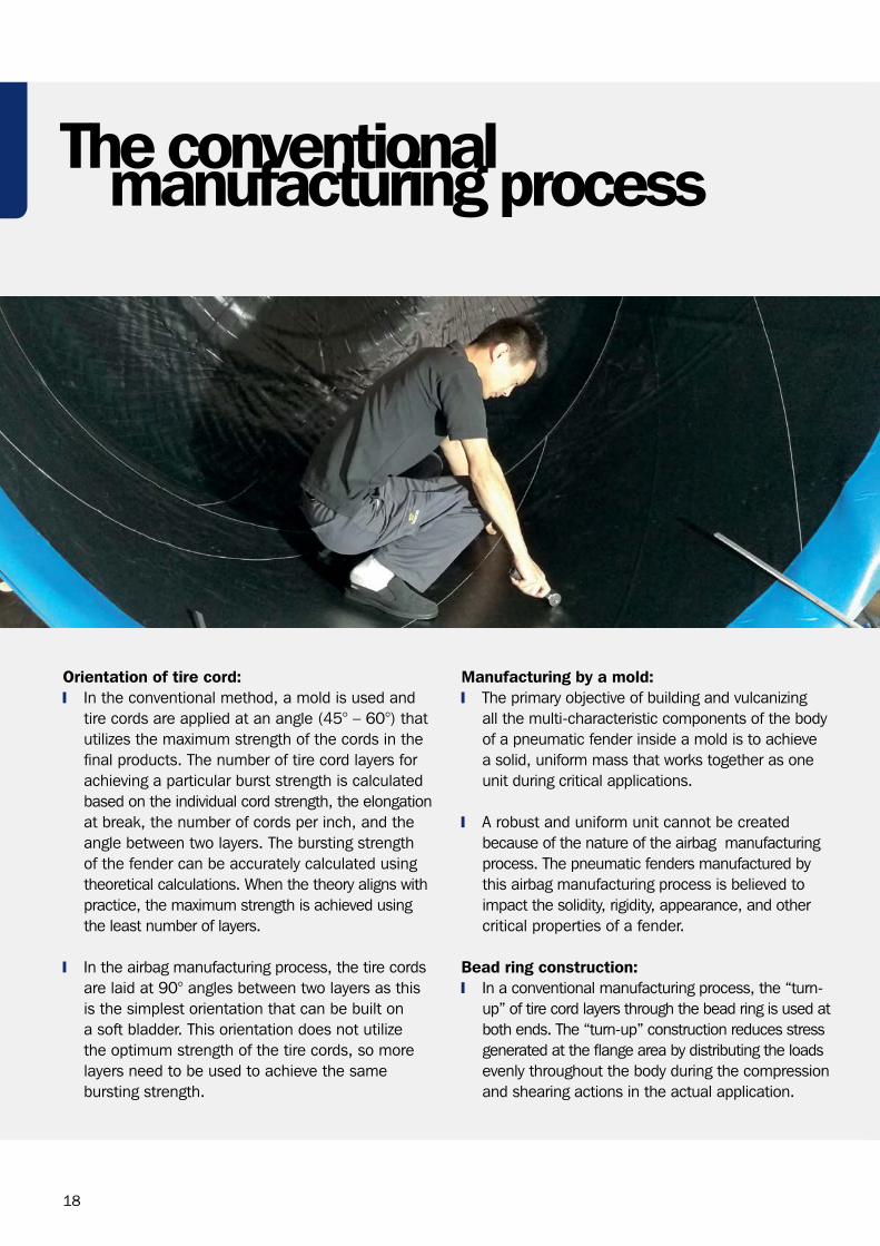
Orientation of tire cord: In the conventional method, a mold is used and
tire cords are applied at an angle (45° – 60°) that utilizes the maximum strength of the cords in the final products. The number of tire cord layers for achieving a particular burst strength is calculated based on the individual cord strength, the elongation at break, the number of cords per inch, and the angle between two layers. The bursting strength of the fender can be accurately calculated using theoretical calculations. When the theory aligns with practice, the maximum strength is achieved using the least number of layers.
In the airbag manufacturing process, the tire cords are laid at 90° angles between two layers as this is the simplest orientation that can be built on a soft bladder. This orientation does not utilize the optimum strength of the tire cords, so more layers need to be used to achieve the same bursting strength.
Manufacturing by a mold: The primary objective of building and vulcanizing
all the multi-characteristic components of the body of a pneumatic fender inside a mold is to achieve a solid, uniform mass that works together as one unit during critical applications.
A robust and uniform unit cannot be created because of the nature of the airbag manufacturing process. The pneumatic fenders manufactured by this airbag manufacturing process is believed to impact the solidity, rigidity, appearance, and other critical properties of a fender.
Bead ring construction: In a conventional manufacturing process, the “turn-
up” of tire cord layers through the bead ring is used at both ends. The “turn-up” construction reduces stress generated at the flange area by distributing the loads evenly throughout the body during the compression and shearing actions in the actual application.
The conventionalmanufacturing process

19
Several 3300 OD x 6500mmL fenders manufactured by the airbag method were investigated.
Many tests such as dimensional checks, performance tests, material tests, bursting tests, etc. were conducted.
Represents pneumatic fenders manufactured by Airbag
Manufacturer #1
Represents pneumatic fenders manufactured by Airbag
Manufacturer #2
Represents pneumatic fenders manufactured by traditional
pneumatic fender manufacturers
PNE (Airbag1) PNE (Airbag2) PNE (Mold)
Airbag manufacturingand fender quality
Fig 19: Appearance of the fender body (Airbags 1 & 2 – uneven and rough surface, Mold – even and smooth surface)
The table and images below show the key differences in surface appearance between the fenders manufactured with the airbag method and the fender manufactured using the conventional mold method:
A greater body weight indicates that the tire cord plies were thicker, and more were used.
Manufacturing fenders without using a mold will result in a fender body with uneven and rough surface.
APPEARANCE WEIGHT (KG) SIZE (DIAMETER X LENGTH IN M)
PNE (Airbag 1) Rough, uneven 1940 3.3 x 6.5
PNE (Airbag 2) Rough, uneven 2250 3.3 x 6.5
PNE (Mold) Smooth, even 1740 3.3 x 6.5
Appearance of the Fender Body:
PNE (AIRBAG 1) PNE (MOLD)PNE (AIRBAG 2)
20
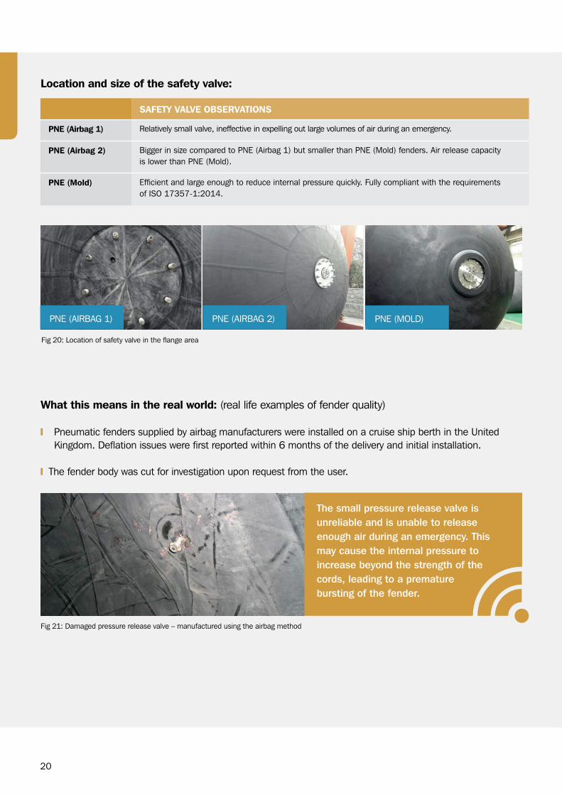
What this means in the real world: (real life examples of fender quality)
Pneumatic fenders supplied by airbag manufacturers were installed on a cruise ship berth in the United Kingdom. Deflation issues were first reported within 6 months of the delivery and initial installation.
The fender body was cut for investigation upon request from the user.
Fig 21: Damaged pressure release valve – manufactured using the airbag method
The small pressure release valve is unreliable and is unable to release enough air during an emergency. This may cause the internal pressure to increase beyond the strength of the cords, leading to a premature bursting of the fender.
Fig 20: Location of safety valve in the flange area
SAFETY VALVE OBSERVATIONS
PNE (Airbag 1) Relatively small valve, ineffective in expelling out large volumes of air during an emergency.
PNE (Airbag 2) Bigger in size compared to PNE (Airbag 1) but smaller than PNE (Mold) fenders. Air release capacity is lower than PNE (Mold).
PNE (Mold) Efficient and large enough to reduce internal pressure quickly. Fully compliant with the requirements of ISO 17357-1:2014.
Location and size of the safety valve:
PNE (AIRBAG 1) PNE (AIRBAG 2) PNE (MOLD)
21
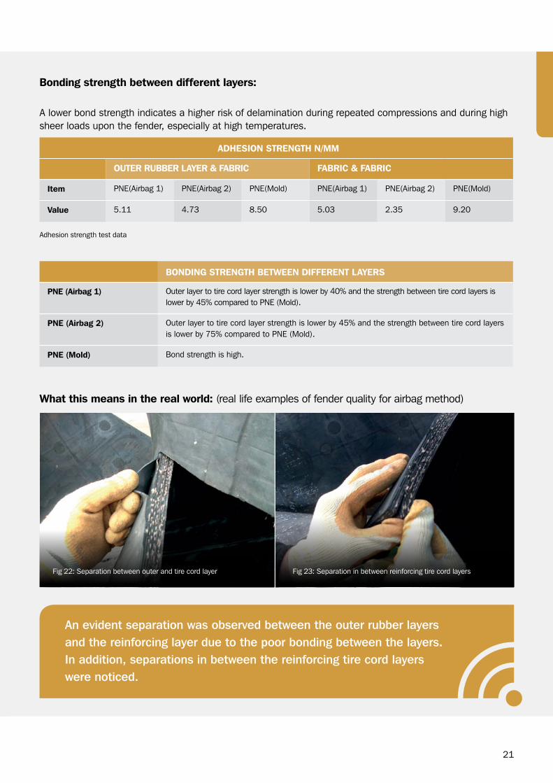
Adhesion strength test data
BONDING STRENGTH BETWEEN DIFFERENT LAYERS
PNE (Airbag 1) Outer layer to tire cord layer strength is lower by 40% and the strength between tire cord layers is lower by 45% compared to PNE (Mold).
PNE (Airbag 2) Outer layer to tire cord layer strength is lower by 45% and the strength between tire cord layers is lower by 75% compared to PNE (Mold).
PNE (Mold) Bond strength is high.
ADHESION STRENGTH N/MM
OUTER RUBBER LAYER & FABRIC FABRIC & FABRIC
Item PNE(Airbag 1) PNE(Airbag 2) PNE(Mold) PNE(Airbag 1) PNE(Airbag 2) PNE(Mold)
Value 5.11 4.73 8.50 5.03 2.35 9.20
A lower bond strength indicates a higher risk of delamination during repeated compressions and during high sheer loads upon the fender, especially at high temperatures.
Bonding strength between different layers:
What this means in the real world: (real life examples of fender quality for airbag method)
An evident separation was observed between the outer rubber layers and the reinforcing layer due to the poor bonding between the layers. In addition, separations in between the reinforcing tire cord layers were noticed.
Fig 23: Separation in between reinforcing tire cord layers Fig 22: Separation between outer and tire cord layer
22
OUTER RUBBER LAYER INNER RUBBER
Item PNE (Airbag 1)
PNE (Airbag 2)
PNE (Mold)
ISO 17357-1:2014
PNE (Airbag 1)
PNE (Airbag 2)
PNE (Mold)
ISO 17357-1:2014
Hardness 64 46 67 60±10 59 44 56 50±10
Tear (N/mm) 614.0 111.2 576.0 ≥400 - - - NA
Thickness (mm) 2 4.13 5 NA 2.88 1.84 5 NA
Density (g/cc) 1.214 1.082 1.129 NA 1.235 1.172 1.110 NA
Physical properties of inner and outer rubber compounds
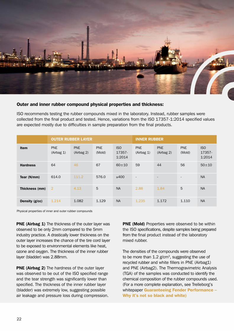
ISO recommends testing the rubber compounds mixed in the laboratory. Instead, rubber samples were collected from the final product and tested. Hence, variations from the ISO 17357-1:2014 specified values are expected mostly due to difficulties in sample preparation from the final products.
Outer and inner rubber compound physical properties and thickness:
PNE (Mold) Properties were observed to be within the ISO specifications, despite samples being prepared from the final product instead of the laboratory mixed rubber.
The densities of the compounds were observed to be more than 1.2 g/cm3, suggesting the use of recycled rubber and white fillers in PNE (Airbag1) and PNE (Airbag2). The Thermogravimetric Analysis (TGA) of the samples was conducted to identify the chemical composition of the rubber compounds used. (For a more complete explanation, see Trelleborg’s whitepaper Guaranteeing Fender Performance – Why it’s not so black and white)
PNE (Airbag 1) The thickness of the outer layer was observed to be only 2mm compared to the 5mm industry practice. A drastically lower thickness on the outer layer increases the chance of the tire cord layer to be exposed to environmental elements like heat, ozone and oxygen. The thickness of the inner rubber layer (bladder) was 2.88mm.
PNE (Airbag 2) The hardness of the outer layer was observed to be out of the ISO specified range and the tear strength was significantly lower than specified. The thickness of the inner rubber layer (bladder) was extremely low, suggesting possible air leakage and pressure loss during compression.
23
OUTER RUBBER LAYER & FABRIC FABRIC & FABRIC
Item PNE(Airbag 1) PNE(Airbag 2) PNE(Mold) PNE(Airbag 1) PNE(Airbag 2) PNE(Mold)
Polymer (%) 47.6 59.6 53 46 52 55
Carbon Black (%)
21.9 28 29.7 19.5 16.4 27.6
Calcium Carbonate (%)
11.6 - - 15.5 7.9 -
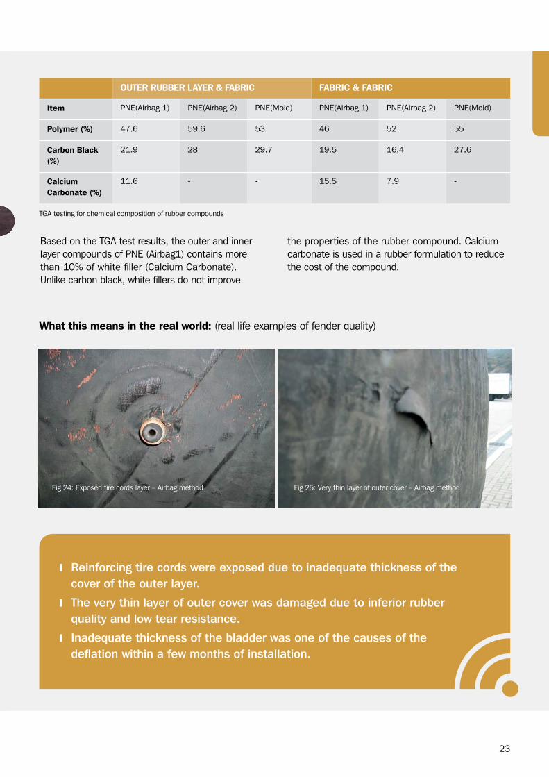
TGA testing for chemical composition of rubber compounds
Based on the TGA test results, the outer and inner layer compounds of PNE (Airbag1) contains more than 10% of white filler (Calcium Carbonate). Unlike carbon black, white fillers do not improve
the properties of the rubber compound. Calcium carbonate is used in a rubber formulation to reduce the cost of the compound.
Fig 25: Very thin layer of outer cover – Airbag methodFig 24: Exposed tire cords layer – Airbag method
What this means in the real world: (real life examples of fender quality)
Reinforcing tire cords were exposed due to inadequate thickness of the cover of the outer layer.
The very thin layer of outer cover was damaged due to inferior rubber quality and low tear resistance.
Inadequate thickness of the bladder was one of the causes of the deflation within a few months of installation.
24
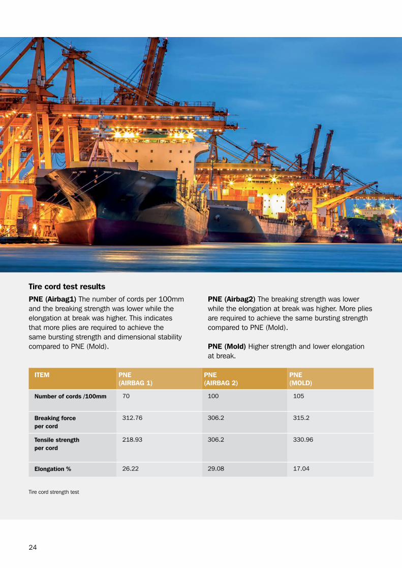
PNE (Airbag1) The number of cords per 100mm and the breaking strength was lower while the elongation at break was higher. This indicates that more plies are required to achieve the same bursting strength and dimensional stability compared to PNE (Mold).
PNE (Airbag2) The breaking strength was lower while the elongation at break was higher. More plies are required to achieve the same bursting strength compared to PNE (Mold).
PNE (Mold) Higher strength and lower elongation at break.
ITEM PNE (AIRBAG 1)
PNE (AIRBAG 2)
PNE (MOLD)
Number of cords /100mm 70 100 105
Breaking force per cord
312.76 306.2 315.2
Tensile strength per cord
218.93 306.2 330.96
Elongation % 26.22 29.08 17.04
Tire cord strength test
Tire cord test results
25
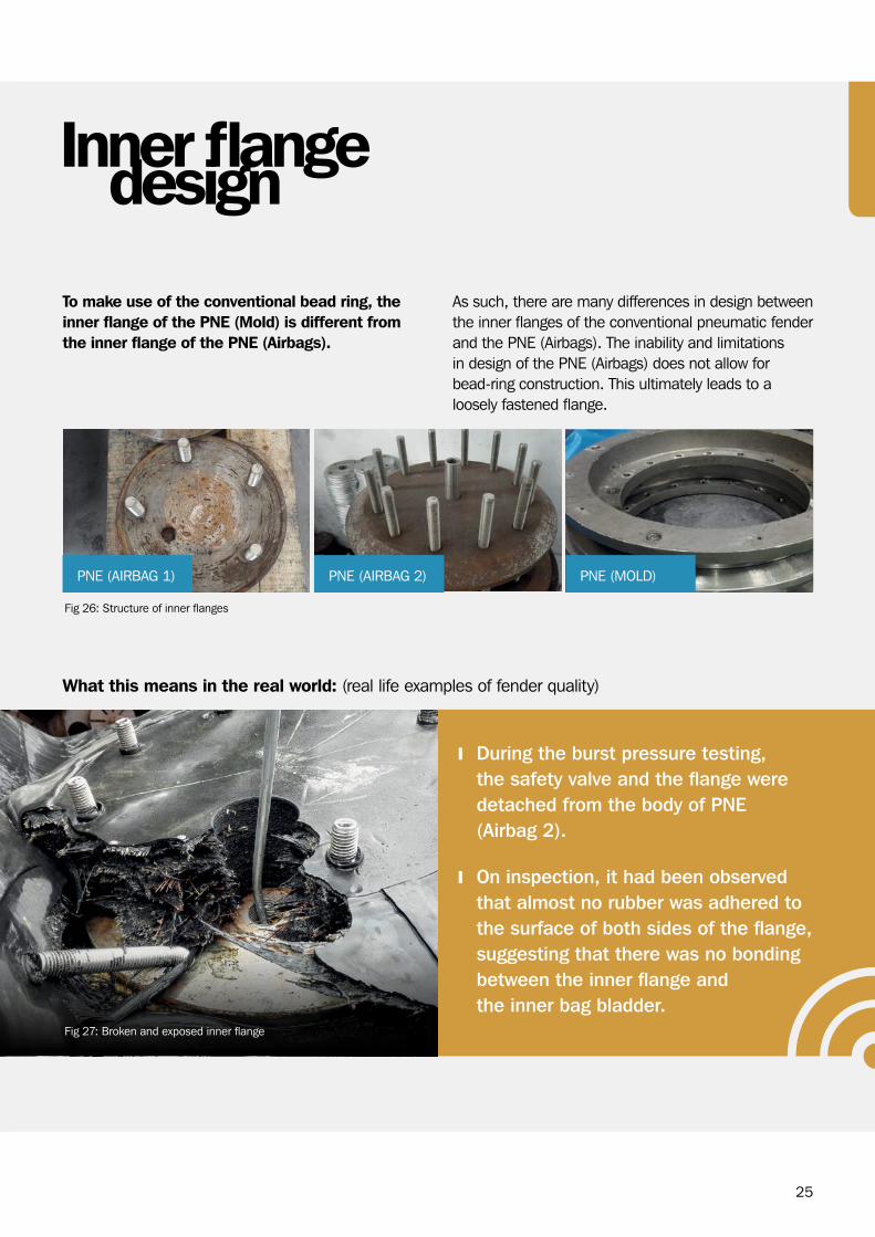
To make use of the conventional bead ring, the inner flange of the PNE (Mold) is different from the inner flange of the PNE (Airbags).
As such, there are many differences in design between the inner flanges of the conventional pneumatic fender and the PNE (Airbags). The inability and limitations in design of the PNE (Airbags) does not allow for bead-ring construction. This ultimately leads to a loosely fastened flange.
What this means in the real world: (real life examples of fender quality)
During the burst pressure testing, the safety valve and the flange were detached from the body of PNE (Airbag 2).
On inspection, it had been observed that almost no rubber was adhered to the surface of both sides of the flange, suggesting that there was no bonding between the inner flange and the inner bag bladder.
Fig 26: Structure of inner flanges
Inner flangedesign
Fig 27: Broken and exposed inner flange
PNE (AIRBAG 1) PNE (AIRBAG 2) PNE (MOLD)
26
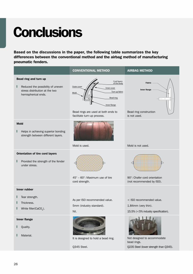
Based on the discussions in the paper, the following table summarizes the key differences between the conventional method and the airbag method of manufacturing pneumatic fenders.
Conclusions
CONVENTIONAL METHOD AIRBAG METHOD
Bead ring and turn up Reduced the possibility of uneven
stress distribution at the two hemispherical ends.
Bead rings are used at both ends to facilitate turn-up process.
Bead ring construction is not used.
Mold Helps in achieving superior bonding
strength between different layers.
Mold is used. Mold is not used.
Orientation of tire cord layers Provided the strength of the fender
under stress.
45° – 60°: Maximum use of tire cord strength.
90°: Chafer cord orientation (not recommended by ISO).
Inner rubber
Tear strength.
Thickness.
White filler(CaC03).
As per ISO recommended value.
5mm (industry standard).
Nil.
< ISO recommended value.
1.84mm (very thin).
15.5% (<5% industry specification).
Inner flange
Quality.
Material.It is designed to hold a bead ring.
Q345 Steel.
Not designed to accommodate bead rings.
Q235 Steel (lower strength than Q345).
Fabric
Inner flange
27
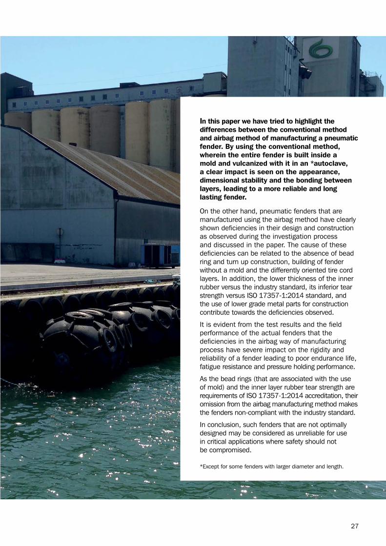
In this paper we have tried to highlight the differences between the conventional method and airbag method of manufacturing a pneumatic fender. By using the conventional method, wherein the entire fender is built inside a mold and vulcanized with it in an *autoclave, a clear impact is seen on the appearance, dimensional stability and the bonding between layers, leading to a more reliable and long lasting fender.
On the other hand, pneumatic fenders that are manufactured using the airbag method have clearly shown deficiencies in their design and construction as observed during the investigation process and discussed in the paper. The cause of these deficiencies can be related to the absence of bead ring and turn up construction, building of fender without a mold and the differently oriented tire cord layers. In addition, the lower thickness of the inner rubber versus the industry standard, its inferior tear strength versus ISO 17357-1:2014 standard, and the use of lower grade metal parts for construction contribute towards the deficiencies observed.
It is evident from the test results and the field performance of the actual fenders that the deficiencies in the airbag way of manufacturing process have severe impact on the rigidity and reliability of a fender leading to poor endurance life, fatigue resistance and pressure holding performance.
As the bead rings (that are associated with the use of mold) and the inner layer rubber tear strength are requirements of ISO 17357-1:2014 accreditation, their omission from the airbag manufacturing method makes the fenders non-compliant with the industry standard.
In conclusion, such fenders that are not optimally designed may be considered as unreliable for use in critical applications where safety should not be compromised.
*Except for some fenders with larger diameter and length.

Fender Systems | Docking & Mooring | Ship-Shore Links | Ship Performance Monitoring | Navigation & Piloting
WWW.TRELLEBORG.COM/MARINE
Trelleborg Marine SystemsEmail: [email protected]
facebook: TrelleborgMarinetwitter: @MarineInsights
youtube.com/user/TrelleborgMarineflickr.com/photos/MarineInsights
linkedin.com/MarineInsights MarineInsightsBlog.Trelleborg.com
Trelleborg is a world leader in engineered polymer solutions that seal, damp and protect critical applications in demanding environments. Its innovative solutions accelerate performance for customers in a sustainable way.