pluse-to-pulsebeammodulationfor4storagerings ... ·...
TRANSCRIPT
PLUSE-TO-PULSE BEAM MODULATION FOR 4 STORAGE RINGSWITH 64 PULSED MAGNETS
Y. Enomoto∗, K. Furukawa, T. Kamitani, F. Miyahara, T. Natsui,M. Satoh, K. Yokoyama, M. Yoshida, KEK, Tsukuba, Japan
S. Ushimoto, Mitsubishi Electric System & Service Co. Ltd. Tsukuba, JapanH. Saotome, Kanto Information Service Tsukuba, Japan
AbstractIn 2017, sixty-four pulsed magnets (28 quadrupoles and
36 steerings) were installed in the KEK electron positronlinac for simultaneous injection to four different rings. Sinceeach ring requires different injection energy, magnetic fieldin the injector linac has to be changed shot by shot (every20 ms) according to the destination of the beam. To realizesuch operation, novel pulsed power supplies and an EVENTtiming system compatible PXI based control system weredeveloped. Installation and commissioning of the systemwere successful and it has been working for one year withoutsevere trouble.
INTRODUCTIONThe KEK injector linac [1] has delivered electrons and
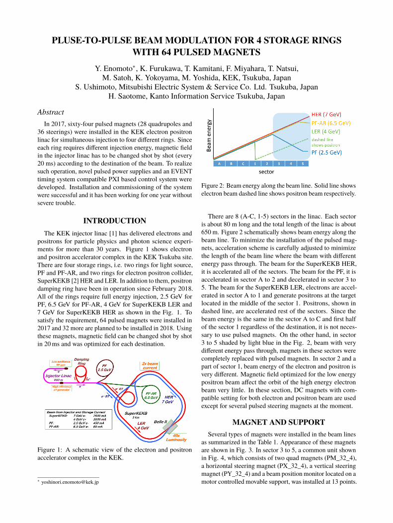
positrons for particle physics and photon science experi-ments for more than 30 years. Figure 1 shows electronand positron accelerator complex in the KEK Tsukuba site.There are four storage rings, i.e. two rings for light source,PF and PF-AR, and two rings for electron positron collider,SuperKEKB [2] HER and LER. In addition to them, positrondamping ring have been in operation since February 2018.All of the rings require full energy injection, 2.5 GeV forPF, 6.5 GeV for PF-AR, 4 GeV for SuperKEKB LER and7 GeV for SuperKEKB HER as shown in the Fig. 1. Tosatisfy the requirement, 64 pulsed magnets were installed in2017 and 32 more are planned to be installed in 2018. Usingthese magnets, magnetic field can be changed shot by shotin 20 ms and was optimized for each destination.
Figure 1: A schematic view of the electron and positronaccelerator complex in the KEK.
Figure 2: Beam energy along the beam line. Solid line showselectron beam dashed line shows positron beam respectively.
There are 8 (A-C, 1-5) sectors in the linac. Each sectoris about 80 m long and the total length of the linac is about650 m. Figure 2 schematically shows beam energy along thebeam line. To minimize the installation of the pulsed mag-nets, acceleration scheme is carefully adjusted to minimizethe length of the beam line where the beam with differentenergy pass through. The beam for the SuperKEKB HER,it is accelerated all of the sectors. The beam for the PF, it isaccelerated in sector A to 2 and decelerated in sector 3 to5. The beam for the SuperKEKB LER, electrons are accel-erated in sector A to 1 and generate positrons at the targetlocated in the middle of the sector 1. Positrons, shown indashed line, are accelerated rest of the sectors. Since thebeam energy is the same in the sector A to C and first halfof the sector 1 regardless of the destination, it is not neces-sary to use pulsed magnets. On the other hand, in sector3 to 5 shaded by light blue in the Fig. 2, beam with verydifferent energy pass through, magnets in these sectors werecompletely replaced with pulsed magnets. In sector 2 and apart of sector 1, beam energy of the electron and positron isvery different. Magnetic field optimized for the low energypositron beam affect the orbit of the high energy electronbeam very little. In these section, DC magnets with com-patible setting for both electron and positron beam are usedexcept for several pulsed steering magnets at the moment.
MAGNET AND SUPPORTSeveral types of magnets were installed in the beam lines
as summarized in the Table 1. Appearance of these magnetsare shown in Fig. 3. In sector 3 to 5, a common unit shownin Fig. 4, which consists of two quad magnets (PM_32_4),a horizontal steering magnet (PX_32_4), a vertical steeringmagnet (PY_32_4) and a beam position monitor located on amotor controlled movable support, was installed at 13 points.
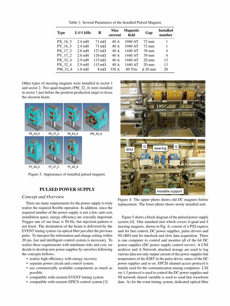
Table 1: Several Parameters of the Installed Pulsed Magnets
Type L@1 kHz R Max Magnetic Gap Installedcurrent field number
PX_16_5 2.4 mH 71 mW 40 A 1040 AT 72 mm 1PY_16_5 2.4 mH 71 mW 40 A 1040 AT 72 mm 1PX_17_2 2.6 mH 127 mW 40 A 1440 AT 39 mm 4PY_17_2 2.6 mH 126 mW 40 A 1440 AT 39 mm 4PX_32_4 2.9 mH 115 mW 40 A 1440 AT 20 mm 13PX_32_4 2.9 mH 115 mW 40 A 1440 AT 20 mm 13PM_32_4 1.0 mH 8 mW 330 A 60 T/m φ 20 mm 28
Other types of steering magnets were installed in sector 1and sector 2. Two quad magnets (PM_32_4) were installedin sector 1 just before the positron production target to focusthe electron beam.
Figure 3: Appearance of installed pulsed magnets.
PULSED POWER SUPPLYConcept and Overview
There are many requirements for the power supply to trulyrealize the required flexible operation. In addition, since therequired number of the power supply is not a few, unit cost,installation space, energy efficiency are crucially important.Trigger rate of our linac is 50 Hz, but injection pattern isnot fixed. The destination of the beam is delivered by theEVENT timing system via optical fiber just after the previouspulse. To interpret the information and change setting within20 ms, fast and intelligent control system is necessary. Torealize these requirements with minimum risks and cost, wedecide to develop new power supplies by ourselves followingthe concepts bellows.
• realize high efficiency with energy recovery• separate power circuit and control system• use commercially available components as much as
possible• compatible with existent EVENT timing system• compatible with existent EPICS control system [3]
Figure 4: The upper photo shows old DC magnets beforereplacement. The lower photo shows newly installed unit.
Figure 5 shows a block diagram of the pulsed power supplysystem [4]. One standard unit which covers 4 quad and 4steering magnets, shown in Fig. 6, consist of a PXI expressunit for fast control, DC power supplies, pulse drivers andNI cRIO unit for interlock and slow data acquisition. Thereis one computer to control and monitor all of the 64 DCpower supplies (DC power supply control server). A CSSarchiver and A Network attached storage are used to logvarious data not only output current of the power supplies buttemperature of the IGBT in the pulse driver, status of the DCpower supplies and so on. EPCIS channel access protocol ismainly used for the communication among computers. LXIver 1.3 protocol is used to control the DC power supplies andNI network shared variable is used to send fast waveformdata. As for the event timing system, dedicated optical fiber

is directly connected to the module. Most of the softwareis written by LabVIEW 2016 (32 bit) with NI DSC moduleand running on Windows 8.1.
CSS archiver
DC power supply
PXI express (fast control)
cRIO
(in
terlo
ck a
nd d
ata
logg
ing)
pules driver
NAS
LAN operator´s machine
CSS archiver
magnet
event signal
EPICS CA
DC power supplycontrol server
NI network shared variableLXI ver. 1.3
standard unit
Figure 5: Block diagram of the power supply control andmonitor system.
Figure 6: A photo of the standard unit for 4 quad and 4steering magnets.
Pulse Driver for Quad MagnetDesign parameters of the pulse driver for the Q magnet
is summarized in Table 2. To achieve these values, a novelswitching power supply with energy recovery circuit wasdeveloped
Table 2: Design Parameters of the Pulse Driver for QuadMagnet
Parameter Valuemax current 330 Amax voltage 230 Vstability 0.1%cooling water cooledpower consumption 1500 Wrepetition 50 Hz
Figure 7: A photo of the pulse driver for quad magnet.
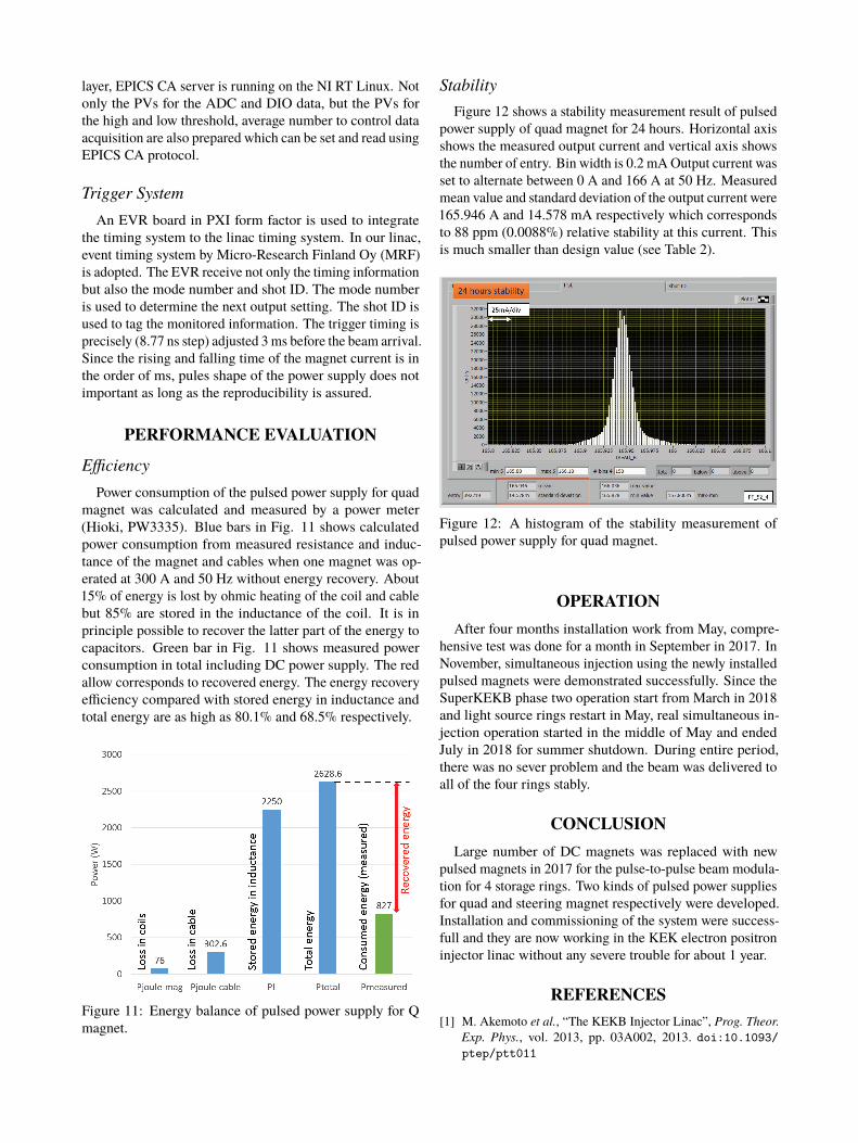
Figures 7 and 8 show an appearance and a conceptualcircuit diagram of the pulse driver respectively. The circuitconsists of two IGBTs (IGBT 1 and IGBT 2), two capacitors(C_HV and C_LV), two DC power supply (VH and VL) andseveral diodes. After the trigger signal arrives, first, bothof the IGBTs turn on and current provided from both of thecapacitors pass the load through red lines shown in the upperfigure in Fig. 8. When the current reach the set value, IGBT1 turn off and the gate voltage of the IGBT 2 is controlled tokeep constant output current. Finally, after the beam passthrough the magnet, IGBT 2 turn off. Stored energy in theload (magnet) is recovered to the capacitor (C_HV) throughthe red line shown in the bottom figure Fig. 8.
By combination of such energy recovery mechanism andwater cooling system, the outsize dimension of the pulsedriver is as small as EIA 3U in height. Output current ismonitored and fed back by two independent DCCTs withhall sensor (LEM LF 1005-S) which are calibrated by a moreprecise external DCCT (Hioki 9709).
Pulse Driver for Steering MagnetDesign parameters of the pulse driver for steering magnet
is summarized in Table 3. Compared with the driver forquad magnet, output power is very small but bipolar outputis required. To meet with this condition, power operationalamplifier (Apex PA12 [5]) was used for the key device. Al-though such kind of amplifier is low efficiency compared
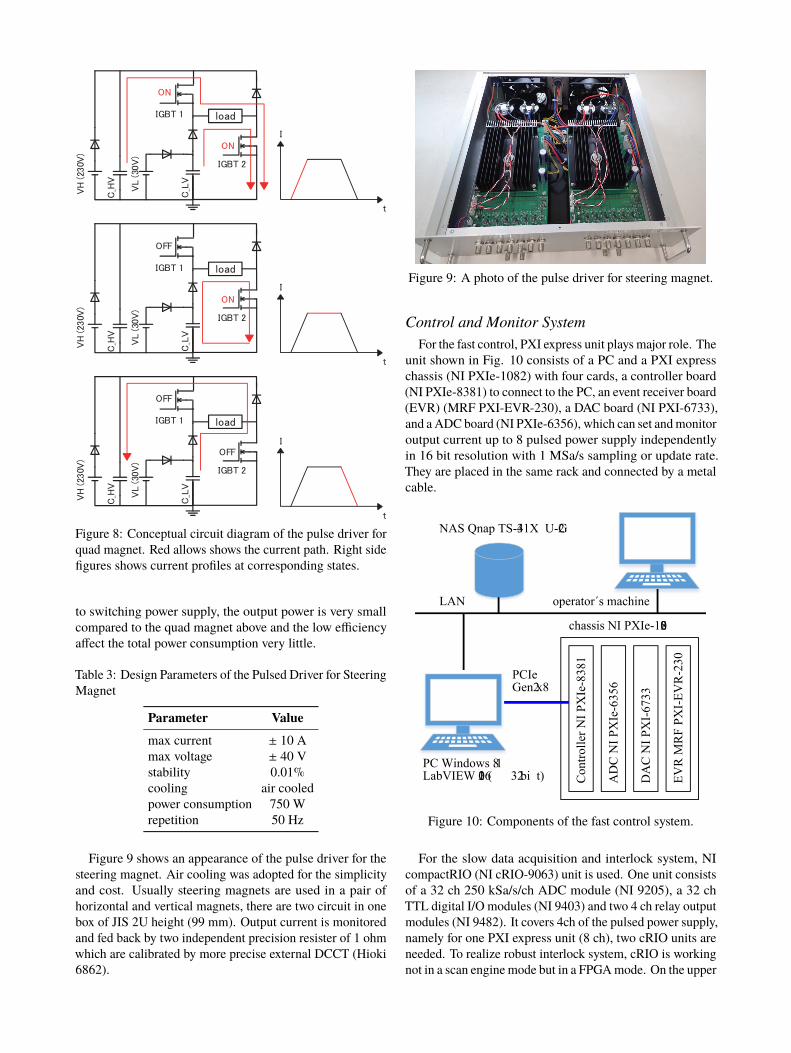
Figure 8: Conceptual circuit diagram of the pulse driver forquad magnet. Red allows shows the current path. Right sidefigures shows current profiles at corresponding states.
to switching power supply, the output power is very smallcompared to the quad magnet above and the low efficiencyaffect the total power consumption very little.
Table 3: Design Parameters of the Pulsed Driver for SteeringMagnet
Parameter Valuemax current ± 10 Amax voltage ± 40 Vstability 0.01%cooling air cooledpower consumption 750 Wrepetition 50 Hz
Figure 9 shows an appearance of the pulse driver for thesteering magnet. Air cooling was adopted for the simplicityand cost. Usually steering magnets are used in a pair ofhorizontal and vertical magnets, there are two circuit in onebox of JIS 2U height (99 mm). Output current is monitoredand fed back by two independent precision resister of 1 ohmwhich are calibrated by more precise external DCCT (Hioki6862).
Figure 9: A photo of the pulse driver for steering magnet.
Control and Monitor SystemFor the fast control, PXI express unit plays major role. The
unit shown in Fig. 10 consists of a PC and a PXI expresschassis (NI PXIe-1082) with four cards, a controller board(NI PXIe-8381) to connect to the PC, an event receiver board(EVR) (MRF PXI-EVR-230), a DAC board (NI PXI-6733),and a ADC board (NI PXIe-6356), which can set and monitoroutput current up to 8 pulsed power supply independentlyin 16 bit resolution with 1 MSa/s sampling or update rate.They are placed in the same rack and connected by a metalcable.
chassis NI PXIe- 1082
Con
trolle
r NI P
XIe
-838
1
AD
C N
I PX
Ie-6
356
DA
C N
I PX
I-67
33
EVR
MR
F PX
I-EV
R-2
30
NAS Q nap T S- 431X U - 2G
PC W indows 8.1LabV IEW 2016 ( 32 bi t)
LAN operator´s machine
PCIe G en2 x8
Figure 10: Components of the fast control system.
For the slow data acquisition and interlock system, NIcompactRIO (NI cRIO-9063) unit is used. One unit consistsof a 32 ch 250 kSa/s/ch ADC module (NI 9205), a 32 chTTL digital I/O modules (NI 9403) and two 4 ch relay outputmodules (NI 9482). It covers 4ch of the pulsed power supply,namely for one PXI express unit (8 ch), two cRIO units areneeded. To realize robust interlock system, cRIO is workingnot in a scan engine mode but in a FPGA mode. On the upper
layer, EPICS CA server is running on the NI RT Linux. Notonly the PVs for the ADC and DIO data, but the PVs forthe high and low threshold, average number to control dataacquisition are also prepared which can be set and read usingEPICS CA protocol.
Trigger SystemAn EVR board in PXI form factor is used to integrate
the timing system to the linac timing system. In our linac,event timing system by Micro-Research Finland Oy (MRF)is adopted. The EVR receive not only the timing informationbut also the mode number and shot ID. The mode numberis used to determine the next output setting. The shot ID isused to tag the monitored information. The trigger timing isprecisely (8.77 ns step) adjusted 3 ms before the beam arrival.Since the rising and falling time of the magnet current is inthe order of ms, pules shape of the power supply does notimportant as long as the reproducibility is assured.
PERFORMANCE EVALUATION
EfficiencyPower consumption of the pulsed power supply for quad
magnet was calculated and measured by a power meter(Hioki, PW3335). Blue bars in Fig. 11 shows calculatedpower consumption from measured resistance and induc-tance of the magnet and cables when one magnet was op-erated at 300 A and 50 Hz without energy recovery. About15% of energy is lost by ohmic heating of the coil and cablebut 85% are stored in the inductance of the coil. It is inprinciple possible to recover the latter part of the energy tocapacitors. Green bar in Fig. 11 shows measured powerconsumption in total including DC power supply. The redallow corresponds to recovered energy. The energy recoveryefficiency compared with stored energy in inductance andtotal energy are as high as 80.1% and 68.5% respectively.
Figure 11: Energy balance of pulsed power supply for Qmagnet.
StabilityFigure 12 shows a stability measurement result of pulsed
power supply of quad magnet for 24 hours. Horizontal axisshows the measured output current and vertical axis showsthe number of entry. Bin width is 0.2 mA Output current wasset to alternate between 0 A and 166 A at 50 Hz. Measuredmean value and standard deviation of the output current were165.946 A and 14.578 mA respectively which correspondsto 88 ppm (0.0088%) relative stability at this current. Thisis much smaller than design value (see Table 2).
Figure 12: A histogram of the stability measurement ofpulsed power supply for quad magnet.
OPERATIONAfter four months installation work from May, compre-
hensive test was done for a month in September in 2017. InNovember, simultaneous injection using the newly installedpulsed magnets were demonstrated successfully. Since theSuperKEKB phase two operation start from March in 2018and light source rings restart in May, real simultaneous in-jection operation started in the middle of May and endedJuly in 2018 for summer shutdown. During entire period,there was no sever problem and the beam was delivered toall of the four rings stably.
CONCLUSIONLarge number of DC magnets was replaced with new
pulsed magnets in 2017 for the pulse-to-pulse beam modula-tion for 4 storage rings. Two kinds of pulsed power suppliesfor quad and steering magnet respectively were developed.Installation and commissioning of the system were success-full and they are now working in the KEK electron positroninjector linac without any severe trouble for about 1 year.
REFERENCES[1] M. Akemoto et al., “The KEKB Injector Linac”, Prog. Theor.
Exp. Phys., vol. 2013, pp. 03A002, 2013. doi:10.1093/ptep/ptt011

[2] Y. Ohnishi et al., “Accelerator design at SuperKEKB”, Prog.Theor. Exp. Phys., vol. 2013, pp. 03A011, 2013. doi:10.1093/ptep/pts083
[3] A. Akiyama et al., “Accelerator Control System at KEKB andthe Linac”, Prog. Theor. Exp. Phys., vol. 2013, pp. 03A008,2013. doi:10.1093/ptep/pts081
[4] Y. Enomoto et al., “A New Pulse Magnet Control System inthe KEK Electron Positron LINAC”, in Proc. IPAC2018, Van-couver, BC, Canada, pp. 2121-2123, 2018. doi:10.18429/JACoW-IPAC2018-WEPAK014
[5] https://www.apexanalog.com/products/pa12.html