plunger lift solution - etcorp.ca · plunger lift solution optimize production of your well with a...
TRANSCRIPT

EXPERTS IN ADVANCEDTECHNOLOGY FOR THE OILFIELD
PLUNGER LIFTSOLUTIONby Extreme Telematics Corp.

www.ETCorp.ca

Table of ContentsALiEn2 ....................................................................................................... 5
ALiEn² Accessories & Replacement Parts .................................. 8
Solar Panel ............................................................................................. 10
Cyclops .................................................................................................... 11
Sasquatch................................................................................................12
Plunger Sensor Accessories ............................................................ 14
Iris Wireless Sensor Network Solution .........................................16
Iris Accessories .....................................................................................19
Vision .......................................................................................................20
Link ............................................................................................................21
1

2
Plunger Lift SolutionOptimize production of your well with a plunger lift system.
One of the most cost effective methods of removing accumulated liquids from the tubing and annulus of a high Gas/Liquid Ratio (GLR) natural gas or oil well, plunger lift has become increasingly popular throughout North America since the 1980s.
As a well ages, production naturally declines as reservoir pressure decreases, and liquid loading becomes a problem when the well’s energy is no longer sufficient to remove liquids on its own. At this point, intervention is required to keep the well producing at an economical rate.
Plunger lift has been proven to dramatically increase production, and is a low cost, low maintenance solution to liquid loading bearing very minimal environmental impact.

3
PLUNGER LIFT SYSTEMTypical system components include a controller, plunger sensor, plunger, lubricator, motor valve, and bottom hole assembly.
The controller is the “brains” of the system – It tells the motor valve when to open or close, and monitors the plunger arrival and pressure sensors. There are many controllers available in the form of standalone plunger lift controllers or remote terminal units (RTUs), each presenting their own set of features and benefits. Basic controllers serve to simply run the system while more complex controllers are able to automatically optimize production and allow for remote monitoring and control as part of a SCADA system.
The lubricator extends the wellhead to receive the plunger at surface, and contains a high impact spring to absorb the impact of the plunger as it arrives. Several different styles of lubricators are available, featuring single or dual ports and threaded or flanged connections. Lubricators made from different materials are also available to account for different types of gas being produced (sour or sweet), and adapt to environmental and safety conditions at the well site. Some lubricators feature an auto catch to allow the plunger to be held at surface after it has arrived to allow the well to flow more freely.
The motor valve is installed at the wellhead to shut in or open up the well to allow gas to flow to the sales/production line.
The bottom hole assembly is installed just above the perforations deep within the well to absorb the impact of the plunger, ensure the plunger stops above the perforations so the gas comes in below the plunger, and prevent damage to the seating nipple and tubing.
The plunger arrival sensor is a small but critical component of the plunger lift system. Its purpose is simple; to notify the controller of a plunger’s arrival at surface. A plunger velocity sensor replaces the arrival sensor to signal arrivals and record a plunger’s velocity, giving the ability to calculate kinetic energy to comply with the API 11 PL standard kinetic energy rating on a lubricator.
The plunger’s primary function is to act as an interface between gas and liquids inside the tubing or casing; carrying a column of fluid above it to the surface of a well. Plungers come in a variety of types to meet the needs of a particular well.
BENEFITS• Ability to optimize production
• Low capital investment
• Low maintenance cost
• Minimal well downtime
• No external energy required
• Reduced gas losses
• Minimal environmental impact
• Reduced paraffin and scale buildup
• Remote monitoring and control
• Stable well production
• Longer well life
4
USING PLUNGER LIFT TO ENHANCE PRODUCTIONThis form of artificial lift utilizes a natural gas well’s own energy to run a plunger up and down the wellbore. In its simplest form, a plunger cycle begins when an electronic controller located at the wellhead actuates a motor valve to shut in the well temporarily, cutting off gas flow and allowing the plunger to fall from the lubricator down the well inside the well’s tubing or casing.
The plunger falls through accumulated fluids and comes to rest on the bottom hole assembly. After a set time, when the plunger is assumed to be at bottom, the controller signals the valve to open again, and the pressure in the well below forces the plunger back up the wellbore carrying the column of fluid.
As the plunger returns to the lubricator, fluids are forced out through the sales line, or in some cases, out to a holding tank. At this point, the arrival of the plunger is detected and the controller moves into the next phase of the cycle, commonly referred to as the “afterflow” or “sales” portion of the cycle. This portion of the cycle is carried out for a period of time determined and set by the operator, after which the cycle beings again with the closing of the valve.
The goal is to minimize the amount of close time (not producing = not making money!!) and maximize afterflow time while avoiding plunger “fast trips” which are dangerous and cause damage to surface equipment. There are many system configurations available through the use of different plungers, pressure sensors, surface equipment, and time or pressure based algorithms existing in modern controllers.
Modern controllers, like the ALiEn2, contain optimization algorithms that track the plunger’s arrivals and make automatic adjustments to close and afterflow times to maximize production.

5
Peak production with minimal operator intervention.
ALiEn² EXPERTALiEn² is the most feature-rich plunger lift controller in its class. Patented optimization algorithms achieve maximum production with minimal operator intervention. Use as a simple well intermitter or in conjunction with a plunger and arrival sensor to optimize production. Protect your well by using a line pressure device to shut in on high line pressure. Log your plunger’s mileage with Plunger Tracking, and use Vent Tracking to keep tabs on vent time.
ALiEn²’s standard Modbus communication port enables remote monitoring and control, and is preconfigured to work with several popular SCADA
solutions. ALiEn² can also be configured to work with your internal SCADA system. No SCADA? ALiEn² is fully functional and accessible right on site.
ALiEn² and ALiEn² Expert come certified to the highest and most up-to-date safety standards available, providing unlimited safe installation locations. Features such as Fast Velocity, Dangerous Velocity, and a variety of configurable alarms protect your wellhead equipment and prevent accidents.
FEATURES AND BENEFITS• Class I, Zone 0 (Div 1) Certified
• -40°F to +160°F Operation
• 8+ Months** of Battery Standby
• Numeric/Navigation Interface
• Operate up to 3 Valves**
• RS-485 Modbus Communications
• Adaptive Seeking Velocity Optimization™
• Pressure Optimization
• Flexible Connector/Solenoid Locations
• Universal Mounting
• Type 4 Powder Coated Steel Enclosure
• Locking Door
6
ADAPTIVE SEEKING VELOCITY OPTIMIZATION™This patented* algorithm reduces the need for operator intervention by making automatic adjustments that are proportional to the current flow/close time.
When Adaptive Seeking Velocity Optimization™ is used with a plunger arrival sensor such as Cyclops®, ALiEn² reacts to the average velocity of the plunger, making proportionate changes to the amount of Close and Afterflow time for the well. The user specifies a Target Rise Velocity, which ALiEn² then works to achieve. For best results, use a Sasquatch® Plunger Velocity Sensor in conjunction with Adaptive Seeking Velocity Optimization™ to maximize production using real-time Surface Velocity. ALiEn² is the first plunger lift controller capable of optimizing on Surface Velocity; a standard feature in the ALiEn² Expert model, available as an upgrade for the ALiEn².
PRESSURE OPTIMIZATIONUse a combination of Line Pressure, Tubing Pressure, Casing Pressure**, and Differential Pressure** to optimize the well. ALiEn² automatically adapts to use enabled devices. Optimize on Flow Rate (AGA 3 table based) when using a Line Pressure and Differential Pressure sensor.
LOAD FACTORLoad Factor is a parameter that can be used to determine when to open a plunger lift well to rise the plunger. It is a ratio of the slug size (casing pressure – tubing pressure) to the lifting pressure (casing pressure – line pressure). It is used by a number of different control systems as a standard optimization setting and is a standard feature on the ALiEn² Expert plunger lift controller. Please note that this feature requires a pressure splitter.
ALiEn2’s intelligent and effective optimization algorithms will help you achieve maximum production.
* Patent Number US 9,297,238
7
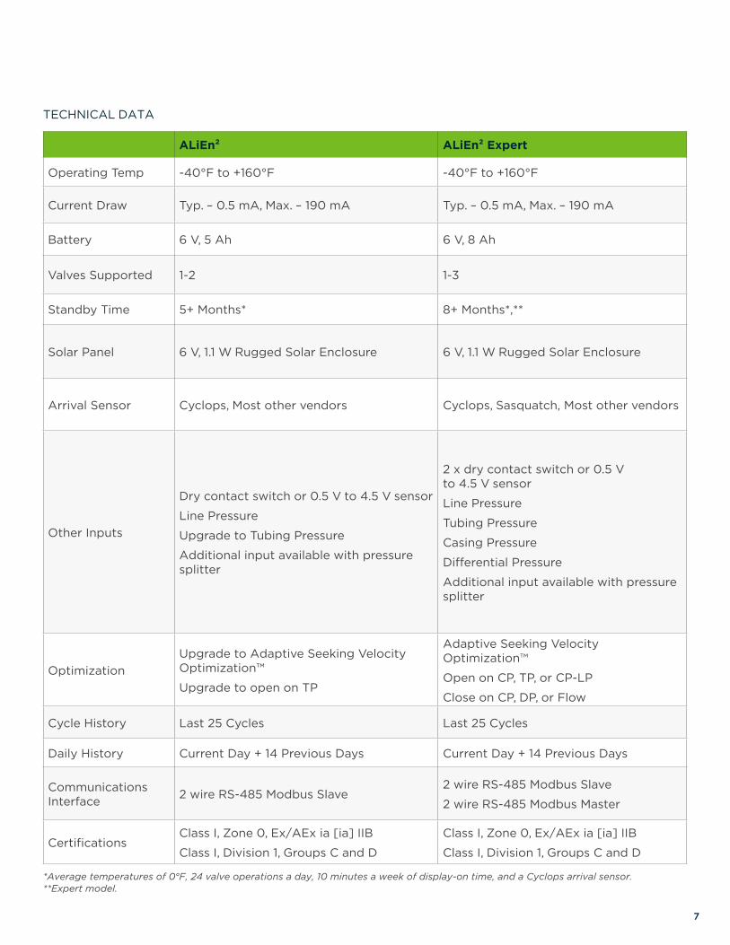
ALiEn² ALiEn² Expert
Operating Temp -40°F to +160°F -40°F to +160°F
Current Draw Typ. – 0.5 mA, Max. – 190 mA Typ. – 0.5 mA, Max. – 190 mA
Battery 6 V, 5 Ah 6 V, 8 Ah
Valves Supported 1-2 1-3
Standby Time 5+ Months* 8+ Months*,**
Solar Panel 6 V, 1.1 W Rugged Solar Enclosure 6 V, 1.1 W Rugged Solar Enclosure
Arrival Sensor Cyclops, Most other vendors Cyclops, Sasquatch, Most other vendors
Other Inputs
Dry contact switch or 0.5 V to 4.5 V sensor
Line Pressure
Upgrade to Tubing Pressure
Additional input available with pressure splitter
2 x dry contact switch or 0.5 V to 4.5 V sensor
Line Pressure
Tubing Pressure
Casing Pressure
Differential Pressure
Additional input available with pressure splitter
OptimizationUpgrade to Adaptive Seeking Velocity Optimization™
Upgrade to open on TP
Adaptive Seeking Velocity Optimization™
Open on CP, TP, or CP-LP
Close on CP, DP, or Flow
Cycle History Last 25 Cycles Last 25 Cycles
Daily History Current Day + 14 Previous Days Current Day + 14 Previous Days
Communications Interface 2 wire RS-485 Modbus Slave
2 wire RS-485 Modbus Slave
2 wire RS-485 Modbus Master
CertificationsClass I, Zone 0, Ex/AEx ia [ia] IIB
Class I, Division 1, Groups C and D
Class I, Zone 0, Ex/AEx ia [ia] IIB
Class I, Division 1, Groups C and D
*Average temperatures of 0°F, 24 valve operations a day, 10 minutes a week of display-on time, and a Cyclops arrival sensor. **Expert model.
TECHNICAL DATA

8
ALiEn² Accessories & Replacement Parts
ALiEn2 SIMULATOR
Use this free tool for testing, training, and troubleshooting. This simulator functions exactly the same as the actual product, and includes the ability to manipulate simulated well conditions including battery & solar voltage, pressure (line, casing, differential, tubing) velocity readings, and plunger arrivals.
UNIVERSAL MOUNTING BRACKET
Each ALiEn² comes with the innovative Universal Mounting Bracket. With support for wall, single vertical stud, single horizontal stud, vertical pipe, horizontal pipe, or valve mount. This is the only mounting bracket you will ever need.
UPGRADE, TEST & TROUBLESHOOT ALiEn2 WITH LINK AND VISION SOFTWARE
Link connects ETC plunger lift controllers, Cyclops plunger arrival sensors, and Sasquatch plunger velocity sensors to our Vision Device Management platform. Keep your controller loaded with the latest features using Vision Device Management Software. Product updates, documentation, testing & troubleshooting for ETC controls and sensors are available in the included resource library.
SOLAR PANEL
ETC’s Solar Panel is designed for use with both the ALiEn² and ALiEn² Expert series of controllers to provide continuous operation. Even on the cloudiest of days, this panel will provide enough power to keep the battery topped up. It comes in a rugged type 4 cast aluminum enclosure.
9
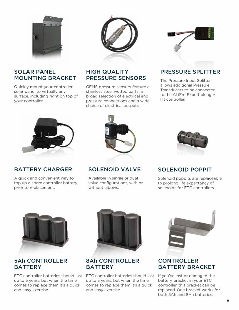
SOLAR PANEL MOUNTING BRACKET
Quickly mount your controller solar panel to virtually any surface, including right on top of your controller.
PRESSURE SPLITTER
The Pressure Input Splitter allows additional Pressure Transducers to be connected to the ALiEn² Expert plunger lift controller.
SOLENOID VALVE
Available in single or dual valve configurations, with or without elbows.
HIGH QUALITY PRESSURE SENSORS
GEMS pressure sensors feature all stainless steel wetted parts, a broad selection of electrical and pressure connections and a wide choice of electrical outputs.
BATTERY CHARGER
A quick and convenient way to top up a spare controller battery prior to replacement.
SOLENOID POPPIT
Solenoid poppits are replaceable to prolong life expectancy of solenoids for ETC controllers.
5Ah CONTROLLER BATTERY
ETC controller batteries should last up to 5 years, but when the time comes to replace them it’s a quick and easy exercise.
CONTROLLER BATTERY BRACKET
If you’ve lost or damaged the battery bracket in your ETC controller, this bracket can be replaced. One bracket works for both 5Ah and 8Ah batteries.
8Ah CONTROLLER BATTERY
ETC controller batteries should last up to 5 years, but when the time comes to replace them it’s a quick and easy exercise.

10
Solar PanelRecharge with ETC’s compact 1.1 W solar panel, which comes standard with every ALiEn² plunger lift controller.
RUGGEDETC’s solar panel comes in a rugged cast aluminum enclosure. This type 4 enclosure protects the terminal block so that it can withstand the harshest conditions and the tempered glass cover protects the solar cells, ensuring extended durability.
FLEXIBLEETC’s solar enclosure is designed with careful attention to ease of installation. Built-in mounting supports both a wall and pole mount using a standard U-bolt between 2” – 3 1/4”. ETC’s solar panel mounting bracket allows for more mounting options, including right on top of your controller. The two-part design allows the base to be mounted prior to terminating the wiring, and the enclosure lid containing the electronics fastens securely with captive screws. The pre-drilled 1/2” NPT port enables the use of armoured cabling with a Teck connector or instrumentation cabling with a standard cable gland.
OPERATIONThis panel is designed for use with both the ALiEn² and ALiEn² Expert series of controllers to provide continuous operation. Even on the cloudiest of days, this panel will provide enough power to keep the battery topped up.
TECHNICAL DATA
Peak Power 1.1 W
Open Circuit Voltage 9.76 V
Max Power Voltage 8.16 V
Short Circuit Current 149 mA
Max Power Current 135 mA
CertificationsClass I, Div 2, Groups A, B, C, & D, Temperature Code: T3C
Enclosure Type 4 Cast Aluminum

11
TECHNICAL DATA
MISSED ARRIVAL? FALSE DETECTS? NOT ON MY WATCH.Cyclops is not your average plunger arrival sensor. Utilizing modern Geomagnetic Sensing Technology™, market-leading Cyclops is the most advanced and reliable sensor available.
Within the rugged enclosure lies a geomagnetic “eye” and a tiny yet powerful microprocessor. When powered, Cyclops is actively watching for a change in the earth’s magnetic field around it to signal plunger arrival. Constantly filtering out “background noise” from nearby equipment or environmental changes, Cyclops is able to consistently detect any type of plunger as it arrives at surface.
ETC’s innovative line of plunger sensors provide advantages that no other plunger sensors offer, such as the ability to adjust sensitivity, upgrade software, or troubleshoot problematic wells right at the well head.
FEATURES AND BENEFITS• Digitally Controlled Output
• Intrinsically Safe or Explosion Proof
• Wireless Solution Available
• -40°F to +160°F Operation
• 5 V to 24 V Operating Voltage
• Low Power
• Adjustable Sensitivity
• Self Calibrating
• 1/2” NPT Port
Supply Voltage 5 V – 24 V DC
Current Draw Typ. – 0.77 mA, Max. – 0.80 mA
Switch Interface Dry contact, normally open, 100 Ω impedance
Communications Interface 1 wire RS-485 test interface
Operating Temperature -40°F to +160°F
Certification (IS Model)
Class I, Zone 0, AEx ia IIB T4
Class I, Division 1, Groups C, D T4; Ex ia IIB T4
Class I, Zone 2, Group IIC T4
Class I, Division 2, Groups A, B, C, D T4
Certification (ATX Model) CE Ex II 3G Ex nA IIC T4 Gc
Certification (ExP Model)Class I, Zone 1, AEx d IIB T4
Class I, Division 1, Groups C, D; Ex d IIB T4
Utilizing modern Geomagnetic Sensing Technology™, Cyclops is the most advanced and reliable plunger sensor available.

12
Sasquatch is the next stage in the evolution of plunger detection. The unique design of Sasquatch is based on the proven technology behind the Cyclops® plunger arrival sensor.
Repetitive fast plungers are a common problem in plunger lift causing costly damage to equipment and production downtime. A lubricator breach can lead to incident reports, spills and injuries. Hoping to avoid these issues, producers replace lubricator springs and plungers on a regular basis. In many cases, perfectly good equipment is being prematurely discarded, leading to wasted labor and equipment costs. Sasquatch gives you the power to reduce or even prevent these occurrences and prolongs the life of wellhead equipment by enabling detection of fast plungers long before they cause problems.
Sasquatch is the first and only sensor of its kind, based on the proven Geomatic Sensing Technology™ behind the Cyclops arrival sensor, and boasts many of the same features and benefits. It not only detects the arrival of the plunger, but also measures and stores the instantaneous surface velocity of the plunger.
Sasquatch uses the surface velocity and mass of the plunger to calculate the kinetic energy of each plunger arrival in real time.
13
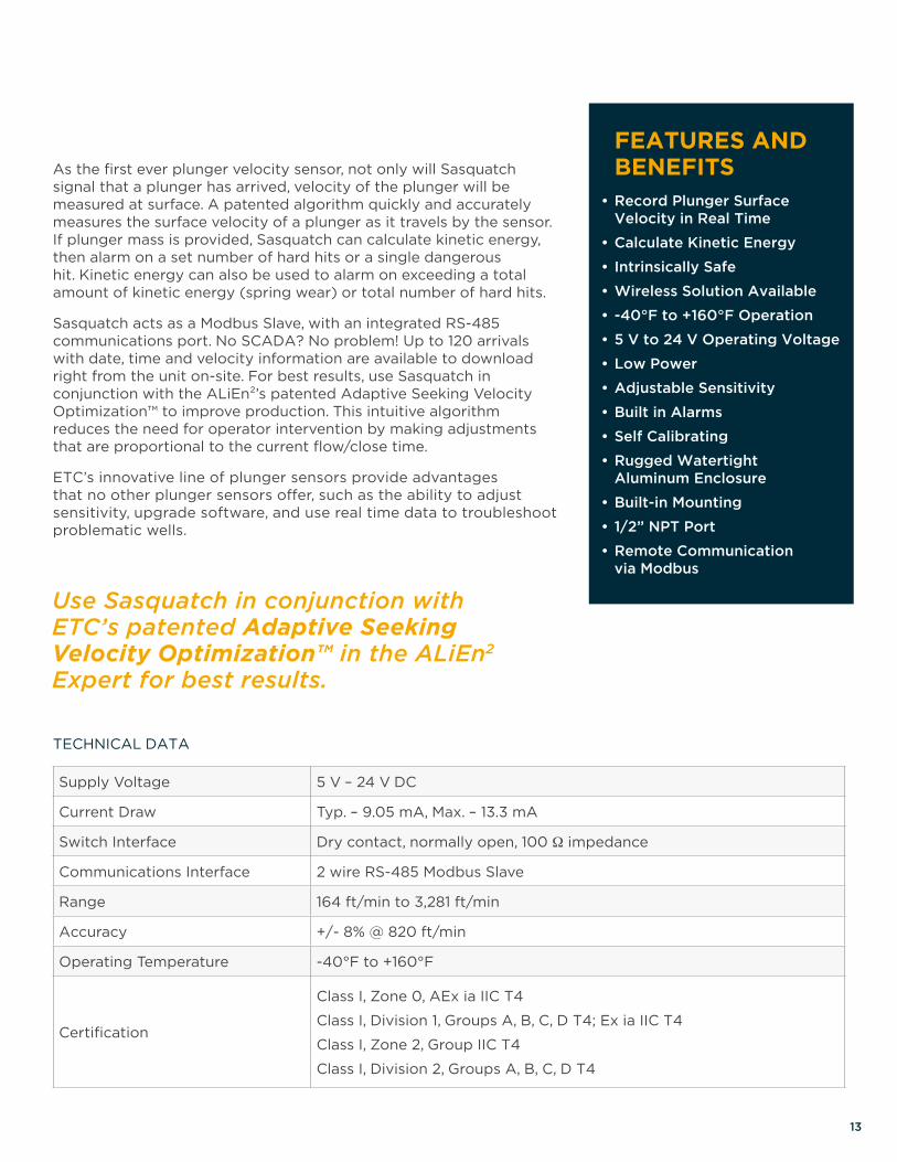
TECHNICAL DATA
Supply Voltage 5 V – 24 V DC
Current Draw Typ. – 9.05 mA, Max. – 13.3 mA
Switch Interface Dry contact, normally open, 100 Ω impedance
Communications Interface 2 wire RS-485 Modbus Slave
Range 164 ft/min to 3,281 ft/min
Accuracy +/- 8% @ 820 ft/min
Operating Temperature -40°F to +160°F
Certification
Class I, Zone 0, AEx ia IIC T4
Class I, Division 1, Groups A, B, C, D T4; Ex ia IIC T4
Class I, Zone 2, Group IIC T4
Class I, Division 2, Groups A, B, C, D T4
FEATURES AND BENEFITS• Record Plunger Surface Velocity in Real Time
• Calculate Kinetic Energy
• Intrinsically Safe
• Wireless Solution Available
• -40°F to +160°F Operation
• 5 V to 24 V Operating Voltage
• Low Power
• Adjustable Sensitivity
• Built in Alarms
• Self Calibrating
• Rugged Watertight Aluminum Enclosure
• Built-in Mounting
• 1/2” NPT Port
• Remote Communication via Modbus
As the first ever plunger velocity sensor, not only will Sasquatch signal that a plunger has arrived, velocity of the plunger will be measured at surface. A patented algorithm quickly and accurately measures the surface velocity of a plunger as it travels by the sensor. If plunger mass is provided, Sasquatch can calculate kinetic energy, then alarm on a set number of hard hits or a single dangerous hit. Kinetic energy can also be used to alarm on exceeding a total amount of kinetic energy (spring wear) or total number of hard hits.
Sasquatch acts as a Modbus Slave, with an integrated RS-485 communications port. No SCADA? No problem! Up to 120 arrivals with date, time and velocity information are available to download right from the unit on-site. For best results, use Sasquatch in conjunction with the ALiEn²’s patented Adaptive Seeking Velocity Optimization™ to improve production. This intuitive algorithm reduces the need for operator intervention by making adjustments that are proportional to the current flow/close time.
ETC’s innovative line of plunger sensors provide advantages that no other plunger sensors offer, such as the ability to adjust sensitivity, upgrade software, and use real time data to troubleshoot problematic wells.
Use Sasquatch in conjunction with ETC’s patented Adaptive Seeking Velocity Optimization™ in the ALiEn2 Expert for best results.

14
Plunger Sensor Accessories
PLUNGER SENSOR WIRING KIT
Includes a 3’ length of cable and ½” NPT connector to connect Cyclops to a plunger sensor node.
WIRELESS SOLAR NODE FOR SASQUATCH
An internal rechargeable battery pack with integrated high efficiency solar charger is available to power Sasquatch in areas where a power source is not readily available. Gateway, mounting bracket, programming cable, and wiring kit sold separately. See Iris page for more info.
WIRELESS NODE FOR CYCLOPS
The Iris Wireless Bridge provides the ability to use Cyclops plunger arrival sensors in areas where wire is not an economically viable or easily attainable option. Gateway, plunger sensor node, mounting bracket, programming cable, and wiring kit sold separately. See Iris page for more info.
SURFACE VELOCITY DIAGNOSTIC KIT
The Surface Velocity Diagnostic Kit helps operators know and understand how the impact (kinetic energy) of a plunger at surface affects surface equipment. Consisting of ETC’s Link, Vision and Sasquatch products, the Surface Velocity Diagnostic Kit can be used both on-site and remotely to measure and record plunger speed on every arrival.
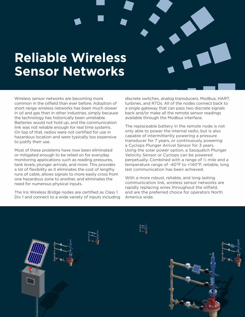
Reliable Wireless Sensor Networks
Wireless sensor networks are becoming more common in the oilfield than ever before. Adoption of short range wireless networks has been much slower in oil and gas than in other industries, simply because the technology has historically been unreliable. Batteries would not hold up, and the communication link was not reliable enough for real time systems. On top of that, radios were not certified for use in hazardous location and were typically too expensive to justify their use.
Most of these problems have now been eliminated or mitigated enough to be relied on for everyday monitoring applications such as reading pressures, tank levels, plunger arrivals, and more. This provides a lot of flexibility as it eliminates the cost of lengthy runs of cable, allows signals to more easily cross from one hazardous zone to another, and eliminates the need for numerous physical inputs.
The Iris Wireless Bridge nodes are certified as Class 1 Div 1 and connect to a wide variety of inputs including
discrete switches, analog transducers, Modbus, HART, turbines, and RTDs. All of the nodes connect back to a single gateway that can pass two discrete signals back and/or make all the remote sensor readings available through the Modbus interface.
The replaceable battery in the remote node is not only able to power the internal radio, but is also capable of intermittently powering a pressure transducer for 7 years, or continuously powering a Cyclops Plunger Arrival Sensor for 3 years. Using the solar power option, a Sasquatch Plunger Velocity Sensor or Cyclops can be powered perpetually. Combined with a range of ½ mile and a temperature range of -40°F to +140°F, reliable, long last communication has been achieved.
With a more robust, reliable, and long lasting communication link, wireless sensor networks are rapidly replacing wires throughout the oilfield, and are the preferred choice for operators North America wide.
16
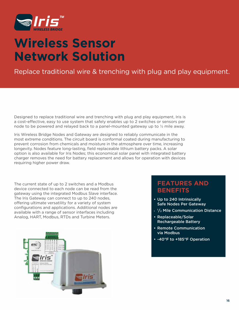
Designed to replace traditional wire and trenching with plug and play equipment, Iris is a cost-effective, easy to use system that safely enables up to 2 switches or sensors per node to be powered and relayed back to a panel-mounted gateway up to ½ mile away.
Iris Wireless Bridge Nodes and Gateway are designed to reliably communicate in the most extreme conditions. The circuit board is conformal coated during manufacturing to prevent corrosion from chemicals and moisture in the atmosphere over time, increasing longevity. Nodes feature long-lasting, field replaceable lithium battery packs. A solar option is also available for Iris Nodes; this economical solar panel with integrated battery charger removes the need for battery replacement and allows for operation with devices requiring higher power draw.
The current state of up to 2 switches and a Modbus device connected to each node can be read from the gateway using the integrated Modbus Slave interface. The Iris Gateway can connect to up to 240 nodes, offering ultimate versatility for a variety of system configurations and applications. Additional nodes are available with a range of sensor interfaces including Analog, HART, Modbus, RTDs and Turbine Meters.
FEATURES AND BENEFITS• Up to 240 Intrinsically Safe Nodes Per Gateway
• 1/2 Mile Communication Distance
• Replaceable/Solar Rechargeable Battery
• Remote Communication via Modbus
• -40°F to +185°F Operation
Wireless Sensor Network SolutionReplace traditional wire & trenching with plug and play equipment.
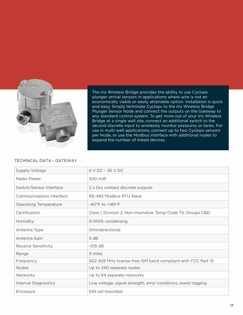
Supply Voltage 6 V DC – 36 V DC
Radio Power 500 mW
Switch/Sensor Interface 2 x Dry contact discrete outputs
Communications Interface RS-485 Modbus RTU Slave
Operating Temperature -40°F to +185°F
Certification Class I, Division 2, Non-incendive, Temp Code T5, Groups C&D
Humidity 0-100% condensing
Antenna Type Omnidirectional
Antenna Gain 5 dB
Receive Sensitivity -105 dB
Range 3 miles
Frequency 902-928 MHz license-free ISM band compliant with FCC Part 15
Nodes Up to 240 separate nodes
Networks Up to 64 separate networks
Internal Diagnostics Line voltage, signal strength, error conditions, event logging
Enclosure DIN rail mounted
17
TECHNICAL DATA - GATEWAY
The Iris Wireless Bridge provides the ability to use Cyclops plunger arrival sensors in applications where wire is not an economically viable or easily attainable option. Installation is quick and easy; Simply terminate Cyclops to the Iris Wireless Bridge Plunger Sensor Node and connect the outputs on the Gateway to any standard control system. To get more out of your Iris Wireless Bridge at a single well site, connect an additional switch to the second discrete input to wirelessly monitor pressures or tanks. For use in multi-well applications, connect up to two Cyclops sensors per Node, or use the Modbus interface with additional nodes to expand the number of linked devices.
18
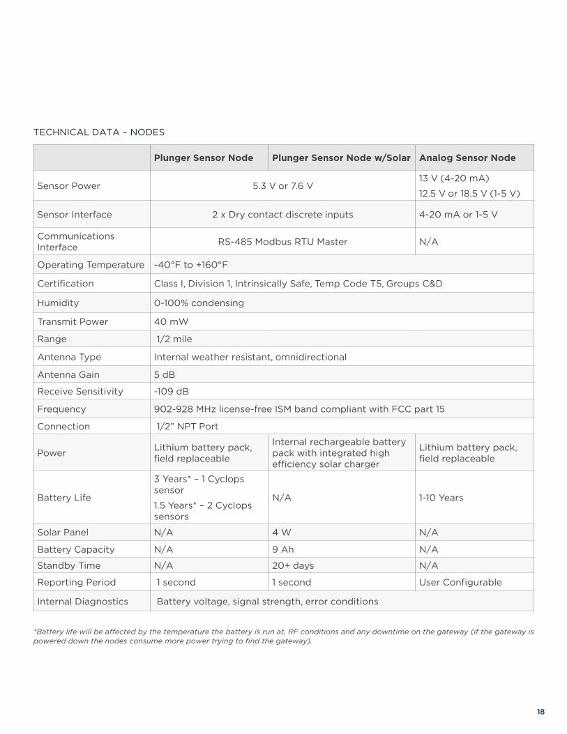
TECHNICAL DATA – NODES
Plunger Sensor Node Plunger Sensor Node w/Solar Analog Sensor Node
Sensor Power 5.3 V or 7.6 V13 V (4-20 mA)
12.5 V or 18.5 V (1-5 V)
Sensor Interface 2 x Dry contact discrete inputs 4-20 mA or 1-5 V
Communications Interface RS-485 Modbus RTU Master N/A
Operating Temperature -40°F to +160°F
Certification Class I, Division 1, Intrinsically Safe, Temp Code T5, Groups C&D
Humidity 0-100% condensing
Transmit Power 40 mW
Range 1/2 mile
Antenna Type Internal weather resistant, omnidirectional
Antenna Gain 5 dB
Receive Sensitivity -109 dB
Frequency 902-928 MHz license-free ISM band compliant with FCC part 15
Connection 1/2” NPT Port
Power Lithium battery pack, field replaceable
Internal rechargeable battery pack with integrated high efficiency solar charger
Lithium battery pack, field replaceable
Battery Life
3 Years* – 1 Cyclops sensor
1.5 Years* – 2 Cyclops sensors
N/A 1-10 Years
Solar Panel N/A 4 W N/A
Battery Capacity N/A 9 Ah N/A
Standby Time N/A 20+ days N/A
Reporting Period 1 second 1 second User Configurable
Internal Diagnostics Battery voltage, signal strength, error conditions
*Battery life will be affected by the temperature the battery is run at, RF conditions and any downtime on the gateway (if the gateway is powered down the nodes consume more power trying to find the gateway).
19
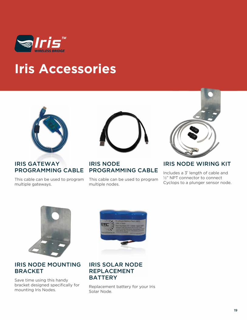
Iris Accessories
IRIS GATEWAY PROGRAMMING CABLE
This cable can be used to program multiple gateways.
IRIS NODE MOUNTING BRACKET
Save time using this handy bracket designed specifically for mounting Iris Nodes.
IRIS SOLAR NODE REPLACEMENT BATTERY
Replacement battery for your Iris Solar Node.
IRIS NODE PROGRAMMING CABLE
This cable can be used to program multiple nodes.
IRIS NODE WIRING KIT
Includes a 3’ length of cable and ½” NPT connector to connect Cyclops to a plunger sensor node.

Product updates, documentation, testing & troubleshooting for ETC controls and sensors.
20
Vision Device Management is a free PC-based tool used with Link™ to configure, test, and troubleshoot ETC controls, sensors, and wireless products, and download & install firmware updates. When used in conjunction with the Sasquatch Plunger Velocity Sensor, Vision and Link become the industry’s first Plunger Velocity Diagnostic Kit. This kit helps operators understand how the impact (kinetic energy) of a plunger at surface affects surface equipment.
Vision also includes ETC’s full resource library; including application notes, certification documents, manuals, and other supporting documents and tools for our products.
USE VISION TO:• Upgrade and verify software on: ALiEn2
(and other custom branded) plunger lift and chemical injection controllers, Cyclops, and Sasquatch
• Adjust sensitivity (beyond 7 setting external dial) on Cyclops and Sasquatch
• Monitor plunger arrivals using Cyclops and Sasquatch
• Determine velocity/kinetic energy of a plunger with Sasquatch
• View arrival information stored on Sasquatch
• Set/Get Sasquatch settings via Modbus
• Configure Iris Wireless Bridge gateway and node
• Access ETC’s resource library
With Vision Device Management, the latest firmware for ETC controls and sensors is always at your fingertips. To ensure producers have access to the most modern features & the best optimization algorithms, ETC occasionally releases new firmware versions for controllers like the ALiEn² plunger lift controller and the PC180 Chemical Injection controller. Vision also allows users to safely ‘see what Cyclops or Sasquatch sees’ as a plunger arrives in the lubricator, which can help users determine the cause of false detects or missed arrivals on a problem well.
Upgrading software on any ETC product is simple and quick with Vision. As new versions are released, the latest software is automatically downloaded right to your PC when the utility opens.
Vision is currently compatible with the following ETC products:
• ALiEn2 • Sasquatch • Iris
• Cyclops
21
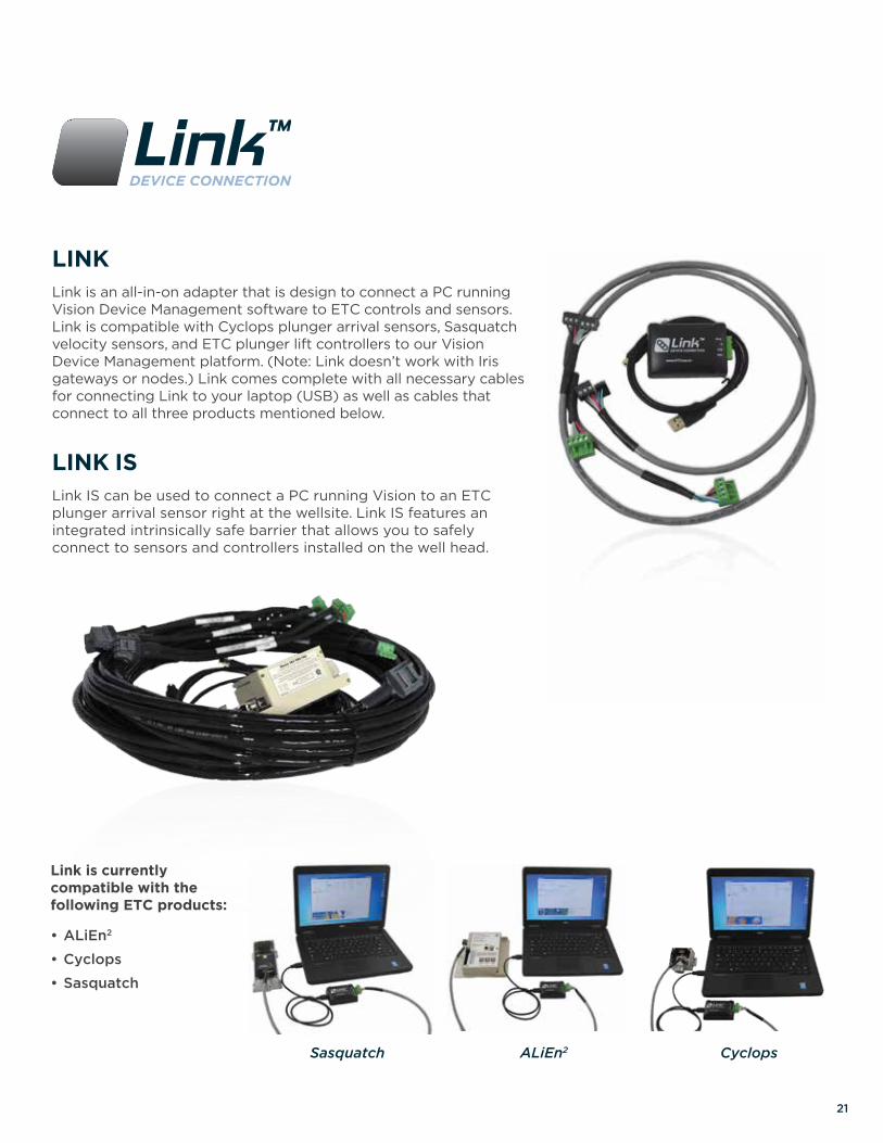
Sasquatch ALiEn2 Cyclops
Link is currently compatible with the following ETC products:
• ALiEn2
• Cyclops
• Sasquatch
LINKLink is an all-in-on adapter that is design to connect a PC running Vision Device Management software to ETC controls and sensors. Link is compatible with Cyclops plunger arrival sensors, Sasquatch velocity sensors, and ETC plunger lift controllers to our Vision Device Management platform. (Note: Link doesn’t work with Iris gateways or nodes.) Link comes complete with all necessary cables for connecting Link to your laptop (USB) as well as cables that connect to all three products mentioned below.
LINK ISLink IS can be used to connect a PC running Vision to an ETC plunger arrival sensor right at the wellsite. Link IS features an integrated intrinsically safe barrier that allows you to safely connect to sensors and controllers installed on the well head.

www.ETCorp.ca