plena all-in-one system - bosch security...
TRANSCRIPT
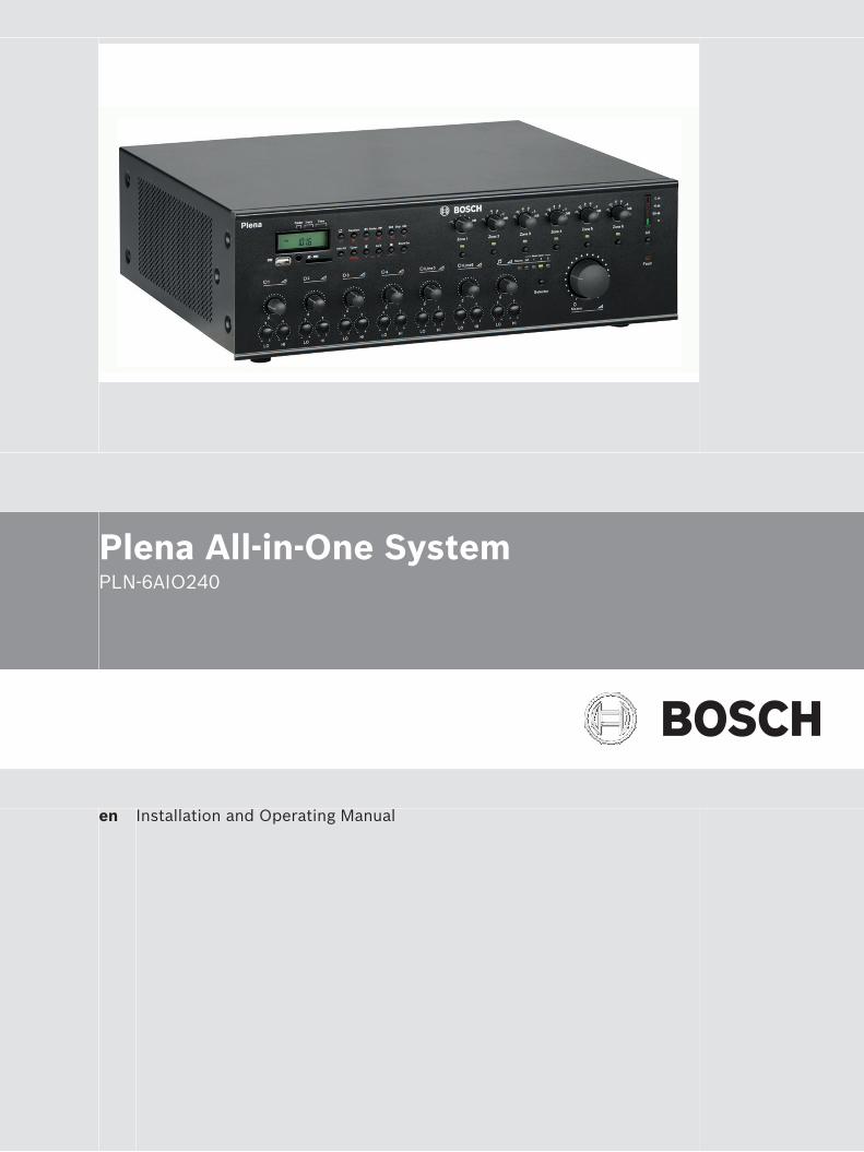
Plena All-in-One SystemPLN-6AIO240
en Installation and Operating Manual

Table of contents
1 Safety 52 About this manual 62.1 Manual purpose 62.2 Digital document 62.3 Intended audience 62.4 Alerts and notice signs 62.5 Conversion tables 72.6 Copyright and disclaimer 72.7 Document history 7
3 System Overview 83.1 Plena 83.2 Plena All-in-One System 9
4 Packaging and transportation 114.1 Unpacking 114.2 Delivered with products 11
5 Installation 125.1 Install All-in-One Unit in 19“ rack (optional) 125.2 Install Call Station 125.3 Install Wall Panel 13
6 Connection 146.1 All‑in‑One Unit connections 146.2 Microphone Adaptor connections 176.3 Call Station connections 186.4 Wall Panel connections 20
7 Configuration 217.1 All-in-One Unit configuration 217.1.1 Priority switches 237.1.2 Chime switches 237.2 Call Station hardware configuration 247.3 Call Station software configuration 257.3.1 Call station ID 257.3.2 Microphone sensitivity 267.3.3 Speech filter 267.3.4 Priority mode 267.3.5 Chime selection 277.3.6 Zone group creation 277.4 Wall Panel configuration 28
8 Operation 298.1 All-in-One Unit operation 298.2 Internal music unit 328.2.1 USB/SD/TUNER display 338.2.2 USB connector 338.2.3 IR remote control sensor 338.2.4 SD card slot 348.2.5 Music player 348.2.6 Remote control button functions 378.3 Call Station operation 38
Plena All-in-One System Table of Contents | en 3
Bosch Security Systems B.V. Installation and Operating Manual 2014.09 | V1.2 |
8.4 Wall Panel operation 40
9 Troubleshooting 429.1 Customer service 43
10 Maintenance 4411 Technical Data 4511.1 All-in-One unit 4511.2 Call Station 4911.3 Wall Panel 5011.4 Safety compliance 50
4 en | Table of Contents Plena All-in-One System
2014.09 | V1.2 | Installation and Operating Manual Bosch Security Systems B.V.
SafetyPrior to installing or operating products, always read the Important Safety Instructions whichare available as a separate multilingual document: Important Safety Instructions (Safety_ML).These instructions are supplied together with all equipment that can be connected to themains supply.
Safety precautionsThe Plena All-in-One System is designed to be connected to the public distribution network.– To avoid any risk of electric shock, all interventions must be carried out with
disconnected mains supply.– The ventilation should not be impeded by covering the ventilation openings.– Connection of external wiring to this equipment requires installation by qualified
personnel only.– The operation must only be performed by qualified personnel.– Use the apparatus in a moderate climate.
!
Caution!
These service instructions are for use by qualified service personnel only.
To reduce the risk of electric shock, do not perform any servicing other than that contained in
the operating instructions unless you are qualified to do so.
Old electrical and electronic appliancesElectrical or electronic devices that are no longer serviceable must be collected separately andsent for environmentally compatible recycling (in accordance with the European WasteElectrical and Electronic Equipment Directive).To dispose of old electrical or electronic devices, you should use the return and collectionsystems put in place in the country concerned.
1
Plena All-in-One System Safety | en 5
Bosch Security Systems B.V. Installation and Operating Manual 2014.09 | V1.2 |
About this manual
Manual purposeThe purpose of this manual is to provide information required for installing, configuring,operating and maintaining the Plena All‑In‑One System.
Digital documentThis manual is available as a digital document in the Adobe Portable Document Format (PDF).Refer to the product related information at: www.boschsecurity.com.
Intended audienceThis manual is intended for installers, operators and users of a Plena system.
Alerts and notice signsFour types of signs can be used in this manual. The type is closely related to the effect thatmay be caused if it is not observed. These signs - from least severe effect to most severeeffect - are:
Notice!
Containing additional information. Usually, not observing a ‘notice’ does not result in damage
to the equipment or personal injuries.
!
Caution!
The equipment or the property can be damaged, or persons can be lightly injured if the alert
is not observed.
!Warning!
The equipment or the property can be seriously damaged, or persons can be severely injured
if the alert is not observed.
Danger!
Not observing the alert can lead to severe injuries or death.
2
2.1
2.2
2.3
2.4
6 en | About this manual Plena All-in-One System
2014.09 | V1.2 | Installation and Operating Manual Bosch Security Systems B.V.
Conversion tablesIn this manual, SI units are used to express lengths, masses, temperatures etc. These can beconverted to non-metric units using the information provided below.
1 in = 25.4 mm 1 mm = 0.03937 in
1 in = 2.54 cm 1 cm = 0.3937 in
1 ft = 0.3048 m 1 m = 3.281 ft
1 mi = 1.609 km 1 km = 0.622 mi
Table 2.1: Conversion of units of length
1 lb = 0.4536 kg 1 kg = 2.2046 lb
Table 2.2: Conversion of units of mass
1 psi = 68.95 hPa 1 hPa = 0.0145 psi
Table 2.3: Conversion of units of pressure
Notice!
1 hPa = 1 mbar
°F = _ . °C + 32
95
°C = _ . (°F - 32)
59
Copyright and disclaimerAll rights reserved. No part of this document may be reproduced or transmitted in any form byany means, electronic, mechanical, photocopying, recording, or otherwise, without the priorwritten permission of the publisher. For information on getting permission for reprints andexcerpts, contact Bosch Security Systems B.V..The content and illustrations are subject to change without prior notice.
Document history
Release date Documentation version Reason
2014.08.14 V1.0 First edition.
2014.08.18 V1.1 Section 1: WEEE added.
2014.09.03 V1.2 Sections 5.3, 11.3, and 11.4modified.
2.5
2.6
2.7
Plena All-in-One System About this manual | en 7
Bosch Security Systems B.V. Installation and Operating Manual 2014.09 | V1.2 |
System Overview
PlenaThe Plena All-in-One System is part of the Plena product range. The Plena product rangeprovides public address solutions for places where people gather to work, worship, trade, orto relax. It is a family of system elements that are combined to create public address systemstailored for virtually any application. The Plena product range includes:– Mixers– Pre‑amplifiers– Power amplifiers– Music source unit– Digital message manager– Feedback suppressor– Call stations– "All-In-One" system– Voice Alarm System– Timer– Charger– Loop amplifierThe various elements are designed to complement each other using matched acoustical,electrical and mechanical specifications.
3
3.1
8 en | System Overview Plena All-in-One System
2014.09 | V1.2 | Installation and Operating Manual Bosch Security Systems B.V.
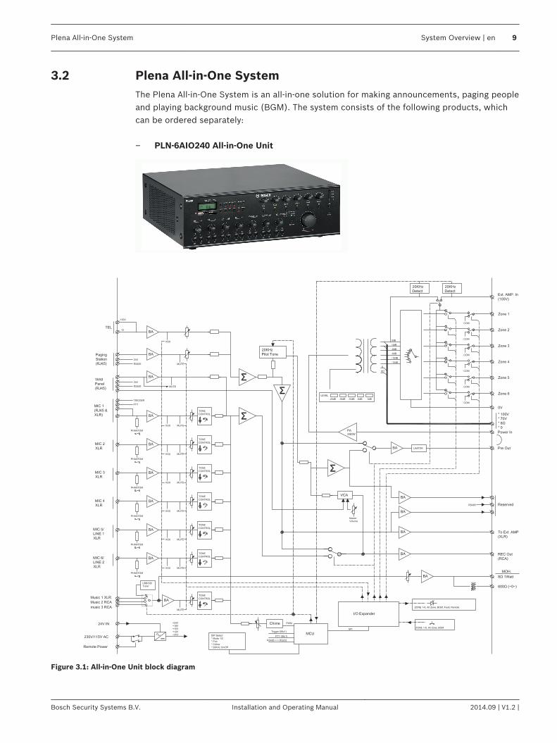
Plena All-in-One SystemThe Plena All‑in‑One System is an all‑in‑one solution for making announcements, paging peopleand playing background music (BGM). The system consists of the following products, whichcan be ordered separately: – PLN‑6AIO240 All‑in‑One Unit
Figure 3.1: All‑in‑One Unit block diagram
3.2
Plena All-in-One System System Overview | en 9
Bosch Security Systems B.V. Installation and Operating Manual 2014.09 | V1.2 |
The All‑in‑One Unit is the main product of the All‑in‑One System and integrates the followingcomponents:– a 240 W mono mixer amplifier.– SD and USB player that can play MP3 encoded files from SD and USB devices.– a digitally controlled AM/FM-tuner for receiving radio stations.Up to six microphones and three auxiliary source signals can be connected to the mixeramplifier and mixed, with priority or VOX switching. The output signal can be routed to sixdifferent zones with individual attenuation control. The unit can be extended with anadditional power amplifier, e.g. LBB1935/20, as a spare amplifier or for 2‑channel operation. – PLN‑6CS Call Station
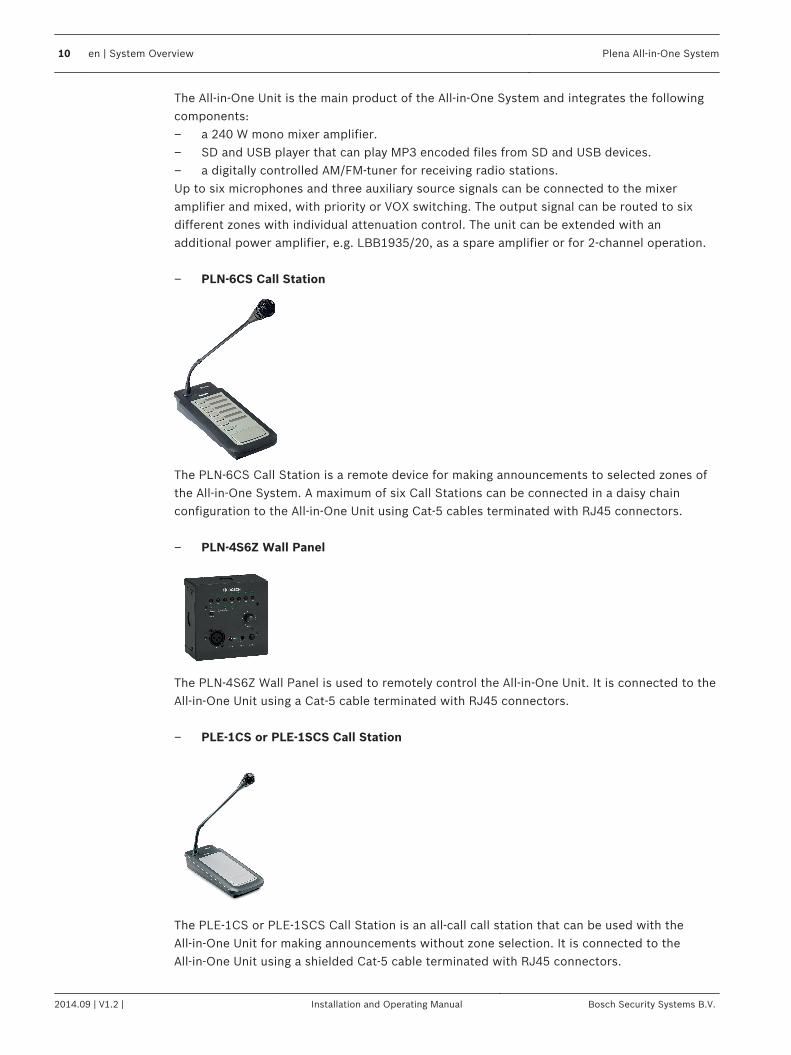
The PLN‑6CS Call Station is a remote device for making announcements to selected zones ofthe All‑in‑One System. A maximum of six Call Stations can be connected in a daisy chainconfiguration to the All‑in‑One Unit using Cat‑5 cables terminated with RJ45 connectors. – PLN‑4S6Z Wall Panel
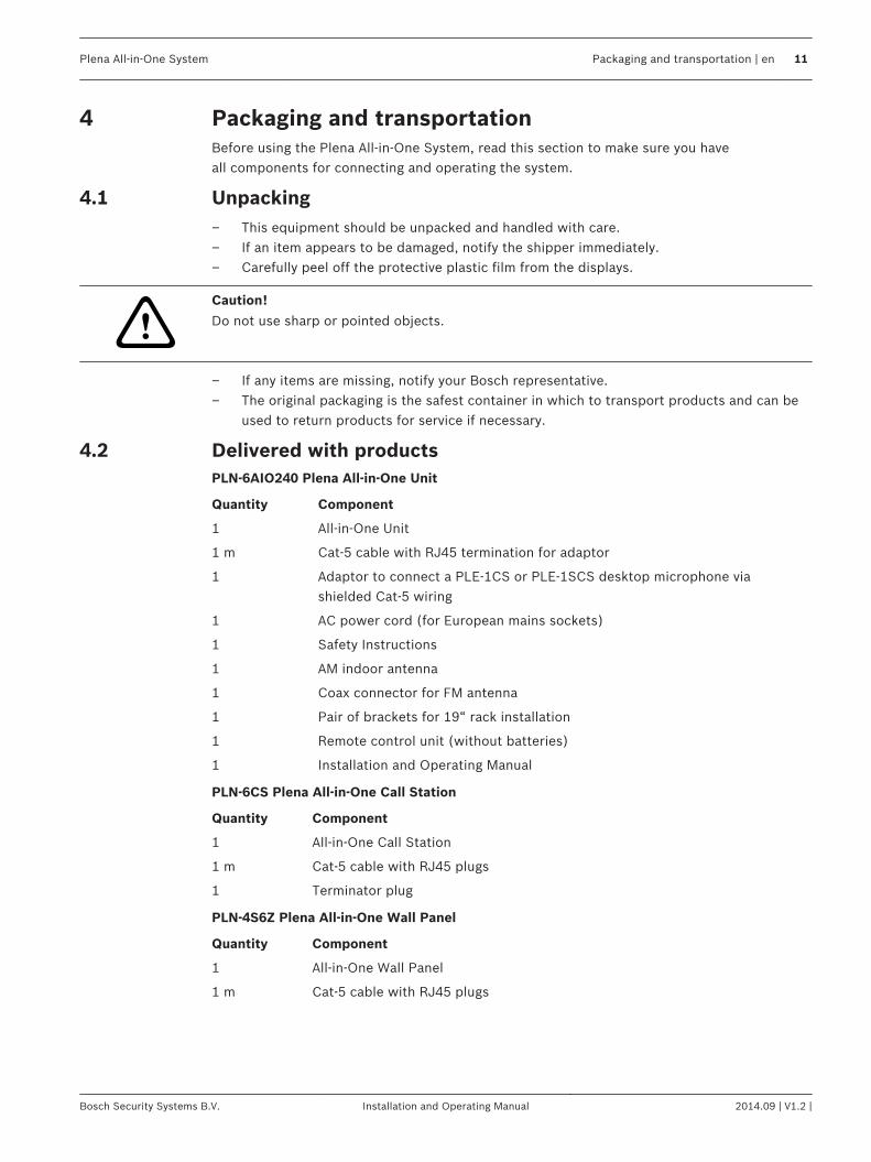
The PLN‑4S6Z Wall Panel is used to remotely control the All‑in‑One Unit. It is connected to theAll‑in‑One Unit using a Cat‑5 cable terminated with RJ45 connectors. – PLE‑1CS or PLE‑1SCS Call Station
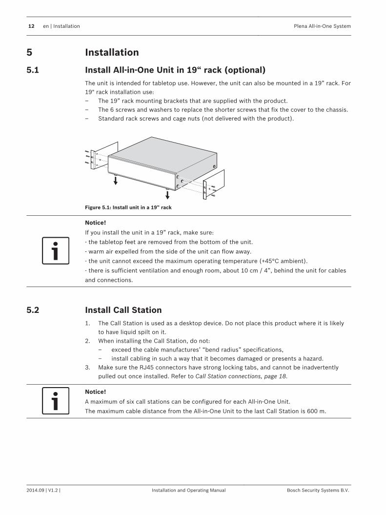
The PLE‑1CS or PLE‑1SCS Call Station is an all‑call call station that can be used with theAll‑in‑One Unit for making announcements without zone selection. It is connected to theAll‑in‑One Unit using a shielded Cat‑5 cable terminated with RJ45 connectors.
10 en | System Overview Plena All-in-One System
2014.09 | V1.2 | Installation and Operating Manual Bosch Security Systems B.V.
Packaging and transportationBefore using the Plena All‑in‑One System, read this section to make sure you haveall components for connecting and operating the system.
Unpacking– This equipment should be unpacked and handled with care.– If an item appears to be damaged, notify the shipper immediately.– Carefully peel off the protective plastic film from the displays.
!
Caution!
Do not use sharp or pointed objects.
– If any items are missing, notify your Bosch representative.– The original packaging is the safest container in which to transport products and can be
used to return products for service if necessary.
Delivered with productsPLN‑6AIO240 Plena All-in-One Unit
Quantity Component
1 All‑in‑One Unit
1 m Cat‑5 cable with RJ45 termination for adaptor
1 Adaptor to connect a PLE‑1CS or PLE‑1SCS desktop microphone viashielded Cat‑5 wiring
1 AC power cord (for European mains sockets)
1 Safety Instructions
1 AM indoor antenna
1 Coax connector for FM antenna
1 Pair of brackets for 19“ rack installation
1 Remote control unit (without batteries)
1 Installation and Operating Manual
PLN‑6CS Plena All-in-One Call Station
Quantity Component
1 All‑in‑One Call Station
1 m Cat‑5 cable with RJ45 plugs
1 Terminator plug
PLN‑4S6Z Plena All-in-One Wall Panel
Quantity Component
1 All‑in‑One Wall Panel
1 m Cat‑5 cable with RJ45 plugs
4
4.1
4.2
Plena All-in-One System Packaging and transportation | en 11
Bosch Security Systems B.V. Installation and Operating Manual 2014.09 | V1.2 |
Installation
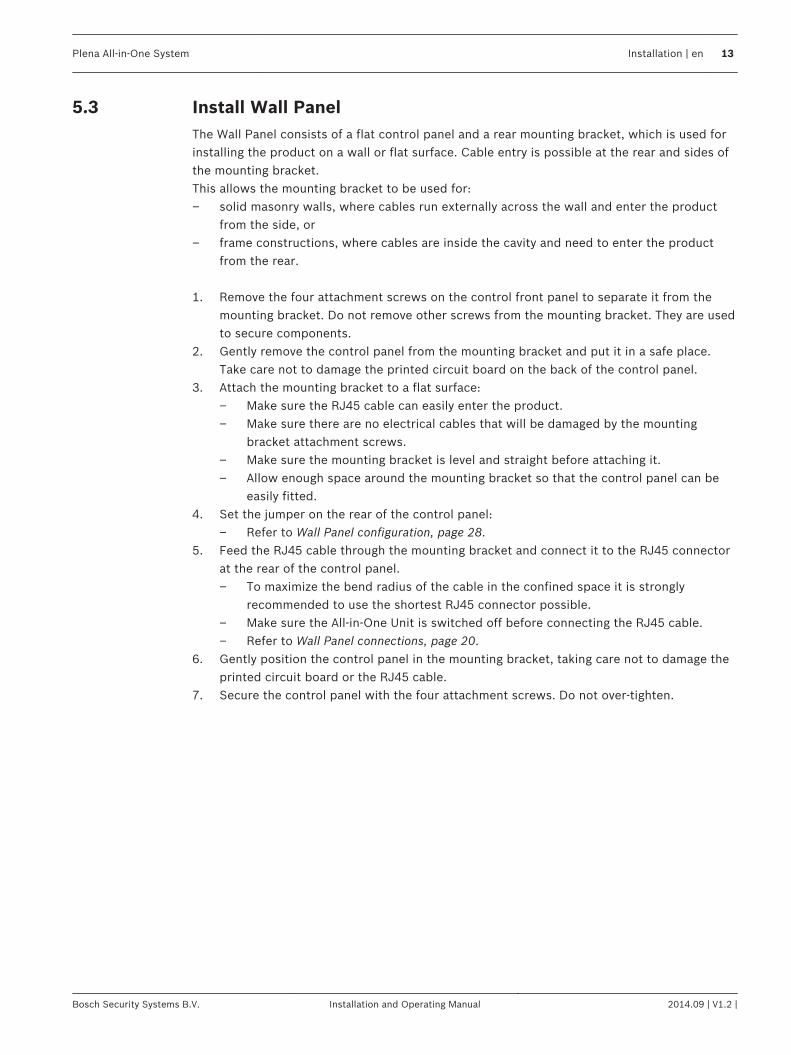
Install All-in-One Unit in 19“ rack (optional)The unit is intended for tabletop use. However, the unit can also be mounted in a 19” rack. For19" rack installation use:– The 19” rack mounting brackets that are supplied with the product.– The 6 screws and washers to replace the shorter screws that fix the cover to the chassis.– Standard rack screws and cage nuts (not delivered with the product).
Figure 5.1: Install unit in a 19” rack
Notice!
If you install the unit in a 19” rack, make sure:
- the tabletop feet are removed from the bottom of the unit.
- warm air expelled from the side of the unit can flow away.
- the unit cannot exceed the maximum operating temperature (+45°C ambient).
- there is sufficient ventilation and enough room, about 10 cm / 4”, behind the unit for cables
and connections.
Install Call Station1. The Call Station is used as a desktop device. Do not place this product where it is likely
to have liquid spilt on it.2. When installing the Call Station, do not:
– exceed the cable manufactures’ “bend radius” specifications,– install cabling in such a way that it becomes damaged or presents a hazard.
3. Make sure the RJ45 connectors have strong locking tabs, and cannot be inadvertentlypulled out once installed. Refer to Call Station connections, page 18.
Notice!
A maximum of six call stations can be configured for each All-in-One Unit.
The maximum cable distance from the All-in-One Unit to the last Call Station is 600 m.
5
5.1
5.2
12 en | Installation Plena All-in-One System
2014.09 | V1.2 | Installation and Operating Manual Bosch Security Systems B.V.
Install Wall PanelThe Wall Panel consists of a flat control panel and a rear mounting bracket, which is used forinstalling the product on a wall or flat surface. Cable entry is possible at the rear and sides ofthe mounting bracket.This allows the mounting bracket to be used for:– solid masonry walls, where cables run externally across the wall and enter the product
from the side, or– frame constructions, where cables are inside the cavity and need to enter the product
from the rear. 1. Remove the four attachment screws on the control front panel to separate it from the
mounting bracket. Do not remove other screws from the mounting bracket. They are usedto secure components.
2. Gently remove the control panel from the mounting bracket and put it in a safe place.Take care not to damage the printed circuit board on the back of the control panel.
3. Attach the mounting bracket to a flat surface:– Make sure the RJ45 cable can easily enter the product.– Make sure there are no electrical cables that will be damaged by the mounting
bracket attachment screws.– Make sure the mounting bracket is level and straight before attaching it.– Allow enough space around the mounting bracket so that the control panel can be
easily fitted.4. Set the jumper on the rear of the control panel:
– Refer to Wall Panel configuration, page 28.5. Feed the RJ45 cable through the mounting bracket and connect it to the RJ45 connector
at the rear of the control panel.– To maximize the bend radius of the cable in the confined space it is strongly
recommended to use the shortest RJ45 connector possible.– Make sure the All‑in‑One Unit is switched off before connecting the RJ45 cable.– Refer to Wall Panel connections, page 20.
6. Gently position the control panel in the mounting bracket, taking care not to damage theprinted circuit board or the RJ45 cable.
7. Secure the control panel with the four attachment screws. Do not over-tighten.
5.3
Plena All-in-One System Installation | en 13
Bosch Security Systems B.V. Installation and Operating Manual 2014.09 | V1.2 |
Connection
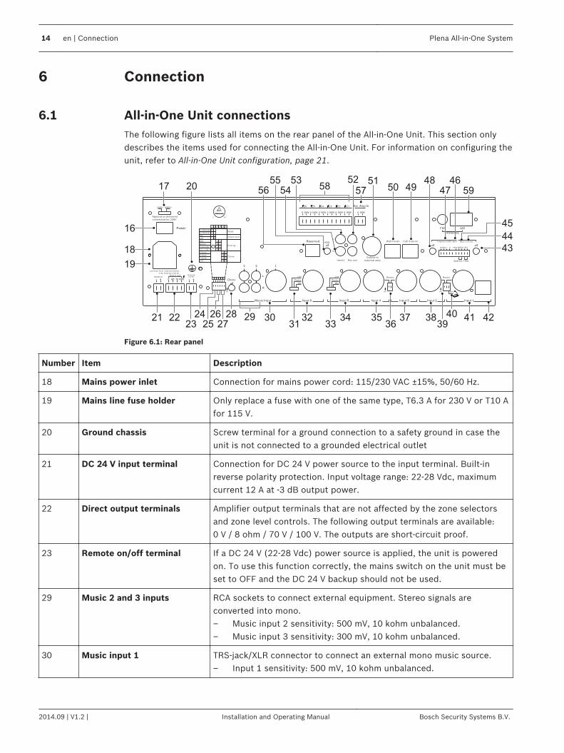
All‑in‑One Unit connectionsThe following figure lists all items on the rear panel of the All‑in‑One Unit. This section onlydescribes the items used for connecting the All‑in‑One Unit. For information on configuring theunit, refer to All-in-One Unit configuration, page 21.
17 205253
54
55
56 50 4948 46
47 59
51
57
45
44
43
424138373534322221
16
18
19
3040
3936333123 25
24 28
58
2927
26
Figure 6.1: Rear panel
Number Item Description
18 Mains power inlet Connection for mains power cord: 115/230 VAC ±15%, 50/60 Hz.
19 Mains line fuse holder Only replace a fuse with one of the same type, T6.3 A for 230 V or T10 Afor 115 V.
20 Ground chassis Screw terminal for a ground connection to a safety ground in case theunit is not connected to a grounded electrical outlet
21 DC 24 V input terminal Connection for DC 24 V power source to the input terminal. Built‑inreverse polarity protection. Input voltage range: 22‑28 Vdc, maximumcurrent 12 A at -3 dB output power.
22 Direct output terminals Amplifier output terminals that are not affected by the zone selectorsand zone level controls. The following output terminals are available:0 V / 8 ohm / 70 V / 100 V. The outputs are short-circuit proof.
23 Remote on/off terminal If a DC 24 V (22‑28 Vdc) power source is applied, the unit is poweredon. To use this function correctly, the mains switch on the unit must beset to OFF and the DC 24 V backup should not be used.
29 Music 2 and 3 inputs RCA sockets to connect external equipment. Stereo signals areconverted into mono.– Music input 2 sensitivity: 500 mV, 10 kohm unbalanced.– Music input 3 sensitivity: 300 mV, 10 kohm unbalanced.
30 Music input 1 TRS-jack/XLR connector to connect an external mono music source.– Input 1 sensitivity: 500 mV, 10 kohm unbalanced.
6
6.1
14 en | Connection Plena All-in-One System
2014.09 | V1.2 | Installation and Operating Manual Bosch Security Systems B.V.

Number Item Description
32 Input 6 – Microphone or Line input 6, with TRS-jack / XLR balanced signalinput connector.
– Microphone input 6 sensitivity: 1.5 mV, 600 ohm balanced.– Line input 6 sensitivity: 200 mV, 10 kohm balanced.
34 Input 5: – Microphone or Line input 5, with TRS-jack / XLR balanced signalinput connector.
– Microphone input 5 sensitivity: 1.5 mV, 600 ohm balanced.– Line input 5 sensitivity: 200 mV, 10 kohm balanced.
35 Input 4 – Microphone input 4, with TRS-jack / XLR balanced signal inputconnector.
– Microphone input 4 sensitivity: 1.5 mV, 600 ohm balanced.
37 Input 3 – Microphone input 3, with TRS-jack / XLR balanced signal inputconnector.
– Microphone input 3 sensitivity: 1.5 mV, 600 ohm balanced.
38 Input 2 – Microphone input 2, with TRS-jack / XLR balanced signal inputconnector.
– Microphone input 2 sensitivity: 1.5mV, 600 ohm balanced.
41 Input 1 – Microphone input 1 with TRS-jack / XLR balanced signal inputconnector.
– Microphone input 1 sensitivity: 1.5 mV, 600 ohm balanced
42 Input 1 RJ45 connector This input is intended for a PLE-1CS or PLE-1SCS all-call Call Station,which is connected with a Cat-5 cable and adapter box (supplied withthe unit). This allows for different length standard Cat-5 cables to beused.The PIN assignments of the RJ45 are as follows:– Pin 1: Audio+– Pin 2: Audio-– Pin 3: Ground– Pin 4: Trigger+– Pin 5: Trigger- (Ground)– Pins 6‑8: Not connectedA contact closure between pin 4 and 5 will activate the chime signal andgive priority to input 1. It will mute signals on other inputs, except forthe Telephone/Emergency input (46/47). The PTT switch (40) must beON.
44 8Ω MOH output 1 W, unbalanced Music-on-Hold output terminal for monitoring of theinternal music source or Music inputs 1-3 signals, selected by the musicsource selector (7).
45 Balanced MOH output 600 ohm, 1 Vrms, transformer isolated balanced Music-on-Hold signalfor monitoring of the internal music source or Music inputs 1-3 signals,selected by the music source selector (7).
46 Telephone/Emergency 100 Vinput
A balanced 100 V input, compatible with loudspeaker line signals. Thisinput has a gate function (VOX); when the signal level exceeds a -10 dBlevel, it gets the highest priority and overrides all other inputs.
Plena All-in-One System Connection | en 15
Bosch Security Systems B.V. Installation and Operating Manual 2014.09 | V1.2 |
Number Item Description
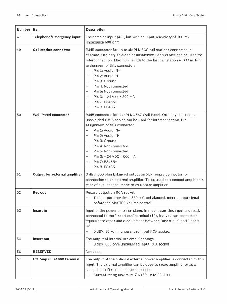
47 Telephone/Emergency input The same as input (46), but with an input sensitivity of 100 mV,impedance 600 ohm.
49 Call station connector RJ45 connector for up to six PLN-6CS call stations connected incascade. Ordinary shielded or unshielded Cat-5 cables can be used forinterconnection. Maximum length to the last call station is 600 m. Pinassignment of this connector:– Pin 1: Audio IN+– Pin 2: Audio IN-– Pin 3: Ground– Pin 4: Not connected– Pin 5: Not connected– Pin 6: + 24 Vdc < 800 mA– Pin 7: RS485+– Pin 8: RS485-
50 Wall Panel connector RJ45 connector for one PLN-4S6Z Wall Panel. Ordinary shielded orunshielded Cat-5 cables can be used for interconnection. Pinassignment of this connector:– Pin 1: Audio IN+– Pin 2: Audio IN-– Pin 3: Ground– Pin 4: Not connected– Pin 5: Not connected– Pin 6: + 24 VDC < 800 mA– Pin 7: RS485+– Pin 8: RS485-
51 Output for external amplifier 0 dBV, 600 ohm balanced output on XLR female connector forconnection to an external amplifier. To be used as a second amplifier incase of dual‑channel mode or as a spare amplifier.
52 Rec out Record output on RCA socket.– This output provides a 350 mV, unbalanced, mono output signal
before the MASTER volume control.
53 Insert in Input of the power amplifier stage. In most cases this input is directlyconnected to the “Insert out” terminal (54), but you can connect anequalizer or other audio equipment between “Insert out” and “Insertin”.– 0 dBV, 10 kohm unbalanced input RCA socket.
54 Insert out The output of internal pre-amplifier stage.– 0 dBV, 600 ohm unbalanced input RCA socket.
56 RESERVED Not used.
57 Ext Amp in 0-100V terminal The output of the optional external power amplifier is connected to thisinput. The external amplifier can be used as spare amplifier or as asecond amplifier in dual‑channel mode.– Current rating maximum 7 A (50 Hz to 20 kHz).
16 en | Connection Plena All-in-One System
2014.09 | V1.2 | Installation and Operating Manual Bosch Security Systems B.V.
Number Item Description
58 Zones 1-6 output terminals Output terminals for Zones 1 to 6. Each zone can be selectedindependently and has a 100 V‑0 V terminal.
59 AM/FM input termina Set of inputs for a 300 ohm AM antenna and a 75 ohm FM antenna. AnAM antenna and FM antenna connector are supplied with the unit.
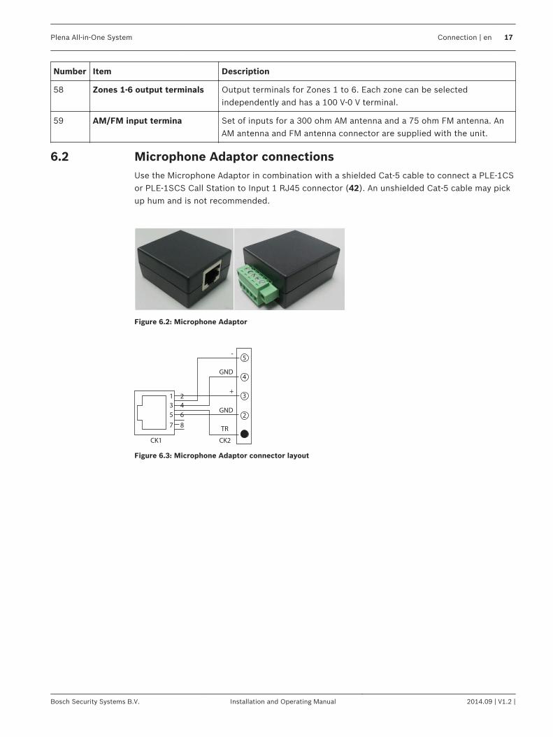
Microphone Adaptor connectionsUse the Microphone Adaptor in combination with a shielded Cat-5 cable to connect a PLE-1CSor PLE-1SCS Call Station to Input 1 RJ45 connector (42). An unshielded Cat-5 cable may pickup hum and is not recommended.
Figure 6.2: Microphone Adaptor
5
4
3
2
GND
GND
TR
CK2CK1
-
+1
3
5
7
2
4
6
8
Figure 6.3: Microphone Adaptor connector layout
6.2
Plena All-in-One System Connection | en 17
Bosch Security Systems B.V. Installation and Operating Manual 2014.09 | V1.2 |

Call Station connectionsThe following figure lists all items of the Call Station. This section only describes the itemsused for connecting the Call Station. For information on configuring and operating the CallStation, refer to– Call Station hardware configuration, page 24– Call Station software configuration, page 25– Call Station operation, page 38
7
9
1
2
4
5
126
8
11 10
3
Figure 6.4: PLN‑6CS Call Station connections
Number Item Description
6 Reserved Not used.
9 RJ45 connector (input)
Use a standard shielded or unshielded Cat-5 cable to connect the callstation to the All‑in‑One Unit or to the previous call station, connectedin cascade.
10 RJ45 connector (loop-through)
Use a standard shielded or unshielded Cat-5 cable to connect the callstation to the next call station, connected in cascade. The RJ45connectors (9) and (10) are in parallel and their functions can beinterchanged.The last Call Station in the chain must have a terminator plug in the freeRJ45 socket for best performance with long cables. A small terminatorplug that looks like an ordinary RJ45 connector is delivered with eachCall Station. See Delivered with products, page 11.When Call Stations are cascaded some terminators are left unused, asonly the last Call Station is terminated.
6.3
18 en | Connection Plena All-in-One System
2014.09 | V1.2 | Installation and Operating Manual Bosch Security Systems B.V.
Number Item Description
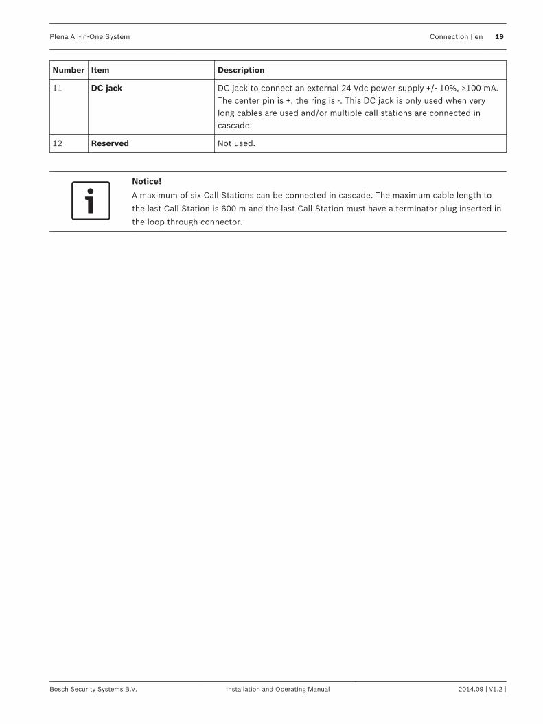
11 DC jack DC jack to connect an external 24 Vdc power supply +/- 10%, >100 mA.The center pin is +, the ring is -. This DC jack is only used when verylong cables are used and/or multiple call stations are connected incascade.
12 Reserved Not used.
Notice!
A maximum of six Call Stations can be connected in cascade. The maximum cable length to
the last Call Station is 600 m and the last Call Station must have a terminator plug inserted in
the loop through connector.
Plena All-in-One System Connection | en 19
Bosch Security Systems B.V. Installation and Operating Manual 2014.09 | V1.2 |
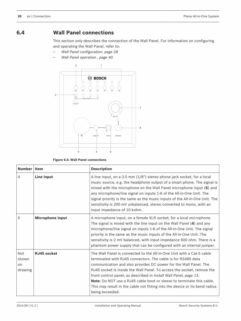
Wall Panel connectionsThis section only describes the connection of the Wall Panel. For information on configuringand operating the Wall Panel, refer to:– Wall Panel configuration, page 28– Wall Panel operation , page 40
12
3
7
8
645
Figure 6.5: Wall Panel connections
Number Item Description
4 Line input A line input, on a 3.5 mm (1/8") stereo phone jack socket, for a localmusic source, e.g. the headphone output of a smart phone. The signal ismixed with the microphone on the Wall Panel microphone input (5) andany microphone/line signal on inputs 1-6 of the All-in-One Unit. Thesignal priority is the same as the music inputs of the All-in-One Unit. Thesensitivity is 200 mV unbalanced, stereo converted to mono, with aninput impedance of 10 kohm.
5 Microphone input A microphone input, on a female XLR socket, for a local microphone.The signal is mixed with the line input on the Wall Panel (4) and anymicrophone/line signal on inputs 1-6 of the All‑in‑One Unit. The signalpriority is the same as the music inputs of the All‑in‑One Unit. Thesensitivity is 2 mV balanced, with input impedance 600 ohm. There is aphantom power supply that can be configured with an internal jumper.
Notshownondrawing
RJ45 socket The Wall Panel is connected to the All-in-One Unit with a Cat‑5 cableterminated with RJ45 connectors. The cable is for RS485 datacommunication and also provides DC power for the Wall Panel. TheRJ45 socket is inside the Wall Panel. To access the socket, remove thefront control panel, as described in Install Wall Panel, page 13.Note: Do NOT use a RJ45 cable boot or sleeve to terminate this cable.This may result in the cable not fitting into the device or its bend radiusbeing exceeded.
6.4
20 en | Connection Plena All-in-One System
2014.09 | V1.2 | Installation and Operating Manual Bosch Security Systems B.V.
Configuration
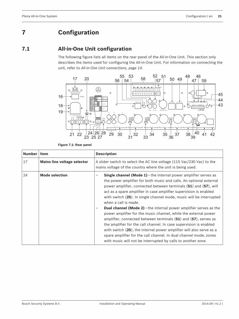
All-in-One Unit configurationThe following figure lists all items on the rear panel of the All‑in‑One Unit. This section onlydescribes the items used for configuring the All‑in‑One Unit. For information on connecting theunit, refer to All‑in‑One Unit connections, page 14.
17 205253
54
55
56 50 4948 46
47 59
51
57
45
44
43
424138373534322221
16
18
19
3040
3936333123 25
24 28
58
2927
26
Figure 7.1: Rear panel
Number Item Description
17 Mains line voltage selector A slider switch to select the AC line voltage (115 Vac/230 Vac) to themains voltage of the country where the unit is being used.
24 Mode selection – Single channel (Mode 1) - the internal power amplifier serves asthe power amplifier for both music and calls. An optional externalpower amplifier, connected between terminals (51) and (57), willact as a spare amplifier in case amplifier supervision is enabledwith switch (25). In single channel mode, music will be interruptedwhen a call is made.
– Dual channel (Mode 2) - the internal power amplifier serves as thepower amplifier for the music channel, while the external poweramplifier, connected between terminals (51) and (57), serves asthe amplifier for the call channel. In case supervision is enabledwith switch (25), the internal power amplifier will also serve as aspare amplifier for the call channel. In dual channel mode, zoneswith music will not be interrupted by calls to another zone.
7
7.1
Plena All-in-One System Configuration | en 21
Bosch Security Systems B.V. Installation and Operating Manual 2014.09 | V1.2 |
Number Item Description
25 Supervision (20 kHz) switch – When set to ON, an inaudible 20 kHz pilot tone is added to theaudio signal and the power amplifier supervision is enabled. Whenthe power amplifier fails and the pilot tone cannot be detectedanymore, the Fault LED will illuminate and, if available, the spareamplifier will take over. The pilot tone detection threshold on the100 V terminal is 10 V +3 dB/-1 dB.
– When the Supervision switch is set to OFF, no pilot tone is presentand no supervision or spare amplifier switching takes place. Powerconsumption and heat production is lowest when Supervision isOFF.
26 Priority switches Two switches are used to set the Priority. See Priority switches, page23.
27 Chime switches Two switches are used to set the chime tone. See Chime switches, page23. Only the chime for Microphone 1, PLE-1CS or PLE-1SCS, onterminal (42) is changed.
28 Chime level Adjusts chime output level. Only the chime level for Microphone 1,PLE-1CS or PLE-1SCS, on terminal (42) is changed.
31 Input 6 Line/Phantom/Microphone selector
Switch to select the sensitivity and phantom power of Input 6. ThePhantom mode is valid for microphone sensitivity only (Phantom: 18 V@ no load).
33 Input 5 Line/Phantom/Microphone selector
Switch to select the sensitivity and phantom power of Input 5. ThePhantom mode is valid for microphone sensitivity only (Phantom: 18 V@ no load).
36 Phantom power ON/OFFswitch for Inputs 3 and 4independently
Switch to set the phantom power to ON (Phantom: 18 V @ no load).
39 Phantom power ON/OFFswitch for Inputs 1 and 2independently
Switch to set the phantom power to ON (Phantom: 18 V @ no load).
40 Press To Talk (PTT) switch – PTT switch set to ON: A microphone connected to terminal (41)will be disabled, but an all-call Call Station PLE-1CS or PLE-1SCS,connected to terminal (42), allows speech to all zones and anoptional chime signal.
– PTT switch set to OFF: Microphone input 1 is enabled. A connectedPLE-1CS or PLE-1SCS is not disabled but just mixed withMicrophone input 1, without a chime signal.
43 MOH level adjustment Adjusts the output level of the “Music On Hold” signal on outputs (44)and (45).
22 en | Configuration Plena All-in-One System
2014.09 | V1.2 | Installation and Operating Manual Bosch Security Systems B.V.
Number Item Description
48 Telephone/Emergency leveladjustment
Adjusts the output level for the Telephone/Emergency signal applied toinputs (46) and/or (47). This adjustment does not change the sensitivityof the input gate (VOX).
55 Ducking level Attenuates the music level from the internal music source or Musicinputs 1-3 when the priority mute function is activated.– The ducking attenuation is adjustable in the range 0 to -60 dB.
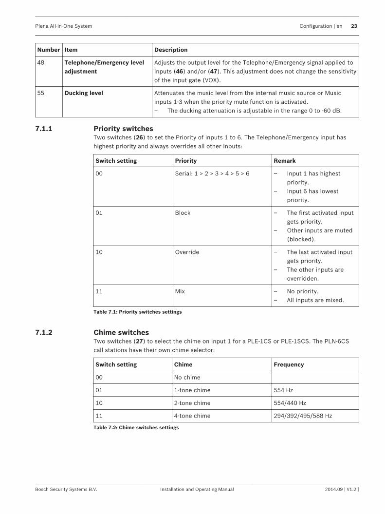
Priority switchesTwo switches (26) to set the Priority of inputs 1 to 6. The Telephone/Emergency input hashighest priority and always overrides all other inputs:
Switch setting Priority Remark
00 Serial: 1 > 2 > 3 > 4 > 5 > 6 – Input 1 has highestpriority.
– Input 6 has lowestpriority.
01 Block – The first activated inputgets priority.
– Other inputs are muted(blocked).
10 Override – The last activated inputgets priority.
– The other inputs areoverridden.
11 Mix – No priority.– All inputs are mixed.
Table 7.1: Priority switches settings
Chime switchesTwo switches (27) to select the chime on input 1 for a PLE-1CS or PLE-1SCS. The PLN-6CScall stations have their own chime selector:
Switch setting Chime Frequency
00 No chime
01 1-tone chime 554 Hz
10 2-tone chime 554/440 Hz
11 4-tone chime 294/392/495/588 Hz
Table 7.2: Chime switches settings
7.1.1
7.1.2
Plena All-in-One System Configuration | en 23
Bosch Security Systems B.V. Installation and Operating Manual 2014.09 | V1.2 |
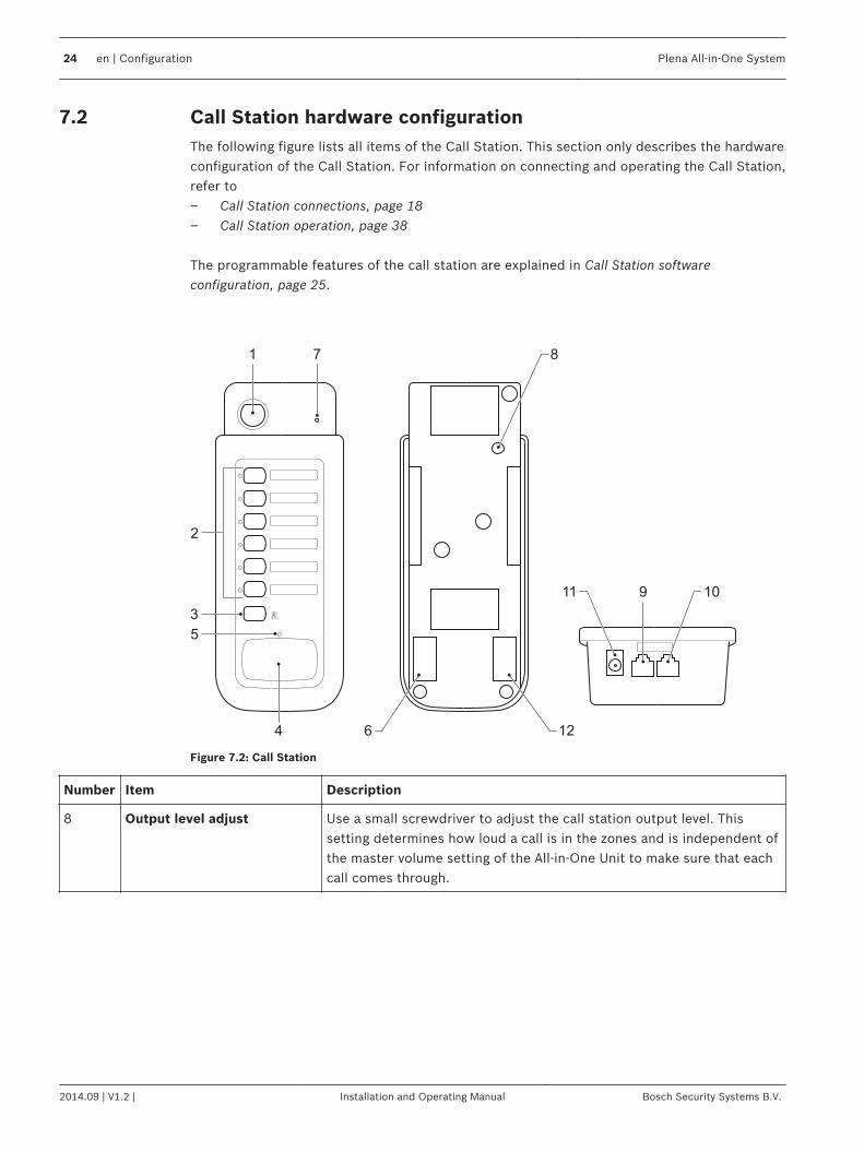
Call Station hardware configurationThe following figure lists all items of the Call Station. This section only describes the hardwareconfiguration of the Call Station. For information on connecting and operating the Call Station,refer to– Call Station connections, page 18– Call Station operation, page 38 The programmable features of the call station are explained in Call Station softwareconfiguration, page 25.
7
9
1
2
4
5
126
8
11 10
3
Figure 7.2: Call Station
Number Item Description
8 Output level adjust Use a small screwdriver to adjust the call station output level. Thissetting determines how loud a call is in the zones and is independent ofthe master volume setting of the All‑in‑One Unit to make sure that eachcall comes through.
7.2
24 en | Configuration Plena All-in-One System
2014.09 | V1.2 | Installation and Operating Manual Bosch Security Systems B.V.
Call Station software configuration
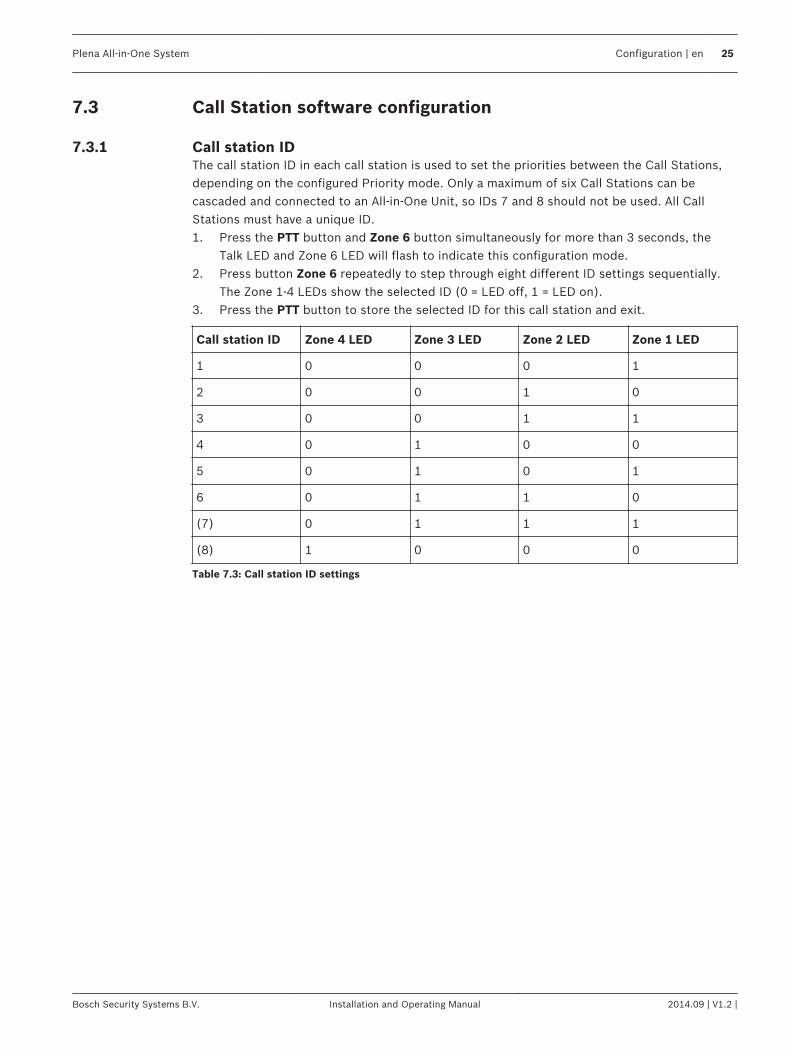
Call station IDThe call station ID in each call station is used to set the priorities between the Call Stations,depending on the configured Priority mode. Only a maximum of six Call Stations can becascaded and connected to an All‑in‑One Unit, so IDs 7 and 8 should not be used. All CallStations must have a unique ID.1. Press the PTT button and Zone 6 button simultaneously for more than 3 seconds, the
Talk LED and Zone 6 LED will flash to indicate this configuration mode.2. Press button Zone 6 repeatedly to step through eight different ID settings sequentially.
The Zone 1-4 LEDs show the selected ID (0 = LED off, 1 = LED on).3. Press the PTT button to store the selected ID for this call station and exit.
Call station ID Zone 4 LED Zone 3 LED Zone 2 LED Zone 1 LED
1 0 0 0 1
2 0 0 1 0
3 0 0 1 1
4 0 1 0 0
5 0 1 0 1
6 0 1 1 0
(7) 0 1 1 1
(8) 1 0 0 0
Table 7.3: Call station ID settings
7.3
7.3.1
Plena All-in-One System Configuration | en 25
Bosch Security Systems B.V. Installation and Operating Manual 2014.09 | V1.2 |
Microphone sensitivityThe setting for the microphone sensitivity sets the gain of the microphone amplifier in front ofthe signal limiter. The output level preset (item (8) in Call Station hardware configuration, page24) sets the volume of the output after the signal limiter. Note that these are two differentthings. The output level sets the maximum loudness of the announcements in the zones, whilethe sensitivity setting compensates for loud or soft speaking voices. Soft speakers or speakersthat keep much distance from the microphone should use a high sensitivity. Be careful withselecting a high sensitivity in combination with a high output level, when the zoneloudspeakers are in the same area as the call station. This might result in acoustic feedback(howling).1. Press the PTT button and Zone 5 button simultaneously for more than 3 seconds, the
Talk LED and Zone 5 LED will flash to indicate this configuration mode.2. Press button Zone 5 repeatedly to step through the six different sensitivity settings
sequentially. The Zone 1-3 LEDs show the selected sensitivity (0 = LED off, 1 = LED on).3. Press the PTT button to store the selected sensitivity and exit.
Sensitivity Zone 3 LED Zone 2 LED Zone 1 LED
1 0 0 1
2 0 1 0
3 0 1 1
4 1 0 0
5 1 0 1
6 (max) 1 1 0
Table 7.4: Microphone sensitivity settings
Speech filterThe speech filter removes the lowest frequencies of the speech signal, that are especiallypresent when talking close into the microphone. Removing the lowest frequencies reduces therisk for amplifier overloading and in general improves intelligibility.1. Press the PTT button and Zone 2 button simultaneously for more than 3 seconds, the
Talk LED and Zone 2 LED will flash to indicate this configuration mode.2. Press button Zone 2 to toggle between a flat frequency response and the filtered
response. The Zone 2 LED shows the selected filter setting (0 = LED off, 1 = LED on).3. Press the PTT button to store the speech filter setting and exit.
Speech filter Zone 2 LED Remark
Filtered response 0 Low cut @ 315 Hz (-3 dB), 6 dB/octave
Flat response 1
Table 7.5: Speech filter settings
Priority modeThis setting determines what happens when more than one Call Station is connected to theAll‑in‑One Unit. For consistent behavior make sure that all connected Call Stations use thesame setting.
7.3.2
7.3.3
7.3.4
26 en | Configuration Plena All-in-One System
2014.09 | V1.2 | Installation and Operating Manual Bosch Security Systems B.V.
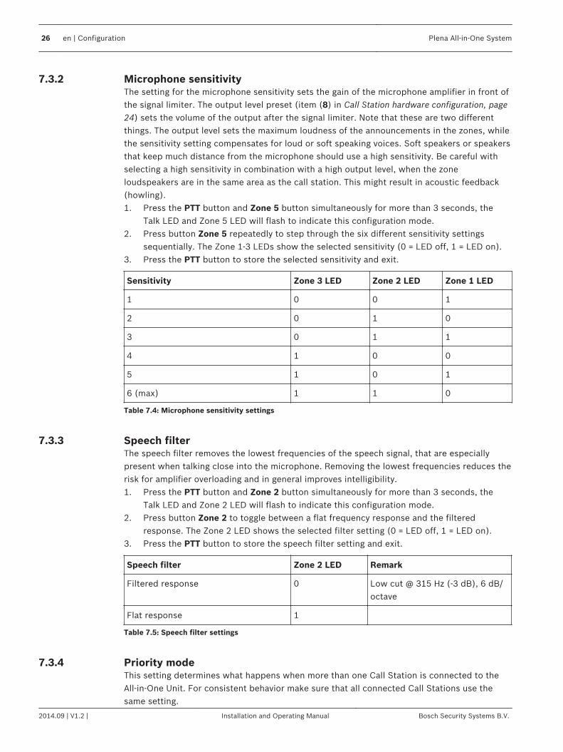
1. Press the PTT button and Zone 4 button simultaneously for more than 3 seconds, theTalk LED and Zone 4 LED will flash to indicate this configuration mode.
2. Press button Zone 4 repeatedly to step through the four different priority modessequentially. The Zone 1-3 LEDs show the selected priority mode (0 = LED off, 1 = LEDon).
3. Press the PTT button to store the selected priority mode and exit.
Priority mode Zone 3 LED Zone 2 LED Zone 1 LED
Serial priority: 1>2>3>4>5>6, CallStation 1 has highest priority
0 0 1
Blocking priority: the active CallStation keeps priority
0 1 0
Override mode: the last Call stationwill get priority
0 1 1
Mixing mode: all Call Stations haveequal priority and audio is mixed
1 0 0
Table 7.6: Priority mode settings
Chime selectionThis setting selects the type of chime at the start of a call to draw the attention of theaudience, in order not to miss the first words of the announcement.1. Press the PTT button and Zone 3 button simultaneously for more than 3 seconds, the
Talk LED and Zone 3 LED will flash to indicate this configuration mode.2. Press button Zone 3 repeatedly to step through the four different chime settings
sequentially. The Zone 1 and 2 LEDs show the chime setting (0 = LED off, 1 = LED on).3. Press the PTT button to store the selected chime setting and exit.
Chime setting Zone 2 LED Zone 1 LED
No chime 0 0
1-tone chime (554 Hz) 0 1
2-tone chime (554/440 Hz) 1 0
4-tone chime (294/392/495/588 Hz) 1 1
Table 7.7: Chine selection settings
Zone group creationThis configuration creates sets of zones that are assigned to a single zone button, to speed upthe selection of zones that are frequently addressed together. Note that when a zone group isassigned to a zone button, this button is not available anymore for direct selection of thatzone.1. Press the PTT button and Zone 1 button simultaneously for more than 3 seconds, all
Zone 1-6 LEDs will flash to indicate this configuration mode.2. Press one button (from buttons Zone 1-6) to store the zone group setting. All Zone 1-6
LEDs flash again. Then select the required zones for this zone group.3. Press the PTT button to store the created zone groups and exit.
7.3.5
7.3.6
Plena All-in-One System Configuration | en 27
Bosch Security Systems B.V. Installation and Operating Manual 2014.09 | V1.2 |
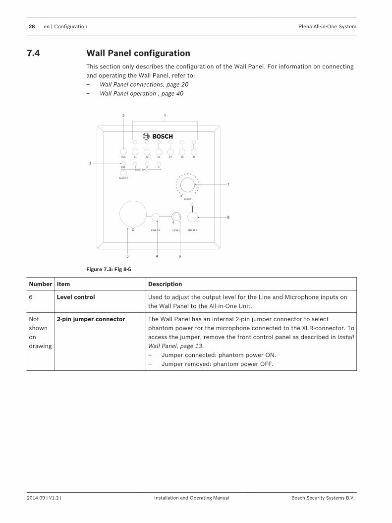
Wall Panel configurationThis section only describes the configuration of the Wall Panel. For information on connectingand operating the Wall Panel, refer to:– Wall Panel connections, page 20– Wall Panel operation , page 40
12
3
7
8
645
Figure 7.3: Fig 8-5
Number Item Description
6 Level control Used to adjust the output level for the Line and Microphone inputs onthe Wall Panel to the All-in-One Unit.
Notshownondrawing
2-pin jumper connector The Wall Panel has an internal 2-pin jumper connector to selectphantom power for the microphone connected to the XLR-connector. Toaccess the jumper, remove the front control panel as described in InstallWall Panel, page 13.– Jumper connected: phantom power ON.– Jumper removed: phantom power OFF.
7.4
28 en | Configuration Plena All-in-One System
2014.09 | V1.2 | Installation and Operating Manual Bosch Security Systems B.V.
Operation
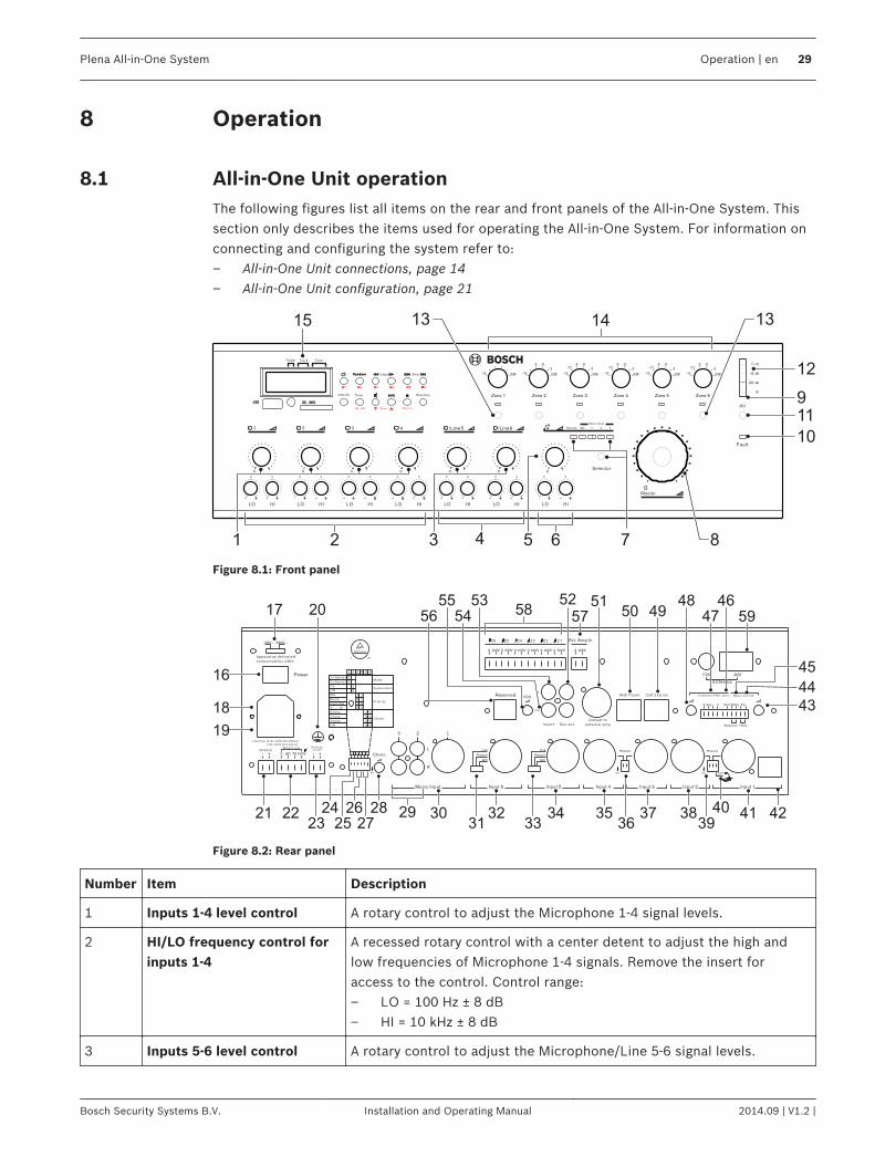
All-in-One Unit operationThe following figures list all items on the rear and front panels of the All‑in‑One System. Thissection only describes the items used for operating the All‑in‑One System. For information onconnecting and configuring the system refer to:– All‑in‑One Unit connections, page 14– All-in-One Unit configuration, page 21
- + - + - + - + - + - + - +- + - + - + - + - + - + - +
8
1313
7
15 14
12
9
11
10
642 531
Figure 8.1: Front panel
17 205253
54
55
56 50 4948 46
47 59
51
57
45
44
43
424138373534322221
16
18
19
3040
3936333123 25
24 28
58
2927
26
Figure 8.2: Rear panel
Number Item Description
1 Inputs 1‑4 level control A rotary control to adjust the Microphone 1‑4 signal levels.
2 HI/LO frequency control forinputs 1‑4
A recessed rotary control with a center detent to adjust the high andlow frequencies of Microphone 1‑4 signals. Remove the insert foraccess to the control. Control range:– LO = 100 Hz ± 8 dB– HI = 10 kHz ± 8 dB
3 Inputs 5‑6 level control A rotary control to adjust the Microphone/Line 5‑6 signal levels.
8
8.1
Plena All-in-One System Operation | en 29
Bosch Security Systems B.V. Installation and Operating Manual 2014.09 | V1.2 |

Number Item Description
4 HI/LO frequency control forinputs 5‑6
A recessed rotary control with a center detent to adjust the high andlow frequencies of Microphone 5‑6 signals. Remove the insert foraccess to the control. Control range:– LO = 100 Hz ± 8 dB– HI = 10 kHz ± 8 dB
5 Music level control A rotary control to adjust the level of the selected music source.
6 HI/LO control for musicinputs 1‑3
A recessed rotary control with a center detent to adjust the high andlow frequency of the selected music source. Remove the insert foraccess to the control. Control range:– LO = 100 Hz ± 8 dB– HI = 10 kHz ± 8 dB
7 Music source selector andindicators
Press the Selector button repeatedly to select sequentially between theinternal music source (SD/USB/tuner) and one of the three musicinputs on the rear panel. A green LED shows the source selected.When a PLN-4S6Z Wall Panel is connected and enabled to have control,the Remote LED is ON. Pressing the Selector button will then firstdisable the Wall Panel before switching to the next music input. Withthe Selector button the internal music player can be selected with andwithout Wall Panel control. For the other music inputs, control by theWall Panel must be enabled from the Wall Panel itself.
8 Master volume control A rotary control to adjust the overall output signal of the unit.– The master volume control has no effect on the volume of the
PLN-6CS Call Station and on the volume of the Telephone/Emergency signal. The PLN-6CS has its own volume setting thatmust be set for best intelligibility. The Telephone/Emergency inputalso has its own volume setting (48).
– The volume level of all other inputs is controlled by the mastervolume control of either the All-in-One Unit or the Wall Panel.
9 Power LED The green power LED indicates power on.
10 Fault LED The Fault LED lights up amber to indicate that the pilot tone detectingcircuit has not found a pilot tone at the output of the internal orexternal amplifier. This will only occur when the unit is in supervisorymode, see item (25) in All-in-One Unit configuration, page 21.Note: The Plena All‑in‑One System is not certified for voice alarmpurposes. When there is no special reason to supervise the built-in orexternal amplifier, it is recommended to switch off supervision toreduce the power consumption of the device.
11 All (zones) switch andindicator
When the All switch is pressed, all zones are switched on and all outputzone LEDs light up
12 LED VU meter Indicates the output signal level. Accuracy is between +0 / -3 dB, where:– 0 dB = red– -6 dB = amber– -20 dB = amber– Power on = green
30 en | Operation Plena All-in-One System
2014.09 | V1.2 | Installation and Operating Manual Bosch Security Systems B.V.
Number Item Description
13 Zone 1 - 6 select switchesand indicators
Push a switch to select an output zone. Each zone can be selectedindependently. When a zone is selected the corresponding green LED ison, and audio signals are routed to that zone. If a call is made from acall station with locally selected zones, or when a signal is detected onthe Telephone/Emergency input, the green LEDs of all addressed zoneswill flash. When a call has ended, the zone status returns to its previousstate.
14 Zone output attenuators Rotary controls to attenuate the output level of each zoneindependently, using the following attenuation steps:0dB / -3dB / -6dB / -9dB / -12dB / -15dB.
15 Built-in music source The music source comprises an AM/FM tuner and a USB/SD card player.See Internal music unit, page 32.
16 Power switch Switches the unit power on and off:– I = unit power ON– 0 = unit power OFF– Caution!
Risk of potential damage to unit. Before connecting power, alwayscheck the voltage selector (17) (on the rear panel of the unit) toensure it is set to the correct country voltage.
Plena All-in-One System Operation | en 31
Bosch Security Systems B.V. Installation and Operating Manual 2014.09 | V1.2 |
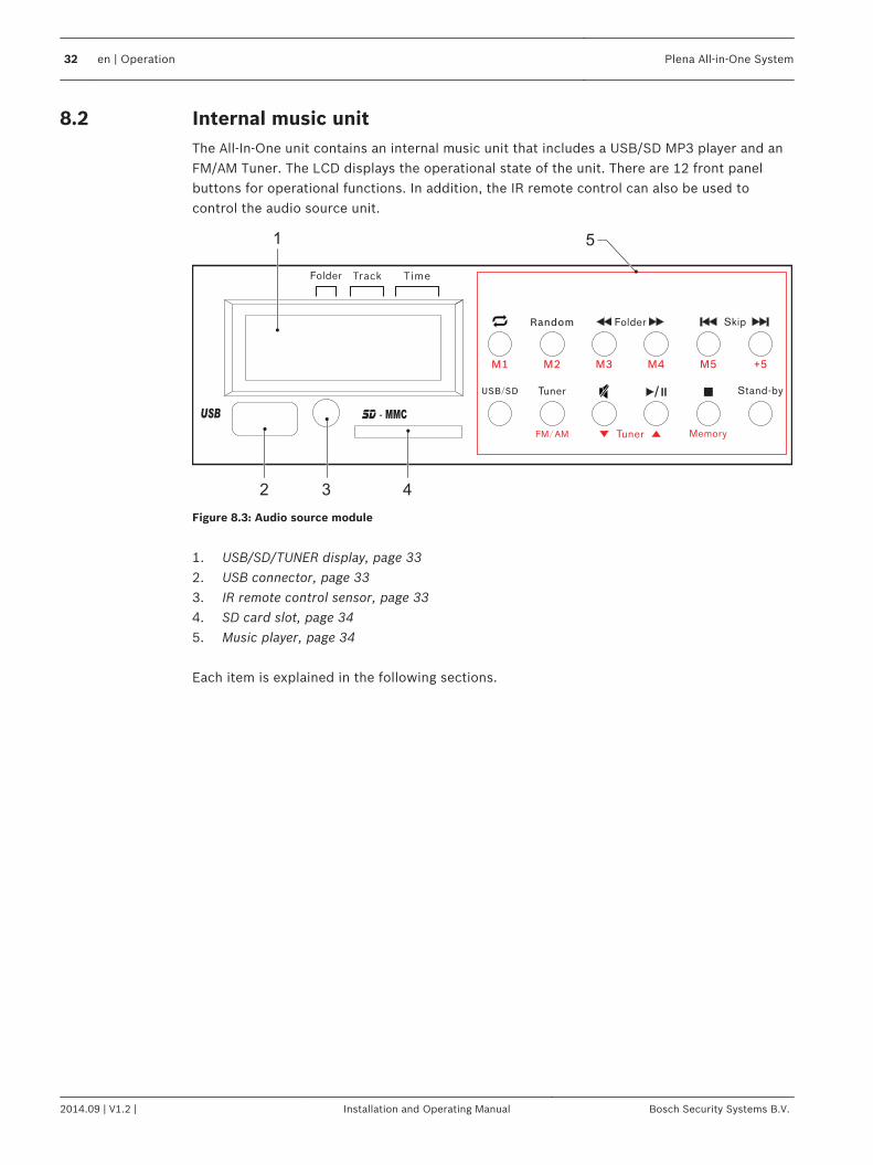
Internal music unitThe All‑In‑One unit contains an internal music unit that includes a USB/SD MP3 player and anFM/AM Tuner. The LCD displays the operational state of the unit. There are 12 front panelbuttons for operational functions. In addition, the IR remote control can also be used tocontrol the audio source unit.
5
2 3 4
1
Figure 8.3: Audio source module
1. USB/SD/TUNER display, page 332. USB connector, page 333. IR remote control sensor, page 334. SD card slot, page 345. Music player, page 34 Each item is explained in the following sections.
8.2
32 en | Operation Plena All-in-One System
2014.09 | V1.2 | Installation and Operating Manual Bosch Security Systems B.V.

USB/SD/TUNER display
CH+ 5
RANDOMREPEATM3
CD FM ST
AM
FOLDERALL1
H I K
B
G
A C D E
F
J
Figure 8.4: SD/USB/TUNER LCD display (1)
(A) MP3 indicator(B) Repeat 1 song or Repeat All indicator(C) Repeat folder indicator(D) Randomize indicator(E) +5 preset indicator(F) CH (channel) indicator(G) Play or Pause status(H) Radio band indicator(I) Radio FM stereo indicator(J) Frequency, or song number or folder number(K) Duration time of song or preset status
USB connectorOnly use a USB memory stick or flash drive with a maximum current consumption of 500 mA.Do not connect USB hard disks. Maximum supported memory size is 32 GB.To use the USB connector (2):1. Plug‑in the USB flash drive to the USB connector.2. Press Standby to power on the music source and/or press USB/SD to select the USB
device.3. While the music player is reading the content of the USB device, the LCD displays 'USB'
flashing.– If the content reading is successful, the first track found will be played.– If the content reading is unsuccessful, the LCD displays ‘none’.
4. When playing from the USB flash drive has finished, the player will resume playback fromthe tuner automatically.
IR remote control sensorThe IR sensor (3) receives an IR signal from the remote control supplied with the unit. Themaximum distance in an open field is 10 m, and a direct line of sight is needed.
8.2.1
8.2.2
8.2.3
Plena All-in-One System Operation | en 33
Bosch Security Systems B.V. Installation and Operating Manual 2014.09 | V1.2 |
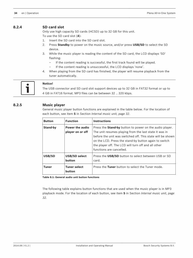
SD card slotOnly use high capacity SD cards (HCSD) up to 32 GB for this unit.To use the SD card slot (4):1. Insert the SD card into the SD card slot.2. Press Standby to power on the music source, and/or press USB/SD to select the SD
device.3. While the music player is reading the content of the SD card, the LCD displays 'SD'
flashing:– If the content reading is successful, the first track found will be played.– If the content reading is unsuccessful, the LCD displays ‘none’.
4. When playing from the SD card has finished, the player will resume playback from thetuner automatically.
Notice!
The USB connector and SD card slot support devices up to 32 GB in FAT32 format or up to
4 GB in FAT16 format. MP3 files can be between 32 .. 320 kbps.
Music playerGeneral music player button functions are explained in the table below. For the location ofeach button, see item 5 in Section Internal music unit, page 32.
Button Function Instructions
Stand-by Power the audioplayer on or off
Press the Stand-by button to power on the audio player.The unit resumes playing from the last state it was inbefore the unit was switched off. This state will be shownon the LCD. Press the stand-by button again to switchthe player off. The LCD will turn off and all otherfunctions are cancelled.
USB/SD USB/SD selectbutton
Press the USB/SD button to select between USB or SDcard.
Tuner Tuner selectbutton
Press the Tuner button to select the Tuner mode.
Table 8.1: General audio unit button functions
The following table explains button functions that are used when the music player is in MP3playback mode. For the location of each button, see item 5 in Section Internal music unit, page32.
8.2.4
8.2.5
34 en | Operation Plena All-in-One System
2014.09 | V1.2 | Installation and Operating Manual Bosch Security Systems B.V.
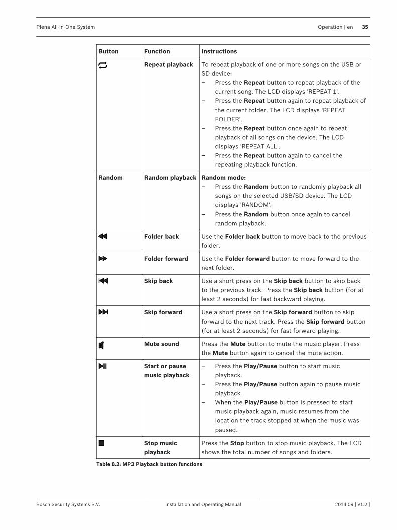
Button Function Instructions
Repeat playback To repeat playback of one or more songs on the USB orSD device:– Press the Repeat button to repeat playback of the
current song. The LCD displays 'REPEAT 1'.– Press the Repeat button again to repeat playback of
the current folder. The LCD displays 'REPEATFOLDER'.
– Press the Repeat button once again to repeatplayback of all songs on the device. The LCDdisplays 'REPEAT ALL'.
– Press the Repeat button again to cancel therepeating playback function.
Random Random playback Random mode:– Press the Random button to randomly playback all
songs on the selected USB/SD device. The LCDdisplays 'RANDOM'.
– Press the Random button once again to cancelrandom playback.
Folder back Use the Folder back button to move back to the previousfolder.
Folder forward Use the Folder forward button to move forward to thenext folder.
Skip back Use a short press on the Skip back button to skip backto the previous track. Press the Skip back button (for atleast 2 seconds) for fast backward playing.
Skip forward Use a short press on the Skip forward button to skipforward to the next track. Press the Skip forward button(for at least 2 seconds) for fast forward playing.
Mute sound Press the Mute button to mute the music player. Pressthe Mute button again to cancel the mute action.
Start or pausemusic playback
– Press the Play/Pause button to start musicplayback.
– Press the Play/Pause button again to pause musicplayback.
– When the Play/Pause button is pressed to startmusic playback again, music resumes from thelocation the track stopped at when the music waspaused.
Stop musicplayback
Press the Stop button to stop music playback. The LCDshows the total number of songs and folders.
Table 8.2: MP3 Playback button functions
Plena All-in-One System Operation | en 35
Bosch Security Systems B.V. Installation and Operating Manual 2014.09 | V1.2 |
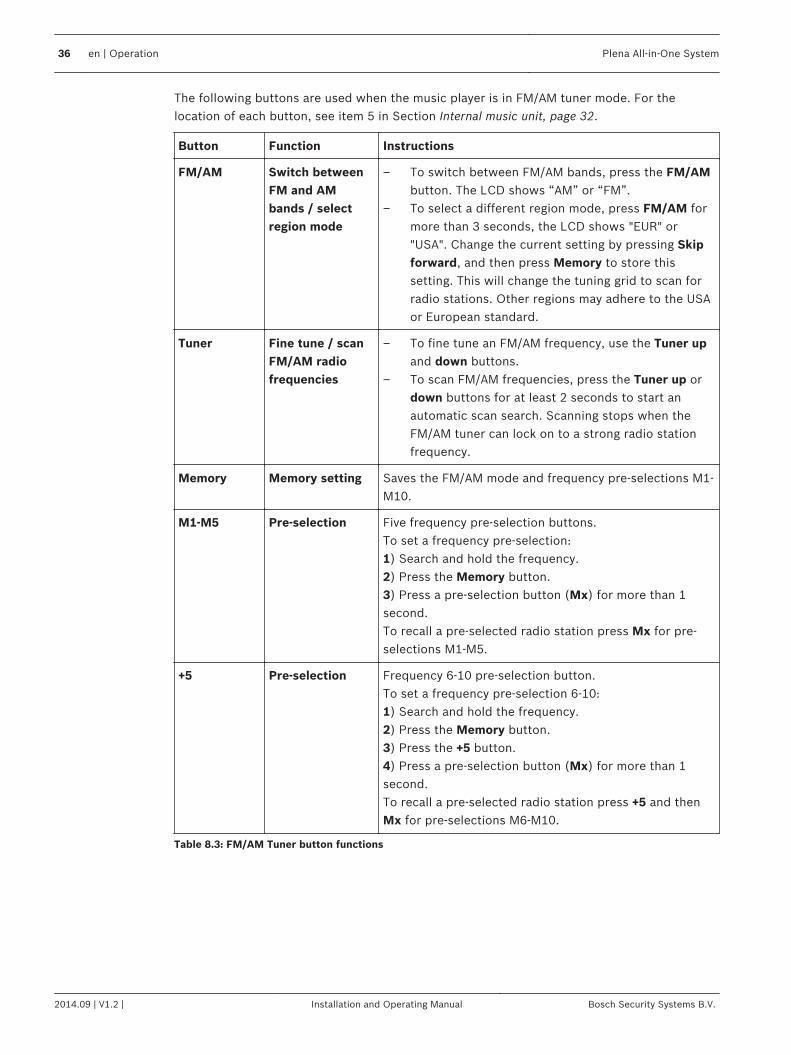
The following buttons are used when the music player is in FM/AM tuner mode. For thelocation of each button, see item 5 in Section Internal music unit, page 32.
Button Function Instructions
FM/AM Switch betweenFM and AMbands / selectregion mode
– To switch between FM/AM bands, press the FM/AMbutton. The LCD shows “AM” or “FM”.
– To select a different region mode, press FM/AM formore than 3 seconds, the LCD shows "EUR" or"USA". Change the current setting by pressing Skipforward, and then press Memory to store thissetting. This will change the tuning grid to scan forradio stations. Other regions may adhere to the USAor European standard.
Tuner Fine tune / scanFM/AM radiofrequencies
– To fine tune an FM/AM frequency, use the Tuner upand down buttons.
– To scan FM/AM frequencies, press the Tuner up ordown buttons for at least 2 seconds to start anautomatic scan search. Scanning stops when theFM/AM tuner can lock on to a strong radio stationfrequency.
Memory Memory setting Saves the FM/AM mode and frequency pre-selections M1-M10.
M1‑M5 Pre‑selection Five frequency pre‑selection buttons.To set a frequency pre‑selection:1) Search and hold the frequency.2) Press the Memory button.3) Press a pre‑selection button (Mx) for more than 1second.To recall a pre-selected radio station press Mx for pre-selections M1-M5.
+5 Pre‑selection Frequency 6‑10 pre‑selection button.To set a frequency pre‑selection 6‑10:1) Search and hold the frequency.2) Press the Memory button.3) Press the +5 button.4) Press a pre‑selection button (Mx) for more than 1second.To recall a pre-selected radio station press +5 and thenMx for pre-selections M6-M10.
Table 8.3: FM/AM Tuner button functions
36 en | Operation Plena All-in-One System
2014.09 | V1.2 | Installation and Operating Manual Bosch Security Systems B.V.
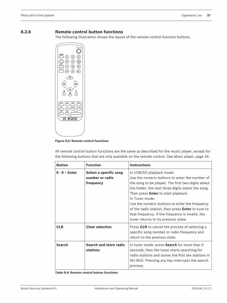
Remote control button functionsThe following illustration shows the layout of the remote control function buttons.
Figure 8.5: Remote control functions
All remote control button functions are the same as described for the music player, except forthe following buttons that are only available on the remote control. See Music player, page 34.
Button Function Instructions
0 - 9 + Enter Select a specific songnumber or radiofrequency
In USB/SD playback mode:Use the numeric buttons to enter the number ofthe song to be played. The first two digits selectthe folder; the next three digits select the song.Then press Enter to start playback.In Tuner mode:Use the numeric buttons to enter the frequencyof the radio station, then press Enter to tune tothat frequency. If the frequency is invalid, thetuner returns to its previous state.
CLR Clear selection Press CLR to cancel the process of selecting aspecific song number or radio frequency andreturn to the previous state.
Search Search and store radiostations
In tuner mode: press Search for more than 5seconds, then the tuner starts searching forradio stations and stores the first ten stations inM1-M10. Pressing any key interrupts the searchprocess.
Table 8.4: Remote control button functions
8.2.6
Plena All-in-One System Operation | en 37
Bosch Security Systems B.V. Installation and Operating Manual 2014.09 | V1.2 |
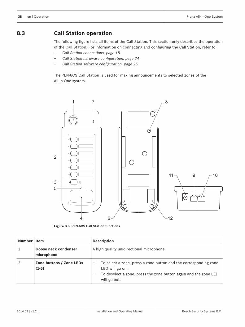
Call Station operationThe following figure lists all items of the Call Station. This section only describes the operationof the Call Station. For information on connecting and configuring the Call Station, refer to:– Call Station connections, page 18– Call Station hardware configuration, page 24– Call Station software configuration, page 25 The PLN‑6CS Call Station is used for making announcements to selected zones of theAll‑in‑One system.
7
9
1
2
4
5
126
8
11 10
3
Figure 8.6: PLN‑6CS Call Station functions
Number Item Description
1 Goose neck condensermicrophone
A high quality unidirectional microphone.
2 Zone buttons / Zone LEDs(1-6)
– To select a zone, press a zone button and the corresponding zoneLED will go on.
– To deselect a zone, press the zone button again and the zone LEDwill go out.
8.3
38 en | Operation Plena All-in-One System
2014.09 | V1.2 | Installation and Operating Manual Bosch Security Systems B.V.
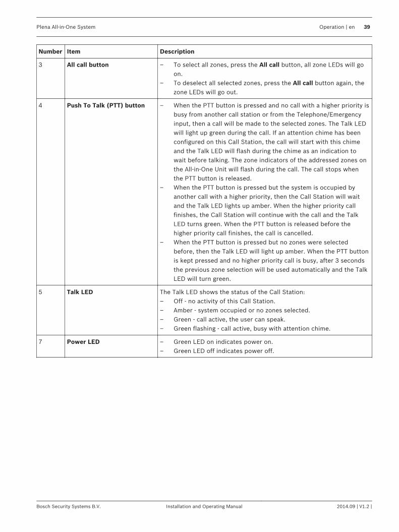
Number Item Description
3 All call button – To select all zones, press the All call button, all zone LEDs will goon.
– To deselect all selected zones, press the All call button again, thezone LEDs will go out.
4 Push To Talk (PTT) button – When the PTT button is pressed and no call with a higher priority isbusy from another call station or from the Telephone/Emergencyinput, then a call will be made to the selected zones. The Talk LEDwill light up green during the call. If an attention chime has beenconfigured on this Call Station, the call will start with this chimeand the Talk LED will flash during the chime as an indication towait before talking. The zone indicators of the addressed zones onthe All‑in‑One Unit will flash during the call. The call stops whenthe PTT button is released.
– When the PTT button is pressed but the system is occupied byanother call with a higher priority, then the Call Station will waitand the Talk LED lights up amber. When the higher priority callfinishes, the Call Station will continue with the call and the TalkLED turns green. When the PTT button is released before thehigher priority call finishes, the call is cancelled.
– When the PTT button is pressed but no zones were selectedbefore, then the Talk LED will light up amber. When the PTT buttonis kept pressed and no higher priority call is busy, after 3 secondsthe previous zone selection will be used automatically and the TalkLED will turn green.
5 Talk LED The Talk LED shows the status of the Call Station:– Off - no activity of this Call Station.– Amber - system occupied or no zones selected.– Green - call active, the user can speak.– Green flashing - call active, busy with attention chime.
7 Power LED – Green LED on indicates power on.– Green LED off indicates power off.
Plena All-in-One System Operation | en 39
Bosch Security Systems B.V. Installation and Operating Manual 2014.09 | V1.2 |
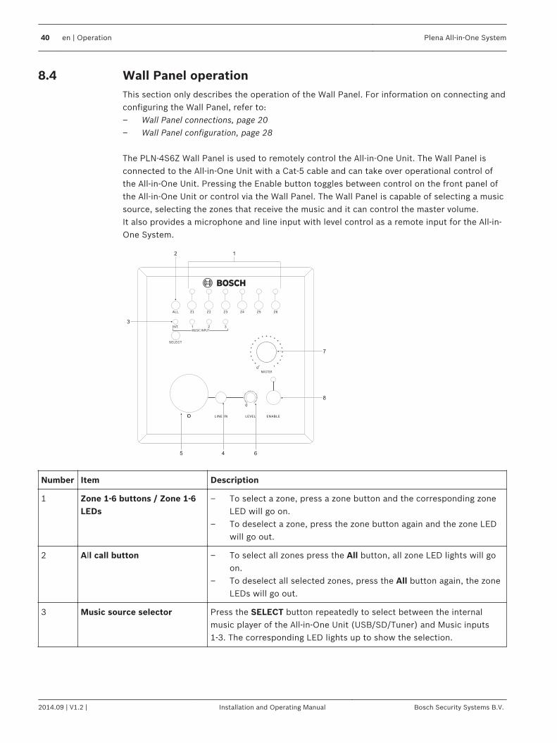
Wall Panel operation This section only describes the operation of the Wall Panel. For information on connecting andconfiguring the Wall Panel, refer to:– Wall Panel connections, page 20– Wall Panel configuration, page 28 The PLN‑4S6Z Wall Panel is used to remotely control the All‑in‑One Unit. The Wall Panel isconnected to the All-in-One Unit with a Cat-5 cable and can take over operational control ofthe All-in-One Unit. Pressing the Enable button toggles between control on the front panel ofthe All-in-One Unit or control via the Wall Panel. The Wall Panel is capable of selecting a musicsource, selecting the zones that receive the music and it can control the master volume.It also provides a microphone and line input with level control as a remote input for the All-in-One System.
12
3
7
8
645
Number Item Description
1 Zone 1-6 buttons / Zone 1-6LEDs
– To select a zone, press a zone button and the corresponding zoneLED will go on.
– To deselect a zone, press the zone button again and the zone LEDwill go out.
2 All call button – To select all zones press the All button, all zone LED lights will goon.
– To deselect all selected zones, press the All button again, the zoneLEDs will go out.
3 Music source selector Press the SELECT button repeatedly to select between the internalmusic player of the All‑in‑One Unit (USB/SD/Tuner) and Music inputs1-3. The corresponding LED lights up to show the selection.
8.4
40 en | Operation Plena All-in-One System
2014.09 | V1.2 | Installation and Operating Manual Bosch Security Systems B.V.

Number Item Description
7 Remote Master volume Use the Remote Master volume control to change the master volumelevel of the All‑in‑One Unit. The remote master volume control is onlyfunctioning when it is enabled on the Wall Panel with the Enable button(7) or when it is enabled by setting the Music selector of theAll‑in‑One Unit (7) to Remote.
8 Enable button – To activate the wall panel, press the Enable button, thecorresponding LED will go on.
– To deactivate the panel, press the Enable button again.– The green Enable LED will flash fast (5 Hz) when a higher priority
signal is active on the All‑in‑One Unit. This can be a signal on theTelephone/Emergency input or from a call station. The Enable LEDwill flash slowly (1 Hz) when it is deactivated.
Plena All-in-One System Operation | en 41
Bosch Security Systems B.V. Installation and Operating Manual 2014.09 | V1.2 |
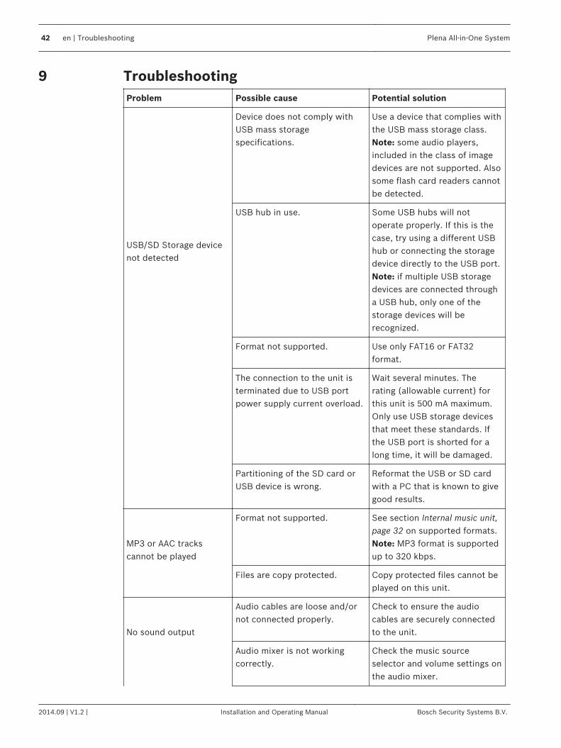
TroubleshootingProblem Possible cause Potential solution
USB/SD Storage devicenot detected
Device does not comply withUSB mass storagespecifications.
Use a device that complies withthe USB mass storage class.Note: some audio players,included in the class of imagedevices are not supported. Alsosome flash card readers cannotbe detected.
USB hub in use. Some USB hubs will notoperate properly. If this is thecase, try using a different USBhub or connecting the storagedevice directly to the USB port.Note: if multiple USB storagedevices are connected througha USB hub, only one of thestorage devices will berecognized.
Format not supported. Use only FAT16 or FAT32format.
The connection to the unit isterminated due to USB portpower supply current overload.
Wait several minutes. Therating (allowable current) forthis unit is 500 mA maximum.Only use USB storage devicesthat meet these standards. Ifthe USB port is shorted for along time, it will be damaged.
Partitioning of the SD card orUSB device is wrong.
Reformat the USB or SD cardwith a PC that is known to givegood results.
MP3 or AAC trackscannot be played
Format not supported. See section Internal music unit,page 32 on supported formats.Note: MP3 format is supportedup to 320 kbps.
Files are copy protected. Copy protected files cannot beplayed on this unit.
No sound output
Audio cables are loose and/ornot connected properly.
Check to ensure the audiocables are securely connectedto the unit.
Audio mixer is not workingcorrectly.
Check the music sourceselector and volume settings onthe audio mixer.
9
42 en | Troubleshooting Plena All-in-One System
2014.09 | V1.2 | Installation and Operating Manual Bosch Security Systems B.V.
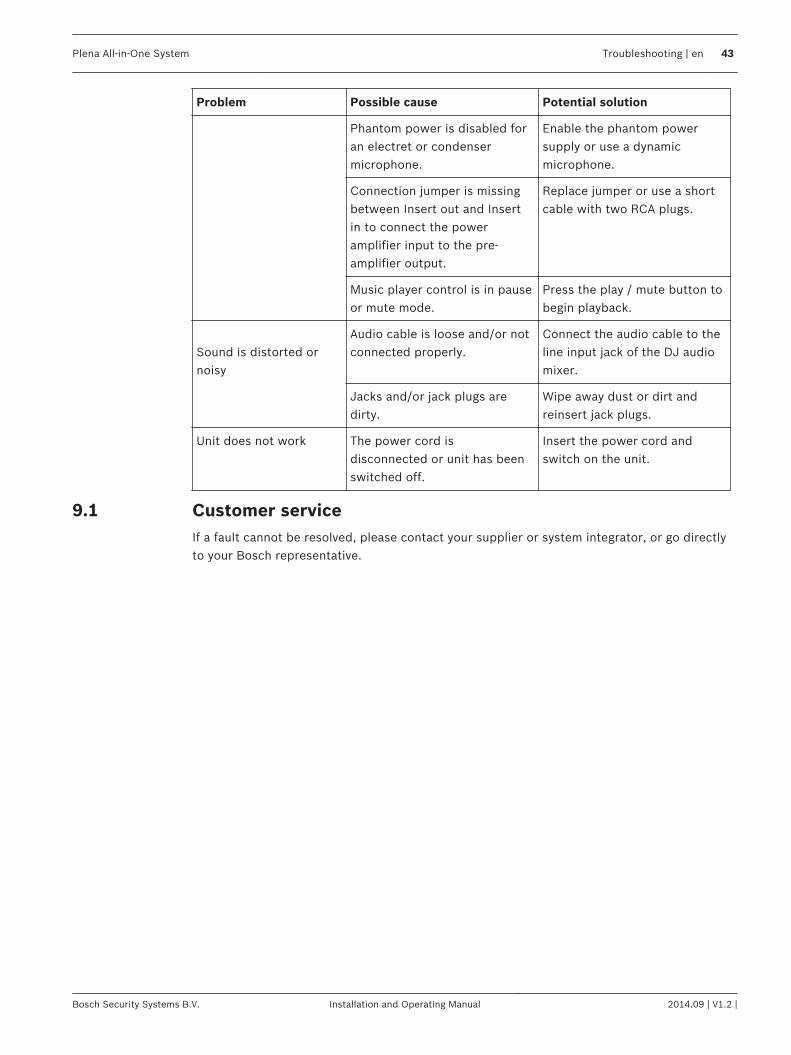
Problem Possible cause Potential solution
Phantom power is disabled foran electret or condensermicrophone.
Enable the phantom powersupply or use a dynamicmicrophone.
Connection jumper is missingbetween Insert out and Insertin to connect the poweramplifier input to the pre-amplifier output.
Replace jumper or use a shortcable with two RCA plugs.
Music player control is in pauseor mute mode.
Press the play / mute button tobegin playback.
Sound is distorted ornoisy
Audio cable is loose and/or notconnected properly.
Connect the audio cable to theline input jack of the DJ audiomixer.
Jacks and/or jack plugs aredirty.
Wipe away dust or dirt andreinsert jack plugs.
Unit does not work The power cord isdisconnected or unit has beenswitched off.
Insert the power cord andswitch on the unit.
Customer serviceIf a fault cannot be resolved, please contact your supplier or system integrator, or go directlyto your Bosch representative.
9.1
Plena All-in-One System Troubleshooting | en 43
Bosch Security Systems B.V. Installation and Operating Manual 2014.09 | V1.2 |
MaintenanceThe units require minimum maintenance, however to keep the units in good condition, thefollowing tasks should be carried out.– Clean the units:
– Periodically clean the units with a damp, lint-free cloth.– Clean the air inlets:
– The units can collect dust from the operation of the internal fans. The air inlets of theunits should therefore be cleaned on a yearly basis.
– Periodically check unit connections and grounding:– To ensure that all cable connections to the units are secure.– The ground (Protective Earth) connection of the system components.
!Warning!
Dangerous mains voltages are present inside the units. Disconnect the main power supply
before doing any maintenance tasks.
10
44 en | Maintenance Plena All-in-One System
2014.09 | V1.2 | Installation and Operating Manual Bosch Security Systems B.V.
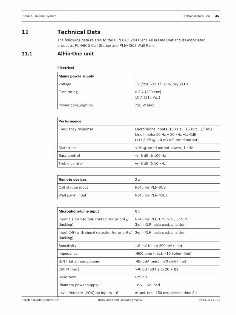
Technical DataThe following data relates to the PLN‑6AIO240 Plena All‑in‑One Unit and its associatedproducts, PLN‑6CS Call Station and PLN‑4S6Z Wall Panel.
All-in-One unit
Electrical
Mains power supply
Voltage 115/230 Vac +/- 15%, 50/60 Hz
Fuse rating 6.3 A (230 Vac)10 A (115 Vac)
Power consumption 720 W max
Performance
Frequency response Microphone inputs: 100 Hz – 15 kHz +1/-3dBLine inputs: 50 Hz – 20 kHz +1/-3dB(+1/‑3 dB @ ‑10 dB ref. rated output)
Distortion <1% @ rated output power, 1 kHz
Bass control +/- 8 dB @ 100 Hz
Treble control +/- 8 dB @ 10 kHz
Remote devices 2 x
Call station input RJ45 for PLN‑6CS
Wall panel input RJ45 for PLN‑4S6Z
Microphone/Line input 6 x
Input 1 (Push-to-talk contact for priority/ducking)
RJ45 for PLE‑1CS or PLE‑1SCS3‑pin XLR, balanced, phantom
Input 2-6 (with signal detector for priority/ducking)
3‑pin XLR, balanced, phantom
Sensitivity 1.5 mV (mic); 200 mV (line)
Impedance >600 ohm (mic); >10 kohm (line)
S/N (flat at max volume) >65 dBA (mic); >70 dBA (line)
CMRR (mic) >40 dB (50 Hz to 20 kHz)
Headroom >25 dB
Phantom power supply 18 V – No load
Level detector (VOX) on Inputs 1-6 Attack time 150 ms; release time 3 s
11
11.1
Plena All-in-One System Technical Data | en 45
Bosch Security Systems B.V. Installation and Operating Manual 2014.09 | V1.2 |
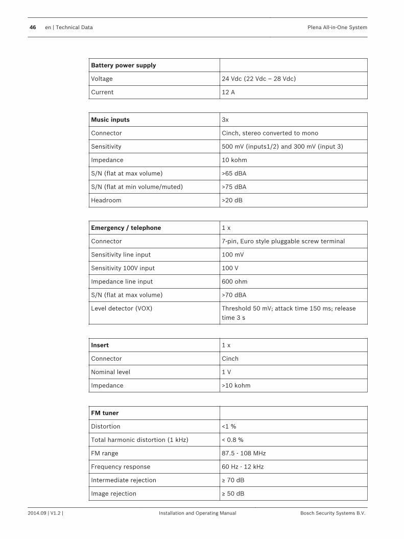
Battery power supply
Voltage 24 Vdc (22 Vdc – 28 Vdc)
Current 12 A
Music inputs 3x
Connector Cinch, stereo converted to mono
Sensitivity 500 mV (inputs1/2) and 300 mV (input 3)
Impedance 10 kohm
S/N (flat at max volume) >65 dBA
S/N (flat at min volume/muted) >75 dBA
Headroom >20 dB
Emergency / telephone 1 x
Connector 7‑pin, Euro style pluggable screw terminal
Sensitivity line input 100 mV
Sensitivity 100V input 100 V
Impedance line input 600 ohm
S/N (flat at max volume) >70 dBA
Level detector (VOX) Threshold 50 mV; attack time 150 ms; releasetime 3 s
Insert 1 x
Connector Cinch
Nominal level 1 V
Impedance >10 kohm
FM tuner
Distortion <1 %
Total harmonic distortion (1 kHz) < 0.8 %
FM range 87.5 - 108 MHz
Frequency response 60 Hz - 12 kHz
Intermediate rejection ≥ 70 dB
Image rejection ≥ 50 dB
46 en | Technical Data Plena All-in-One System
2014.09 | V1.2 | Installation and Operating Manual Bosch Security Systems B.V.
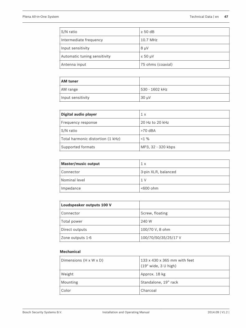
S/N ratio ≥ 50 dB
Intermediate frequency 10.7 MHz
Input sensitivity 8 μV
Automatic tuning sensitivity ≤ 50 μV
Antenna input 75 ohms (coaxial)
AM tuner
AM range 530 - 1602 kHz
Input sensitivity 30 μV
Digital audio player 1 x
Frequency response 20 Hz to 20 kHz
S/N ratio >70 dBA
Total harmonic distortion (1 kHz) <1 %
Supported formats MP3, 32 - 320 kbps
Master/music output 1 x
Connector 3‑pin XLR, balanced
Nominal level 1 V
Impedance <600 ohm
Loudspeaker outputs 100 V
Connector Screw, floating
Total power 240 W
Direct outputs 100/70 V, 8 ohm
Zone outputs 1-6 100/70/50/35/25/17 V
Mechanical
Dimensions (H x W x D) 133 x 430 x 365 mm with feet(19" wide, 3 U high)
Weight Approx. 18 kg
Mounting Standalone, 19” rack
Color Charcoal
Plena All-in-One System Technical Data | en 47
Bosch Security Systems B.V. Installation and Operating Manual 2014.09 | V1.2 |

Environmental
Operating temperature -10 ºC to +45 ºC (14 ºF to +113 ºF)
Storage temperature -40 ºC to +70 ºC (-40 ºF to +158 ºF)
Relative humidity <95% (non‑condensing)
Generic performance specifications
Acoustic noise < 45 dB SPL, measured at 1 meter above theunit
MTBF 1200000 hours at 25°C
48 en | Technical Data Plena All-in-One System
2014.09 | V1.2 | Installation and Operating Manual Bosch Security Systems B.V.
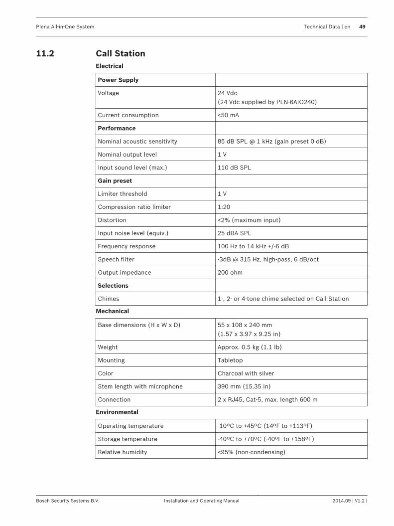
Call StationElectrical
Power Supply
Voltage 24 Vdc(24 Vdc supplied by PLN‑6AIO240)
Current consumption <50 mA
Performance
Nominal acoustic sensitivity 85 dB SPL @ 1 kHz (gain preset 0 dB)
Nominal output level 1 V
Input sound level (max.) 110 dB SPL
Gain preset
Limiter threshold 1 V
Compression ratio limiter 1:20
Distortion <2% (maximum input)
Input noise level (equiv.) 25 dBA SPL
Frequency response 100 Hz to 14 kHz +/-6 dB
Speech filter -3dB @ 315 Hz, high-pass, 6 dB/oct
Output impedance 200 ohm
Selections
Chimes 1-, 2- or 4-tone chime selected on Call Station
Mechanical
Base dimensions (H x W x D) 55 x 108 x 240 mm(1.57 x 3.97 x 9.25 in)
Weight Approx. 0.5 kg (1.1 lb)
Mounting Tabletop
Color Charcoal with silver
Stem length with microphone 390 mm (15.35 in)
Connection 2 x RJ45, Cat‑5, max. length 600 m
Environmental
Operating temperature -10ºC to +45ºC (14ºF to +113ºF)
Storage temperature -40ºC to +70ºC (-40ºF to +158ºF)
Relative humidity <95% (non‑condensing)
11.2
Plena All-in-One System Technical Data | en 49
Bosch Security Systems B.V. Installation and Operating Manual 2014.09 | V1.2 |
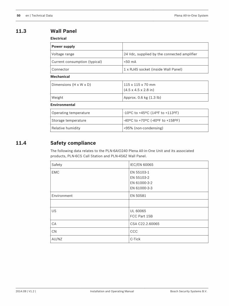
Wall PanelElectrical
Power supply
Voltage range 24 Vdc, supplied by the connected amplifier
Current consumption (typical) <50 mA
Connector 1 x RJ45 socket (inside Wall Panel)
Mechanical
Dimensions (H x W x D) 115 x 115 x 70 mm(4.5 x 4.5 x 2.8 in)
Weight Approx. 0.6 kg (1.3 lb)
Environmental
Operating temperature -10ºC to +45ºC (14ºF to +113ºF)
Storage temperature -40ºC to +70ºC (-40ºF to +158ºF)
Relative humidity <95% (non‑condensing)
Safety complianceThe following data relates to the PLN‑6AIO240 Plena All‑in‑One Unit and its associatedproducts, PLN‑6CS Call Station and PLN‑4S6Z Wall Panel.
Safety IEC/EN 60065
EMC EN 55103-1EN 55103-2EN 61000-3-2EN 61000-3-3
Environment EN 50581
US UL 60065FCC Part 15B
CA CSA C22.2.60065
CN CCC
AU/NZ C-Tick
11.3
11.4
50 en | Technical Data Plena All-in-One System
2014.09 | V1.2 | Installation and Operating Manual Bosch Security Systems B.V.

Bosch Security Systems B.V.Torenallee 495617 BA EindhovenThe Netherlandswww.boschsecurity.com© Bosch Security Systems B.V., 2014