platform - smartmeye.com · 5 1.products 1.1. summary cmsvision isalarge-scale network monitoring...
TRANSCRIPT
3
CentralizedCentralizedCentralizedCentralized MonitoringMonitoringMonitoringMonitoring ManagementManagementManagementManagementPlatformPlatformPlatformPlatform
MMMManualanualanualanual
4
ContentsContentsContentsContents
1.1.1.1. ProductsProductsProductsProducts................................................................................................................................................................................................................................................................................................................................................................55551.1. Summary.................................................................................................................... 51.2. Application Environment...............................................................................................51.3. Install and uninstall...................................................................................................... 6
2.2.2.2. CentralizedCentralizedCentralizedCentralized MonitoringMonitoringMonitoringMonitoring ManagementManagementManagementManagement PlatformPlatformPlatformPlatform HelpHelpHelpHelp................................ 66662.1. Software start...............................................................................................................62.2. Login and Logoff System.............................................................................................. 62.3. Add Device................................................................................................................. 72.4.Main Interface Instruction.............................................................................................. 9
2.4.1.Image preview operation..............................................................................112.4.2 Screen switch............................................................................................. 132.4.3.Context menu............................................................................................. 13
2.5. Remote operation PTZ................................................................................................ 142.6. Image Management.................................................................................................... 152.7. System Setup............................................................................................................. 16
2.7.1 System Setup............................................................................................. 162.7.2. Remote configuration................................................................................. 172.7.3. Remote Login settings................................................................................ 262.7.4. Electronic Map.......................................................................................... 272.7.5.Alarm relate setting.....................................................................................292.7.6. Alarm out..................................................................................................33
2.8. Recording Features..................................................................................................... 332.8.1. Open and close the video............................................................................ 332.8.2. Remote playback....................................................................................... 352.8.3. Local playback.......................................................................................... 372.8.4. Record schedule........................................................................................ 382.8.5. Set collective record................................................................................... 402.8.6. Switch video file by force........................................................................... 41
2.9. Advanced.................................................................................................................. 432.9.1. Video group setup...................................................................................... 432.9.2. Video group switch.................................................................................... 442.9.3. Video cruise.............................................................................................. 442.9.4. TVWall.................................................................................................... 442.9.5. Voice intercom...........................................................................................462.9.6. View log................................................................................................... 502.9.7. See picture................................................................................................ 51

5
1.1.1.1. ProductsProductsProductsProducts
1.1.1.1.1.1.1.1. SummarySummarySummarySummary
CMSVision is a large-scale network monitoring and management software, distributed networktopology, and support for streaming media transmitted directly connected to the network serverfront-end Video Capture:1, and highly scalable, according to customer demands to expand their control, a control point is acentralized monitoring and management platform.2, in the user access control, streaming media transmitted adoption of a unified user access control,streaming media server user permissions check, directly connecting the server front-end videocapture, video capture server-tested for competence.3, focus on monitoring and management platform supports multi-screen images and previewimages as round, as well as electronic map image preview and joint operation of the policefunction.4, in the network to adopt the most advanced technology to complete port in the same networkenvironment than the general quality of the TCP network transmission more efficient, but alsosupport the break-even.5, support on the market today mainstream board and the mainstream DVR-embedded DVR orDVS.6, front-end support remote video capture server configuration, remote video capture playbackfront of a video file servers, remote-control video capture front-end server Haeundae or otherrelated equipment.7, regular support, as well as video and manual on the server front-end video capture video onmobile alarm linked in a document on video playback, the manner and time of the progress ofsearch and playback in the process of positioning can be arbitrary time intervals operationarbitrary state support Quick Search simultaneously positioning, support cycle broadcast, videoediting documents, local amplification and video files can be damaged due to brownout andautomatic restoration capabilities.8, TV wall function.9, centralized monitoring and management platform in the front-end server records the alarm log,for real-time alarm log.10, or between management platform to support management platform and front-end serversVideo Capture speaking voice and voice broadcasting.
1.2.1.2.1.2.1.2. ApplicationApplicationApplicationApplication EnvironmentEnvironmentEnvironmentEnvironment
The configuration of the system requirements are as follows:Hardware

6
CPU:P41.7GHz and aboveMemory:256MB and aboveGraphics:Geforce 4 64MB and aboveSoftwareOS:Windows2000、Windows XP、windows2003DX:DirectX8.1 and aboveDisk SpaceIn order to ensure the normal operation of video, hard disk free space may not be less than 80 G.
1.3.1.3.1.3.1.3. InstallInstallInstallInstall andandandand uninstalluninstalluninstalluninstall
Install and uninstall very simple installation package is a self-extracting file, double-click themouse directly install icon will be notified by the successful installation. Uninstall program in theStart menu, the selection "Program" -> "Centralized Monitoring Management Platform" ->"Uninstall", will be able to swap unloading procedures.
2.2.2.2. CentralizedCentralizedCentralizedCentralized MonitoringMonitoringMonitoringMonitoring ManagementManagementManagementManagement
PlatformPlatformPlatformPlatform HelpHelpHelpHelp
2.1.2.1.2.1.2.1. SoftwareSoftwareSoftwareSoftware startstartstartstart
Direct operations in the installation directory under "CMS.exe" document will be launchedon monitoring and management platform, or double-clicked desktop shortcut "CMS".
2.2.2.2.2.2.2.2. LoginLoginLoginLogin andandandand LogoffLogoffLogoffLogoff SystemSystemSystemSystem
In the login dialog box, enter the administrator user name (the default is: system) and password,click on the OK button to start the system.

7
Click the button " " in the upper right corner of the main interface,Can pop-up confirmation
to exit the dialog box, click "Login" to exit.
。
Click the button "Exit" in the lower right corner, the pop-up "ExitSystem" dialog box, then click "Yes" button to exit.
2.3.2.3.2.3.2.3. AddAddAddAdd DeviceDeviceDeviceDevice
Device type: D/N/I 2013,DVR 2012,DVR 2011,DVR 2010 etc. D/N/I 2013(D means DVR, Nmeans NVR, I means IPC) can automatically be searched and added.:
Enter the main interface, click on the device list area; or go to
menu->System Setup->Device Management, then click , then you will
see the pop-up Device Management dialog box, then click in the pop-up box to add device.
Please check the following picture:

8
Or you can add the device by clicking . Type P2P ID in the host name, and 0 in
the port, then it can connect by P2P. Please check the below picture:
PleasePleasePleasePlease note:note:note:note:you must choose the corresponding type in host type, self-define the description,
type the IP address, domain or P2P ID in host name or IP, and write CMD port of device or 0 if byP2P. The user name and the password are the same as that of the device.

9
2.4.Main2.4.Main2.4.Main2.4.Main InterfaceInterfaceInterfaceInterface InstructionInstructionInstructionInstruction
At the right of the main interface is the main menu area (ie. Control Panel area).At the center of the main interface is the Real-time monitoring area.At the left of the main interface is Device List area.At the lower part is real-time alarm information display area.Between the Real-time monitoring area and the real-time alarm information display area is theSplit-screen display area.
Menu StructureNo. First-level
menuSecond-levelmenu
Third-level menu
Function introduction
1 preview Click the corresponding button to select previewmode. Tour the preview channels, switch amongchannels or snapshot live picture.Close / open livepreview.

10
2 PTZ Move the PTZ toward up, down, right, left by thecontrol panel; adjust the step,zoom,focus,iris of PTZ;set the preset and cruise path; when turn on the cruisefunction, the PTZ will move according the presetcruise path.
3 Imagemanagement
Set brightness, contrast, saturation, hue
4 Systemsetup
Local setup Systemsetup
Select video storage, video streams; setup start-up OSand pack record.
Usermanagement
Add, delete, and manage the users; setup user name,password and authority
Remoteconfig
Deviceconfig
Setup the device configuration in remote, and keep thesetup in local DVR.
Devicemanagement
AdddeviceRevisedeviceDeletedevice
Add device; revise the host name, host IP, the username and password; and delete device
E-map Pop-upE-map
Users can add or delete cameras in the simulate mapand setup E-map alarm.
AlarmrelateE-map
If an alarm event occurs, and the alarm points havebeen added to the E-map, the map will pop up andflash the corresponding alarm device icon,double-click the icon to open the corresponding video.
Alarm relatesetup
Task Alarm relate enlarge the window and start recordingschedule The schedule setup of the alarm relate
Alarm outputdevice
Shortmessage
Need buy the message module device to send messagewhile alarm
Close alarmsound
Turn on/off the alarm sound
5 Recording features
Start record Select the corresponding channels or devices to startrecording
Stop record Select the corresponding channels or devices to stoprecording
Remoteplayback
Search the recording files from the remote device
Localplayback
Search the recording files saved in the computer
Recordingschedule
Set the recording time in the CMS

11
Set collectiverecord
Set different DVR to record collectively
Switch videofile
If the pack record time is 1 hour, and you need backupor check the recording files that is unpacked, then youcan switch video files.
6 advanced Group setup Combine or group any channels for cruise or groupswitch
Switch group switch the self-defined video groupVideo cruise Set in group setup and automatically switch among the
selected groupsTVwall Additional option,under developmentVoiceintercom
The voice intercom among CMS
View log Search alarm,login, system operation, network loginformation
See picture Check the snapshot picturehelp Users’ manual
2.4.1.Image2.4.1.Image2.4.1.Image2.4.1.Image previewpreviewpreviewpreview operationoperationoperationoperation
Right-Click on the device or any camera of the device in the Device List area, then select "OpenSub-stream" or "Open Main stream" menu, can realize the image preview function.

12
There are three ways to open Preview:1. Right-click menu "Open Preview."2. Rejection node to drag the video window on the left.3. Access nodes in the double-click.
More than four menu items are selected based on the current node for the operation of the image,if selected node is the host, is that the main frame operating below all channels, if the selectedchannel is only the current channel operation If selected is the streaming media server, it is notgray with the state.

13
2.4.22.4.22.4.22.4.2 ScreenScreenScreenScreen switchswitchswitchswitch
The area between video display area and alarm information display area is the screen switch area.
Click the left mouse button on the icon , can switch more split screen number.
Choose a different split screen button can be switched screen number. "Page up" and "Page down"page and "Full screen"-provided function. (Hint: PageUp and PageDown can turn the pages)
Click the button can start all preview. stop all preview. start all
record. stop all record.
2.4.3.C2.4.3.C2.4.3.C2.4.3.Contextontextontextontext menumenumenumenu
In the video display area, you can do the following operations by right-click the mouse:
Close preview: close the video of the current channelClose all preview: close the video of all the channelsVoice monitoring: to hear the voice from the live preview

14
Snapshot: snapshot the picture, and save in the computer. If the pictures are saved in the defaultfolder, then you can check the pictures by going to menu->advanced->see pictureFull screen: full screenDigital zoom: to zoom any area of video
2.5.2.5.2.5.2.5. RemoteRemoteRemoteRemote operationoperationoperationoperation PTZPTZPTZPTZ
Image window is selected as the current window, if the current window configurations are PTZ,the button was available state:
Click the completion of the operation of the same action. Then click of a button
the pop-up dialog box, calling the corresponding preset points.

15
2.6.2.6.2.6.2.6. ImageImageImageImage ManagementManagementManagementManagement
Image window is selected as the current window, point operation "ImageManagement" button
or scroll bar can adjust image brightness and color, image and voice
volume can be adjusted.
Note:

16
Click the "Default" button , all the configuration about image management will restore the
default.
Click the "All same" button , all of the other channels will be set to the same image
display status as the current selected channel.
2.7.2.7.2.7.2.7. SystemSystemSystemSystem SetupSetupSetupSetup
2.7.12.7.12.7.12.7.1 SystemSystemSystemSystemSetupSetupSetupSetup
Go to menu->system setup->local setup, and pop-up the below window:
System setup: setup the system according to your habits or requirementsPlease note: the system select main stream by default. If you select sub-stream, please restart thesoftware.User management:

17
In the users management window, please click to add user, to revise the password,
to delete users. The right is the authority that user could have. Only the advanced admin can
assign the authority to the new users.
2.7.2.2.7.2.2.7.2.2.7.2. RemoteRemoteRemoteRemote configurationconfigurationconfigurationconfiguration
In the "Device List" area to select a DVR, right-click, pop-up menu, select "Remote Config"menuOr in the "Device List" area to select a DVR, then in the main menu, select the "System
Setup"->"Remote config", click of a button , if it is embedded DVR or pop-up
on the corresponding DVS brand Embedded Remote Configuration dialog.

18
To configure and control the device by client software, select remote config and the device fromthe devices list.A, system configuration. Set the basic information of device and update the device in remote.Please check the below picture:

19
B, network setup. Set IP, DNS and so on. Please check the detailed as below
picture:

20
C, network service.set device to visit it by WAN and to send email.Please check the below picture:
D, channel setup. Set the resolution, frame rate, bit rate and change the channel name.please check

21
the details as the below picture:
E, record setup. Set the record time, record type. Please check the below picture:

22
F, alarm setup. Set alarm relate when the corresponding alarm( motion detection, video lost, alarm
input) is triggered. Please check the below picture:

23
G, PTZ setup. Set the PTZ configuration to control PTZ. Please check the below picture:
H, user setup. Add, delete, revise users and set the authority of the users. Please check the below

24
picture:
I, log. Search system log and alarm log. Set the date and click search, then you will see the below
picture:

25
J, device info. Check the record channels, system version and other information. Please check the
below picture.

26
2.7.3.2.7.3.2.7.3.2.7.3. RemoteRemoteRemoteRemote LoginLoginLoginLogin settingssettingssettingssettings
27
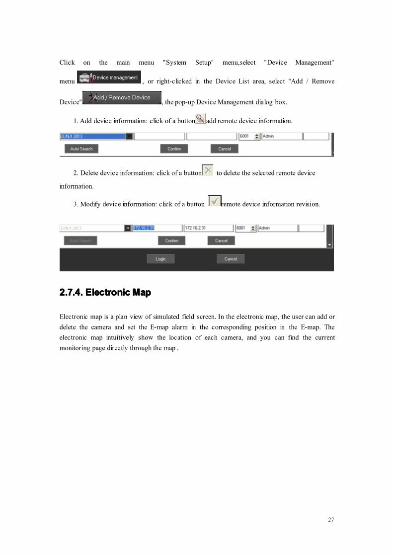
Click on the main menu "System Setup" menu,select "Device Management"
menu , or right-clicked in the Device List area, select "Add / Remove
Device" , the pop-up Device Management dialog box.
1. Add device information: click of a button add remote device information.
2. Delete device information: click of a button to delete the selected remote device
information.
3. Modify device information: click of a button remote device information revision.
2.7.4.2.7.4.2.7.4.2.7.4. ElectronicElectronicElectronicElectronic MapMapMapMap
Electronic map is a plan view of simulated field screen. In the electronic map, the user can add ordelete the camera and set the E-map alarm in the corresponding position in the E-map. Theelectronic map intuitively show the location of each camera, and you can find the currentmonitoring page directly through the map .

28
Click on the main menu to the "System Setup", then to the "E-map" menu ,
choose "pop-up electronic map" menu , can be hidden or
pop-up electronic map.
1、 Installation of electronic map: click of a button , the pop-up menu
configuration organizations can add, modify, delete organizational layers.
2、Delete electronic equipment map: click of a button to delete the selected mapicon equipment.
3、 The preservation of electronic map: click of a button preserve electronic
maps installed.
4、Withdraw from the electronic map: click of a button hidden electronic map.
5、Add electronic map equipment: Conventional operating area of the left side of thecamera icon dragged on the map, the camera can be added to the

29
map.
6、 Electronic maps equipment operators: Double-click electronic camera icon on the map,to open the camera image.
7、Electronic alarm linkage map: in the electronic map of the
election or switching to an electronic map shows that, if the server front-end video acquisitionoccurred alarm, and the police point has been added to the electronic map, the map will pop upand flashing icon corresponding alarm equipment , double-click the icon to open thecorresponding video.

30
2.7.5.Alarm2.7.5.Alarm2.7.5.Alarm2.7.5.Alarm relaterelaterelaterelate settingsettingsettingsetting
Click on the main menu "System Setup", select "Alarm relate setup" menu , the
pop-up "Alarm relate setup" dialog.。
1、 cameras channel alarm linkage: Video Capture selected a server, right click, pop-upmenu, choose "channel relate," the camera can be given for each video channel automaticalarm correlation can also manually set up video linkage, as long as check linkagechannel video camera on the trip.
2、 Set up joint police sensor: a video capture selected server, right click, pop-up menu,select "sensor related", each probe can be automatically linked to the police video (suchas: "sensor 1" connection "Camera 1" video), can also be manually set up joint video, aslong as the check linkage channel video camera on the trip.
3、 Linkage video settings: Laws can be numerical.
4、 Copied to the other server: click of a button , the pop-up "copy to…" dialog
box, check the server, click can be identified will be set up replication to other servers.5、 Save Settings: Setting up good, click can be identified.

31
6, Click the above “schedule”, then you can make alarm relate recording schedule accordingto your time.

32
The button can make the current day’s setting copy to all the other days of a
week.
The button can delete the current selected time section.
The button can delete the current selected day’s time section.
The button can empty all the sections of a week
The button can accurately set the time to seconds.
Click the button : Add Time section, enter into the precise position time interface as follows.
The button : Update Time section.
The button : Delete Time section.

33
2.7.6.2.7.6.2.7.6.2.7.6. AlarmAlarmAlarmAlarmoutoutoutout
Go to main menu->system setup->alarm output device, or click , then itpop-up the window.
This is not enable by default. You can enable and write the serial port, bit
rate, alarm service center phone number, mobile phone number. After setup, just click “confirm”
2.8.2.8.2.8.2.8. RecordingRecordingRecordingRecording FeaturesFeaturesFeaturesFeatures
2.8.1.2.8.1.2.8.1.2.8.1. OpenOpenOpenOpen andandandand closeclosecloseclose thethethethe videovideovideovideo
In the "Device List" area, click the right mouse button, the pop-up menu, select "Start record"
menu launched on recording video, select "Stop record" menu stop
recording. If you choose the server, the server started all channel record, if you select the cameraaccess, video channel started.

34
2.In the equipment list, equipment or channel nodes, right-click menu, choose "start video", can
also open the local video.

35
All the menu items above are based on the currently selected node for the operation of, if theselected node is host, all is operating under the corresponding host channel, if the selected channelis the only current channel operation, if the selected is streaming media server, is a state of gray is
not available。
2.8.2.2.8.2.2.8.2.2.8.2. RemoteRemoteRemoteRemote playbackplaybackplaybackplayback
In the "Device List" area, select a DVR, right-click, pop-up menu, select "Remote playback" menu
or click of a button , if it is embedded DVR or DVS
Embedded Remote playback on the pop-up interface, Embedded Remote playback supporting upto one screen , four screen ,nine screen ,sixteen screen playback, each frame of a camera
corresponding channel.
36
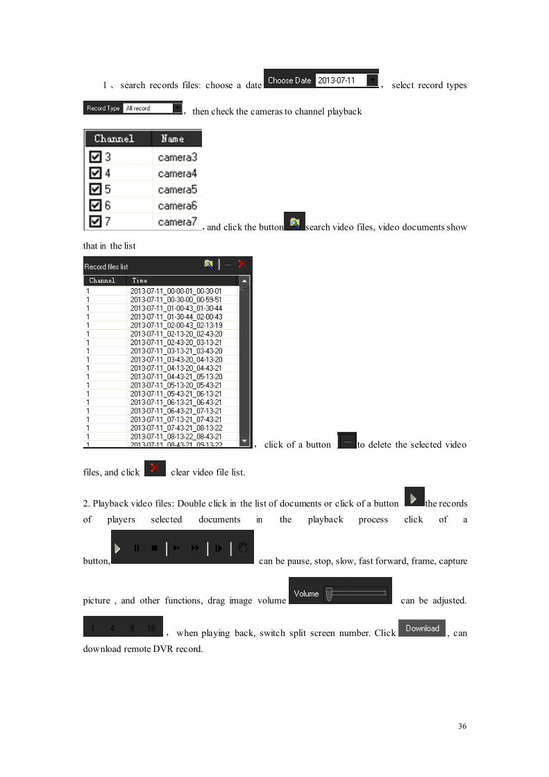
1、 search records files: choose a date , select record types
,then check the cameras to channel playback
,and click the button search video files, video documents show
that in the list
, click of a button to delete the selected video
files, and click clear video file list.
2. Playback video files: Double click in the list of documents or click of a button the records
of players selected documents in the playback process click of a
button, can be pause, stop, slow, fast forward, frame, capture
picture , and other functions, drag image volume can be adjusted.
,when playing back, switch split screen number. Click , can
download remote DVR record.
37
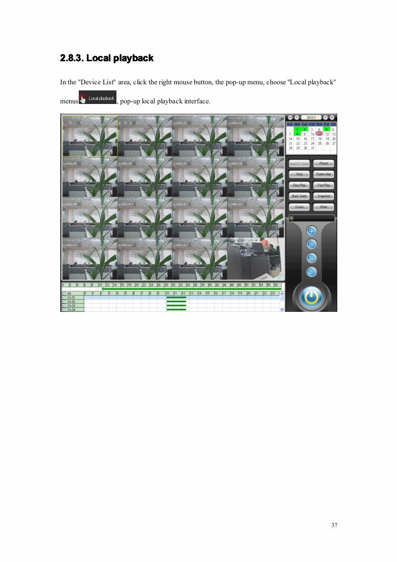
2.8.3.2.8.3.2.8.3.2.8.3. LocalLocalLocalLocal playbackplaybackplaybackplayback
In the "Device List" area, click the right mouse button, the pop-up menu, choose "Local playback"
menus , pop-up local playback interface.

38
2.8.4.2.8.4.2.8.4.2.8.4. RecordRecordRecordRecord scheduleschedulescheduleschedule
The button can set continuous recording all the week.
The button can make the current day’s setting copy to all the other days of a
week.
The button can delete the current selected time section.
The button can delete the current selected day’s time section.
The button can empty all the sections of a week
The button can accurately set the time to seconds.

39
Click the button : Add Time section, enter into the precise position time interface as follows.
The button : Update Time section.
The button : Delete Time section.
If any other channels are the same recording time setting as the current channel, just need to
click the button "Copy to…" below the channel list, the pop-up dialog
box.
button "Copy to…" below the host list, the pop-up dialog box.

40
2.8.5.2.8.5.2.8.5.2.8.5. SetSetSetSet collectivecollectivecollectivecollective recordrecordrecordrecord
SetSetSetSet collectivecollectivecollectivecollective recordrecordrecordrecord
Click theMain menu ->"Recording Features" ->"Set collective record" , the
pop-up "Set collective record" dialog box.
Select the host or some camera under host list, then directly drag to the left Camera list area. ClickConfirm button. It needs to manually restart the software, the setting take effect.Setting collect record function is used among the different channels of the multiple DVR tocollect record and replay.

41
2.8.6.2.8.6.2.8.6.2.8.6. SwitchSwitchSwitchSwitch videovideovideovideo filefilefilefile bybybyby forceforceforceforce
Click on the main menu "Recording Features", select "Forced to switch video file" menu
, the pop-up following confirm dialog box.
Click confirm button, all the recording video files will be packaged and then can be immediatelyreplayed, although in the Local setup->System Setup, the Record time is 60 min. that is to sayevery 60 minutes, there will be one package in the Video Store area of the PC.

42
43
2.9.2.9.2.9.2.9. AdvancedAdvancedAdvancedAdvanced
2.9.1.2.9.1.2.9.1.2.9.1. VideoVideoVideoVideo groupgroupgroupgroup setupsetupsetupsetup
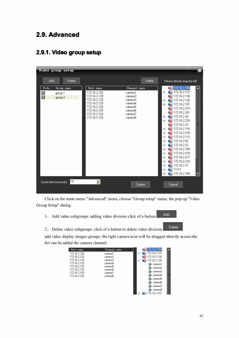
Click on the main menu "Advanced" menu, choose "Group setup" menu, the pop-up "VideoGroup Setup" dialog.
1、Add video subgroups: adding video division click of a button.
2、Delete video subgroups: click of a button to delete video division.
add video display images groups: the right camera icon will be dragged directly access thelist can be added the camera channel.

44
3、Video settings as packet round: Amending the lower part of the
value , depending on time round can be set up, check
the video to determine which groups will enter the round as group.
2.9.2.2.9.2.2.9.2.2.9.2. VideoVideoVideoVideo groupgroupgroupgroup switchswitchswitchswitch
After setting multiple groups, multiple groups can be manually switched as follows:
Select one group, then all the channels of the group will open preview in the Real-time monitoringarea.
2.9.3.2.9.3.2.9.3.2.9.3. VideoVideoVideoVideo cruisecruisecruisecruise
Click "Video cruise" button in the main menu "Advanced", then all the groups will poll and switchaccording to the cruise time. Every 15 seconds, the group will be switched to display, if set as
follows.
2.9.4.2.9.4.2.9.4.2.9.4. TVTVTVTVWallWallWallWall
Click on Main Menu "Advanced" ->"TV wall", select "TV wall setup" menu, the pop-up "TVwall Output Settings" dialog.Note:Note:Note:Note: DecoderDecoderDecoderDecoder cardcardcardcard mustmustmustmust bebebebe installedinstalledinstalledinstalled orororor TVTVTVTVwallwallwallwall setupsetupsetupsetup isisisis disabled.disabled.disabled.disabled.

45
1. TVwall set up sub-groups: the click of a button , add TV output wall grouped under
the group name below actual output channel matrix card number automatically
generated output channel list, the click of a button to delete the selected output
sub-click of a button Laws selected output division title. Below is the output of
each division wall TV output channel, a corresponding output channel.2. Television set output wall display images: the left side of the camera will be dragged
directly on the camera can be selected for the television display output channel addedoutput images. According to the output of each channel of the camera, and automaticsegmentation images. The following chart output channel 1 added four camera images,when output to a television, the whole TV screen will be automatically divided into fourimages, showed that four camera images.

46
3. Polling wall television set output: the lower part of the revised
value can be set by polling group output to the TV
wall interval.4. TV wall output operation: the main menu click on the "TV wall", select "Round robin
output" or "Manual output" menu, can be achieved by grouping polling output to a TVwall or manually select group output to a TV wall.
5. If you do not want to continue to export images to TV wall at the main menu can "TVwalls", select "Close output."
2.9.5.2.9.5.2.9.5.2.9.5. VoiceVoiceVoiceVoice intercomintercomintercomintercom
2.9.5.12.9.5.12.9.5.12.9.5.1 VoiceVoiceVoiceVoice intercomintercomintercomintercom (between(between(between(between CMSCMSCMSCMS andandandand DVR)DVR)DVR)DVR)
In the Device List area, right-clicked one device,select “Voice intercom”, the pop-up Network

47
intercom dialog box as follows.
Click the “Start intercom” button to start chat.
Click the “Stop intercom” button to stop chat.

48
2.9.5.22.9.5.22.9.5.22.9.5.2 VoiceVoiceVoiceVoice intercomintercomintercomintercom (between(between(between(between CMSCMSCMSCMS andandandand CMS)CMS)CMS)CMS)
Go to main menu->advanced->voice intercom, then it pop-up the window.1, set the host:
A, add the host:
First input the IP or domain of the host, then click , then the host is added
B, delete host:
Select a host, then click .
C, after enable , CMS directly start voice intercom without the pop-up
request.2, control voice intercom:
Select a host, then click to start voice intercom.
Click to stop voice intercom.

49
2.9.5.32.9.5.32.9.5.32.9.5.3 voicevoicevoicevoice broadcastbroadcastbroadcastbroadcast (between(between(between(between CMSCMSCMSCMSandandandand CMSCMSCMSCMS))))
Go to main menu-> advanced-> voice intercom, then click in the pop-up window.
1, set broadcast target host. The same way as the voice intercom, and you can not set targethost while broadcasting.
2, control broadcast:
Select a target host, then click to start broadcast.
Click to stop broadcast.

50
2.9.6.2.9.6.2.9.6.2.9.6. ViewViewViewView loglogloglog
Click on the main menu "Advanced", select "View log" menu , the pop-up "Log
management" dialog box.

51
2.9.7.2.9.7.2.9.7.2.9.7. SeeSeeSeeSee picturepicturepicturepicture
Click on the main menu "Advanced", select "See picture" menu , the pop-up plug dialog box.Note: only can see the picture in the default snapshot path.