{plate heat exchanger design software for industrial and ......plate heat exchanger is a type of...
TRANSCRIPT
439
Plate heat exchanger design software for industrial and educational applications Nikola R. Zlatković, Divna M. Majstorović, Mirjana Lj. Kijevčanin, Emila M. Živković Faculty of Technology and Metallurgy, University of Belgrade, Belgrade, Serbia
Abstract Plate heat exchanger is a type of heat exchanger that uses corrugated metal plates to transfer heat between two fluids. The plate corrugations are designed to achieve turbul-ence across the entire heat transfer area thus producing the highest possible heat transfer coefficients while allowing close temperature approaches. Subsequently, this leads to asmaller heat transfer area, smaller units and in some cases, fewer heat exchangers. In this work, an application for thermal and hydraulic computations of plate heat exchangers had been developed using Sharp Develop, an open source programming platform. During thedevelopment process, several literature methods and correlations for calculation of heattransfer coefficient and pressure drop in a plate heat exchanger have been tested and the selected four methods: Martin, VDI, Kumar and Coulson and Richardson have beenincorporated into the software. The structure of the software is visually presented throughseveral windows: a window for inserting input data, windows for showing the results of computation by each of the methods, a window for showing comparative analysis of themost important computation results obtained by all of the used methods and a help win-dow for demonstrating the working principle of plate heat exchanger.
Keywords: plate heat exchanger, heat transfer, pressure drop, software.
TECHNICAL PAPER
UDC 004.4:620.1:66:536.2
Hem. Ind. 71 (5) 439–449 (2017)
Available online at the Journal website: http://www.ache.org.rs/HI/
The transfer of heat to and from process fluids is an essential part of most chemical processes. Heat exchanger is a heat transfer device that transfers heat between two or more process fluids. One of the most commonly used types of heat exchangers is a plate heat exchanger (PHE).
Plate heat exchangers are widely used in dairy and food processing plants, chemical industries, power plants and central cooling systems. They exhibit excel-lent heat transfer characteristics, which allows a very compact design, and can easily be disassembled for maintenance, cleaning or for modifying the heat trans-fer area by adding or removing plates. Also, low tempe-rature approaches can be used, as low as 1 °C, com-pared to 5 to 10 °C for shell and tube exchangers (SHE). The mean temperature correction factor, F, will norm-ally be higher for PHE than for SHE, as the flow is closer to true counter-current flow. Fouling tends to be sig-nificantly lower in plate heat exchangers compared to shell and tube heat exchangers due to the higher velo-cities and the absence of dead angles.
Typically, a plate heat exchanger consists of a stack of corrugated or embossed metal plates in mutual con-tact, each plate having four openings serving as inlet
Correspondence: D.M. Majstorović, Faculty of Technology and Metal-lurgy, University of Belgrade, Karnegijeva 4, 11120 Belgrade, Serbia. E-mail: [email protected] Paper received: 21 October, 2016 Paper accepted: 28 April, 2017 https://doi.org/10.2298/HEMIND161021007Z
and outlet ports, and seals designed so as to direct the fluids in alternate flow passages. The flow passages are formed by adjacent plates so that the two streams exchange heat while passing through alternate chan-nels. When a package of plates is assembled, the holes at the corners form continuous tunnels leading the fluids from the inlet into the plate package, where they are distributed into narrow passages between the plates, and then collecting them before the outlet. Fluids are separated by a thin metal wall – corrugated plates. The shape of corrugations is a characteristic of each plate model and is carefully studied by the manu-facturers. The purpose of corrugations is to provide turbulence in order to increase the heat transfer coef-ficients and, at the same time, to increase the struc-tural strength of the assembly. The most common cor-rugation pattern is the herringbone (chevron) pattern, also studied in this work. Selection of the plates for any application depends on the process requirements in terms of heat transfer coefficients and allowable heat exchanger pressure drop. Patterns that provide higher heat transfer coefficients for a given flow rate also produce higher pressure drops. Thus, for any applic-ation, the designer must choose the plate type offering the best balance of the two effects.
The aim of this work was to develop software that could be used for thermal and hydraulic calculations of plate heat exchangers. Due to the great variety of plate dimensions and especially corrugation patterns, every attempt to establish a general calculation method that
N.R. ZLATKOVIĆ et al.: PLATE HEAT EXCHANGER DESIGN SOFTWARE Hem. ind. 71 (5) 439–449 (2017)
440
can be applied to different types of plate heat exchangers has been unsuccessful so far. Very often correlations established by the producers of plate heat exchangers are used for estimating heat transfer coef-ficients and pressure drops in certain type of plates. However, several more general methods applicable to the herringbone plate type have been suggested in literature. Some of these methods have been tested and the results for heat transfer coefficient and pres-sure drop have been compared with the values obtained in the experimental setup already described in our previous papers [1–3]. Finally, four methods: Martin [4], VDI [5], Kumar [6] and Coulson and Richardson [7], have been selected and, in this work, incorporated into an application called PHeatEx Designer 1.0, for thermal and hydraulic design of plate heat exchangers with herringbone type of plates, developed using the Sharp Develop 5.0 Beta 4, the open source development environment. After its validation the application was used for rating of two industrial heat exchangers.
With the development of this software an attempt was made to collect in one place some of the available literature methods for herringbone type of plates, to compare the results obtained by using different calcul-ation methods (i.e., values of heat transfer coefficients, required area for heat transfer or pressure drops) and, if possible, to give some recommendation for their use.
CALCULATION PROCEDURE
In the course of investigations several literature methods for calculation of heat transfer coefficient in plate heat exchangers with a herringbone type of cor-rugation have been tested: Martin [4], VDI [5], Kumar [6], Coulson and Richardson [7] and generalized Muley and Manglik [8]. All the equations have been incor-porated in an Excel sheet and the results have been compared with the values calculated from the experi-mental correlation obtained from a procedure des-
cribed in our previous paper [2]. Experimental data have been correlated with the equation:
= 0.6244 1/3Nu 0.39515Re Pr (1)
in which Nu, Re and Pr are Nusselt, Reynolds and Prandtl numbers defined by the equations:
αλ
= eNuD
(2)
ρμ
= eRewD
(3)
μλ
=Pr pc (4)
where w is the fluid velocity, De is the equivalent diameter for the fluid flow channel and ρ, λ, cp and μ are fluid density, thermal conductivity, specific heat and dynamic viscosity, respectively.
From the Eq. (1) and the definition of Nusselt num-ber (Eq. (2)) the values of heat transfer coefficient could be easily obtained:
λα =e
NuD
(5)
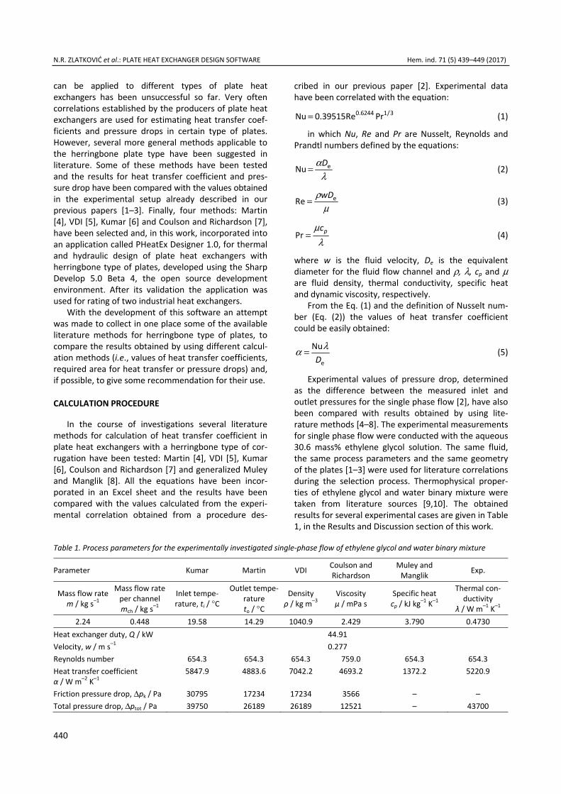
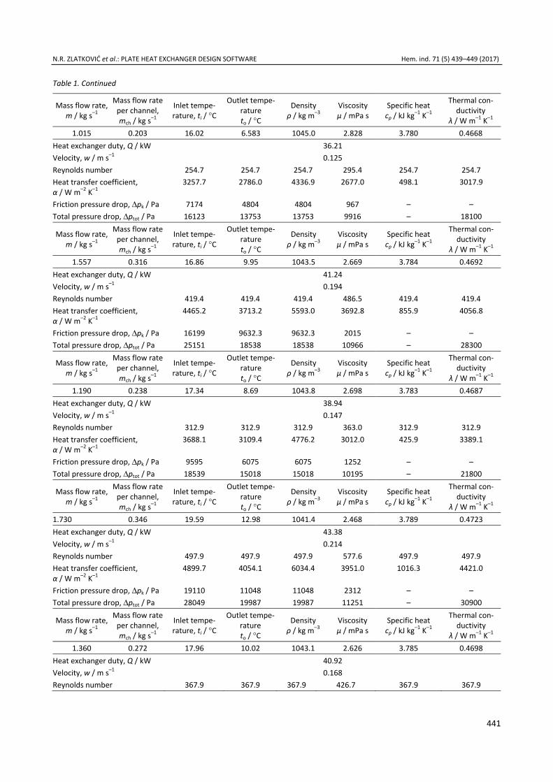
Experimental values of pressure drop, determined as the difference between the measured inlet and outlet pressures for the single phase flow [2], have also been compared with results obtained by using lite-rature methods [4–8]. The experimental measurements for single phase flow were conducted with the aqueous 30.6 mass% ethylene glycol solution. The same fluid, the same process parameters and the same geometry of the plates [1–3] were used for literature correlations during the selection process. Thermophysical proper-ties of ethylene glycol and water binary mixture were taken from literature sources [9,10]. The obtained results for several experimental cases are given in Table 1, in the Results and Discussion section of this work.
Table 1. Process parameters for the experimentally investigated single-phase flow of ethylene glycol and water binary mixture
Parameter Kumar Martin VDI Coulson and Richardson
Muley and Manglik Exp.
Mass flow rate m / kg s–1
Mass flow rate per channel mch / kg s–1
Inlet tempe-rature, ti / °C
Outlet tempe-rature to / °C
Densityρ / kg m–3
Viscosity µ / mPa s
Specific heat cp / kJ kg–1 K–1
Thermal con-ductivity
λ / W m–1 K–1 2.24 0.448 19.58 14.29 1040.9 2.429 3.790 0.4730
Heat exchanger duty, Q / kW 44.91 Velocity, w / m s–1 0.277 Reynolds number 654.3 654.3 654.3 759.0 654.3 654.3 Heat transfer coefficient α / W m–2 K–1
5847.9 4883.6 7042.2 4693.2 1372.2 5220.9
Friction pressure drop, Δpk / Pa 30795 17234 17234 3566 – – Total pressure drop, Δptot / Pa 39750 26189 26189 12521 – 43700
N.R. ZLATKOVIĆ et al.: PLATE HEAT EXCHANGER DESIGN SOFTWARE Hem. ind. 71 (5) 439–449 (2017)
441
Table 1. Continued
Mass flow rate, m / kg s–1
Mass flow rate per channel, mch / kg s–1
Inlet tempe-rature, ti / °C
Outlet tempe-rature to / °C
Density ρ / kg m–3
Viscosity µ / mPa s
Specific heat cp / kJ kg–1 K–1
Thermal con-ductivity
λ / W m–1 K–1 1.015 0.203 16.02 6.583 1045.0 2.828 3.780 0.4668
Heat exchanger duty, Q / kW 36.21 Velocity, w / m s–1 0.125 Reynolds number 254.7 254.7 254.7 295.4 254.7 254.7 Heat transfer coefficient, α / W m–2 K–1
3257.7 2786.0 4336.9 2677.0 498.1 3017.9
Friction pressure drop, Δpk / Pa 7174 4804 4804 967 – – Total pressure drop, Δptot / Pa 16123 13753 13753 9916 – 18100
Mass flow rate, m / kg s–1
Mass flow rate per channel, mch / kg s–1
Inlet tempe-rature, ti / °C
Outlet tempe-rature to / °C
Density ρ / kg m–3
Viscosity µ / mPa s
Specific heat cp / kJ kg–1 K–1
Thermal con-ductivity
λ / W m–1 K–1 1.557 0.316 16.86 9.95 1043.5 2.669 3.784 0.4692
Heat exchanger duty, Q / kW 41.24 Velocity, w / m s–1 0.194 Reynolds number 419.4 419.4 419.4 486.5 419.4 419.4 Heat transfer coefficient, α / W m–2 K–1
4465.2 3713.2 5593.0 3692.8 855.9 4056.8
Friction pressure drop, Δpk / Pa 16199 9632.3 9632.3 2015 – – Total pressure drop, Δptot / Pa 25151 18538 18538 10966 – 28300
Mass flow rate, m / kg s–1
Mass flow rate per channel, mch / kg s–1
Inlet tempe-rature, ti / °C
Outlet tempe-rature to / °C
Density ρ / kg m–3
Viscosity µ / mPa s
Specific heat cp / kJ kg–1 K–1
Thermal con-ductivity
λ / W m–1 K–1 1.190 0.238 17.34 8.69 1043.8 2.698 3.783 0.4687
Heat exchanger duty, Q / kW 38.94 Velocity, w / m s–1 0.147 Reynolds number 312.9 312.9 312.9 363.0 312.9 312.9 Heat transfer coefficient, α / W m–2 K–1
3688.1 3109.4 4776.2 3012.0 425.9 3389.1
Friction pressure drop, Δpk / Pa 9595 6075 6075 1252 – – Total pressure drop, Δptot / Pa 18539 15018 15018 10195 – 21800
Mass flow rate, m / kg s–1
Mass flow rate per channel, mch / kg s–1
Inlet tempe-rature, ti / °C
Outlet tempe-rature to / °C
Density ρ / kg m–3
Viscosity µ / mPa s
Specific heat cp / kJ kg–1 K–1
Thermal con-ductivity
λ / W m–1 K–1 1.730 0.346 19.59 12.98 1041.4 2.468 3.789 0.4723 Heat exchanger duty, Q / kW 43.38 Velocity, w / m s–1 0.214 Reynolds number 497.9 497.9 497.9 577.6 497.9 497.9 Heat transfer coefficient, α / W m–2 K–1
4899.7 4054.1 6034.4 3951.0 1016.3 4421.0
Friction pressure drop, Δpk / Pa 19110 11048 11048 2312 – – Total pressure drop, Δptot / Pa 28049 19987 19987 11251 – 30900
Mass flow rate, m / kg s–1
Mass flow rate per channel, mch / kg s–1
Inlet tempe-rature, ti / °C
Outlet tempe-rature to / °C
Density ρ / kg m–3
Viscosity µ / mPa s
Specific heat cp / kJ kg–1 K–1
Thermal con-ductivity
λ / W m–1 K–1 1.360 0.272 17.96 10.02 1043.1 2.626 3.785 0.4698
Heat exchanger duty, Q / kW 40.92 Velocity, w / m s–1 0.168 Reynolds number 367.9 367.9 367.9 426.7 367.9 367.9
N.R. ZLATKOVIĆ et al.: PLATE HEAT EXCHANGER DESIGN SOFTWARE Hem. ind. 71 (5) 439–449 (2017)
442
Table 1. Continued
Mass flow rate, m / kg s–1
Mass flow rateper channel, mch / kg s–1
Inlet tempe-rature, ti / °C
Outlet tempe-rature to / °C
Densityρ / kg m–3
Viscosity µ / mPa s
Specific heat cp / kJ kg–1 K–1
Thermal con-ductivity
λ / W m–1 K–1 1.360 0.272 17.96 10.02 1043.1 2.626 3.785 0.4698
Heat transfer coefficient, α / W m–2 K–1
4075.8 3407.0 5177.5 3314.0 736.7 3721.7
Friction pressure drop, Δpk / Pa 12292 7499 7499 1562 – – Total pressure drop, Δptot / Pa 21234 16441 16441 10504 – 22800
Mass flow rate, m / kg s–1
Mass flow rate per channel, mch / kg s–1
Inlet tempe-rature, ti / °C
Outlet tempe-rature to / °C
Densityρ / kg m–3
Viscosity µ / mPa s
Specific heat cp / kJ kg–1 K–1
Thermal con-ductivity
λ / W m–1 K–1 1.910 0.382 17.51 11.74 1042.5 2.576 3.786 0.4705
Heat exchanger duty, Q / kW 41.72 Velocity, w / m s–1 0.236 Reynolds number 526.1 526.1 526.1 610.3 526.1 526.1 Heat transfer coefficient, α / W m–2 K–1
5139.7 4244.7 6293.8 4151.2 1091.8 4628.4
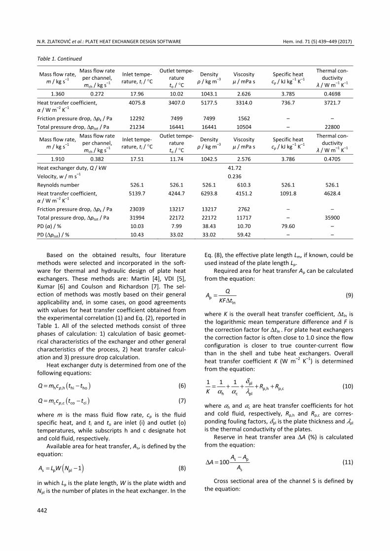
Friction pressure drop, Δpk / Pa 23039 13217 13217 2762 – – Total pressure drop, Δptot / Pa 31994 22172 22172 11717 – 35900 PD (α) / % 10.03 7.99 38.43 10.70 79.60 – PD (Δptot) / % 10.43 33.02 33.02 59.42 – –
Based on the obtained results, four literature
methods were selected and incorporated in the soft-ware for thermal and hydraulic design of plate heat exchangers. These methods are: Martin [4], VDI [5], Kumar [6] and Coulson and Richardson [7]. The sel-ection of methods was mostly based on their general applicability and, in some cases, on good agreements with values for heat transfer coefficient obtained from the experimental correlation (1) and Eq. (2), reported in Table 1. All of the selected methods consist of three phases of calculation: 1) calculation of basic geomet-rical characteristics of the exchanger and other general characteristics of the process, 2) heat transfer calcul-ation and 3) pressure drop calculation.
Heat exchanger duty is determined from one of the following equations:
( )= −h ,h hi hopQ m c t t (6)
( )= −c ,c co cipQ m c t t (7)
where m is the mass fluid flow rate, cp is the fluid specific heat, and ti and to are inlet (i) and outlet (o) temperatures, while subscripts h and c designate hot and cold fluid, respectively.
Available area for heat transfer, As, is defined by the equation:
( )= −s p pl 1A L W N (8)
in which Lp is the plate length, W is the plate width and Npl is the number of plates in the heat exchanger. In the
Eq. (8), the effective plate length Lm, if known, could be used instead of the plate length Lp.
Required area for heat transfer Ap can be calculated from the equation:
=Δp
ln
QAKF t
(9)
where K is the overall heat transfer coefficient, Δtln is the logarithmic mean temperature difference and F is the correction factor for Δtln . For plate heat exchangers the correction factor is often close to 1.0 since the flow configuration is closer to true counter-current flow than in the shell and tube heat exchangers. Overall heat transfer coefficient K (W m–2 K–1) is determined from the equation:
δα α λ
= + + + +plp,h p,c
h c pl
1 1 1 R RK
(10)
where h and c are heat transfer coefficients for hot and cold fluid, respectively, Rp,h and Rp,c are corres-ponding fouling factors, pl is the plate thickness and pl is the thermal conductivity of the plates.
Reserve in heat transfer area ΔA (%) is calculated from the equation:
−Δ = s p
s100
A AA
A (11)
Cross sectional area of the channel S is defined by the equation:
N.R. ZLATKOVIĆ et al.: PLATE HEAT EXCHANGER DESIGN SOFTWARE Hem. ind. 71 (5) 439–449 (2017)
443
=S BW (12)
where B is the average distance between adjacent plates determined as:
= 2B a (13)
in Martin [4] and VDI [5] correlations. In Kumar [6] and Coulson and Richardson [7] methods parameter B is calculated from the expression:
δ= −p plB p (14)
in which pp (m) is the plate profile pitch and δpl (m) is the plate thickness.
Equivalent diameter De for the fluid flow channel in Coulson and Richardson [7] method is determined as:
=e 2D B (15)
In Martin [4], VDI [5] and Kumar[6] methods the following equation for equivalent diameter is used:
μ=e
p
2BD (16)
where μp is the plate enhancement factor due to cor-rugation. If not given by the plate manufacturer, it could be calculated as a function of average distance between adjacent plates (B) and wave length of the plate (Λ) according to the described procedure [4,5]:
( )μ = + + + +2 2p
1 1 1 4 1 / 26
X X (17)
where X is calculated as:
πΛ
= BX (18)
Heat transfer coefficient in Martin [4] and VDI [5] methods is determined from the Eq. (5). The difference between these two methods is in the equations used for calculating the Nusselt number. In Martin [4] method, the following equation is used:
( )μ μ ζ α= 1/3 1/6 2 0.374w plNu 0.122Pr ( / ) sin(2 Re ) (19)
while in VDI correlation [5], the Nusselt number is cal-culated from the equation:
ξ= 1/3eNu 1.615[( Re/ 64)RePr / ]D L (20)
In both equations Re and Pr are Reynolds and Prandtl numbers of the fluid, μ (Pa s) and μw (Pa s) are viscosities of the fluid at the mean fluid temperature and wall temperature, respectively, while ξ represents the fluid friction coefficient. The friction coefficient ξ depends on three friction components (ξ0, ξ1,0, ξ1) and plate corrugation angle αpl. Friction components (ξ0, ξ1,0, ξ1) are functions of the Reynolds number and
operating conditions accounted for by empirical coef-ficients and constants. More details on calculation pro-cedures could be found elsewhere [4,5]. The charac-teristic length L (m) could be determined as a function of the corrugation angle (αpl) and wave length (Λ), from the equation:
Λα
=plsin(2 )
L (21)
The heat transfer coefficient in Kumar method [6] is calculated using the expression:
μλμ
α
=
0.170.33
hw
e
Prj
D (22)
Heat transfer factor (jh) is determined as a function of Reynolds number (Re) and plate profile angle ( β α= − pl90 ) according to the described procedure [6].
Coulson and Richardson [7] method uses the fol-lowing expression for calculation of the heat transfer coefficient:
( )α μ μλ
= 0.140.65 0.4e 0.26Re Pr / wD
(23)
The total fluid pressure drop Δptot is the sum of three values: a) pressure drop in exchanger channels (friction pressure drop), b) pressure drop in nozzles, and c) pressure drop due to elevation. The pressure drop in exchanger channels according to Martin [4] and VDI [5] methods is calculated:
ξρΔ =
2p
ke2
w Lp N
D (24)
in which N represents the number of fluid passes through the exchanger while ξ is the fluid friction coefficient, already mentioned in the Eqs. (19) and (20). In the Kumar method [6], friction coefficient ξ is rep-laced by the Fanning – type friction factor f, and a cor-rection factor due to the wall temperature influence is taken into account:
ρ
μμ
Δ =
2p
k 0.17
ee
4
2
f w Lp N
D
(25)
The friction factor, similar to the heat transfer factor (jh), is determined as a function of the Reynolds number (Re) and plate profile angle ( β α= − pl90 ) according to the procedure described in [6].
According to Coulson and Richardson [7], pressure drop in exchanger channels is calculated:
N.R. ZLATKOVIĆ et al.: PLATE HEAT EXCHANGER DESIGN SOFTWARE Hem. ind. 71 (5) 439–449 (2017)
444
ρΔ =
2f p
ke
82
j w Lp N
D (26)
while the friction factor jf can be determined from the expression:
−= 0.3f 0.6Rej (27)
Pressure drop in nozzles, in all four selected methods, is calculated from the equation:
ρΔ =
2p
p1.3
2w
p N (28)
where wp represents the fluid velocity in nozzles. Pressure drop due to elevation has to be taken into
account in the case of uneven number of fluid passes, and can be determined from the equation:
ρΔ =el pp gL (29)
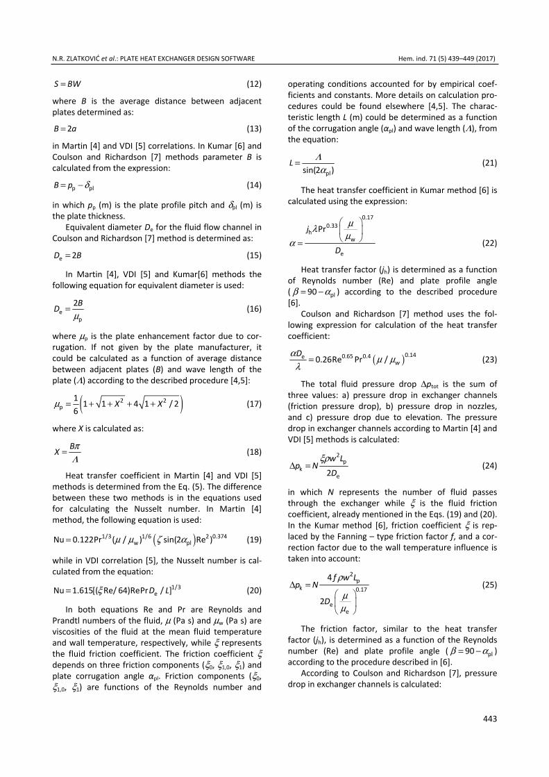
Software description The software PHeatEx Designer 1.0 for thermal and
hydraulic calculation of plate heat exchangers has been developed in Sharp Develop 5.0 Beta 4, the open source development environment. The software is acti-vated by clicking the shortcut shown in Figure 1a. After running the application, the Login Form window, shown in Figure 1b, will appear.
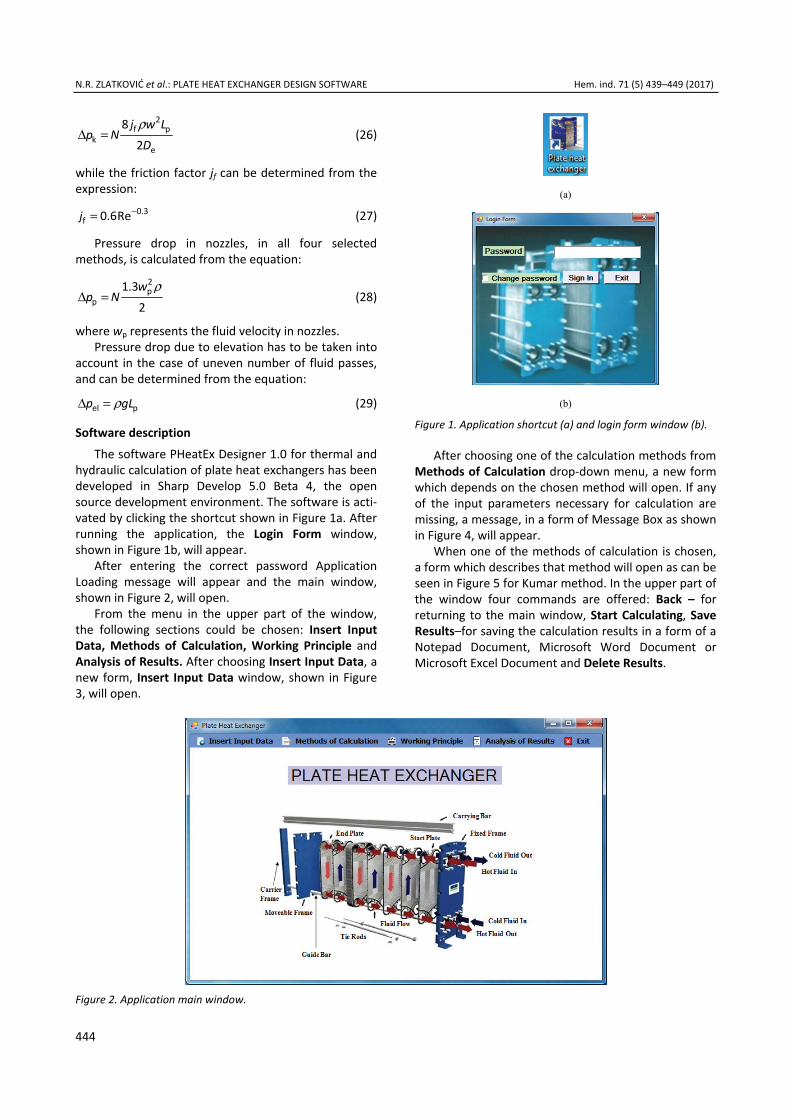
After entering the correct password Application Loading message will appear and the main window, shown in Figure 2, will open.
From the menu in the upper part of the window, the following sections could be chosen: Insert Input Data, Methods of Calculation, Working Principle and Analysis of Results. After choosing Insert Input Data, a new form, Insert Input Data window, shown in Figure 3, will open.
(a)
(b) Figure 1. Application shortcut (a) and login form window (b).
After choosing one of the calculation methods from Methods of Calculation drop-down menu, a new form which depends on the chosen method will open. If any of the input parameters necessary for calculation are missing, a message, in a form of Message Box as shown in Figure 4, will appear.
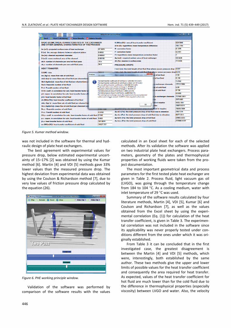
When one of the methods of calculation is chosen, a form which describes that method will open as can be seen in Figure 5 for Kumar method. In the upper part of the window four commands are offered: Back – for returning to the main window, Start Calculating, Save Results–for saving the calculation results in a form of a Notepad Document, Microsoft Word Document or Microsoft Excel Document and Delete Results.
Figure 2. Application main window.

N.R. ZLATKOVIĆ et al.: PLATE HEAT EXCHANGER DESIGN SOFTWARE Hem. ind. 71 (5) 439–449 (2017)
445
Figure 4. Missing parameter warning window.
After running the calculation, all output parameters will be shown in a separate window and the most important results (heat transfer coefficients of both fluids, overall heat transfer coefficient, available sur-face area, required surface area, total pressure drops of both fluids, etc.) will be also shown in a Message Box.
The Working Principle window, shown in Figure 6, contains two video clips which show working principle and components of a plate exchanger.
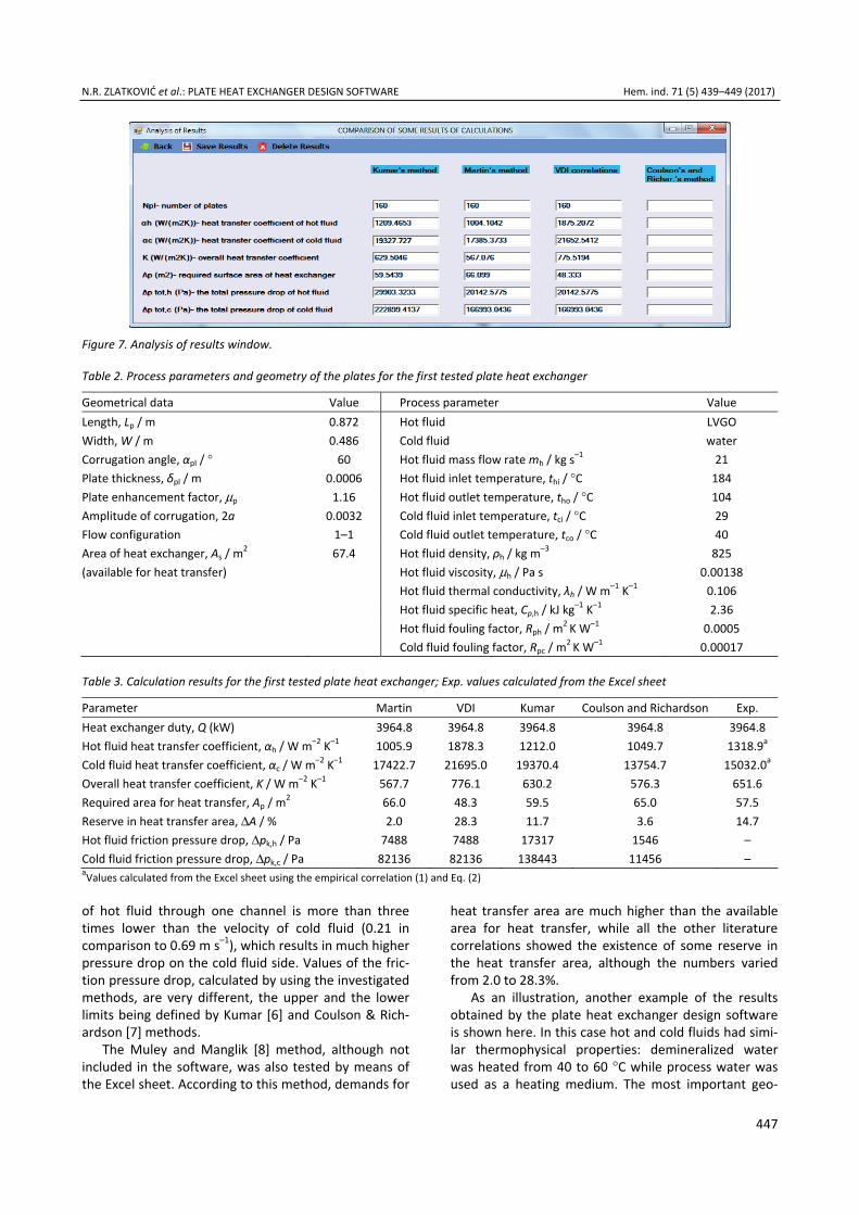
The Analysis of Results window is a part of the software, which allows comparison of the results obtained by different methods. If so desired, some of the methods could be excluded from the comparative analysis, as shown in Figure 7.
RESULTS AND DISCUSSION
The process of selection of literature methods to be used for the development of the application PHeatEx Designer 1.0 for thermal and hydraulic calculations of plate heat exchangers, was based on comparison of the values determined using literature methods [4–9] with experimental data measured on the setup described in
our previous work [2]. A survey of the obtained results for seven experimental cases is given in Table 1. Lite-rature methods were assessed by calculating percent-age deviation for heat transfer coefficient and pressure drop from the equation:
=
−= exp cal
exp1
100( )m
i i
Y YPD Y
m Y (30)
where Yexp and Ycal denote experimental and calculated values of the heat transfer coefficient and pressure drop, while m is the number of experimental data points.
From the Table 1 it can be concluded that the best agreement with experimental values for heat transfer coefficient, with around 8% deviation, was obtained by using the Martin method [4]. This result is considered as very good since the experimental uncertainty in determination of heat transfer coefficient is estimated between 10% and 15% [2]. Satisfactory results, below the value of experimental uncertainty, were also obtained with Kumar [6] and Coulson and Richardson [7] methods, with the difference that the Kumar method [6] gave higher and Coulson and Richardson method [7] lower values of the heat transfer coefficient than the experimental ones. VDI method [5], which is based on similar calculation procedure as the Martin method [4], unexpectedly gave much higher deviation, around 38%. The Muley and Manglik method [8] has been known for giving considerably lower values for Nusselt number and heat transfer coefficient than the other literature methods, and this was confirmed by our results, given in Table 1. Consequently, this method
Figure 3. Insert input data window.
N.R. ZLATKOVIĆ et al.: PLATE HEAT EXCHANGER DESIGN SOFTWARE Hem. ind. 71 (5) 439–449 (2017)
446
was not included in the software for thermal and hyd-raulic design of plate heat exchangers.
The best agreement with experimental values for pressure drop, below estimated experimental uncert-ainty of 15–17% [2] was obtained by using the Kumar method [6]. Martin [4] and VDI [5] methods gave 33% lower values than the measured pressure drop. The highest deviation from experimental data was obtained by using the Coulson & Richardson method [7], due to very low values of friction pressure drop calculated by the equation (26).
Figure 6. PHE working principle window.
Validation of the software was performed by comparison of the software results with the values
calculated in an Excel sheet for each of the selected methods. After its validation the software was applied on two industrial plate heat exchangers. Process para-meters, geometry of the plates and thermophysical properties of working fluids were taken from the pro-ject documentation.
The most important geometrical data and process parameters for the first tested plate heat exchanger are given in Table 2. Process fluid, light vacuum gas oil (LVGO), was going through the temperature change from 184 to 104 °C. As a cooling medium, water with inlet temperature of 29 °C was used.
Summary of the software results calculated by four literature methods, Martin [4], VDI [5], Kumar [6] and Coulson and Richardson [7], as well as the values obtained from the Excel sheet by using the experi-mental correlation (Eq. (1)) for calculation of the heat transfer coefficient, is given in Table 3. The experimen-tal correlation was not included in the software since its applicability was never properly tested under con-ditions different from the ones under which it was ori-ginally established.
From Table 3 it can be concluded that in the first investigated case, the greatest disagreement is between the Martin [4] and VDI [5] methods, which were, interestingly, both established by the same author. These two methods give the upper and lower limits of possible values for the heat transfer coefficient and consequently the area required for heat transfer. As expected, values of the heat transfer coefficient for hot fluid are much lower than for the cold fluid due to the difference in thermophysical properties (especially viscosity) between LVGO and water. Also, the velocity
Figure 5. Kumar method window.
N.R. ZLATKOVIĆ et al.: PLATE HEAT EXCHANGER DESIGN SOFTWARE Hem. ind. 71 (5) 439–449 (2017)
447
Figure 7. Analysis of results window.
Table 2. Process parameters and geometry of the plates for the first tested plate heat exchanger
Geometrical data Value Process parameter Value Length, Lp / m 0.872 Hot fluid LVGO Width, W / m 0.486 Cold fluid water Corrugation angle, αpl / ° 60 Hot fluid mass flow rate mh / kg s–1 21 Plate thickness, δpl / m 0.0006 Hot fluid inlet temperature, thi / °C 184 Plate enhancement factor, μp 1.16 Hot fluid outlet temperature, tho / °C 104 Amplitude of corrugation, 2a 0.0032 Cold fluid inlet temperature, tci / °C 29 Flow configuration 1–1 Cold fluid outlet temperature, tco / °C 40 Area of heat exchanger, As / m2 67.4 Hot fluid density, ρh / kg m–3 825 (available for heat transfer) Hot fluid viscosity, μh / Pa s 0.00138 Hot fluid thermal conductivity, λh / W m–1 K–1 0.106 Hot fluid specific heat, Cp,h / kJ kg–1 K–1 2.36 Hot fluid fouling factor, Rph / m2 K W–1 0.0005 Cold fluid fouling factor, Rpc / m2 K W–1 0.00017
Table 3. Calculation results for the first tested plate heat exchanger; Exp. values calculated from the Excel sheet
Parameter Martin VDI Kumar Coulson and Richardson Exp.Heat exchanger duty, Q (kW) 3964.8 3964.8 3964.8 3964.8 3964.8 Hot fluid heat transfer coefficient, αh / W m–2 K–1 1005.9 1878.3 1212.0 1049.7 1318.9a
Cold fluid heat transfer coefficient, αc / W m–2 K–1 17422.7 21695.0 19370.4 13754.7 15032.0a
Overall heat transfer coefficient, K / W m–2 K–1 567.7 776.1 630.2 576.3 651.6 Required area for heat transfer, Ap / m2 66.0 48.3 59.5 65.0 57.5 Reserve in heat transfer area, ΔA / % 2.0 28.3 11.7 3.6 14.7 Hot fluid friction pressure drop, Δpk,h / Pa 7488 7488 17317 1546 – Cold fluid friction pressure drop, Δpk,c / Pa 82136 82136 138443 11456 – aValues calculated from the Excel sheet using the empirical correlation (1) and Eq. (2)
of hot fluid through one channel is more than three times lower than the velocity of cold fluid (0.21 in comparison to 0.69 m s–1), which results in much higher pressure drop on the cold fluid side. Values of the fric-tion pressure drop, calculated by using the investigated methods, are very different, the upper and the lower limits being defined by Kumar [6] and Coulson & Rich-ardson [7] methods.
The Muley and Manglik [8] method, although not included in the software, was also tested by means of the Excel sheet. According to this method, demands for
heat transfer area are much higher than the available area for heat transfer, while all the other literature correlations showed the existence of some reserve in the heat transfer area, although the numbers varied from 2.0 to 28.3%.
As an illustration, another example of the results obtained by the plate heat exchanger design software is shown here. In this case hot and cold fluids had simi-lar thermophysical properties: demineralized water was heated from 40 to 60 °C while process water was used as a heating medium. The most important geo-
N.R. ZLATKOVIĆ et al.: PLATE HEAT EXCHANGER DESIGN SOFTWARE Hem. ind. 71 (5) 439–449 (2017)
448
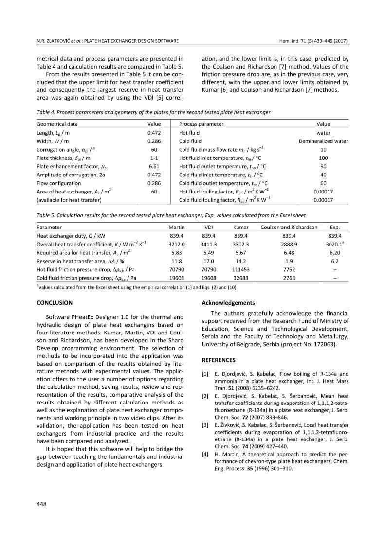
metrical data and process parameters are presented in Table 4 and calculation results are compared in Table 5.
From the results presented in Table 5 it can be con-cluded that the upper limit for heat transfer coefficient and consequently the largest reserve in heat transfer area was again obtained by using the VDI [5] correl-
ation, and the lower limit is, in this case, predicted by the Coulson and Richardson [7] method. Values of the friction pressure drop are, as in the previous case, very different, with the upper and lower limits obtained by Kumar [6] and Coulson and Richardson [7] methods.
Table 4. Process parameters and geometry of the plates for the second tested plate heat exchanger
Geometrical data Value Process parameter Value Length, Lp / m 0.472 Hot fluid water Width, W / m 0.286 Cold fluid Demineralized waterCorrugation angle, αpl / ° 60 Cold fluid mass flow rate mh / kg s–1 10 Plate thickness, δpl / m 1-1 Hot fluid inlet temperature, thi / °C 100 Plate enhancement factor, μp 6.61 Hot fluid outlet temperature, tho / °C 90 Amplitude of corrugation, 2a 0.472 Cold fluid inlet temperature, tci / °C 40 Flow configuration 0.286 Cold fluid outlet temperature, tco / °C 60 Area of heat exchanger, As / m2 60 Hot fluid fouling factor, Rph / m2 K W–1 0.00017 (available for heat transfer) Cold fluid fouling factor, Rpc / m2 K W–1 0.00017
Table 5. Calculation results for the second tested plate heat exchanger; Exp. values calculated from the Excel sheet
Parameter Martin VDI Kumar Coulson and Richardson Exp.Heat exchanger duty, Q / kW 839.4 839.4 839.4 839.4 839.4 Overall heat transfer coefficient, K / W m–2 K–1 3212.0 3411.3 3302.3 2888.9 3020.1a
Required area for heat transfer, Ap / m2 5.83 5.49 5.67 6.48 6.20 Reserve in heat transfer area, ΔA / % 11.8 17.0 14.2 1.9 6.2 Hot fluid friction pressure drop, Δpk,h / Pa 70790 70790 111453 7752 – Cold fluid friction pressure drop, Δpk,c / Pa 19608 19608 32688 2768 – aValues calculated from the Excel sheet using the empirical correlation (1) and Eqs. (2) and (10)
CONCLUSION
Software PHeatEx Designer 1.0 for the thermal and hydraulic design of plate heat exchangers based on four literature methods: Kumar, Martin, VDI and Coul-son and Richardson, has been developed in the Sharp Develop programming environment. The selection of methods to be incorporated into the application was based on comparison of the results obtained by lite-rature methods with experimental values. The applic-ation offers to the user a number of options regarding the calculation method, saving results, review and rep-resentation of the results, comparative analysis of the results obtained by different calculation methods as well as the explanation of plate heat exchanger compo-nents and working principle in two video clips. After its validation, the application has been tested on heat exchangers from industrial practice and the results have been compared and analyzed.
It is hoped that this software will help to bridge the gap between teaching the fundamentals and industrial design and application of plate heat exchangers.
Acknowledgements The authors gratefully acknowledge the financial
support received from the Research Fund of Ministry of Education, Science and Technological Development, Serbia and the Faculty of Technology and Metallurgy, University of Belgrade, Serbia (project No. 172063).
REFERENCES
[1] E. Djordjević, S. Kabelac, Flow boiling of R-134a and ammonia in a plate heat exchanger, Int. J. Heat Mass Tran. 51 (2008) 6235–6242.
[2] E. Djordjević, S. Kabelac, S. Šerbanović, Mean heat transfer coefficients during evaporation of 1,1,1,2-tetra-fluoroethane (R-134a) in a plate heat exchanger, J. Serb. Chem. Soc. 72 (2007) 833–846.
[3] E. Živković, S. Kabelac, S. Šerbanović, Local heat transfer coefficients during evaporation of 1,1,1,2-tetrafluoro-ethane (R-134a) in a plate heat exchanger, J. Serb. Chem. Soc. 74 (2009) 427–440.
[4] H. Martin, A theoretical approach to predict the per-formance of chevron-type plate heat exchangers, Chem. Eng. Process. 35 (1996) 301–310.
N.R. ZLATKOVIĆ et al.: PLATE HEAT EXCHANGER DESIGN SOFTWARE Hem. ind. 71 (5) 439–449 (2017)
449
[5] H. Martin, Druckverlust und Wärmeübergang in Platten-wärmeübertragern, in: VDI – Wärmeatlas, Springer Verlag, Heidelberg, 2002, pp. Mm1–Mm7.
[6] H. Kumar, The plate heat exchanger: construction and design, in Proceedings of First UK National Conference on Heat Transfer, University of Leeds, Inst. Chem. Eng. Symp. Series No. 86, Leeds, UK, 1984, pp. 1275–1288.
[7] R.K. Sinnott, Chemical Engineering Design, Coulson & Richardson’s Chemical Engineering, Vol. 6, 4th ed., Else-vier Butterworth-Heinemann, Oxford, 2005.
[8] S. Kakaç, H. Liu, Heat Exchangers: selection, rating and thermal design, 2nd ed., CRC Press, Boca Raton, FL, 2002.
[9] T. Sun, A.S. Teja, Density, Viscosity, and Thermal Con-ductivity of Aqueous Ethylene, Diethylene, and Triethyl-ene Glycol Mixtures between 290 K and 450 K, J. Chem. Eng. Data 48 (2003) 198–202.
[10] C. Yang, P. Ma, F. Jing, D. Tang, Excess Molar Volumes, Viscosities, and Heat Capacities for the Mixtures of Ethylene Glycol + Water from 273.15 K to 353.15 K, J. Chem. Eng. Data 48 (2003) 836–840.
IZVOD
PROGRAMSKI PAKET ZA PROJEKTOVANJE PLOČASTOG RAZMENJIVAČA TOPLOTE ZA INDUSTRIJSKU I EDUKATIVNU PRIMENU Nikola R. Zlatković, Divna M. Majstorović, Mirjana Lj. Kijevčanin, Emila M. Živković
Tehnološko-metalurški fakultet, Univerzitet u Beogradu, Karnegijeva 4, 11120 Beograd, Srbija
(Stručni rad)
Pločasti razmenjivači toplote su tip aparata koji danas nalazi veoma široku oblast primene, od prehrambene i hemijske industriji do elektroenergetskih pos-trojenja. Osnovni konstruktivni element ovih aparata je slog orebrenih metalnihploča. Orebrenja na pločama su tako dizajnirana da omogućavaju postizanje tur-bulentnog strujanja duž cele površine za toplotnu razmenu, čime se postižu najvišimogući koeficijenti prenosa toplote pri relativno maloj razlici temperatura fluida.Ovo dovodi do manje potrebne površine za toplotnu razmenu, manjih dimenzijaaparata i, u nekim slučajevima, manjeg broja razmenjivača toplote. Pored odličnihkarakteristika u pogledu prenosa toplote, imaju i brojne druge prednosti u odnosuna najčešće korišćene razmenjivače toplote sa cevnim snopom i omotačem: lakose sastavljaju i rastavljaju radi čišćenja i popravki, površina za toplotnu razmenu selako može menjati promenom broja ploča u slogu, mogu raditi pri vrlo malimrazlikama temperature fluida koji učestvuju u toplotnoj razmeni, a stvaranje one-čišćenja je manje izraženo zbog većih brzina strujanja i bolje distribucije tokafluida. Osnovni problem pri termohidrauličkom proračunu pločastih razmenjivačatoplote je ograničen broj literaturnih korelacija, posebno onih koje bi imale širiopseg primenljivosti, što je i razumljivo obzirom na različite geometrije i tipoveprofila ploča koji se javljaju kod ovih aparata. U ovom radu je testirano nekolikoliteraturnih metoda za proračun koeficijenta prelaza toplote i pada pritiska u plo-častom razmenjivaču toplote sa orebrenjem tipa “riblja kost” i dobijeni rezultatisu upoređeni sa eksperimentalno određenim vrednostima za koeficijent prelazatoplote i pad pritiska. Izabrane su četiri metode koje su ugrađene u programskipaket za termički i hidraulički proračun pločastog razmenjivača toplote razvijenogu okruženju Sharp Develop. Ovaj programski paket za termički i hidraulički pro-račun pločastog razmenjivača toplote koristi sledeće četiri metode proračuna:Martinov metod, VDI metod, Kumarov metod i metod Kulsona i Ričardsona (Coulson–Richardson). Razvijeni softver je vizuelno prikazan preko prozora zaunos ulaznih podataka, prozora za prikaz rezultata proračuna dobijenih svakom odmetoda, prozora na kome je prikazano poređenje najbitnijih rezultata proračunaza sve korišćene metode i pomoćnog prozora za prikaz principa rada pločastograzmenjivača toplote. Nakon izbora metoda, razvoja i verifikacije softvera pristu-pilo se njegovoj primeni na dva industrijska razmenjivača toplote.
Ključne reči: Pločasti razmenjivač toplote• Prenos toplote • Pad pritiska • Pro-gramski paket