plastic analysis 3rd year structural engineering 2010/11 · 2015-04-25 · stage 3 –...
TRANSCRIPT

Structural Analysis III
Dr. C. Caprani 1
Plastic Analysis
3rd Year
Structural Engineering
2010/11
Dr. Colin Caprani
Structural Analysis III
Dr. C. Caprani 2
Contents
1. Introduction ......................................................................................................... 4
1.1 Background ....................................................................................................... 4
2. Basis of Plastic Design ......................................................................................... 5
2.1 Material Behaviour ........................................................................................... 5
2.2 Cross Section Behaviour ................................................................................... 7
2.3 Plastic Hinge Formation ................................................................................. 24
3. Methods of Plastic Analysis .............................................................................. 28
3.1 Introduction ..................................................................................................... 28
3.2 Incremental Analysis ...................................................................................... 29
3.3 Important Definitions ...................................................................................... 36
3.4 Equilibrium Method ........................................................................................ 38
3.5 Kinematic Method Using Virtual Work ......................................................... 42
3.6 Types of Plastic Collapse ................................................................................ 47
4. Theorems of Plastic Analysis ............................................................................ 48
4.1 Criteria ............................................................................................................ 48
4.2 The Upperbound (Unsafe) Theorem ............................................................... 49
4.3 The Lowerbound (Safe) Theorem .................................................................. 50
4.4 The Uniqueness Theorem ............................................................................... 51
4.5 Corollaries of the Theorems ........................................................................... 52
4.6 Application of the Theorems .......................................................................... 53
4.7 Plastic Design ................................................................................................. 58
4.8 Summary of Important Points ......................................................................... 61
5. Plastic Analysis of Beams.................................................................................. 62
5.1 Example 1 – Fixed-Fixed Beam with Point Load .......................................... 62
5.2 Example 2 – Propped Cantilever with Two Point Loads ............................... 65
5.3 Example 3 – Propped Cantilever under UDL ................................................. 71
5.4 Continuous Beams .......................................................................................... 76

Structural Analysis III
Dr. C. Caprani 3
5.5 Example 4 – Continuous Beam ...................................................................... 80
5.6 Problems ......................................................................................................... 85
6. Plastic Analysis of Frames ................................................................................ 87
6.1 Additional Aspects for Frames ....................................................................... 87
6.2 Example 5 –Simple Portal Frame ................................................................... 90
6.3 Example 6 –Portal Frame with Multiple Loads ............................................. 96
6.4 Example 7 – Portal Frame with Crane Loads, Summer 1997 ...................... 104
6.5 Example 8 – Oblique Frame, Sumer 1999 ................................................... 108
6.6 Problems ....................................................................................................... 120
7. Past Exam Questions ....................................................................................... 121
7.1 Sumer 2000 ................................................................................................... 121
7.2 Summer 2001 ................................................................................................ 122
7.3 Summer 2004 ................................................................................................ 123
7.4 Summer 2005 ................................................................................................ 124
7.5 Summer 2007 ................................................................................................ 125
7.6 Semester 2 2008 ............................................................................................ 126
7.7 Semester 2 2009 ............................................................................................ 127
7.8 Semester 2 2010 ............................................................................................ 128
8. References ........................................................................................................ 129
Structural Analysis III
Dr. C. Caprani 4
1. Introduction
1.1 Background
Up to now we have concentrated on the elastic analysis of structures. In these
analyses we used superposition often, knowing that for a linearly elastic structure it
was valid. However, an elastic analysis does not give information about the loads that
will actually collapse a structure. An indeterminate structure may sustain loads
greater than the load that first causes a yield to occur at any point in the structure. In
fact, a structure will stand as long as it is able to find redundancies to yield. It is only
when a structure has exhausted all of its redundancies will extra load causes it to fail.
Plastic analysis is the method through which the actual failure load of a structure is
calculated, and as will be seen, this failure load can be significantly greater than the
elastic load capacity.
To summarize this, Prof. Sean de Courcy (UCD) used to say:
“a structure only collapses when it has exhausted all means of standing”.
Before analysing complete structures, we review material and cross section behaviour
beyond the elastic limit.
Structural Analysis III
Dr. C. Caprani 5
2. Basis of Plastic Design
2.1 Material Behaviour
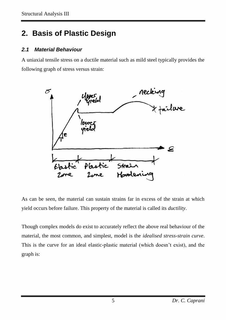
A uniaxial tensile stress on a ductile material such as mild steel typically provides the
following graph of stress versus strain:
As can be seen, the material can sustain strains far in excess of the strain at which
yield occurs before failure. This property of the material is called its ductility.
Though complex models do exist to accurately reflect the above real behaviour of the
material, the most common, and simplest, model is the idealised stress-strain curve.
This is the curve for an ideal elastic-plastic material (which doesn’t exist), and the
graph is:
Structural Analysis III
Dr. C. Caprani 6
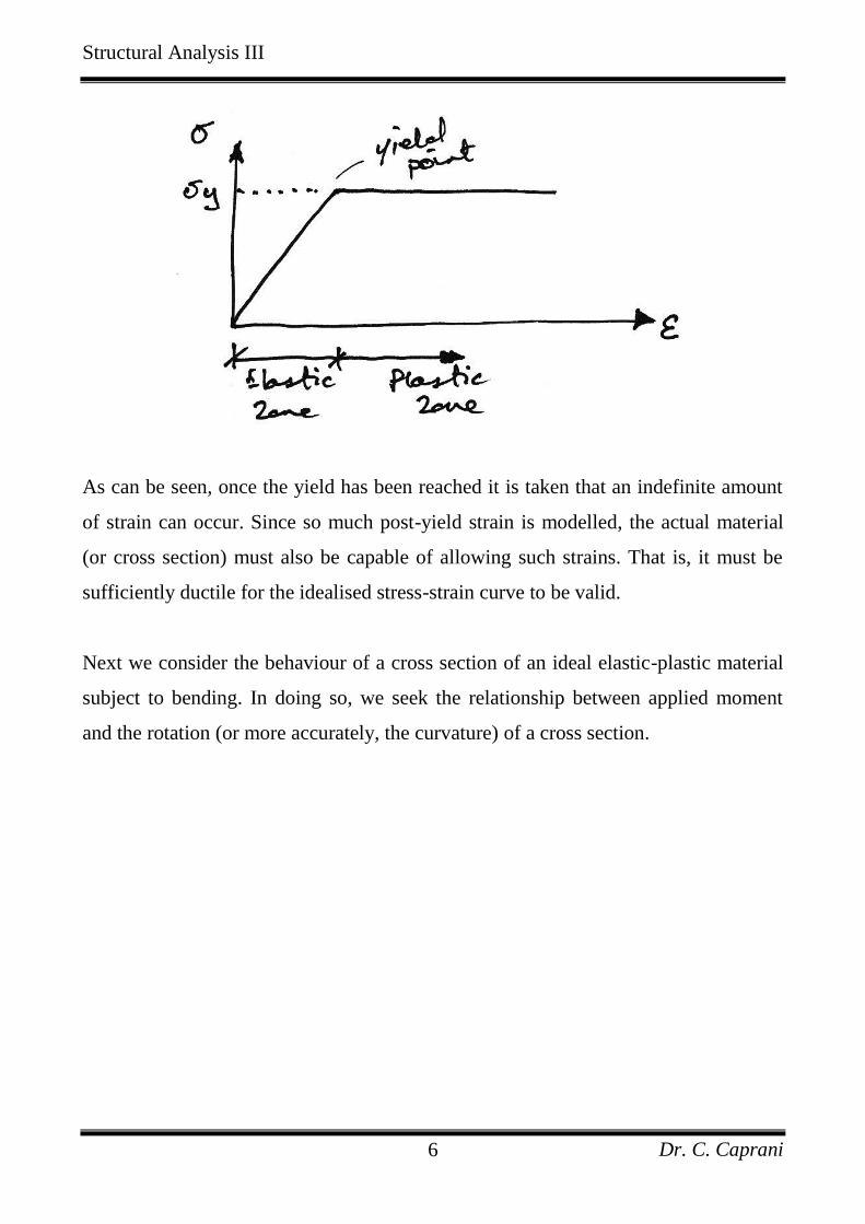
As can be seen, once the yield has been reached it is taken that an indefinite amount
of strain can occur. Since so much post-yield strain is modelled, the actual material
(or cross section) must also be capable of allowing such strains. That is, it must be
sufficiently ductile for the idealised stress-strain curve to be valid.
Next we consider the behaviour of a cross section of an ideal elastic-plastic material
subject to bending. In doing so, we seek the relationship between applied moment
and the rotation (or more accurately, the curvature) of a cross section.
Structural Analysis III
Dr. C. Caprani 7
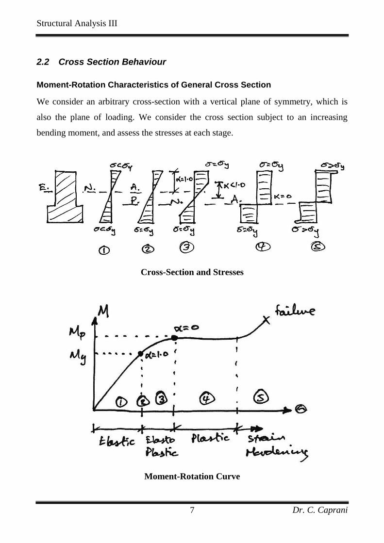
2.2 Cross Section Behaviour
Moment-Rotation Characteristics of General Cross Section
We consider an arbitrary cross-section with a vertical plane of symmetry, which is
also the plane of loading. We consider the cross section subject to an increasing
bending moment, and assess the stresses at each stage.
Cross-Section and Stresses
Moment-Rotation Curve
Structural Analysis III
Dr. C. Caprani 8
Stage 1 – Elastic Behaviour
The applied moment causes stresses over the cross-section that are all less than the
yield stress of the material.
Stage 2 – Yield Moment
The applied moment is just sufficient that the yield stress of the material is reached at
the outermost fibre(s) of the cross-section. All other stresses in the cross section are
less than the yield stress. This is limit of applicability of an elastic analysis and of
elastic design. Since all fibres are elastic, the ratio of the depth of the elastic to plastic
regions, 1.0 .
Stage 3 – Elasto-Plastic Bending
The moment applied to the cross section has been increased beyond the yield
moment. Since by the idealised stress-strain curve the material cannot sustain a stress
greater than yield stress, the fibres at the yield stress have progressed inwards
towards the centre of the beam. Thus over the cross section there is an elastic core
and a plastic region. The ratio of the depth of the elastic core to the plastic region is
1.0 0 . Since extra moment is being applied and no stress is bigger than the yield
stress, extra rotation of the section occurs: the moment-rotation curve losses its
linearity and curves, giving more rotation per unit moment (i.e. looses stiffness).
Stage 4 – Plastic Bending
The applied moment to the cross section is such that all fibres in the cross section are
at yield stress. This is termed the Plastic Moment Capacity of the section since there
are no fibres at an elastic stress, 0 . Also note that the full plastic moment requires
an infinite strain at the neutral axis and so is physically impossible to achieve.
However, it is closely approximated in practice. Any attempt at increasing the
moment at this point simply results in more rotation, once the cross-section has
Structural Analysis III
Dr. C. Caprani 9
sufficient ductility. Therefore in steel members the cross section classification must
be plastic and in concrete members the section must be under-reinforced.
Stage 5 – Strain Hardening
Due to strain hardening of the material, a small amount of extra moment can be
sustained.
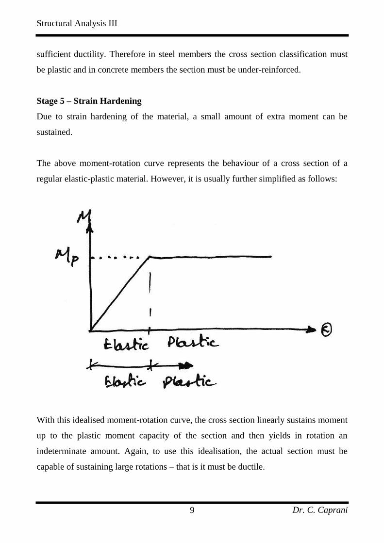
The above moment-rotation curve represents the behaviour of a cross section of a
regular elastic-plastic material. However, it is usually further simplified as follows:
With this idealised moment-rotation curve, the cross section linearly sustains moment
up to the plastic moment capacity of the section and then yields in rotation an
indeterminate amount. Again, to use this idealisation, the actual section must be
capable of sustaining large rotations – that is it must be ductile.
Structural Analysis III
Dr. C. Caprani 10
Plastic Hinge
Note that once the plastic moment capacity is reached, the section can rotate freely –
that is, it behaves like a hinge, except with moment of P
M at the hinge. This is
termed a plastic hinge, and is the basis for plastic analysis. At the plastic hinge
stresses remain constant, but strains and hence rotations can increase.
Structural Analysis III
Dr. C. Caprani 11
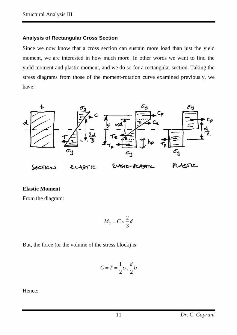
Analysis of Rectangular Cross Section
Since we now know that a cross section can sustain more load than just the yield
moment, we are interested in how much more. In other words we want to find the
yield moment and plastic moment, and we do so for a rectangular section. Taking the
stress diagrams from those of the moment-rotation curve examined previously, we
have:
Elastic Moment
From the diagram:
2
3Y
M C d
But, the force (or the volume of the stress block) is:
1
2 2Y
dC T b
Hence:
Structural Analysis III
Dr. C. Caprani 12
2
1 2
2 2 3
6
Y Y
Y
Y
dM b d
bd
Z
The term 2 6bd is thus a property of the cross section called the elastic section
modulus and it is termed Z.
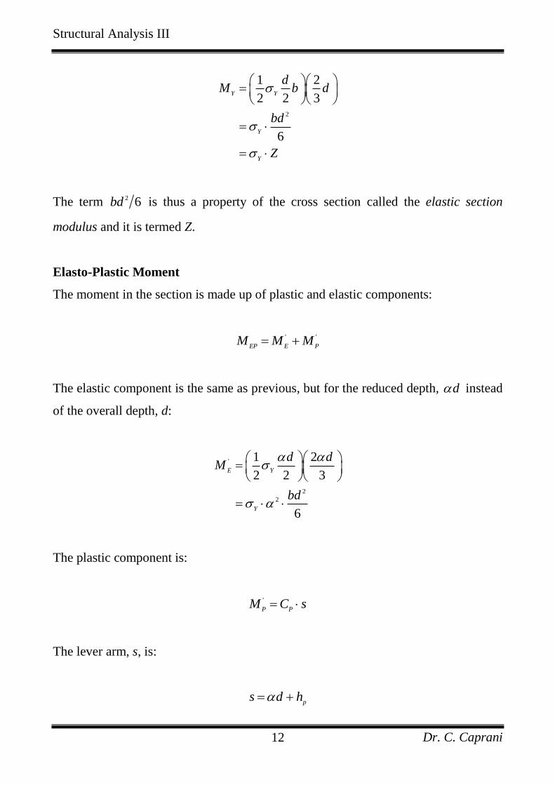
Elasto-Plastic Moment
The moment in the section is made up of plastic and elastic components:
' '
EP E PM M M
The elastic component is the same as previous, but for the reduced depth, d instead
of the overall depth, d:
'
2
2
1 2
2 2 3
6
E Y
Y
d dM
bd
The plastic component is:
'
P PM C s
The lever arm, s, is:
p
s d h
Structural Analysis III
Dr. C. Caprani 13
But
12 2
p
d d dh
Thus,
2 2
12
d ds d
d
The force is:
1
2
P Y p
Y
C h b
db
Hence,
'
2
2
1 12 2
14
P Y
Y
d dM b
bd
And so the total elasto-plastic moment is:
2 2
2 2
22
16 4
3
6 2
EP Y Y
Y
bd bdM
bd
Structural Analysis III
Dr. C. Caprani 14
Plastic Moment
From the stress diagram:
2
P
dM C
And the force is:
2
Y
dC T b
Hence:
2
2 2
4
P Y
Y
Y
bd dM
bd
S
The term 2 4bd is a property of the cross section called the plastic section modulus,
termed S.
Structural Analysis III
Dr. C. Caprani 15
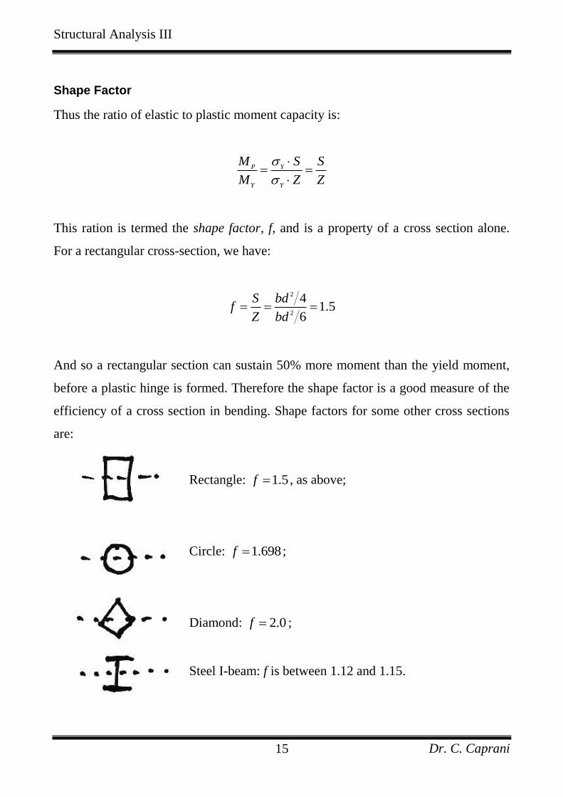
Shape Factor
Thus the ratio of elastic to plastic moment capacity is:
P Y
Y Y
M S S
M Z Z
This ration is termed the shape factor, f, and is a property of a cross section alone.
For a rectangular cross-section, we have:
2
2
41.5
6
S bdf
Z bd
And so a rectangular section can sustain 50% more moment than the yield moment,
before a plastic hinge is formed. Therefore the shape factor is a good measure of the
efficiency of a cross section in bending. Shape factors for some other cross sections
are:
Rectangle: 1.5f , as above;
Circle: 1.698f ;
Diamond: 2.0f ;
Steel I-beam: f is between 1.12 and 1.15.
Structural Analysis III
Dr. C. Caprani 16
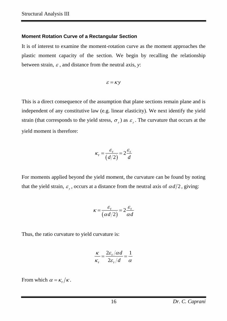
Moment Rotation Curve of a Rectangular Section
It is of interest to examine the moment-rotation curve as the moment approaches the
plastic moment capacity of the section. We begin by recalling the relationship
between strain, , and distance from the neutral axis, y:
y
This is a direct consequence of the assumption that plane sections remain plane and is
independent of any constitutive law (e.g. linear elasticity). We next identify the yield
strain (that corresponds to the yield stress, y
) as y
. The curvature that occurs at the
yield moment is therefore:
22
Y Y
Yd d
For moments applied beyond the yield moment, the curvature can be found by noting
that the yield strain, y
, occurs at a distance from the neutral axis of 2d , giving:
22
Y Y
d d
Thus, the ratio curvature to yield curvature is:
2 1
2
Y
Y Y
d
d
From which Y
.
Structural Analysis III
Dr. C. Caprani 17
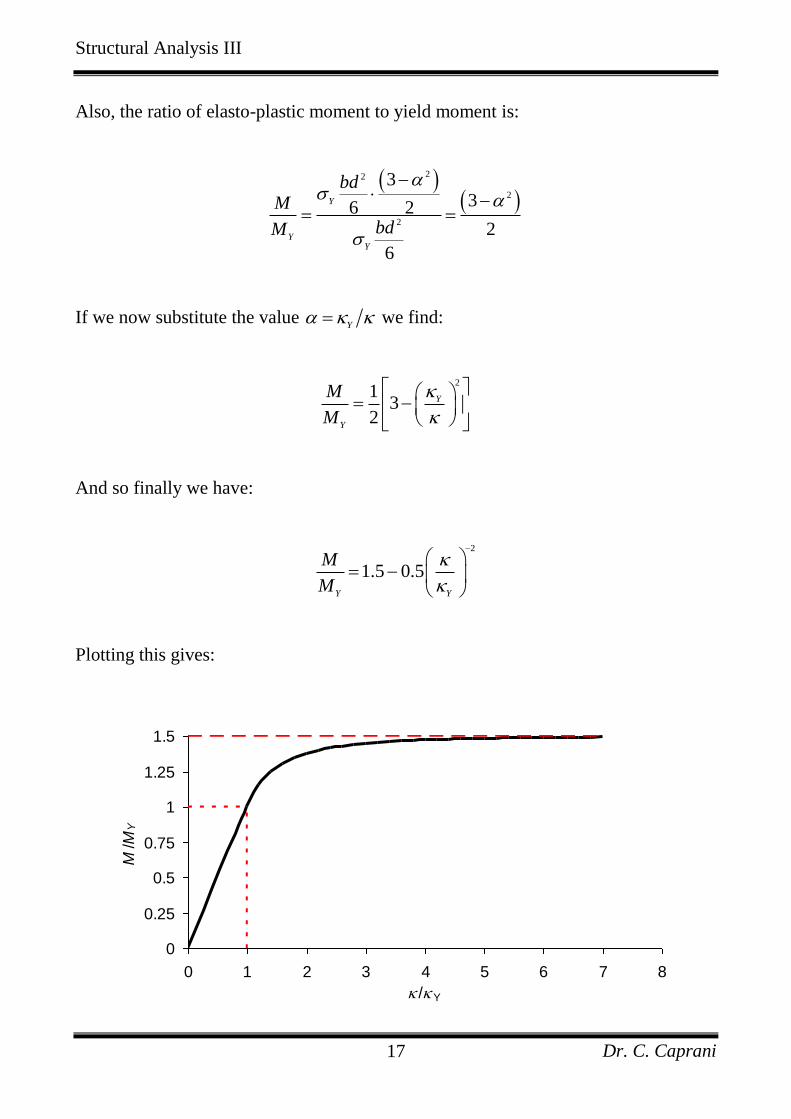
Also, the ratio of elasto-plastic moment to yield moment is:
22
2
2
336 2
2
6
Y
YY
bdM
bdM
If we now substitute the value Y
we find:
2
13
2
Y
Y
M
M
And so finally we have:
2
1.5 0.5Y Y
M
M
Plotting this gives:
0
0.25
0.5
0.75
1
1.25
1.5
0 1 2 3 4 5 6 7 8
/Y
M/M
Y
Structural Analysis III
Dr. C. Caprani 18
There are some important observations to be made from this graph:
To reach the plastic moment capacity of the section requires large curvatures. Thus
the section must be ductile.
The full cross-section plasticity associated with the plastic moment capacity of a
section can only be reached at infinite curvature (or infinite strain). Since this is
impossible, we realise that the full plastic moment capacity is unobtainable.
To demonstrate this last point, that the idea of the plastic moment capacity of section
is still useful, we examine it further. Firstly we note that strain hardening in mild steel
begins to occur at a strain of about 10 Y . At this strain, the corresponding moment
ratio is:
2
1.5 0.5 10 1.495Y
M
M
Since this is about 99.7% of the plastic moment capacity, we see that the plastic
moment capacity of a section is a good approximation of the section’s capacity.
These calculations are based on a ductility ratio of 10. This is about the level of
ductility a section requires to be of use in any plastic collapse analysis.
Lastly, for other cross-section shapes we have the moment-curvature relations shown
in the following figure.
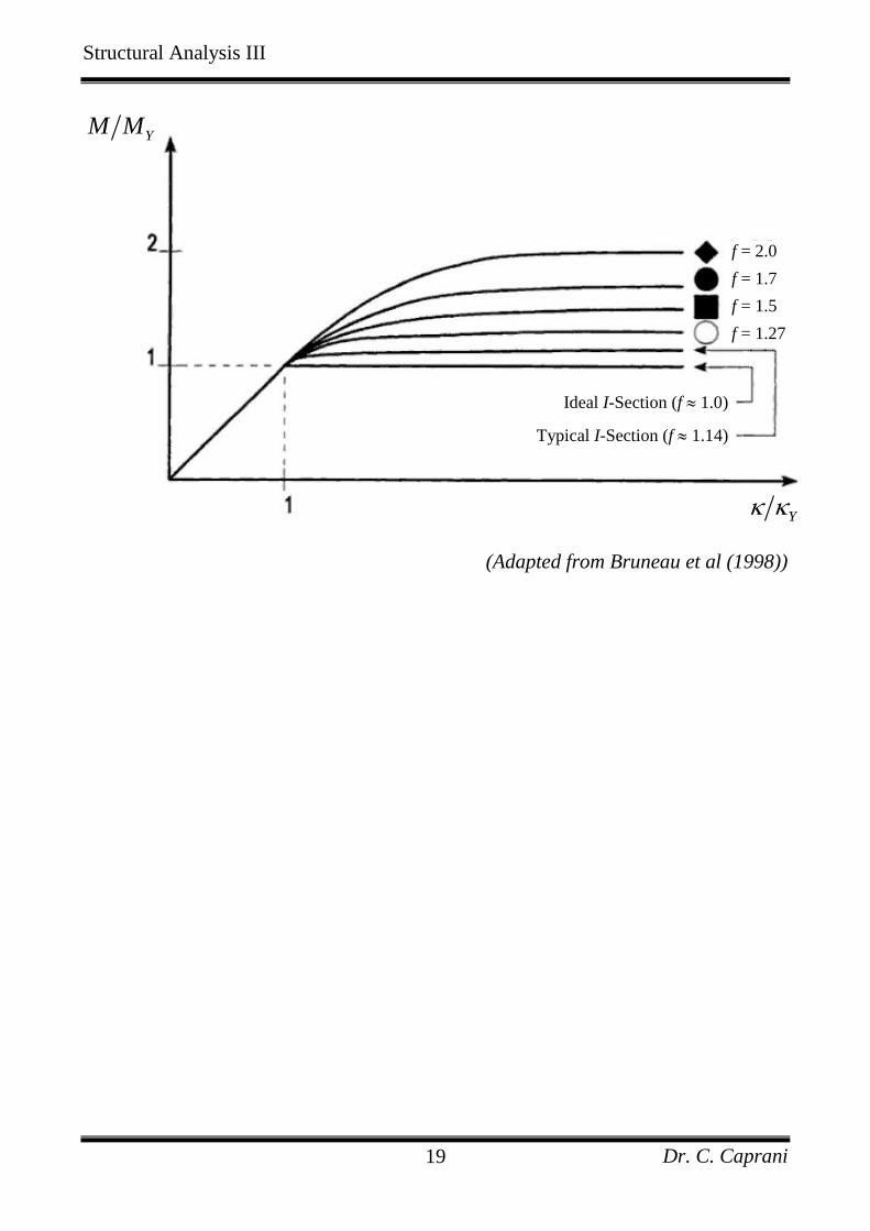
Structural Analysis III
Dr. C. Caprani 19
YM M
f = 2.0
f = 1.7
f = 1.5
f = 1.27
Ideal I-Section (f 1.0)
Typical I-Section (f 1.14)
Y
(Adapted from Bruneau et al (1998))

Structural Analysis III
Dr. C. Caprani 20
Effect of Axial Force on the Plastic Moment Capacity
Thus far the cross sections considered are only carrying moment. In the presence of
axial force, clearly some material must be given over to carry the axial force and so is
not available to carry moment, reducing the capacity of the section. Further, it should
be apparent that the moment capacity of the section therefore depends on the amount
of axial load being carried.
Considering a compression load as positive, more of the section will be in
compression and so the neutral axis will drop. If we consider the moment and axial
force separately, we have:
This is more easily analyzed if we consider decompose the stress diagram into an
equivalent bending component and a fictitious axial stress of 2 Y as shown below:
Structural Analysis III
Dr. C. Caprani 21
The axial force corresponding to this state is:
2 YP b d
If we label the plastic ‘squash load’ of the section as:
C YP bd
Then we have:
2 CP P
Next, the collapse moment that this section offers, PCM , is got by taking moments
about the centroidal axis:
1
2PC PM M P d
Using, 2
4P Y
bdM and the expression for P above:
2
22
12
4 2
1 44
PC Y Y
Y
bdM b d d
bd
Giving,
Structural Analysis III
Dr. C. Caprani 22
21 4PC PM M
Noting that 2 CP P from earlier, we now have:
2
21 2 1PC
P C
M P
M P
Thus the interaction equation is:
2
1PC
P C
M P
M P
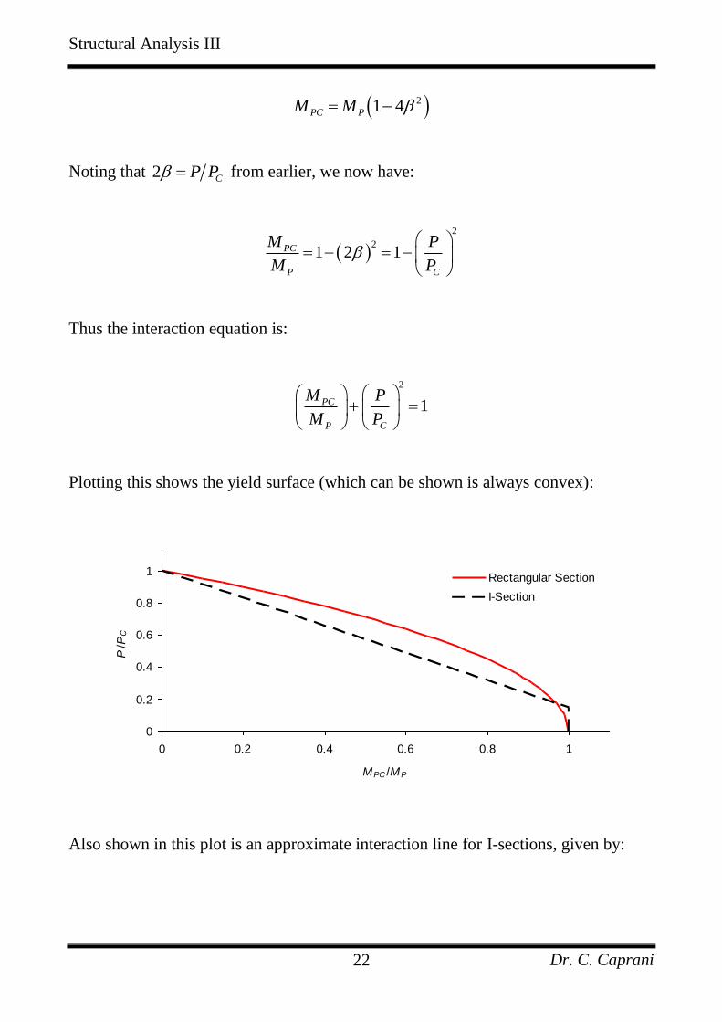
Plotting this shows the yield surface (which can be shown is always convex):
0
0.2
0.4
0.6
0.8
1
0 0.2 0.4 0.6 0.8 1
MPC /MP
P/P
C
Rectangular Section
I-Section
Also shown in this plot is an approximate interaction line for I-sections, given by:
Structural Analysis III
Dr. C. Caprani 23
0.15: 1.18 1
0.15: 1.0
PC
C P C
PC
C P
P M P
P M P
P M
P M
This says that for I-sections with an axial load of less than 15% of the squash load,
the full plastic moment capacity may be still considered. This is because the web
carries the axial load whilst contributing little to the moment capacity of the section.
Shear force can also reduce the plastic moment capacity of a section in some cases. In
the presence of axial and shear, a three dimensional failure surface is required.
Structural Analysis III
Dr. C. Caprani 24
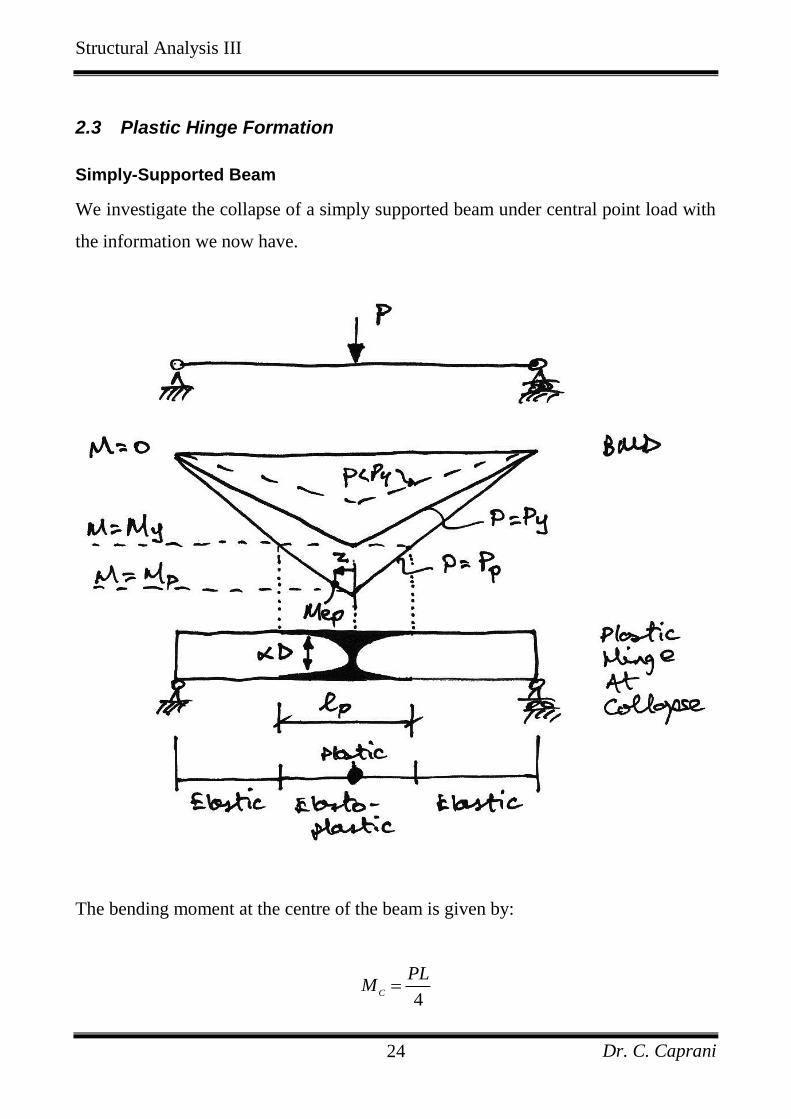
2.3 Plastic Hinge Formation
Simply-Supported Beam
We investigate the collapse of a simply supported beam under central point load with
the information we now have.
The bending moment at the centre of the beam is given by:
4
C
PLM
Structural Analysis III
Dr. C. Caprani 25
Therefore the load at which yield first occurs is:
4
4
Y
C Y
Y
Y
P LM M
MP
L
Collapse of this beam occurs when the plastic hinge forms at the centre of the beam,
since the extra hinge turns the statically determinate beam into a mechanism. The
collapse load occurs when the moment at the centre reaches the plastic moment
capacity:
4
4
P
C P
P
P
P LM M
MP
L
The ratio collapse to yield load is:
4
4
P P P
Y Y Y
P M L M
P M L M
But since,
P
Y
M Sf
M Z
The ratio is just the shape factor of the section. This is a general result: the ratio of
collapse load to first yield load is the shape factor of the member, for statically
determinate prismatic structures.
Structural Analysis III
Dr. C. Caprani 26
Shape of the Plastic Hinge
We are also interested in the plastic hinge, and the zone of elasto-plastic bending. As
can be seen from the diagram, the plastic material zones extend from the centre out to
the point where the moment equals the yield moment.
Using similar triangles from the bending moment diagram at collapse, we see that:
2
P P Y P EP
p
M M M M M
L l z
In which EP
M is the elasto-plastic moment at a distance z from the plastic hinge, and
where 2
pl
z , where p
l is the total length of the plastic region.
Equating the first two equations gives:
1
1 1Y
p P Y
P P
L Ml M M L L
M M f
And so for a beam with a rectangular cross section ( 1.5f ) the plastic hinge extends
for a length:
1
11.5 3
p
Ll L
Lastly, the shape of the hinge follows from the first and third equation:
Structural Analysis III
Dr. C. Caprani 27
2
1
2
11
2
P P EP
P EP
P
EP
P
M M M
L z
zM M
L M
z M
L M
From our expressions for the elasto-plastic and plastic moments, we have:
2 2
2
2
2
6 1 2 311
2 4
1 2 11 3
2 3 2
6
Y
Y
bdz
L bd
z
L
This shows that the plastic region has a parabolic profile, and confirms that the total
length of the hinge, 2p
l z , is 3L at the location where 1.0 .
Using a similar form of analysis, we can show that under a UDL the plastic hinge has
a linear profile given by 2 3z L and that its length is 3L .
Structural Analysis III
Dr. C. Caprani 28
3. Methods of Plastic Analysis
3.1 Introduction
There are three main approaches for performing a plastic analysis:
The Incremental Method
This is probably the most obvious approach: the loads on the structure are
incremented until the first plastic hinge forms. This continues until sufficient hinges
have formed to collapse the structure. This is a labour-intensive, ‘brute-force’,
approach, but one that is most readily suited for computer implementation.
The Equilibrium (or Statical) Method
In this method, free and reactant bending moment diagrams are drawn. These
diagrams are overlaid to identify the likely locations of plastic hinges. This method
therefore satisfies the equilibrium criterion first leaving the two remaining criterion to
derived therefrom.
The Kinematic (or Mechanism) Method
In this method, a collapse mechanism is first postulated. Virtual work equations are
then written for this collapse state, allowing the calculations of the collapse bending
moment diagram. This method satisfies the mechanism condition first, leaving the
remaining two criteria to be derived therefrom.
We will concentrate mainly on the Kinematic Method, but introduce now the
Incremental Method to illustrate the main concepts.
Structural Analysis III
Dr. C. Caprani 29
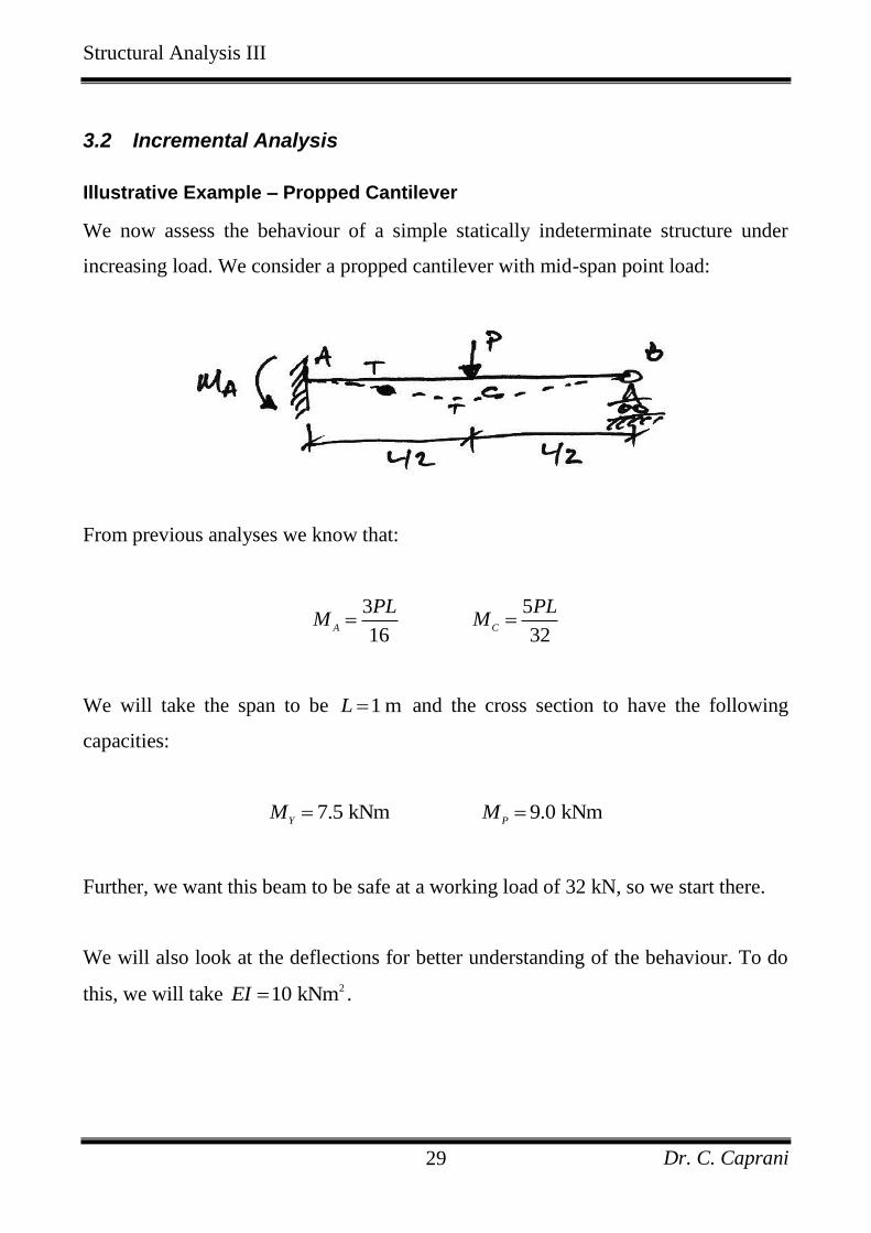
3.2 Incremental Analysis
Illustrative Example – Propped Cantilever
We now assess the behaviour of a simple statically indeterminate structure under
increasing load. We consider a propped cantilever with mid-span point load:
From previous analyses we know that:
3 5
16 32A C
PL PLM M
We will take the span to be 1 mL and the cross section to have the following
capacities:
7.5 kNm 9.0 kNmY P
M M
Further, we want this beam to be safe at a working load of 32 kN, so we start there.
We will also look at the deflections for better understanding of the behaviour. To do
this, we will take 210 kNmEI .
Structural Analysis III
Dr. C. Caprani 30
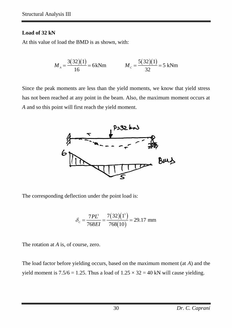
Load of 32 kN
At this value of load the BMD is as shown, with:
3 32 1 5 32 1
6kNm 5 kNm16 32
A CM M
Since the peak moments are less than the yield moments, we know that yield stress
has not been reached at any point in the beam. Also, the maximum moment occurs at
A and so this point will first reach the yield moment.
The corresponding deflection under the point load is:
33 7 32 1729.17 mm
768 768 10C
PL
EI
The rotation at A is, of course, zero.
The load factor before yielding occurs, based on the maximum moment (at A) and the
yield moment is 7.5/6 = 1.25. Thus a load of 1.25 × 32 = 40 kN will cause yielding.
Structural Analysis III
Dr. C. Caprani 31
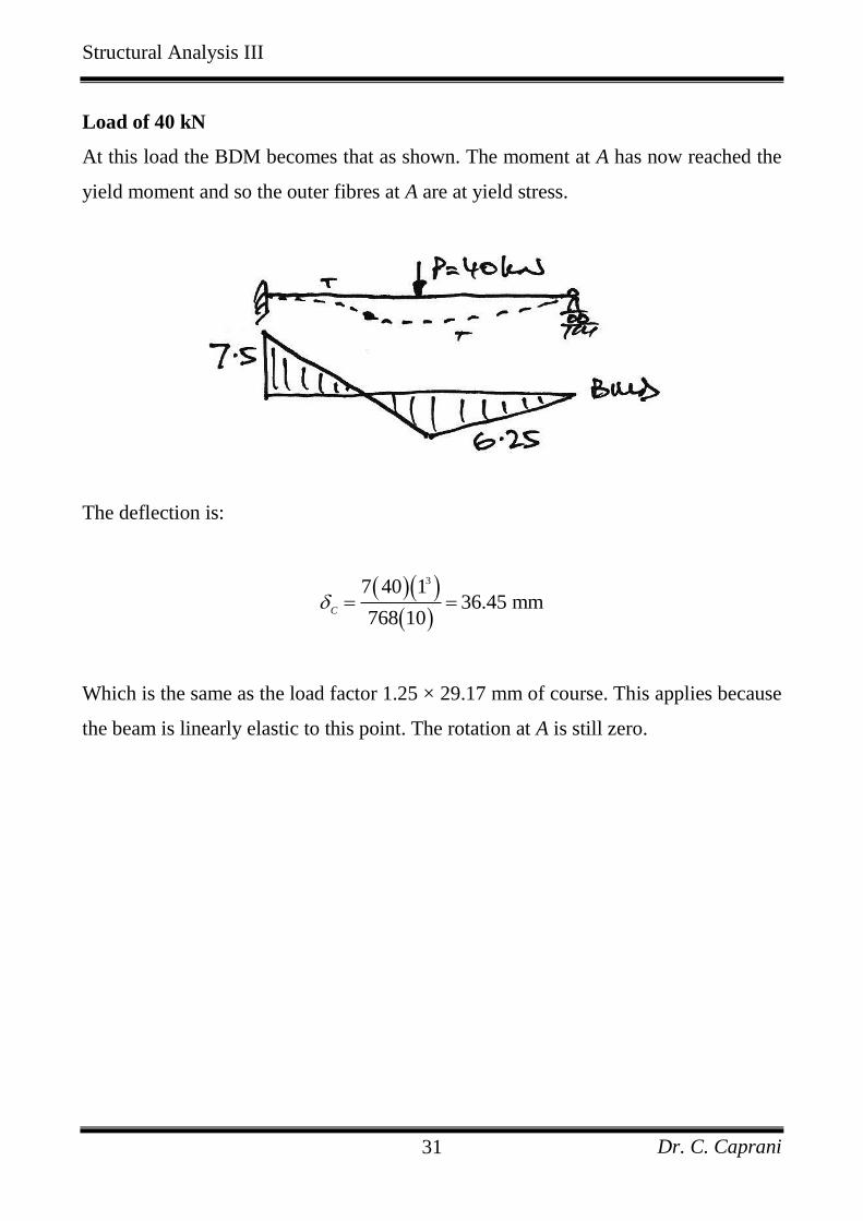
Load of 40 kN
At this load the BDM becomes that as shown. The moment at A has now reached the
yield moment and so the outer fibres at A are at yield stress.
The deflection is:
37 40 136.45 mm
768 10C
Which is the same as the load factor 1.25 × 29.17 mm of course. This applies because
the beam is linearly elastic to this point. The rotation at A is still zero.
Structural Analysis III
Dr. C. Caprani 32
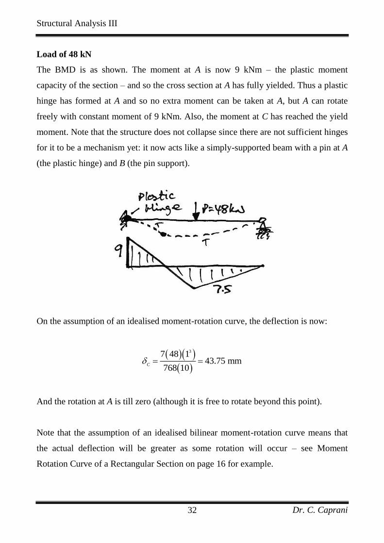
Load of 48 kN
The BMD is as shown. The moment at A is now 9 kNm – the plastic moment
capacity of the section – and so the cross section at A has fully yielded. Thus a plastic
hinge has formed at A and so no extra moment can be taken at A, but A can rotate
freely with constant moment of 9 kNm. Also, the moment at C has reached the yield
moment. Note that the structure does not collapse since there are not sufficient hinges
for it to be a mechanism yet: it now acts like a simply-supported beam with a pin at A
(the plastic hinge) and B (the pin support).
On the assumption of an idealised moment-rotation curve, the deflection is now:
37 48 143.75 mm
768 10C
And the rotation at A is till zero (although it is free to rotate beyond this point).
Note that the assumption of an idealised bilinear moment-rotation curve means that
the actual deflection will be greater as some rotation will occur – see Moment
Rotation Curve of a Rectangular Section on page 16 for example.
Structural Analysis III
Dr. C. Caprani 33
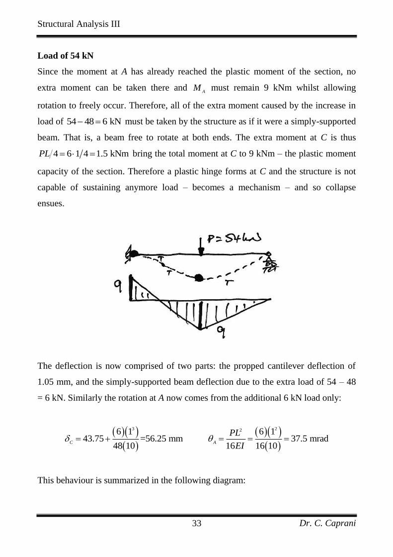
Load of 54 kN
Since the moment at A has already reached the plastic moment of the section, no
extra moment can be taken there and A
M must remain 9 kNm whilst allowing
rotation to freely occur. Therefore, all of the extra moment caused by the increase in
load of 54 48 6 kN must be taken by the structure as if it were a simply-supported
beam. That is, a beam free to rotate at both ends. The extra moment at C is thus
4 6 1 4 1.5 kNmPL bring the total moment at C to 9 kNm – the plastic moment
capacity of the section. Therefore a plastic hinge forms at C and the structure is not
capable of sustaining anymore load – becomes a mechanism – and so collapse
ensues.
The deflection is now comprised of two parts: the propped cantilever deflection of
1.05 mm, and the simply-supported beam deflection due to the extra load of 54 – 48
= 6 kN. Similarly the rotation at A now comes from the additional 6 kN load only:
3 226 1 6 143.75 =56.25 mm 37.5 mrad
48 10 16 16 10C A
PL
EI
This behaviour is summarized in the following diagram:
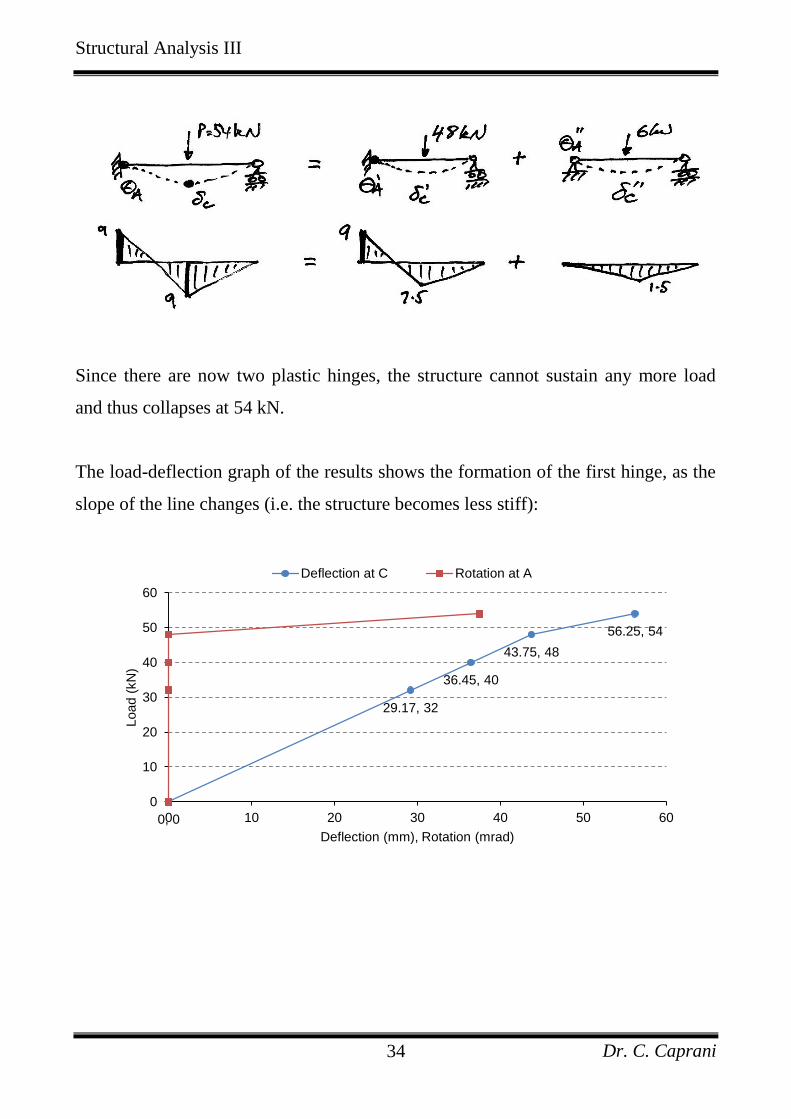
Structural Analysis III
Dr. C. Caprani 34
Since there are now two plastic hinges, the structure cannot sustain any more load
and thus collapses at 54 kN.
The load-deflection graph of the results shows the formation of the first hinge, as the
slope of the line changes (i.e. the structure becomes less stiff):
0, 0
29.17, 32
36.45, 40
43.75, 48
56.25, 54
0
10
20
30
40
50
60
0 10 20 30 40 50 60
Load (
kN
)
Deflection (mm), Rotation (mrad)
Deflection at C Rotation at A
Structural Analysis III
Dr. C. Caprani 35
Discussion
There are several things to note from this analysis:
1. The actual load carried by the beam is 54 kN, greater than the load at which yield
first occurs, 40 kN, the elastic limit. This difference of 35% represents the extra
capacity of the structure over the elastic capacity, so to ignore it would be very
inefficient.
2. At the end of the analysis 9 kNmA C
M M and so 1A C
M M . Since for an
elastic analysis 3 16 5 32 1.2A C
M M PL PL , it is evident that our analysis
is not an elastic analysis and so is a plastic analysis.
3. The height of the free bending moment diagram was 4PL throughout, as
required by equilibrium – only the height of the reactant bending moment diagram
varied. This is the basis of the Equilibrium Method.
4. At the point of collapse we had 4 reactions and 2 plastic hinges giving a statical
indeterminacy of 3 4 2 3 1R C which is a mechanism and so collapse
occurs.
5. The load can only increase from 48 kN to 54 kN once the cross section at A has
sufficient ductility to allow it rotate thereby allowing the extra load to be taken at
C. If there was not sufficient ductility there may have a brittle-type catastrophic
failure at A resulting in the beam failing by rotating about B before the full plastic
capacity of the structure is realized. Therefore it is only by having sufficient
ductility that a plastic analysis can be used.
Some of these points are general for any plastic analysis and these generalities are
known as the Theorems of Plastic Analysis. However, before looking at these
theorems we need a simpler way of analysing for the collapse of structures: the
Incremental Method just used clearly works, but is very laborious.
Structural Analysis III
Dr. C. Caprani 36
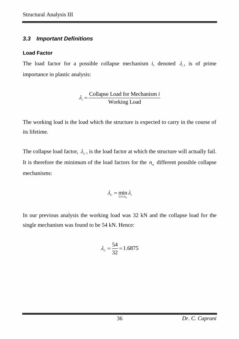
3.3 Important Definitions
Load Factor
The load factor for a possible collapse mechanism i, denoted i , is of prime
importance in plastic analysis:
Collapse Load for Mechanism
Working Loadi
i
The working load is the load which the structure is expected to carry in the course of
its lifetime.
The collapse load factor, C , is the load factor at which the structure will actually fail.
It is therefore the minimum of the load factors for the m
n different possible collapse
mechanisms:
m1
minC i
i n
In our previous analysis the working load was 32 kN and the collapse load for the
single mechanism was found to be 54 kN. Hence:
54
1.687532
C
Structural Analysis III
Dr. C. Caprani 37
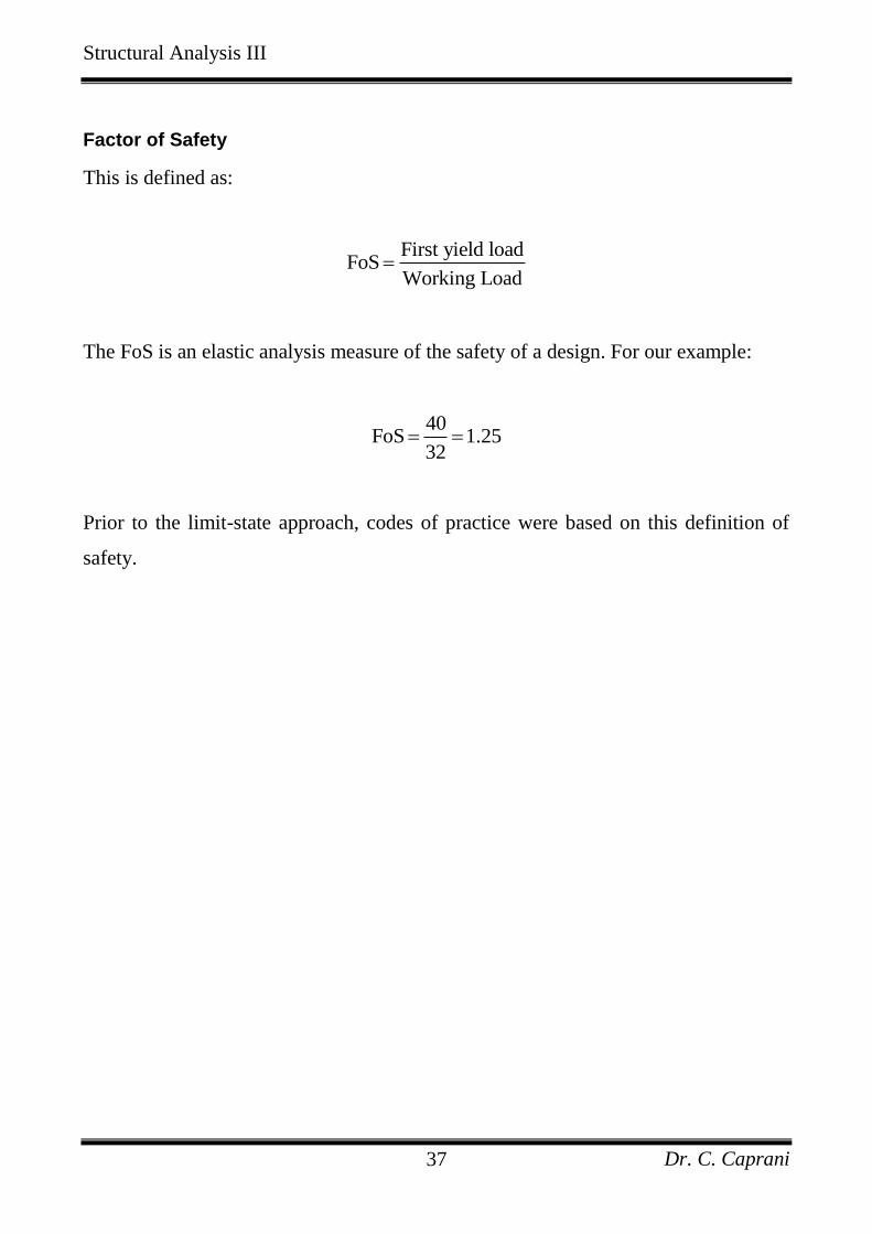
Factor of Safety
This is defined as:
First yield load
FoSWorking Load
The FoS is an elastic analysis measure of the safety of a design. For our example:
40
FoS 1.2532
Prior to the limit-state approach, codes of practice were based on this definition of
safety.
Structural Analysis III
Dr. C. Caprani 38
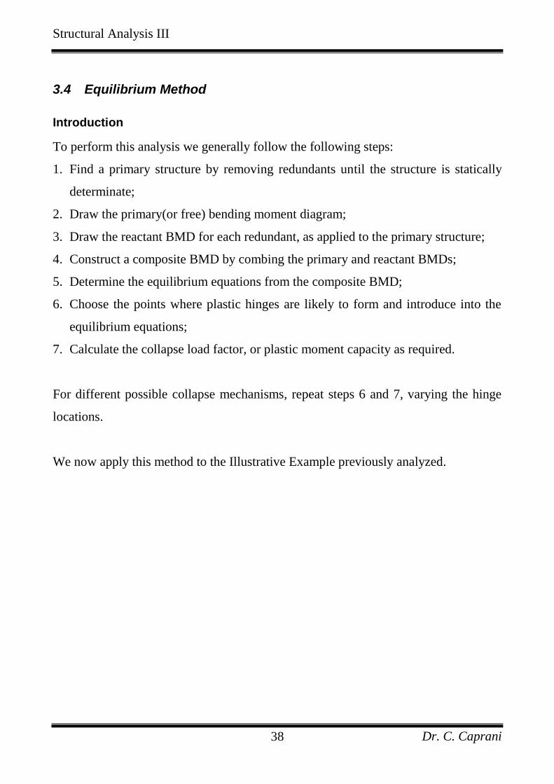
3.4 Equilibrium Method
Introduction
To perform this analysis we generally follow the following steps:
1. Find a primary structure by removing redundants until the structure is statically
determinate;
2. Draw the primary(or free) bending moment diagram;
3. Draw the reactant BMD for each redundant, as applied to the primary structure;
4. Construct a composite BMD by combing the primary and reactant BMDs;
5. Determine the equilibrium equations from the composite BMD;
6. Choose the points where plastic hinges are likely to form and introduce into the
equilibrium equations;
7. Calculate the collapse load factor, or plastic moment capacity as required.
For different possible collapse mechanisms, repeat steps 6 and 7, varying the hinge
locations.
We now apply this method to the Illustrative Example previously analyzed.
Structural Analysis III
Dr. C. Caprani 39
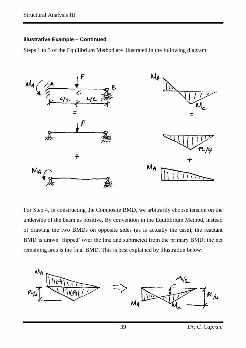
Illustrative Example – Continued
Steps 1 to 3 of the Equilibrium Method are illustrated in the following diagram:
For Step 4, in constructing the Composite BMD, we arbitrarily choose tension on the
underside of the beam as positive. By convention in the Equilibrium Method, instead
of drawing the two BMDs on opposite sides (as is actually the case), the reactant
BMD is drawn ‘flipped’ over the line and subtracted from the primary BMD: the net
remaining area is the final BMD. This is best explained by illustration below:
Structural Analysis III
Dr. C. Caprani 40
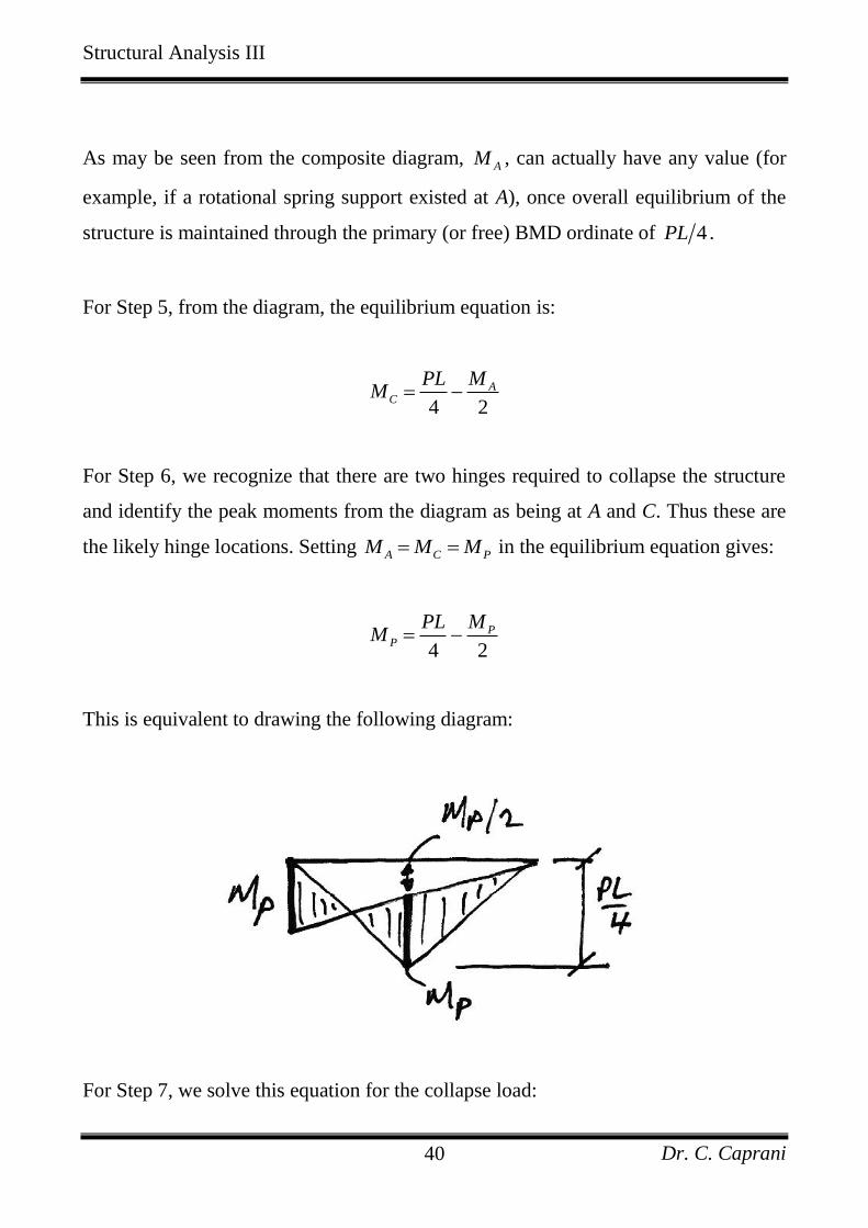
As may be seen from the composite diagram, AM , can actually have any value (for
example, if a rotational spring support existed at A), once overall equilibrium of the
structure is maintained through the primary (or free) BMD ordinate of 4PL .
For Step 5, from the diagram, the equilibrium equation is:
4 2
AC
PL MM
For Step 6, we recognize that there are two hinges required to collapse the structure
and identify the peak moments from the diagram as being at A and C. Thus these are
the likely hinge locations. Setting A C PM M M in the equilibrium equation gives:
4 2
PP
PL MM
This is equivalent to drawing the following diagram:
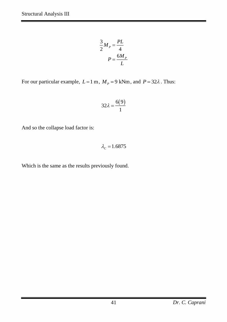
For Step 7, we solve this equation for the collapse load:
Structural Analysis III
Dr. C. Caprani 41
3
2 4
6
P
P
PLM
MP
L
For our particular example, 1 mL , 9 kNmPM , and 32P . Thus:
6 9
321
And so the collapse load factor is:
1.6875C
Which is the same as the results previously found.
Structural Analysis III
Dr. C. Caprani 42
3.5 Kinematic Method Using Virtual Work
Introduction
Probably the easiest way to carry out a plastic analysis is through the Kinematic
Method using virtual work. To do this we allow the presumed shape at collapse to be
the compatible displacement set, and the external loading and internal bending
moments to be the equilibrium set. We can then equate external and internal virtual
work, and solve for the collapse load factor for that supposed mechanism.
Remember:
Equilibrium set: the internal bending moments at collapse;
Compatible set: the virtual collapsed configuration (see below).
Note that in the actual collapse configuration the members will have elastic
deformation in between the plastic hinges. However, since a virtual displacement
does not have to be real, only compatible, we will choose to ignore the elastic
deformations between plastic hinges, and take the members to be straight between
them.
Structural Analysis III
Dr. C. Caprani 43
Illustrative Example – Continued
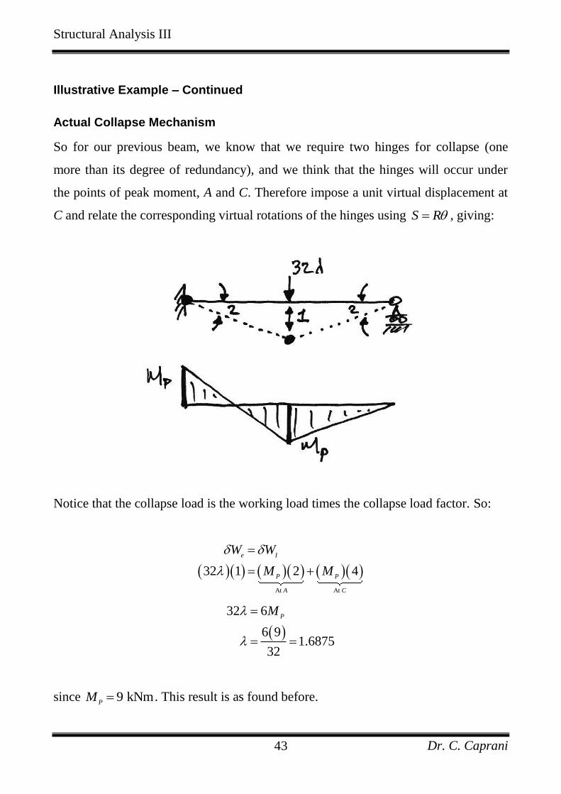
Actual Collapse Mechanism
So for our previous beam, we know that we require two hinges for collapse (one
more than its degree of redundancy), and we think that the hinges will occur under
the points of peak moment, A and C. Therefore impose a unit virtual displacement at
C and relate the corresponding virtual rotations of the hinges using S R , giving:
Notice that the collapse load is the working load times the collapse load factor. So:
At At
32 1 2 4
e I
P P
A C
W W
M M
32 6
6 91.6875
32
PM
since 9 kNmP
M . This result is as found before.
Structural Analysis III
Dr. C. Caprani 44
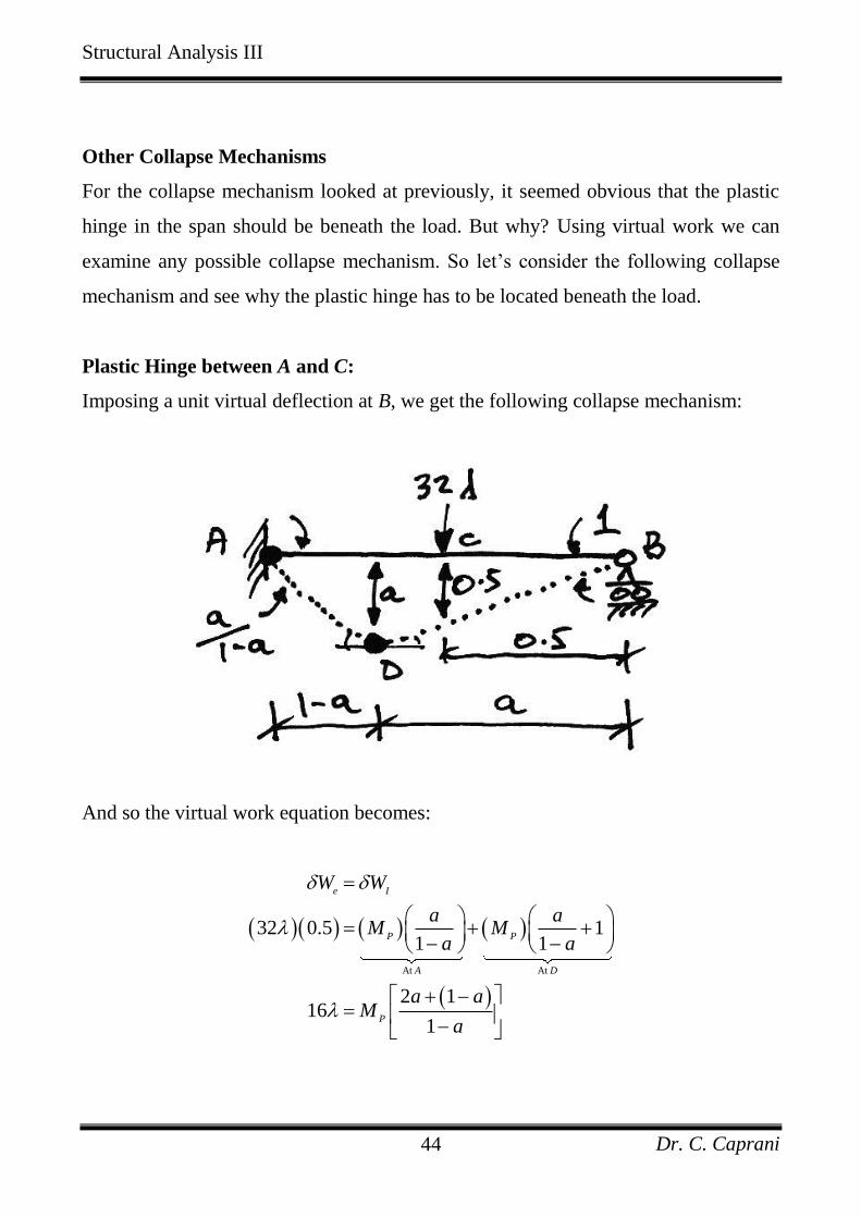
Other Collapse Mechanisms
For the collapse mechanism looked at previously, it seemed obvious that the plastic
hinge in the span should be beneath the load. But why? Using virtual work we can
examine any possible collapse mechanism. So let’s consider the following collapse
mechanism and see why the plastic hinge has to be located beneath the load.
Plastic Hinge between A and C:
Imposing a unit virtual deflection at B, we get the following collapse mechanism:
And so the virtual work equation becomes:
At At
32 0.5 11 1
2 116
1
e I
P P
A D
P
W W
a aM M
a a
a aM
a
Structural Analysis III
Dr. C. Caprani 45
And since 9 kNmP
M :
1 0.5
9 1
16 1a
a
a
Eq. (1)
And so we see that the collapse load factor for this mechanism depends on the
position of the plastic hinge in the span.
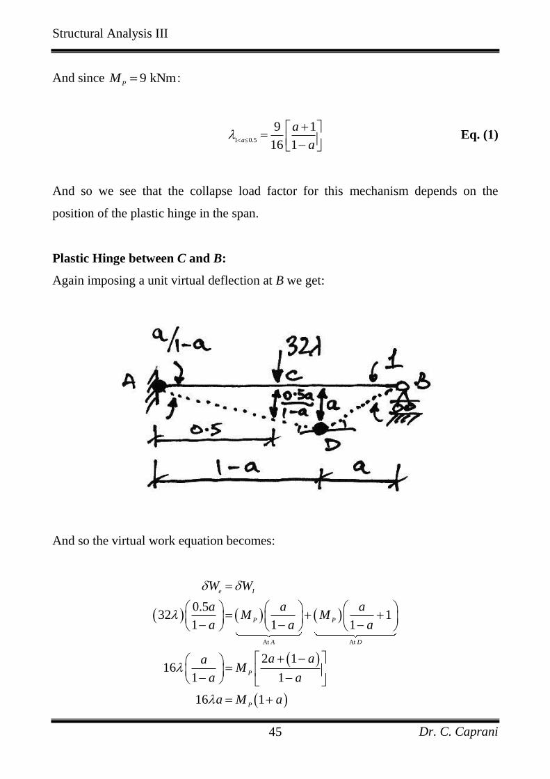
Plastic Hinge between C and B:
Again imposing a unit virtual deflection at B we get:
And so the virtual work equation becomes:
At At
0.532 1
1 1 1
2 116
1 1
16 1
e I
P P
A D
P
P
W W
a a aM M
a a a
a aaM
a a
a M a
Structural Analysis III
Dr. C. Caprani 46
Using 9 kNmP
M :
0.5 0
9 1
16a
a
a
Eq. (2)
And again we see that the load factor depends on the position of the hinge.
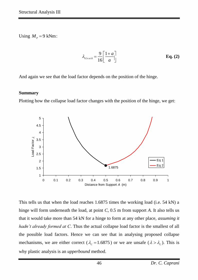
Summary
Plotting how the collapse load factor changes with the position of the hinge, we get:
1.6875
1
1.5
2
2.5
3
3.5
4
4.5
5
0 0.1 0.2 0.3 0.4 0.5 0.6 0.7 0.8 0.9 1
Distance from Support A (m)
Load F
acto
r
Eq 1
Eq 2
This tells us that when the load reaches 1.6875 times the working load (i.e. 54 kN) a
hinge will form underneath the load, at point C, 0.5 m from support A. It also tells us
that it would take more than 54 kN for a hinge to form at any other place, assuming it
hadn’t already formed at C. Thus the actual collapse load factor is the smallest of all
the possible load factors. Hence we can see that in analysing proposed collapse
mechanisms, we are either correct ( 1.6875C ) or we are unsafe (
C ). This is
why plastic analysis is an upperbound method.
Structural Analysis III
Dr. C. Caprani 47
3.6 Types of Plastic Collapse
Complete Collapse
In the cases considered so far, collapse occurred when a hinge occurred for each of
the number of redundants, r, (making it a determinate structure) with an extra hinge
for collapse. Thus the number of hinges formed, 1h r (the degree of
indeterminacy plus one).
Partial Collapse
This occurs when 1h r , but a collapse mechanism, of a localised section of the
structure can form. A common example is a single span of a continuous beam.
Over-Complete Collapse
For some frames, two (or more) possible collapse mechanisms are found ( 1h r )
with the actual collapse load factor. Therefore they can be combined to form another
collapse mechanism with the same collapse load factor, but with an increased number
of hinges, 1h r .
Structural Analysis III
Dr. C. Caprani 48
4. Theorems of Plastic Analysis
4.1 Criteria
In Plastic Analysis to identify the correct load factor, there are three criteria of
importance:
1. Equilibrium: the internal bending moments must be in equilibrium with the
external loading.
2. Mechanism: at collapse the structure, or a part of, can deform as a mechanism.
3. Yield: no point in the structure can have a moment greater than the plastic
moment capacity of the section it is applied to.
Based on these criteria, we have the following theorems.
Structural Analysis III
Dr. C. Caprani 49
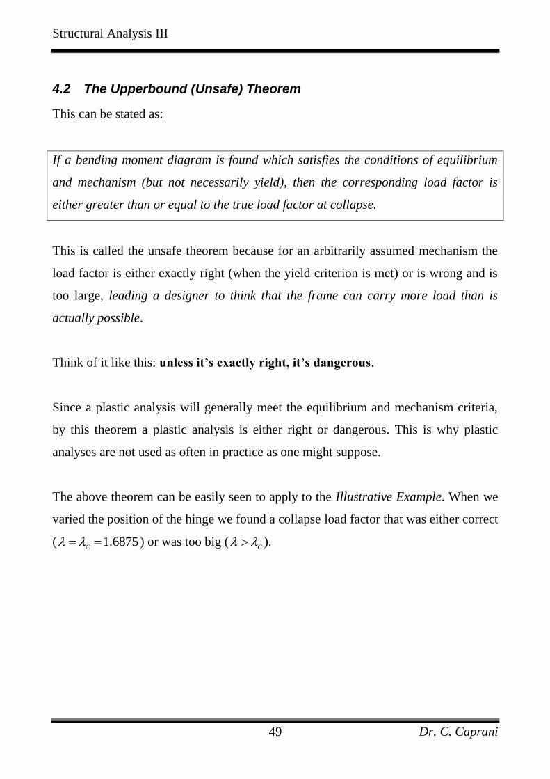
4.2 The Upperbound (Unsafe) Theorem
This can be stated as:
If a bending moment diagram is found which satisfies the conditions of equilibrium
and mechanism (but not necessarily yield), then the corresponding load factor is
either greater than or equal to the true load factor at collapse.
This is called the unsafe theorem because for an arbitrarily assumed mechanism the
load factor is either exactly right (when the yield criterion is met) or is wrong and is
too large, leading a designer to think that the frame can carry more load than is
actually possible.
Think of it like this: unless it’s exactly right, it’s dangerous.
Since a plastic analysis will generally meet the equilibrium and mechanism criteria,
by this theorem a plastic analysis is either right or dangerous. This is why plastic
analyses are not used as often in practice as one might suppose.
The above theorem can be easily seen to apply to the Illustrative Example. When we
varied the position of the hinge we found a collapse load factor that was either correct
( 1.6875C
) or was too big (C
).
Structural Analysis III
Dr. C. Caprani 50
4.3 The Lowerbound (Safe) Theorem
This can be stated as:
If a bending moment diagram is found which satisfies the conditions of equilibrium
and yield (but not necessarily that of mechanism), then the corresponding load factor
is either less than or equal to the true load factor at collapse.
This is a safe theorem because the load factor will be less than (or at best equal to)
the collapse load factor once equilibrium and yield criteria are met leading the
designer to think that the structure can carry less than or equal to its actual capacity.
Think of it like this: it’s either wrong and safe or right and safe.
Since an elastic analysis will always meet equilibrium and yield conditions, an elastic
analysis will always be safe. This is the main reason that it is elastic analysis that is
used, in spite of the significant extra capacity that plastic analysis offers.
Structural Analysis III
Dr. C. Caprani 51
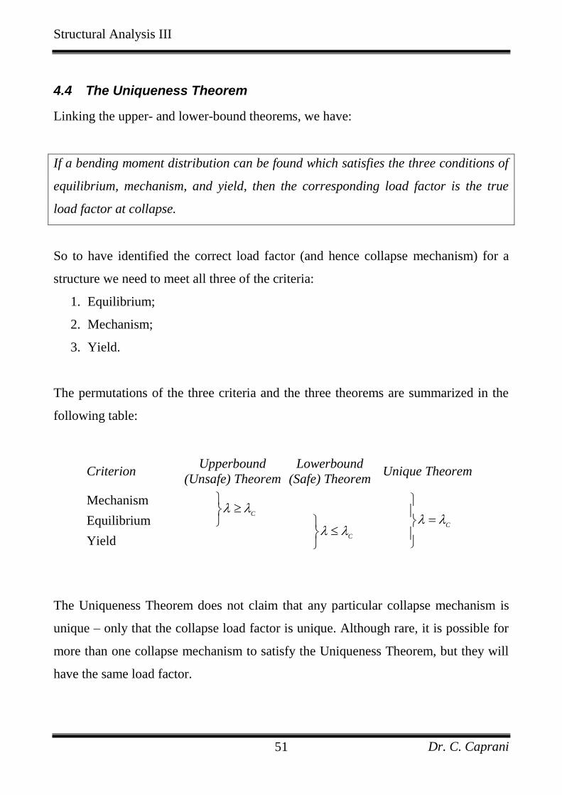
4.4 The Uniqueness Theorem
Linking the upper- and lower-bound theorems, we have:
If a bending moment distribution can be found which satisfies the three conditions of
equilibrium, mechanism, and yield, then the corresponding load factor is the true
load factor at collapse.
So to have identified the correct load factor (and hence collapse mechanism) for a
structure we need to meet all three of the criteria:
1. Equilibrium;
2. Mechanism;
3. Yield.
The permutations of the three criteria and the three theorems are summarized in the
following table:
Criterion Upperbound
(Unsafe) Theorem
Lowerbound
(Safe) Theorem Unique Theorem
Mechanism C
C
Equilibrium C
Yield
The Uniqueness Theorem does not claim that any particular collapse mechanism is
unique – only that the collapse load factor is unique. Although rare, it is possible for
more than one collapse mechanism to satisfy the Uniqueness Theorem, but they will
have the same load factor.
Structural Analysis III
Dr. C. Caprani 52
4.5 Corollaries of the Theorems
Some other results immediately apparent from the theorems are the following:
1. If the collapse loads are determined for all possible mechanisms, then the actual
collapse load will be the lowest of these (Upperbound Theorem);
2. The collapse load of a structure cannot be decreased by increasing the strength of
any part of it (Lowerbound Theorem);
3. The collapse load of a structure cannot be increased by decreasing the strength of
any part of it (Upperbound Theorem);
4. The collapse load is independent of initial stresses and the order in which the
plastic hinges form (Uniqueness Theorem);
The first point above is the basis for using virtual work in plastic analysis. However,
in doing so, it is essential that the designer considers the actual collapse more. To not
do so would lead to an unsafe design by the Upperbound Theorem.
Structural Analysis III
Dr. C. Caprani 53
4.6 Application of the Theorems
Illustrative Example – Continued
Plastic Hinge Under the Load
We discovered previously that the collapse load factor was 1.6875 and this occurred
when the hinge was under the point load. Therefore, this collapse mechanism should
meet all three criteria of the Uniqueness Theorem:
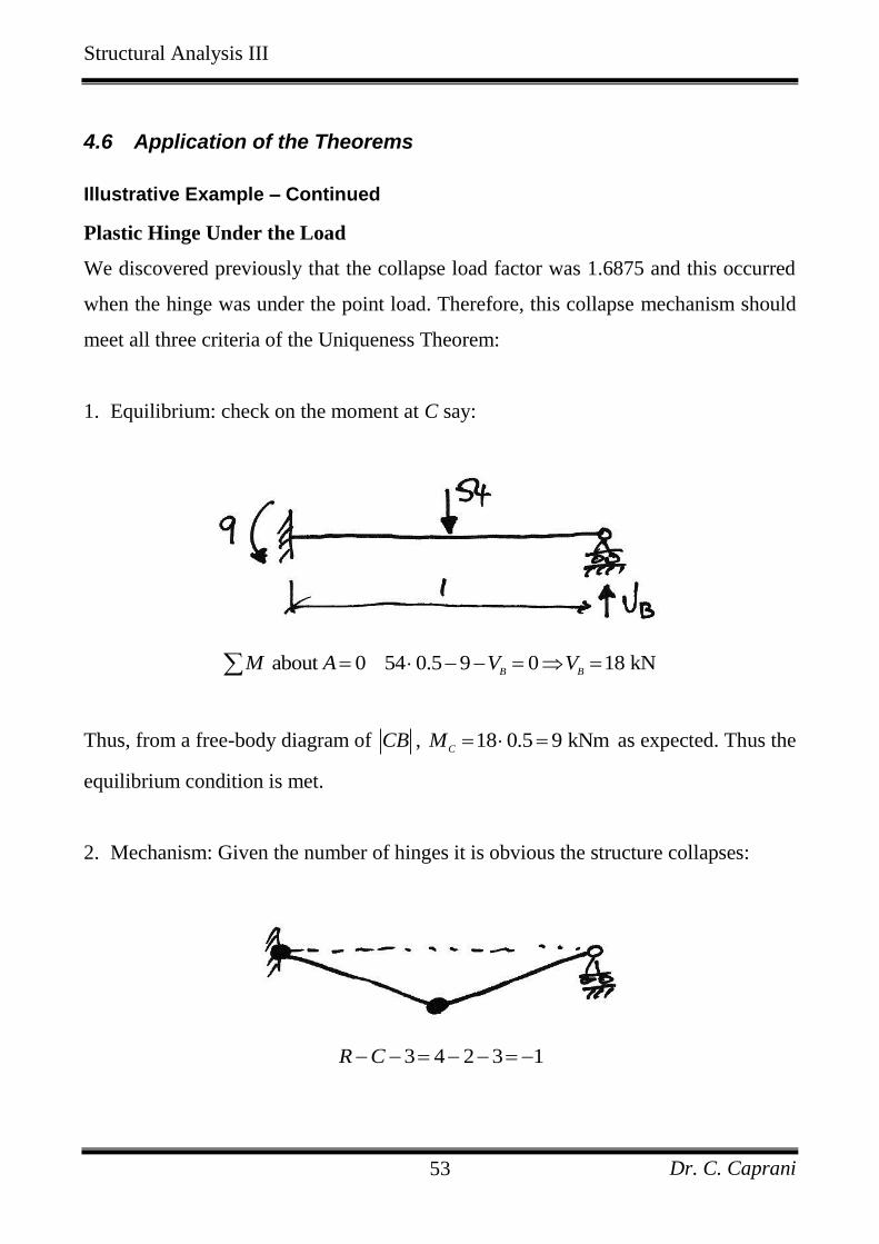
1. Equilibrium: check on the moment at C say:
about 0 54 0.5 9 0 18 kNB B
M A V V
Thus, from a free-body diagram of CB , 18 0.5 9 kNmC
M as expected. Thus the
equilibrium condition is met.
2. Mechanism: Given the number of hinges it is obvious the structure collapses:
3 4 2 3 1R C
Structural Analysis III
Dr. C. Caprani 54
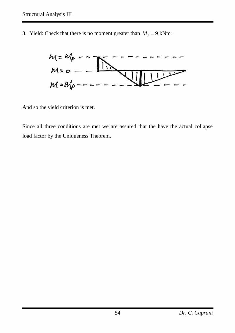
3. Yield: Check that there is no moment greater than 9 kNmP
M :
And so the yield criterion is met.
Since all three conditions are met we are assured that the have the actual collapse
load factor by the Uniqueness Theorem.
Structural Analysis III
Dr. C. Caprani 55
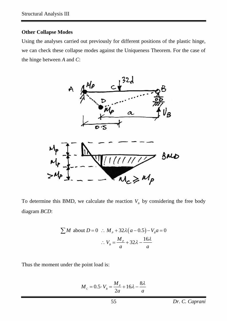
Other Collapse Modes
Using the analyses carried out previously for different positions of the plastic hinge,
we can check these collapse modes against the Uniqueness Theorem. For the case of
the hinge between A and C:
To determine this BMD, we calculate the reaction B
V by considering the free body
diagram BCD:
about 0 32 0.5 0
1632
P B
P
B
M D M a V a
MV
a a
Thus the moment under the point load is:
8
0.5 162
P
C B
MM V
a a
Structural Analysis III
Dr. C. Caprani 56
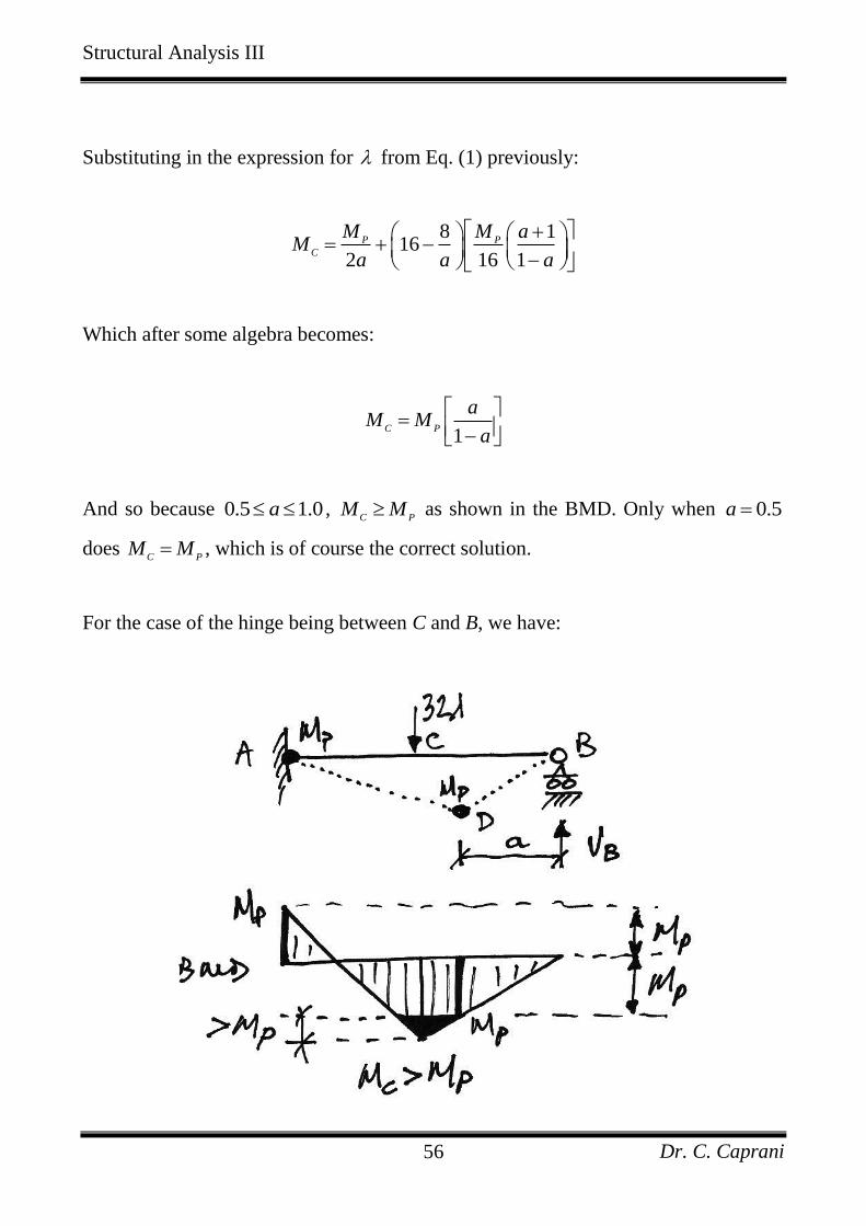
Substituting in the expression for from Eq. (1) previously:
8 1
162 16 1
P P
C
M M aM
a a a
Which after some algebra becomes:
1
C P
aM M
a
And so because 0.5 1.0a , C P
M M as shown in the BMD. Only when 0.5a
does C P
M M , which is of course the correct solution.
For the case of the hinge being between C and B, we have:
Structural Analysis III
Dr. C. Caprani 57
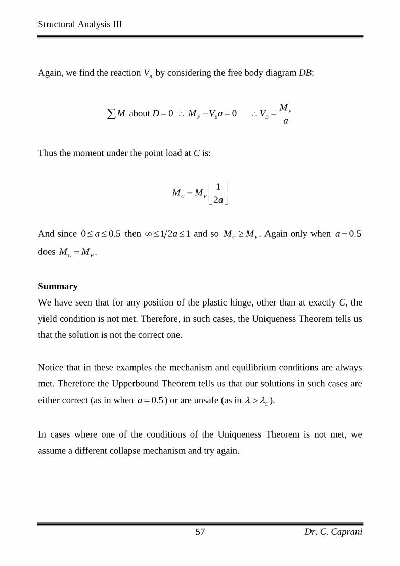
Again, we find the reaction B
V by considering the free body diagram DB:
about 0 0 P
P B B
MM D M V a V
a
Thus the moment under the point load at C is:
1
2C P
M Ma
And since 0 0.5a then 1 2 1a and so C P
M M . Again only when 0.5a
does C P
M M .
Summary
We have seen that for any position of the plastic hinge, other than at exactly C, the
yield condition is not met. Therefore, in such cases, the Uniqueness Theorem tells us
that the solution is not the correct one.
Notice that in these examples the mechanism and equilibrium conditions are always
met. Therefore the Upperbound Theorem tells us that our solutions in such cases are
either correct (as in when 0.5a ) or are unsafe (as in C
).
In cases where one of the conditions of the Uniqueness Theorem is not met, we
assume a different collapse mechanism and try again.
Structural Analysis III
Dr. C. Caprani 58
4.7 Plastic Design
Load Factor and Plastic Moment Capacity
When we come to design a structure using plastic methods, it is the load factor that is
known in advance and it is the plastic moment capacity that is the objective. The
general virtual work equations for a proposed collapse mechanism i is
,
e I
i j ji P ji ji
W W
P M
In which j is an individual load and deflection or plastic moment and rotation pair of
collapse mechanism i. If we take the P
M of each member to be some factor, , of a
nominal P
M , then we have:
i j ji P j ji
P M
Since work is a scalar quantity, and since the sum of work done on both sides is
positive, we can see that the load factor and plastic moment capacity have a linear
relationship of slope m for each collapse mechanism i:
j ji
i P
j ji
i i P
MP
m M
Thus for each collapse mechanism, 1m
k n , we can plot the load factor against the
plastic moment capacity. We do so for two cases:
Structural Analysis III
Dr. C. Caprani 59
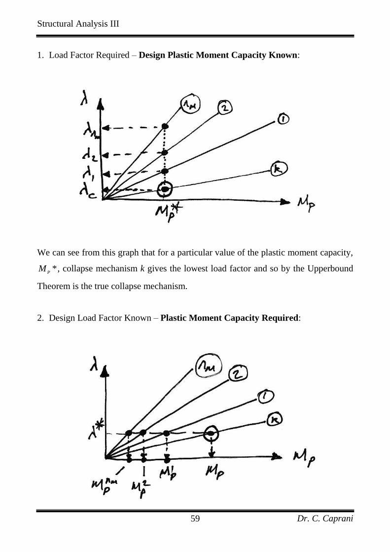
1. Load Factor Required – Design Plastic Moment Capacity Known:
We can see from this graph that for a particular value of the plastic moment capacity,
*P
M , collapse mechanism k gives the lowest load factor and so by the Upperbound
Theorem is the true collapse mechanism.
2. Design Load Factor Known – Plastic Moment Capacity Required:
Structural Analysis III
Dr. C. Caprani 60
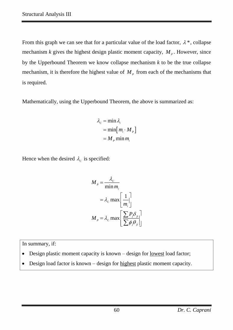
From this graph we can see that for a particular value of the load factor, * , collapse
mechanism k gives the highest design plastic moment capacity, P
M . However, since
by the Upperbound Theorem we know collapse mechanism k to be the true collapse
mechanism, it is therefore the highest value of P
M from each of the mechanisms that
is required.
Mathematically, using the Upperbound Theorem, the above is summarized as:
min
min
min
C i
i P
P i
m M
M m
Hence when the desired C is specified:
min
1max
max
C
P
i
C
i
j ji
P C
j jì
Mm
m
PM
In summary, if:
Design plastic moment capacity is known – design for lowest load factor;
Design load factor is known – design for highest plastic moment capacity.
Structural Analysis III
Dr. C. Caprani 61
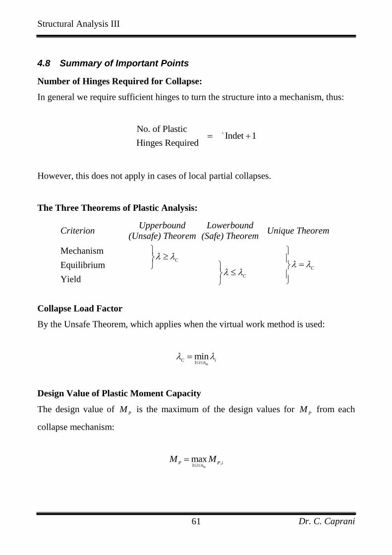
4.8 Summary of Important Points
Number of Hinges Required for Collapse:
In general we require sufficient hinges to turn the structure into a mechanism, thus:
No. of Plastic
Indet 1Hinges Required
However, this does not apply in cases of local partial collapses.
The Three Theorems of Plastic Analysis:
Criterion Upperbound
(Unsafe) Theorem
Lowerbound
(Safe) Theorem Unique Theorem
Mechanism C
C
Equilibrium C
Yield
Collapse Load Factor
By the Unsafe Theorem, which applies when the virtual work method is used:
m1
minC i
i n
Design Value of Plastic Moment Capacity
The design value of P
M is the maximum of the design values for P
M from each
collapse mechanism:
,
1max
mP P i
i nM M
Structural Analysis III
Dr. C. Caprani 62
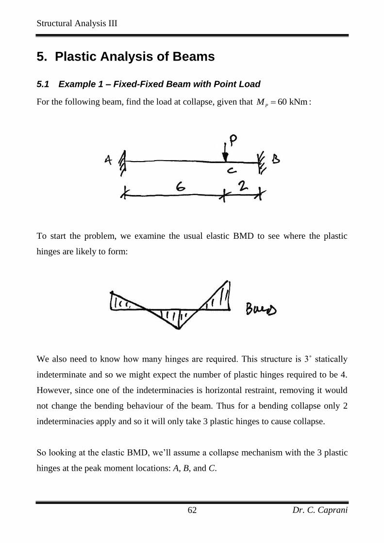
5. Plastic Analysis of Beams
5.1 Example 1 – Fixed-Fixed Beam with Point Load
For the following beam, find the load at collapse, given that 60 kNmP
M :
To start the problem, we examine the usual elastic BMD to see where the plastic
hinges are likely to form:
We also need to know how many hinges are required. This structure is 3˚ statically
indeterminate and so we might expect the number of plastic hinges required to be 4.
However, since one of the indeterminacies is horizontal restraint, removing it would
not change the bending behaviour of the beam. Thus for a bending collapse only 2
indeterminacies apply and so it will only take 3 plastic hinges to cause collapse.
So looking at the elastic BMD, we’ll assume a collapse mechanism with the 3 plastic
hinges at the peak moment locations: A, B, and C.
Structural Analysis III
Dr. C. Caprani 63
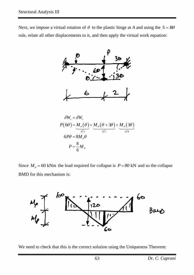
Next, we impose a virtual rotation of to the plastic hinge at A and using the S R
rule, relate all other displacements to it, and then apply the virtual work equation:
At At At
6 3 3
6 8
8
6
e I
P P P
A C B
P
P
W W
P M M M
P M
P M
Since 60 kNmP
M the load required for collapse is 80 kNP and so the collapse
BMD for this mechanism is:
We need to check that this is the correct solution using the Uniqueness Theorem:
Structural Analysis III
Dr. C. Caprani 64
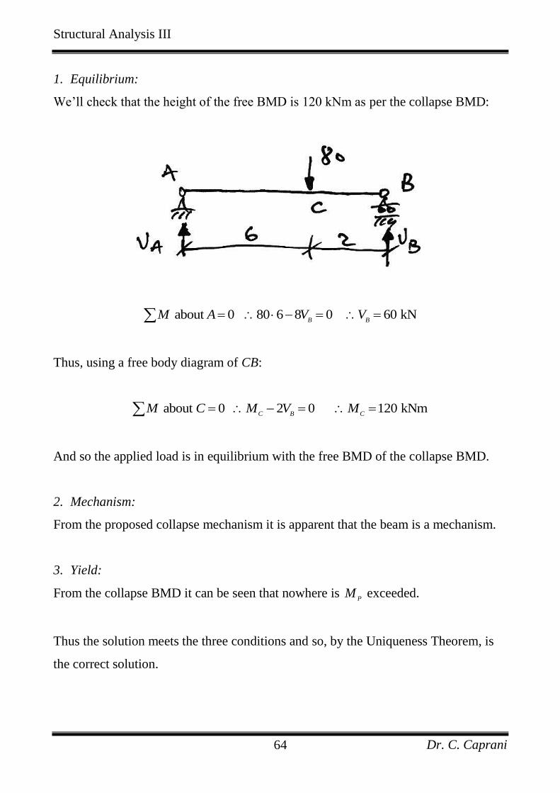
1. Equilibrium:
We’ll check that the height of the free BMD is 120 kNm as per the collapse BMD:
about 0 80 6 8 0 60 kNB B
M A V V
Thus, using a free body diagram of CB:
about 0 2 0 120 kNmC B C
M C M V M
And so the applied load is in equilibrium with the free BMD of the collapse BMD.
2. Mechanism:
From the proposed collapse mechanism it is apparent that the beam is a mechanism.
3. Yield:
From the collapse BMD it can be seen that nowhere is P
M exceeded.
Thus the solution meets the three conditions and so, by the Uniqueness Theorem, is
the correct solution.
Structural Analysis III
Dr. C. Caprani 65
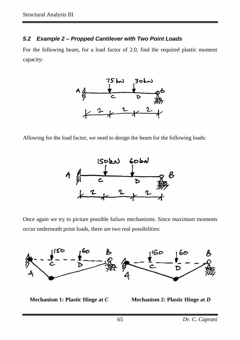
5.2 Example 2 – Propped Cantilever with Two Point Loads
For the following beam, for a load factor of 2.0, find the required plastic moment
capacity:
Allowing for the load factor, we need to design the beam for the following loads:
Once again we try to picture possible failure mechanisms. Since maximum moments
occur underneath point loads, there are two real possibilities:
Mechanism 1: Plastic Hinge at C Mechanism 2: Plastic Hinge at D
Structural Analysis III
Dr. C. Caprani 66
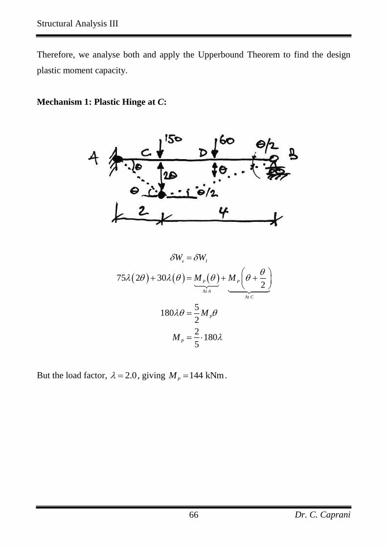
Therefore, we analyse both and apply the Upperbound Theorem to find the design
plastic moment capacity.
Mechanism 1: Plastic Hinge at C:
At
At
75 2 302
5180
2
2180
5
e I
P P
A
C
P
P
W W
M M
M
M
But the load factor, 2.0 , giving 144 kNmP
M .
Structural Analysis III
Dr. C. Caprani 67
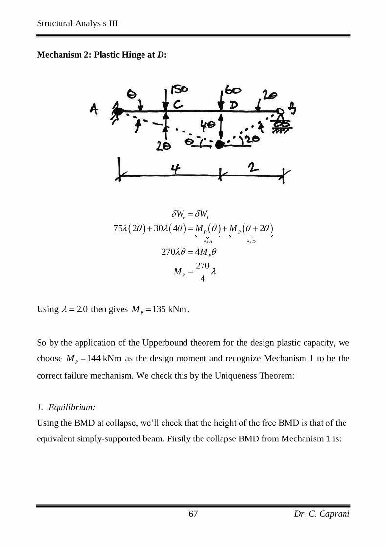
Mechanism 2: Plastic Hinge at D:
At At
75 2 30 4 2
270 4
270
4
e I
P P
A D
P
P
W W
M M
M
M
Using 2.0 then gives 135 kNmP
M .
So by the application of the Upperbound theorem for the design plastic capacity, we
choose 144 kNmP
M as the design moment and recognize Mechanism 1 to be the
correct failure mechanism. We check this by the Uniqueness Theorem:
1. Equilibrium:
Using the BMD at collapse, we’ll check that the height of the free BMD is that of the
equivalent simply-supported beam. Firstly the collapse BMD from Mechanism 1 is:
Structural Analysis III
Dr. C. Caprani 68
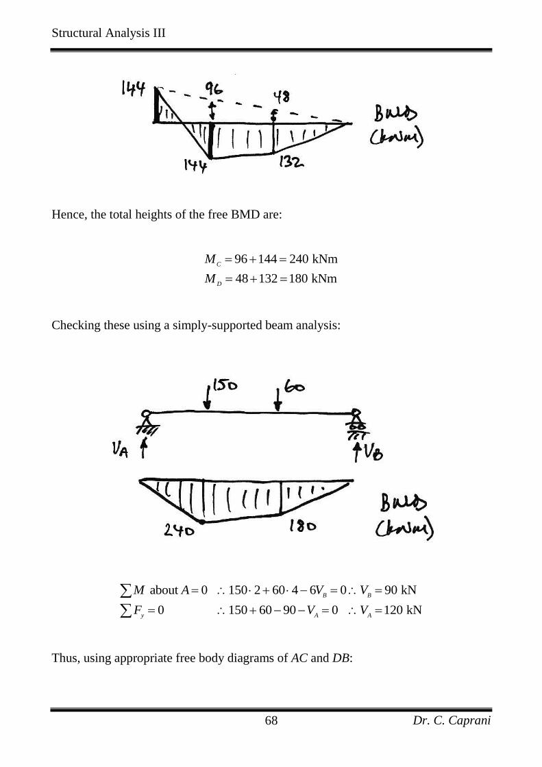
Hence, the total heights of the free BMD are:
96 144 240 kNm
48 132 180 kNm
C
D
M
M
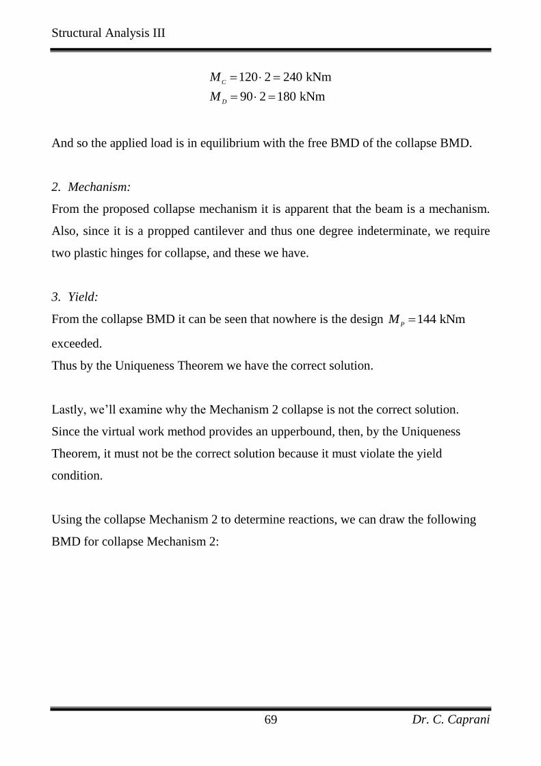
Checking these using a simply-supported beam analysis:
about 0 150 2 60 4 6 0 90 kN
0 150 60 90 0 120 kN
B B
y A A
M A V V
F V V
Thus, using appropriate free body diagrams of AC and DB:
Structural Analysis III
Dr. C. Caprani 69
120 2 240 kNm
90 2 180 kNm
C
D
M
M
And so the applied load is in equilibrium with the free BMD of the collapse BMD.
2. Mechanism:
From the proposed collapse mechanism it is apparent that the beam is a mechanism.
Also, since it is a propped cantilever and thus one degree indeterminate, we require
two plastic hinges for collapse, and these we have.
3. Yield:
From the collapse BMD it can be seen that nowhere is the design 144 kNmP
M
exceeded.
Thus by the Uniqueness Theorem we have the correct solution.
Lastly, we’ll examine why the Mechanism 2 collapse is not the correct solution.
Since the virtual work method provides an upperbound, then, by the Uniqueness
Theorem, it must not be the correct solution because it must violate the yield
condition.
Using the collapse Mechanism 2 to determine reactions, we can draw the following
BMD for collapse Mechanism 2:
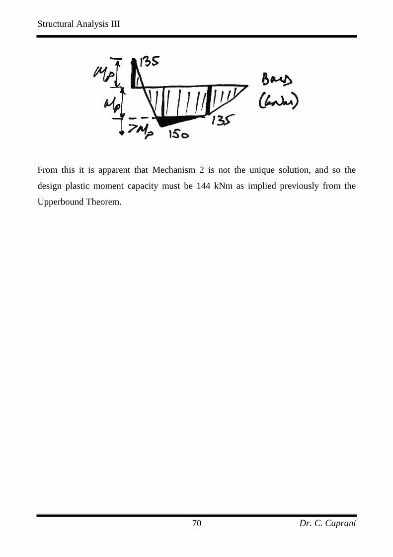
Structural Analysis III
Dr. C. Caprani 70
From this it is apparent that Mechanism 2 is not the unique solution, and so the
design plastic moment capacity must be 144 kNm as implied previously from the
Upperbound Theorem.
Structural Analysis III
Dr. C. Caprani 71
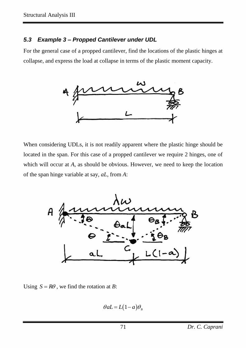
5.3 Example 3 – Propped Cantilever under UDL
For the general case of a propped cantilever, find the locations of the plastic hinges at
collapse, and express the load at collapse in terms of the plastic moment capacity.
When considering UDLs, it is not readily apparent where the plastic hinge should be
located in the span. For this case of a propped cantilever we require 2 hinges, one of
which will occur at A, as should be obvious. However, we need to keep the location
of the span hinge variable at say, aL, from A:
Using S R , we find the rotation at B:
1B
aL L a
Structural Analysis III
Dr. C. Caprani 72
And so:
1
B
a
a
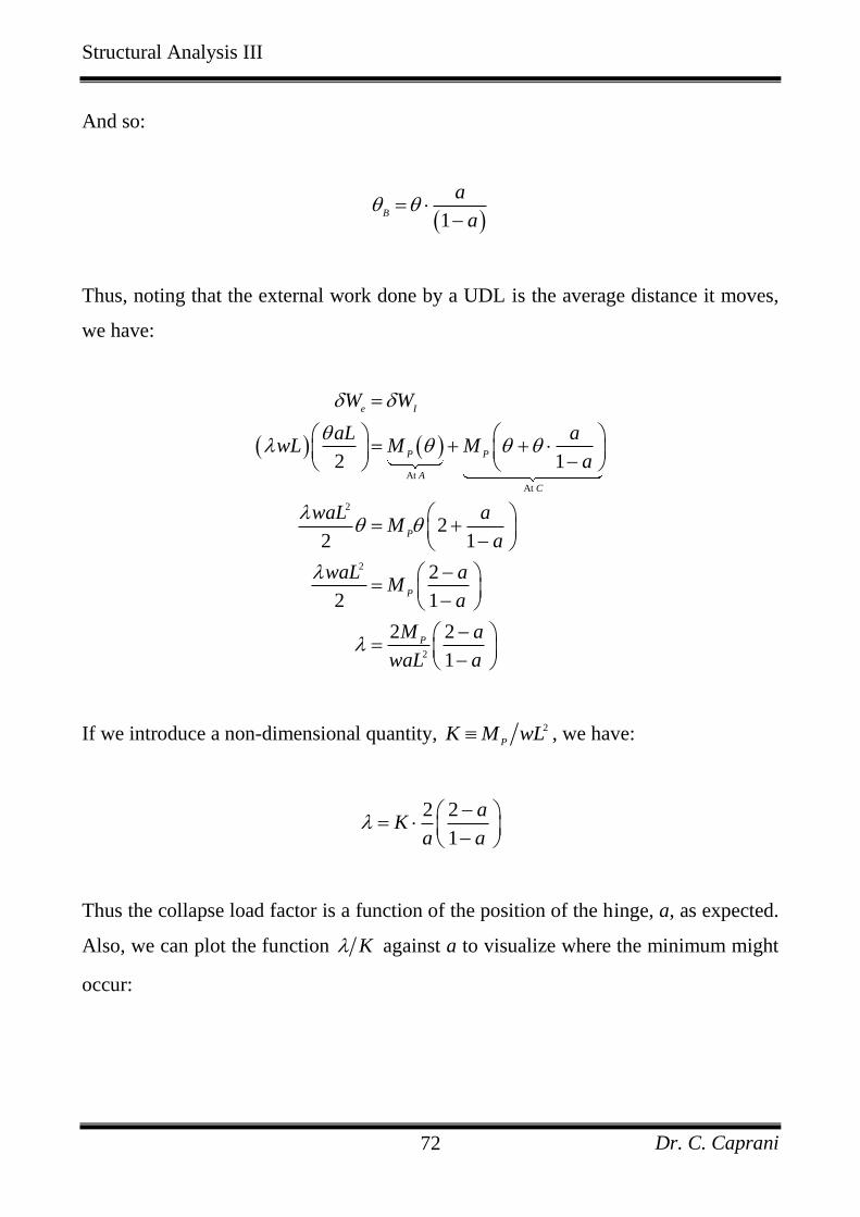
Thus, noting that the external work done by a UDL is the average distance it moves,
we have:
At
At
2
2
2
2 1
22 1
2
2 1
2 2
1
e I
P P
A
C
P
P
P
W W
aL awL M M
a
waL aM
a
waL aM
a
M a
waL a
If we introduce a non-dimensional quantity, 2
PK M wL , we have:
2 2
1
aK
a a
Thus the collapse load factor is a function of the position of the hinge, a, as expected.
Also, we can plot the function K against a to visualize where the minimum might
occur:
Structural Analysis III
Dr. C. Caprani 73
(0.586, 11.656)
0
2
4
6
8
10
12
14
16
18
20
0 0.2 0.4 0.6 0.8 1 1.2
Position Along Beam, aL
Non-d
imensio
nal C
olla
pse L
oad F
acto
r,
/K
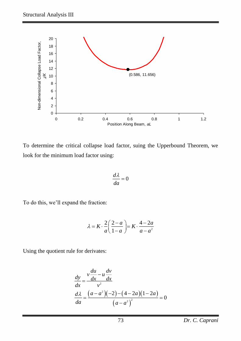
To determine the critical collapse load factor, suing the Upperbound Theorem, we
look for the minimum load factor using:
0d
da
To do this, we’ll expand the fraction:
2
2 2 4 2
1
a aK K
a a a a
Using the quotient rule for derivates:
2
2
22
2 4 2 1 20
du dvv u
dy dx dx
dx v
a a a ad
da a a
Structural Analysis III
Dr. C. Caprani 74
Thus multiplying across by 2
2a a and simplifying gives:
22 8 4 0a a
Thus:
28 8 4 2 4
2 2
2 2
a
Since we know 0 1a , then:
2 2 0.586a
At this value for a, the collapse load factor is:
2
2
2 2 0586
0.586 1 0.586
11.656
P
C
P
M
wL
M
wL
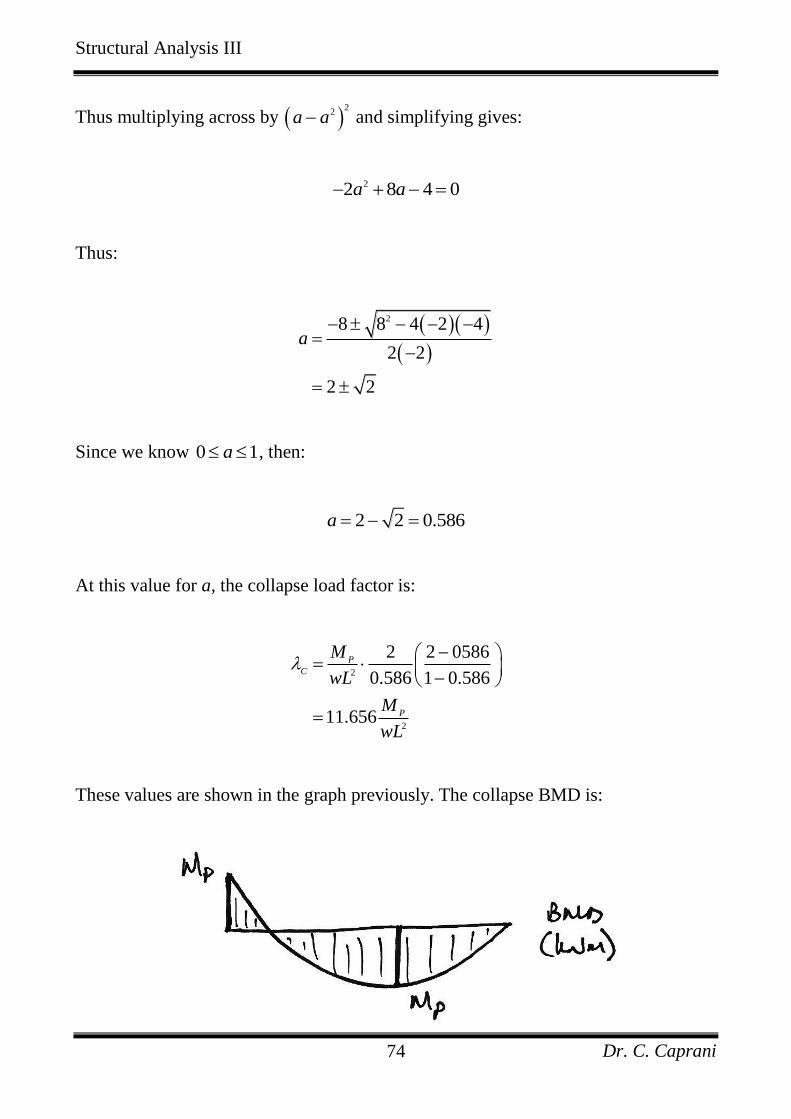
These values are shown in the graph previously. The collapse BMD is:
Structural Analysis III
Dr. C. Caprani 75
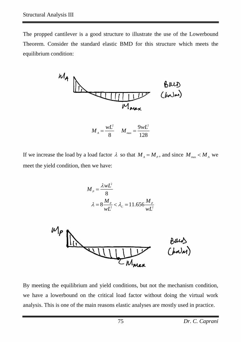
The propped cantilever is a good structure to illustrate the use of the Lowerbound
Theorem. Consider the standard elastic BMD for this structure which meets the
equilibrium condition:
2 29
8 128A max
wL wLM M
If we increase the load by a load factor so that A P
M M , and since max A
M M we
meet the yield condition, then we have:
2
2 2
8
8 11.656
P
P P
C
wLM
M M
wL wL
By meeting the equilibrium and yield conditions, but not the mechanism condition,
we have a lowerbound on the critical load factor without doing the virtual work
analysis. This is one of the main reasons elastic analyses are mostly used in practice.
Structural Analysis III
Dr. C. Caprani 76
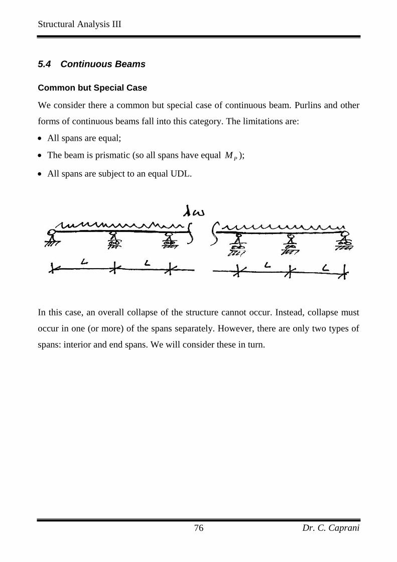
5.4 Continuous Beams
Common but Special Case
We consider there a common but special case of continuous beam. Purlins and other
forms of continuous beams fall into this category. The limitations are:
All spans are equal;
The beam is prismatic (so all spans have equal PM );
All spans are subject to an equal UDL.
In this case, an overall collapse of the structure cannot occur. Instead, collapse must
occur in one (or more) of the spans separately. However, there are only two types of
spans: interior and end spans. We will consider these in turn.
Structural Analysis III
Dr. C. Caprani 77
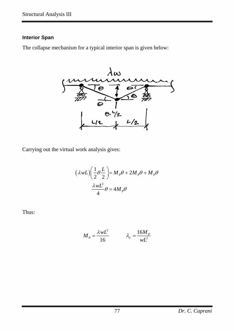
Interior Span
The collapse mechanism for a typical interior span is given below:
Carrying out the virtual work analysis gives:
2
12
2 2
44
P P P
P
LwL M M M
wLM
Thus:
2
2
16
16
PP C
wL MM
wL
Structural Analysis III
Dr. C. Caprani 78
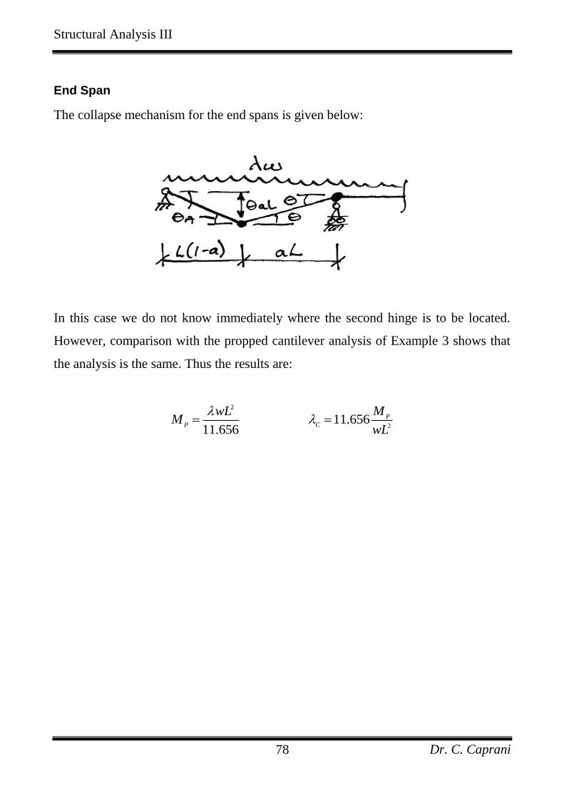
End Span
The collapse mechanism for the end spans is given below:
In this case we do not know immediately where the second hinge is to be located.
However, comparison with the propped cantilever analysis of Example 3 shows that
the analysis is the same. Thus the results are:
2
211.656
11.656
P
P C
wL MM
wL
Structural Analysis III
Dr. C. Caprani 79
Discussion
Immediately obvious from the forgoing analysis is that the end spans govern the
design of the beam: they require a plastic moment capacity 37% (16/11.656) greater
than the interior spans do.
Two possible solutions to this are apparent:
1. Strengthen the end spans: provide a section of 37% greater capacity for the end
span. Noting that the plastic hinge must form over the first interior support, the
connection (or splice) between the two beam sections should therefore occur at the
point of contraflexure in the penultimate span (about 0.2L inside the span).
2. Choose the span lengths so that a beam of prismatic section is optimized. The ratio
of lengths must be such that the plastic moments required are the same:
2 2
16 11.656
11.6560.853
16
Int End
P
End
Int
wL wLM
L
L
Thus the most economic design is one where the end spans are 85% of the interior
spans.
Lastly, since it is a single span that is considered to collapse at a time (and not the
overall structure), the number of hinges required is 1h r . Thus the collapse of a
continuous beam is always a partial or complete collapse.
Structural Analysis III
Dr. C. Caprani 80
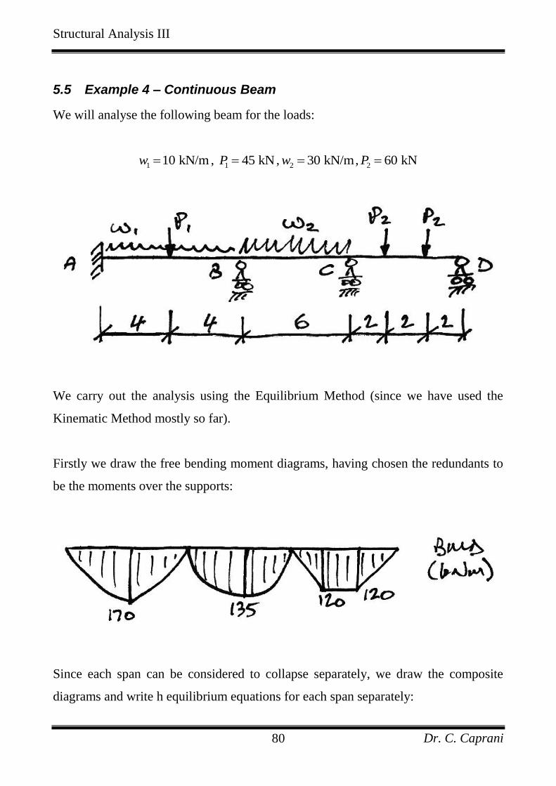
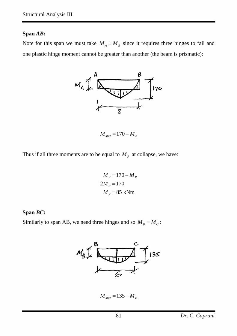
5.5 Example 4 – Continuous Beam
We will analyse the following beam for the loads:
1 10 kN/mw , 1 45 kNP ,
2 30 kN/mw ,2 60 kNP
We carry out the analysis using the Equilibrium Method (since we have used the
Kinematic Method mostly so far).
Firstly we draw the free bending moment diagrams, having chosen the redundants to
be the moments over the supports:
Since each span can be considered to collapse separately, we draw the composite
diagrams and write h equilibrium equations for each span separately:
Structural Analysis III
Dr. C. Caprani 81
Span AB:
Note for this span we must take A BM M since it requires three hinges to fail and
one plastic hinge moment cannot be greater than another (the beam is prismatic):
170Mid AM M
Thus if all three moments are to be equal to PM at collapse, we have:
170
2 170
85 kNm
P P
P
P
M M
M
M
Span BC:
Similarly to span AB, we need three hinges and so B CM M :
135Mid BM M
Structural Analysis III
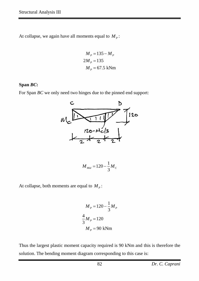
Dr. C. Caprani 82
At collapse, we again have all moments equal to PM :
135
2 135
67.5 kNm
P P
P
P
M M
M
M
Span BC:
For Span BC we only need two hinges due to the pinned end support:
1
1203
Mid CM M
At collapse, both moments are equal to PM :
1120
3
4120
3
90 kNm
P P
P
P
M M
M
M
Thus the largest plastic moment capacity required is 90 kNm and this is therefore the
solution. The bending moment diagram corresponding to this case is:
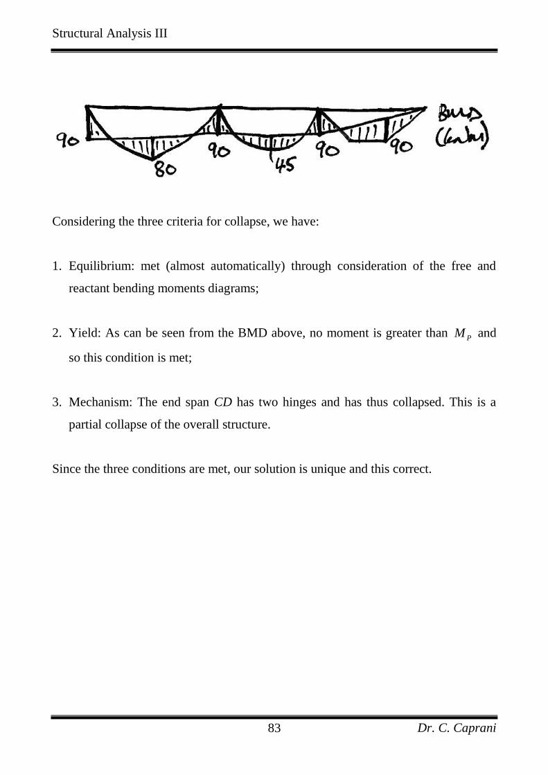
Structural Analysis III
Dr. C. Caprani 83
Considering the three criteria for collapse, we have:
1. Equilibrium: met (almost automatically) through consideration of the free and
reactant bending moments diagrams;
2. Yield: As can be seen from the BMD above, no moment is greater than PM and
so this condition is met;
3. Mechanism: The end span CD has two hinges and has thus collapsed. This is a
partial collapse of the overall structure.
Since the three conditions are met, our solution is unique and this correct.
Structural Analysis III
Dr. C. Caprani 84
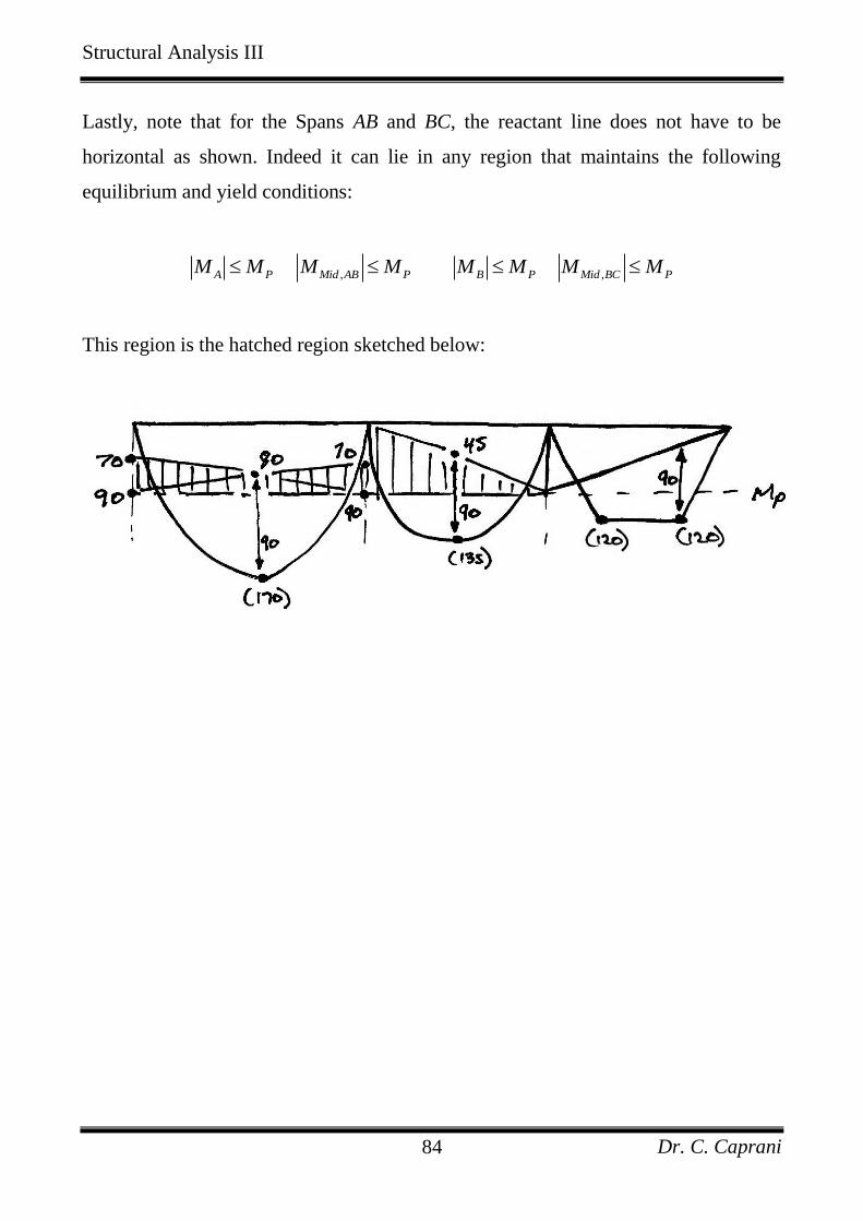
Lastly, note that for the Spans AB and BC, the reactant line does not have to be
horizontal as shown. Indeed it can lie in any region that maintains the following
equilibrium and yield conditions:
, ,A P Mid AB P B P Mid BC PM M M M M M M M
This region is the hatched region sketched below:
Structural Analysis III
Dr. C. Caprani 85
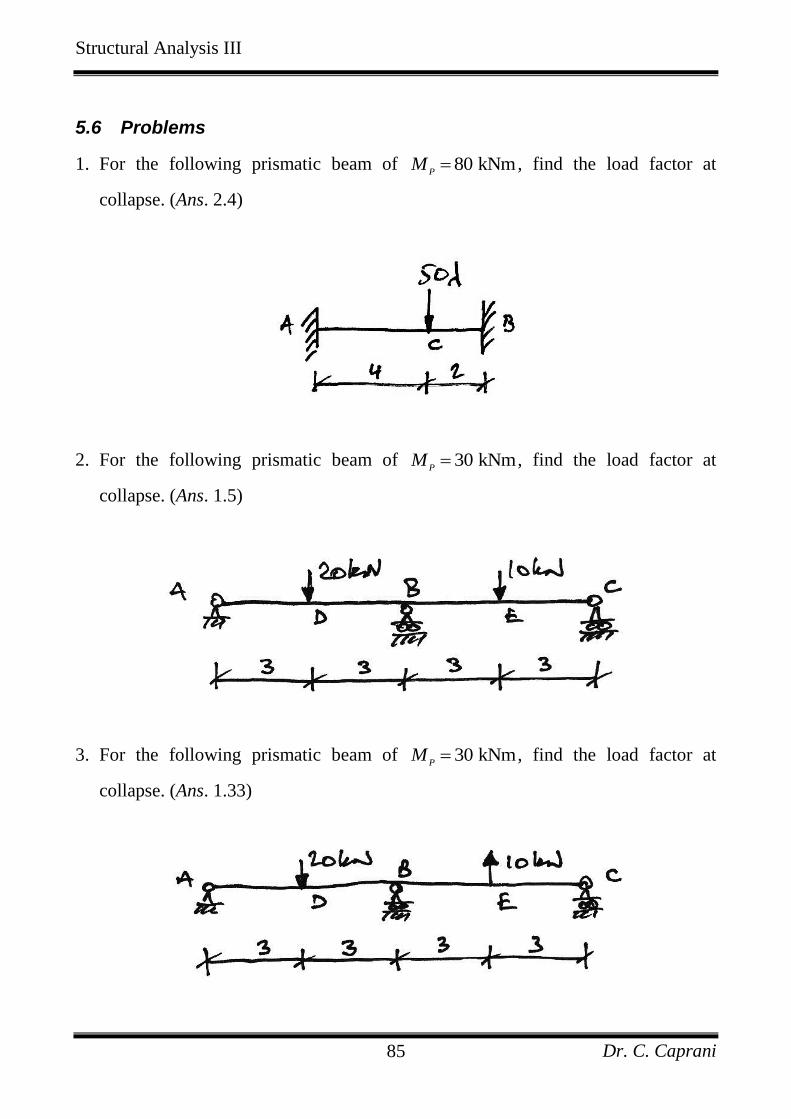
5.6 Problems
1. For the following prismatic beam of 80 kNmP
M , find the load factor at
collapse. (Ans. 2.4)
2. For the following prismatic beam of 30 kNmP
M , find the load factor at
collapse. (Ans. 1.5)
3. For the following prismatic beam of 30 kNmP
M , find the load factor at
collapse. (Ans. 1.33)
Structural Analysis III
Dr. C. Caprani 86
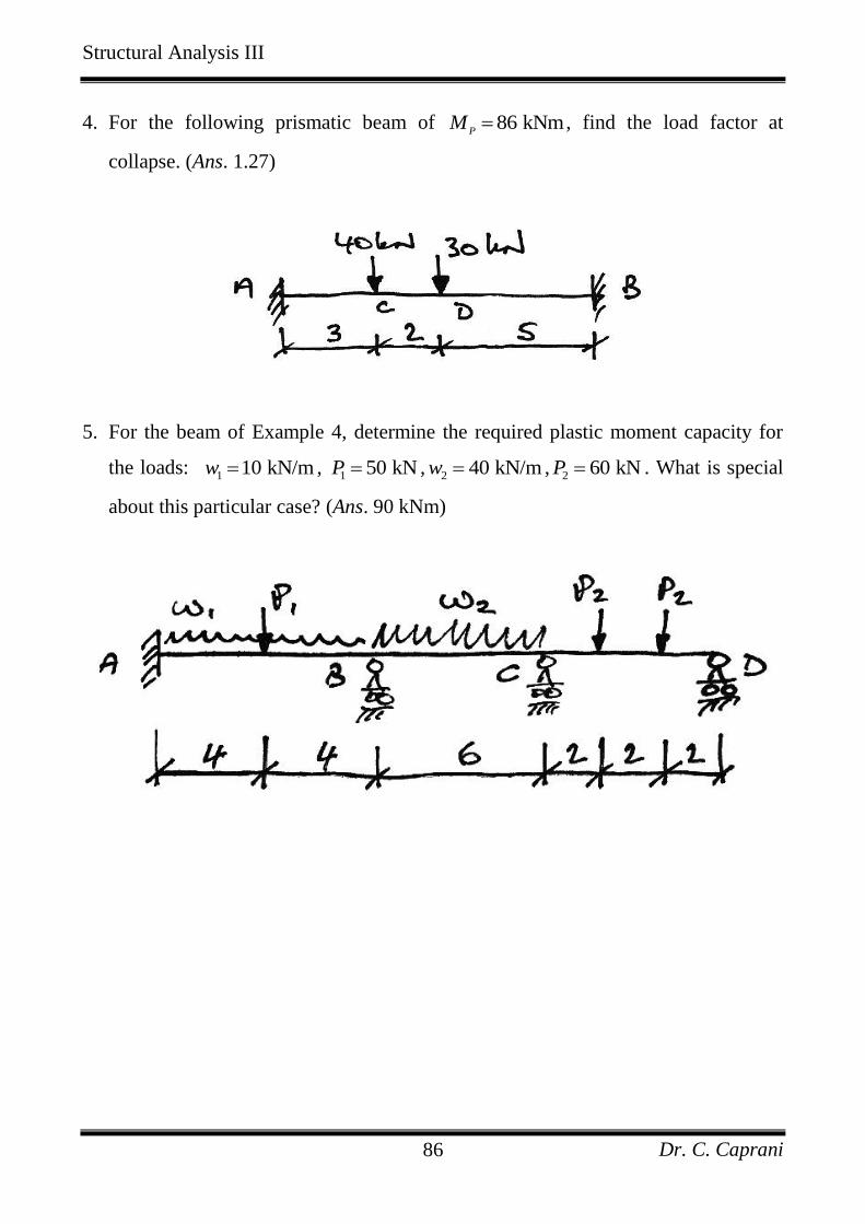
4. For the following prismatic beam of 86 kNmP
M , find the load factor at
collapse. (Ans. 1.27)
5. For the beam of Example 4, determine the required plastic moment capacity for
the loads: 1 10 kN/mw ,
1 50 kNP ,2 40 kN/mw ,
2 60 kNP . What is special
about this particular case? (Ans. 90 kNm)
Structural Analysis III
Dr. C. Caprani 87
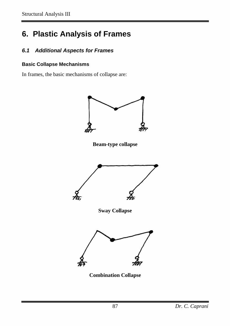
6. Plastic Analysis of Frames
6.1 Additional Aspects for Frames
Basic Collapse Mechanisms
In frames, the basic mechanisms of collapse are:
Beam-type collapse
Sway Collapse
Combination Collapse
Structural Analysis III
Dr. C. Caprani 88
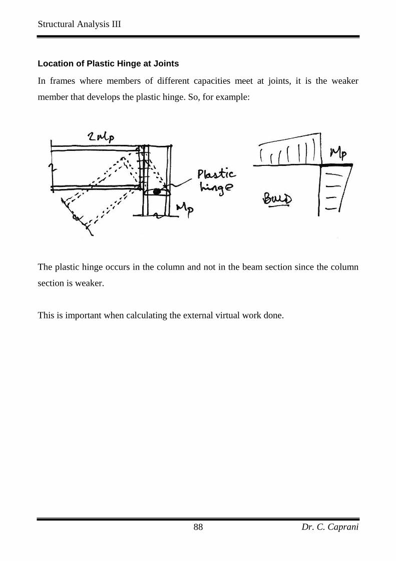
Location of Plastic Hinge at Joints
In frames where members of different capacities meet at joints, it is the weaker
member that develops the plastic hinge. So, for example:
The plastic hinge occurs in the column and not in the beam section since the column
section is weaker.
This is important when calculating the external virtual work done.
Structural Analysis III
Dr. C. Caprani 89
Combination of Mechanisms
One of the most powerful tools in plastic analysis is Combination of Mechanisms.
This allows us to work out the virtual work equations for the beam and sway
collapses separately and then combine them to find the collapse load factor for a
combination collapse mechanism.
Combination of mechanisms is based on the idea that there are only a certain number
of independent equilibrium equations for a structure. Any further equations are
obtained from a combination of these independent equations. Since equilibrium
equations can be obtained using virtual work applied to a possible collapse
mechanism, it follows that there are independent collapse mechanisms, and other
collapse mechanisms that may be obtained form a combination of the independent
collapse mechanisms.
As we saw for the propped cantilever case of one redundant (r = 1), we required two
hinges, h = 2 for collapse, and wrote one independent equilibrium equation
4C AM PL M . Generally, there are h r independent equilibrium equations, and
thus h r independent collapse mechanisms.
It must be noted here that in combining collapse mechanisms it is essential that
hinges rotating in opposing senses must be cancelled to avoid having two degrees of
freedom.
The method is better explained by the examples that follow.
Structural Analysis III
Dr. C. Caprani 90
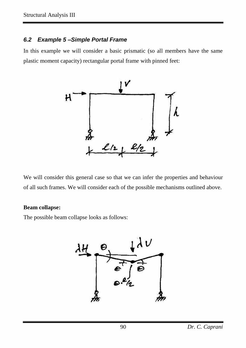
6.2 Example 5 –Simple Portal Frame
In this example we will consider a basic prismatic (so all members have the same
plastic moment capacity) rectangular portal frame with pinned feet:
We will consider this general case so that we can infer the properties and behaviour
of all such frames. We will consider each of the possible mechanisms outlined above.
Beam collapse:
The possible beam collapse looks as follows:
Structural Analysis III
Dr. C. Caprani 91
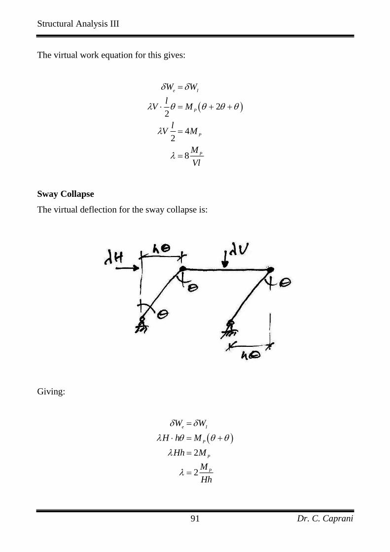
The virtual work equation for this gives:
22
42
8
e I
P
P
P
W W
lV M
lV M
M
Vl
Sway Collapse
The virtual deflection for the sway collapse is:
Giving:
2
2
e I
P
P
P
W W
H h M
Hh M
M
Hh
Structural Analysis III
Dr. C. Caprani 92
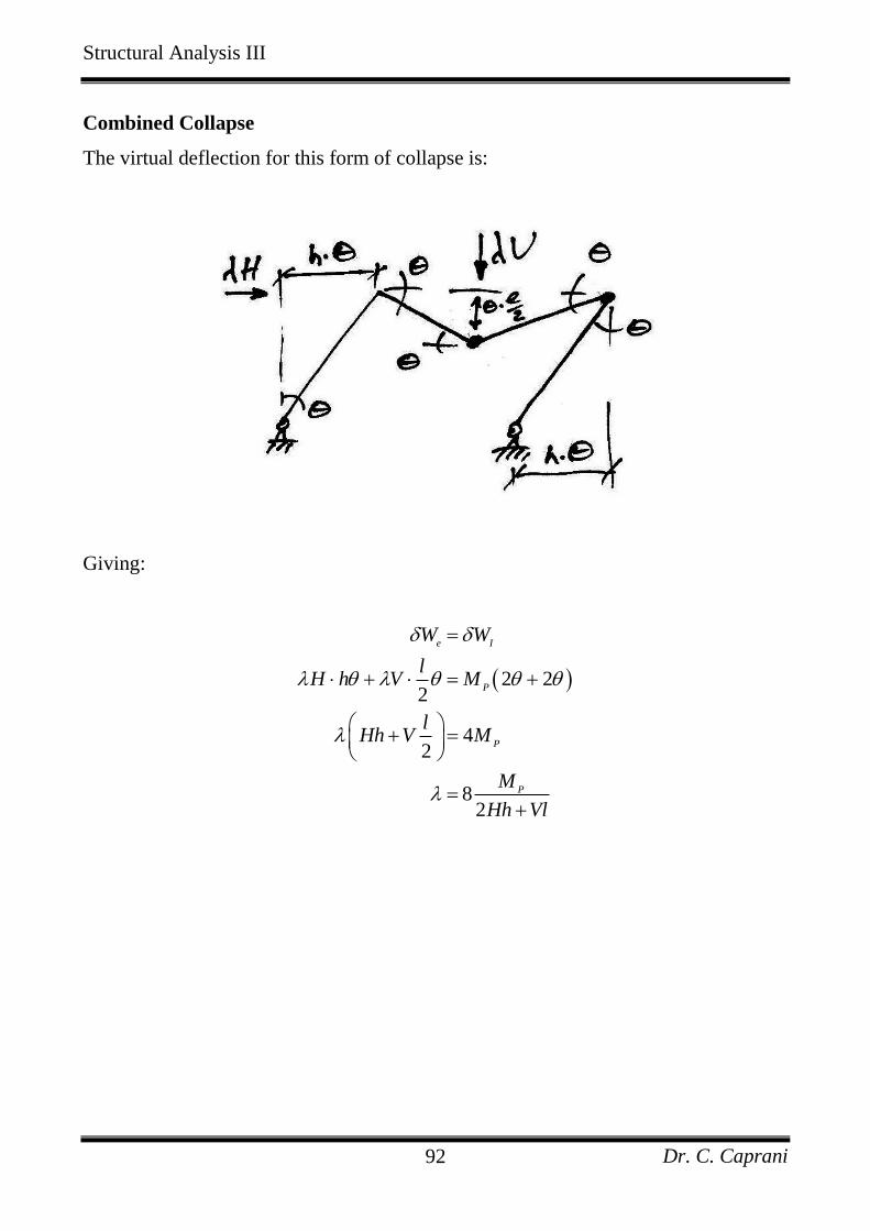
Combined Collapse
The virtual deflection for this form of collapse is:
Giving:
2 22
42
82
e I
P
P
P
W W
lH h V M
lHh V M
M
Hh Vl
Structural Analysis III
Dr. C. Caprani 93
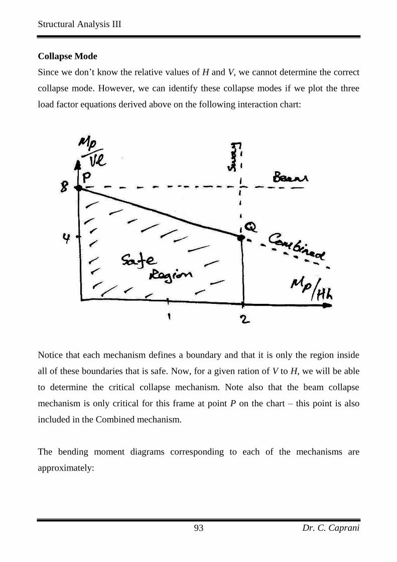
Collapse Mode
Since we don’t know the relative values of H and V, we cannot determine the correct
collapse mode. However, we can identify these collapse modes if we plot the three
load factor equations derived above on the following interaction chart:
Notice that each mechanism defines a boundary and that it is only the region inside
all of these boundaries that is safe. Now, for a given ration of V to H, we will be able
to determine the critical collapse mechanism. Note also that the beam collapse
mechanism is only critical for this frame at point P on the chart – this point is also
included in the Combined mechanism.
The bending moment diagrams corresponding to each of the mechanisms are
approximately:
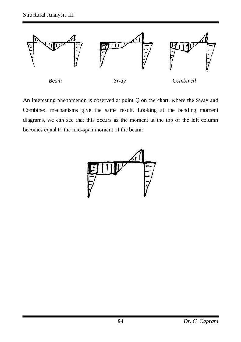
Structural Analysis III
Dr. C. Caprani 94
Beam Sway Combined
An interesting phenomenon is observed at point Q on the chart, where the Sway and
Combined mechanisms give the same result. Looking at the bending moment
diagrams, we can see that this occurs as the moment at the top of the left column
becomes equal to the mid-span moment of the beam:
Structural Analysis III
Dr. C. Caprani 95
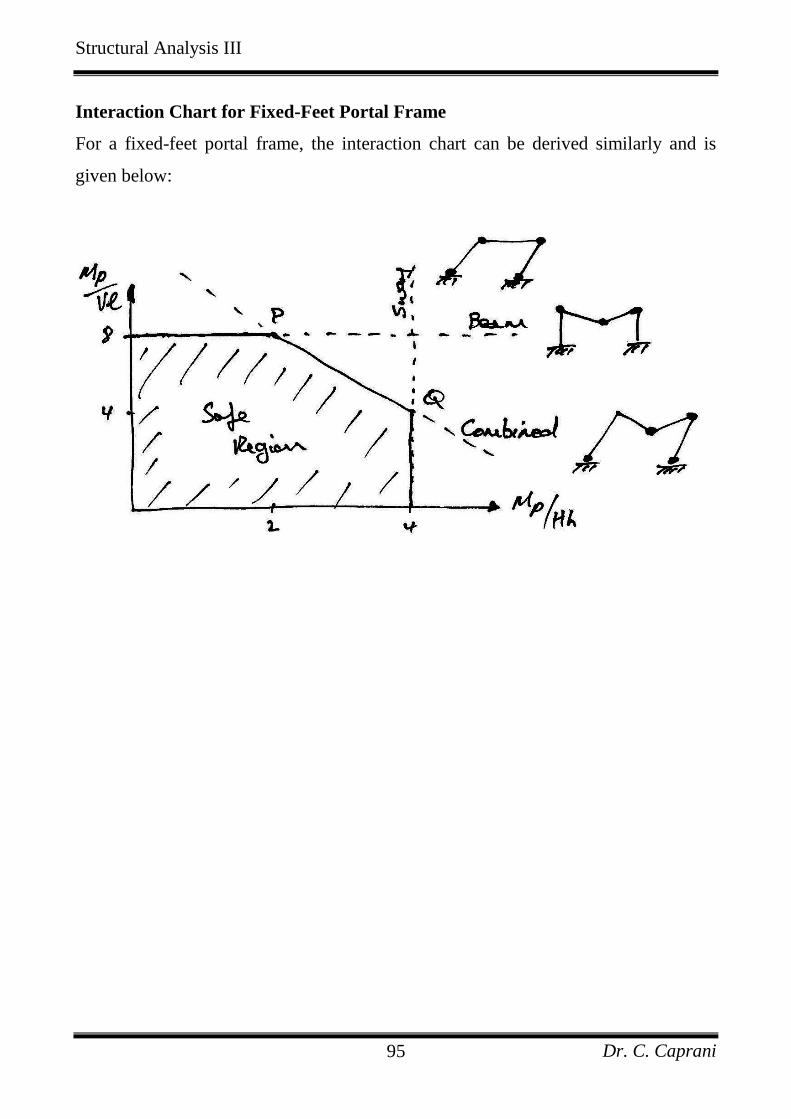
Interaction Chart for Fixed-Feet Portal Frame
For a fixed-feet portal frame, the interaction chart can be derived similarly and is
given below:
Structural Analysis III
Dr. C. Caprani 96
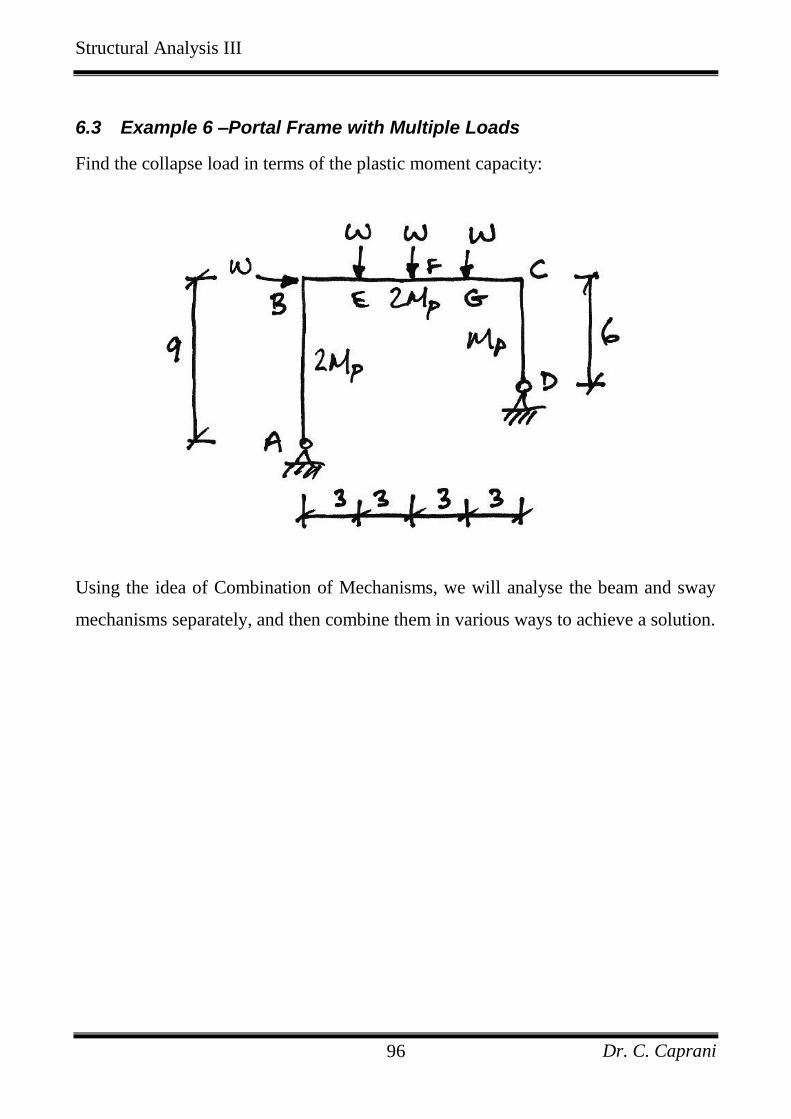
6.3 Example 6 –Portal Frame with Multiple Loads
Find the collapse load in terms of the plastic moment capacity:
Using the idea of Combination of Mechanisms, we will analyse the beam and sway
mechanisms separately, and then combine them in various ways to achieve a solution.
Structural Analysis III
Dr. C. Caprani 97
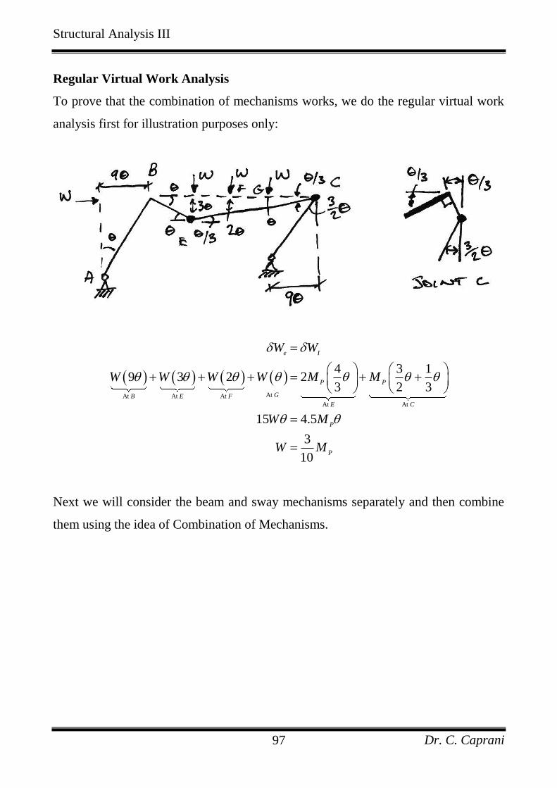
Regular Virtual Work Analysis
To prove that the combination of mechanisms works, we do the regular virtual work
analysis first for illustration purposes only:
At At At At
At At
4 3 19 3 2 2
3 2 3
15 4.5
3
10
e I
P P
GB E F
E C
P
P
W W
W W W W M M
W M
W M
Next we will consider the beam and sway mechanisms separately and then combine
them using the idea of Combination of Mechanisms.
Structural Analysis III
Dr. C. Caprani 98
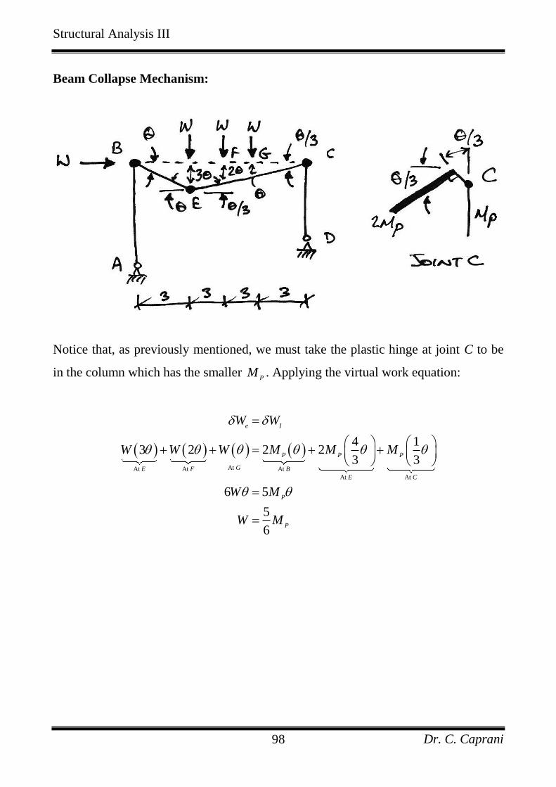
Beam Collapse Mechanism:
Notice that, as previously mentioned, we must take the plastic hinge at joint C to be
in the column which has the smaller P
M . Applying the virtual work equation:
At At At At
At At
4 13 2 2 2
3 3
6 5
5
6
e I
P P P
GE F B
E C
P
P
W W
W W W M M M
W M
W M

Structural Analysis III
Dr. C. Caprani 99
Sway Collapse Mechanism:
Again notice how careful we are of the hinge location at joint C.
At At
At
39 2
2
9 3.5
7
18
e I
P P
B B
C
P
P
W W
W M M
W M
W M
Structural Analysis III
Dr. C. Caprani 100
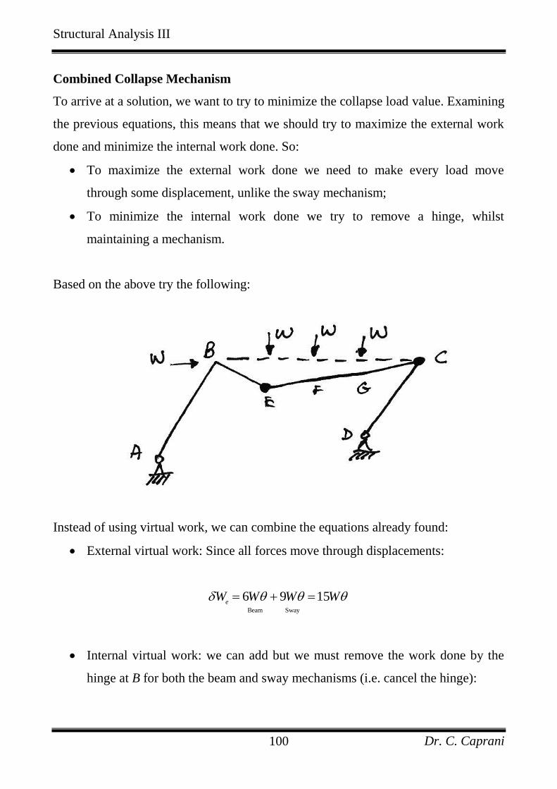
Combined Collapse Mechanism
To arrive at a solution, we want to try to minimize the collapse load value. Examining
the previous equations, this means that we should try to maximize the external work
done and minimize the internal work done. So:
To maximize the external work done we need to make every load move
through some displacement, unlike the sway mechanism;
To minimize the internal work done we try to remove a hinge, whilst
maintaining a mechanism.
Based on the above try the following:
Instead of using virtual work, we can combine the equations already found:
External virtual work: Since all forces move through displacements:
Beam Sway
6 9 15e
W W W W
Internal virtual work: we can add but we must remove the work done by the
hinge at B for both the beam and sway mechanisms (i.e. cancel the hinge):
Structural Analysis III
Dr. C. Caprani 101
Beam Hinge - Beam Hinge - SwaySway
5 3.5 2 2 4.5I P P P P P
B B
W M M M M M
Thus we have:
15 4.5
3
10
e I
P
P
W W
W M
W M
Since this is lower than either of the previous mechanisms (beam or sway), we think
this is the solution, and so check against the three conditions of the Uniqueness
Theorem.
At this point we note that the result above is the same as that found by the usual
Virtual Work analysis, thus verifying the concept of Combination of Mechanisms.
Of course, regardless of the means of arriving at a possible collapse load, we must
verify the uniqueness of the load factor using the three conditions, noting that
3.33P
M W .
Structural Analysis III
Dr. C. Caprani 102
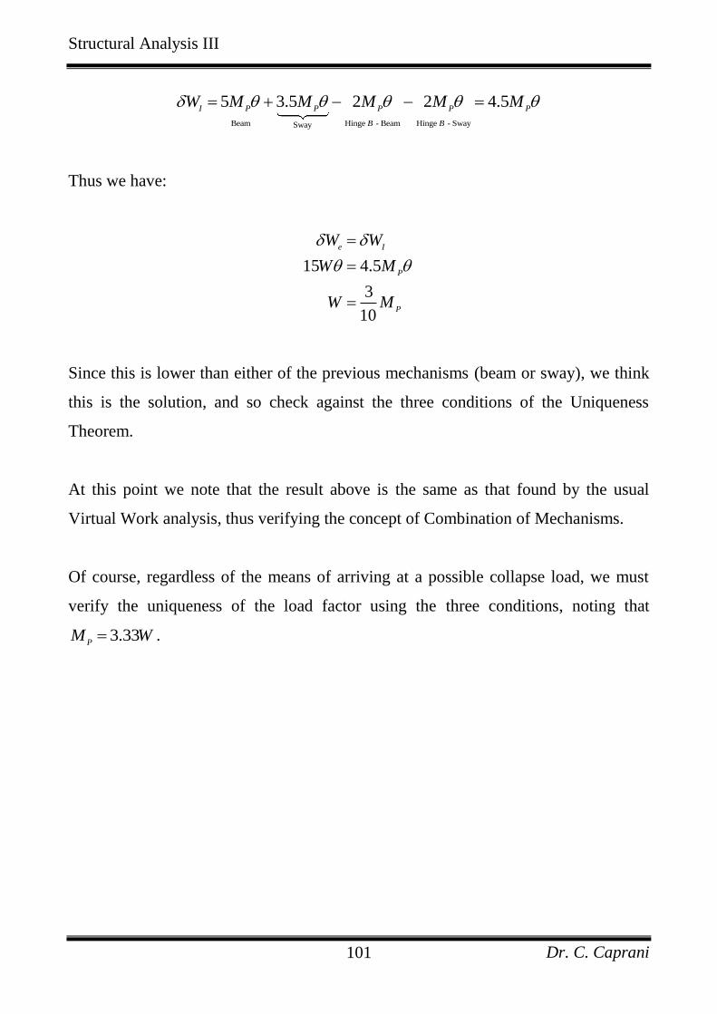
Uniqueness Theorem Checks
1. Equilibrium:
We start by determining the reactions:
about 0 6 0
3.330.55
6 6
D P
P
D
M C H M
M WH W
0 0.55 0.45x A
F H W W W
For the whole frame:
about 0 12 3 6 9 6 3 0 0.89A A A
M D V H W W W W V W
Thus the moment at E, from a free-body diagram of ABE, is:
about 0 3 9 0 6.71A A E E
M E V H M M W
Since there is a plastic hinge at E of value 2 2 3.33 6.67P
M W W we have
equilibrium.
2. Mechanism:
The frame is obviously a mechanism since 3 4 2 3 1R C .
3. Yield:
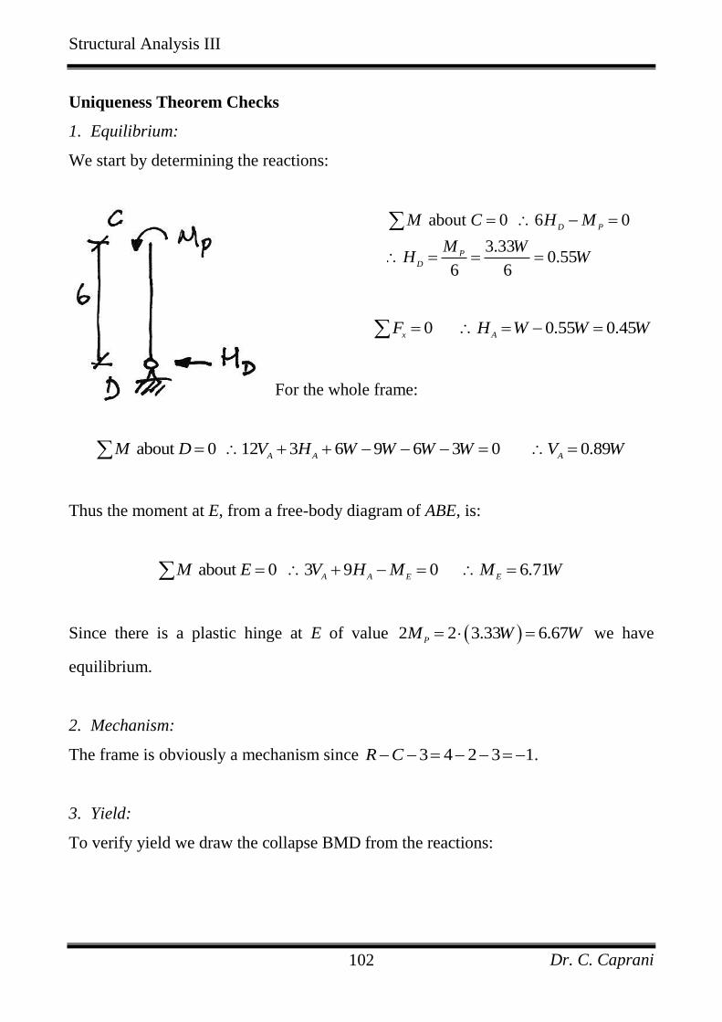
To verify yield we draw the collapse BMD from the reactions:
Structural Analysis III
Dr. C. Caprani 103
From the diagram we see that there are no moments greater than 2 6.67P
M W in
members AB and BC, and no moments greater than 3.33P
M W in member CD.
Structural Analysis III
Dr. C. Caprani 104
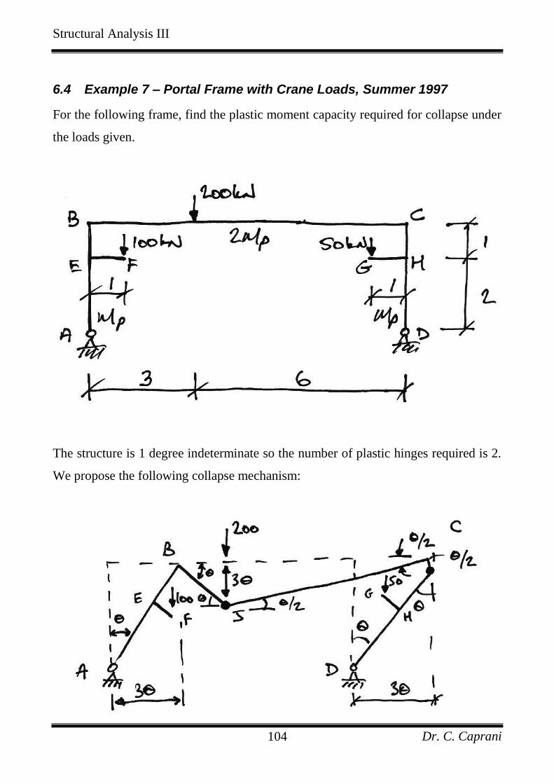
6.4 Example 7 – Portal Frame with Crane Loads, Summer 1997
For the following frame, find the plastic moment capacity required for collapse under
the loads given.
The structure is 1 degree indeterminate so the number of plastic hinges required is 2.
We propose the following collapse mechanism:
Structural Analysis III
Dr. C. Caprani 105
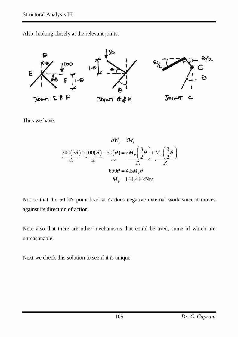
Also, looking closely at the relevant joints:
Thus we have:
At At At
At At
3 3200 3 100 50 2
2 2
650 4.5
144.44 kNm
e I
P P
GJ F
J C
P
P
W W
M M
M
M
Notice that the 50 kN point load at G does negative external work since it moves
against its direction of action.
Note also that there are other mechanisms that could be tried, some of which are
unreasonable.
Next we check this solution to see if it is unique:
Structural Analysis III
Dr. C. Caprani 106
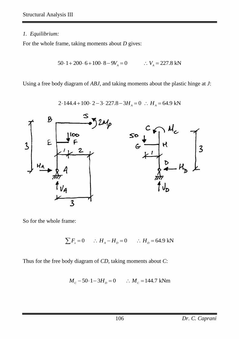
1. Equilibrium:
For the whole frame, taking moments about D gives:
50 1 200 6 100 8 9 0 227.8 kNA A
V V
Using a free body diagram of ABJ, and taking moments about the plastic hinge at J:
2 144.4 100 2 3 227.8 3 0 64.9 kNA A
H H
So for the whole frame:
0 0 64.9 kNx A D D
F H H H
Thus for the free body diagram of CD, taking moments about C:
50 1 3 0 144.7 kNmC D C
M H M
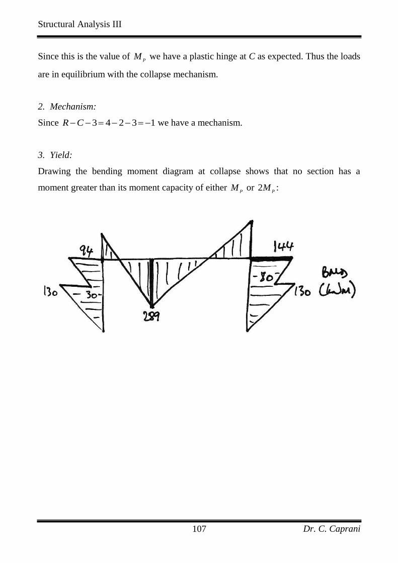
Structural Analysis III
Dr. C. Caprani 107
Since this is the value of P
M we have a plastic hinge at C as expected. Thus the loads
are in equilibrium with the collapse mechanism.
2. Mechanism:
Since 3 4 2 3 1R C we have a mechanism.
3. Yield:
Drawing the bending moment diagram at collapse shows that no section has a
moment greater than its moment capacity of either P
M or 2P
M :

Structural Analysis III
Dr. C. Caprani 108
6.5 Example 8 – Oblique Frame, Sumer 1999
Problem
The following rigid-jointed frame is loaded with working loads as shown:
1. Find the value of the collapse load factor when 120 kNmP
M ;
2. Show that your solution is the unique solution;
3. Sketch the bending moment diagram at collapse, showing all important values.
Solution
To solve this problem, first we will consider the basic mechanisms of collapse.
Examining these, we will then use Combination of Mechanisms to find a mechanism
(or more) that attempts to maximize external work and minimize internal work. We
will then verify our solution using the Uniqueness Theorem.
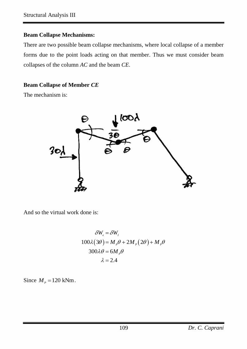
Structural Analysis III
Dr. C. Caprani 109
Beam Collapse Mechanisms:
There are two possible beam collapse mechanisms, where local collapse of a member
forms due to the point loads acting on that member. Thus we must consider beam
collapses of the column AC and the beam CE.
Beam Collapse of Member CE
The mechanism is:
And so the virtual work done is:
100 3 2 2
300 6
2.4
e I
P P P
P
W W
M M M
M
Since 120 kNmP
M .
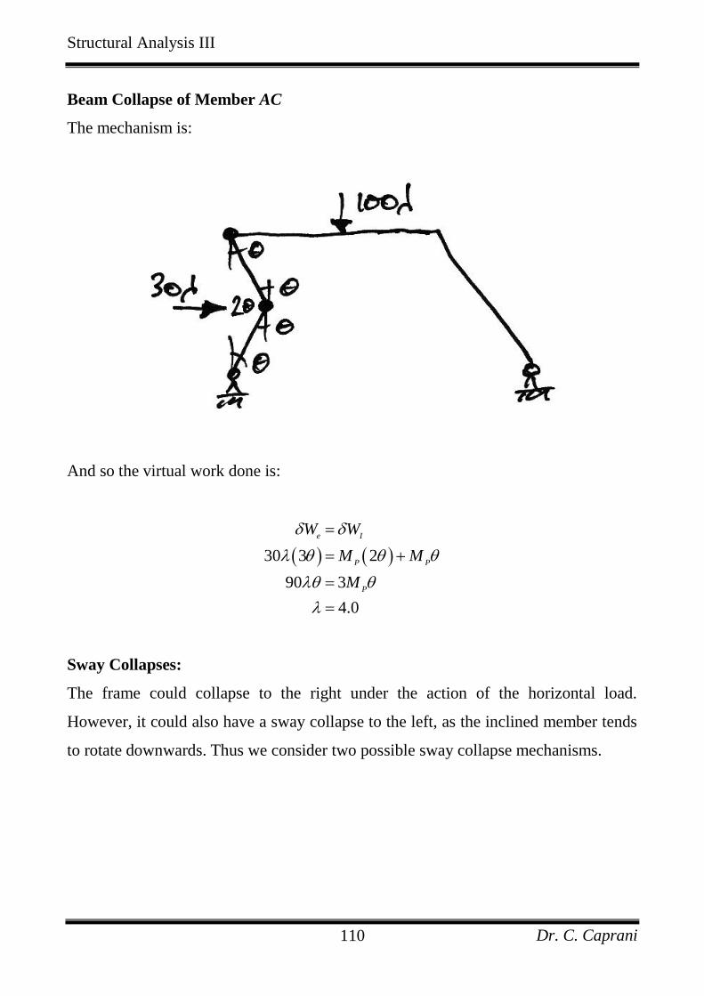
Structural Analysis III
Dr. C. Caprani 110
Beam Collapse of Member AC
The mechanism is:
And so the virtual work done is:
30 3 2
90 3
4.0
e I
P P
P
W W
M M
M
Sway Collapses:
The frame could collapse to the right under the action of the horizontal load.
However, it could also have a sway collapse to the left, as the inclined member tends
to rotate downwards. Thus we consider two possible sway collapse mechanisms.
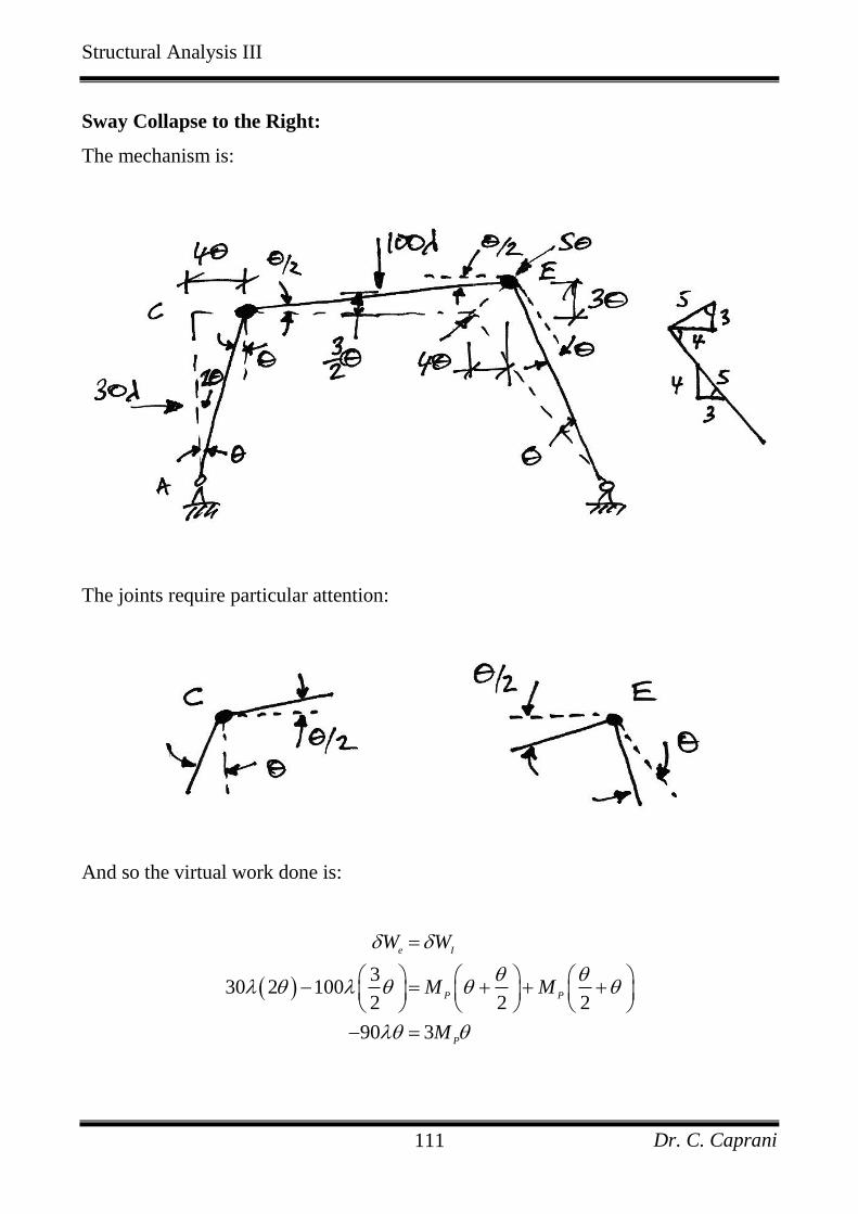
Structural Analysis III
Dr. C. Caprani 111
Sway Collapse to the Right:
The mechanism is:
The joints require particular attention:
And so the virtual work done is:
3
30 2 1002 2 2
90 3
e I
P P
P
W W
M M
M
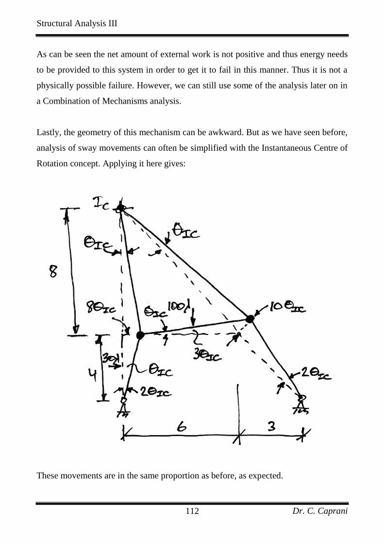
Structural Analysis III
Dr. C. Caprani 112
As can be seen the net amount of external work is not positive and thus energy needs
to be provided to this system in order to get it to fail in this manner. Thus it is not a
physically possible failure. However, we can still use some of the analysis later on in
a Combination of Mechanisms analysis.
Lastly, the geometry of this mechanism can be awkward. But as we have seen before,
analysis of sway movements can often be simplified with the Instantaneous Centre of
Rotation concept. Applying it here gives:
These movements are in the same proportion as before, as expected.
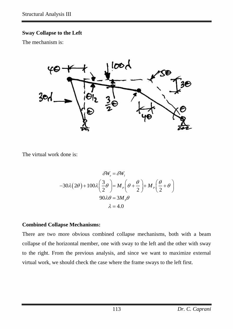
Structural Analysis III
Dr. C. Caprani 113
Sway Collapse to the Left
The mechanism is:
The virtual work done is:
330 2 100
2 2 2
90 3
4.0
e I
P P
P
W W
M M
M
Combined Collapse Mechanisms:
There are two more obvious combined collapse mechanisms, both with a beam
collapse of the horizontal member, one with sway to the left and the other with sway
to the right. From the previous analysis, and since we want to maximize external
virtual work, we should check the case where the frame sways to the left first.
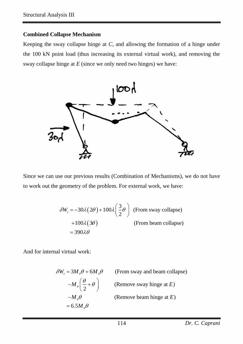
Structural Analysis III
Dr. C. Caprani 114
Combined Collapse Mechanism
Keeping the sway collapse hinge at C, and allowing the formation of a hinge under
the 100 kN point load (thus increasing its external virtual work), and removing the
sway collapse hinge at E (since we only need two hinges) we have:
Since we can use our previous results (Combination of Mechanisms), we do not have
to work out the geometry of the problem. For external work, we have:
330 2 100 (From sway collapse)
2
100 3 (From beam collapse)
390
eW
And for internal virtual work:
3 6 (From sway and beam collapse)
(Remove sway hinge at )2
(Remove beam hinge at )
6.5
I P P
P
P
P
W M M
M E
M E
M
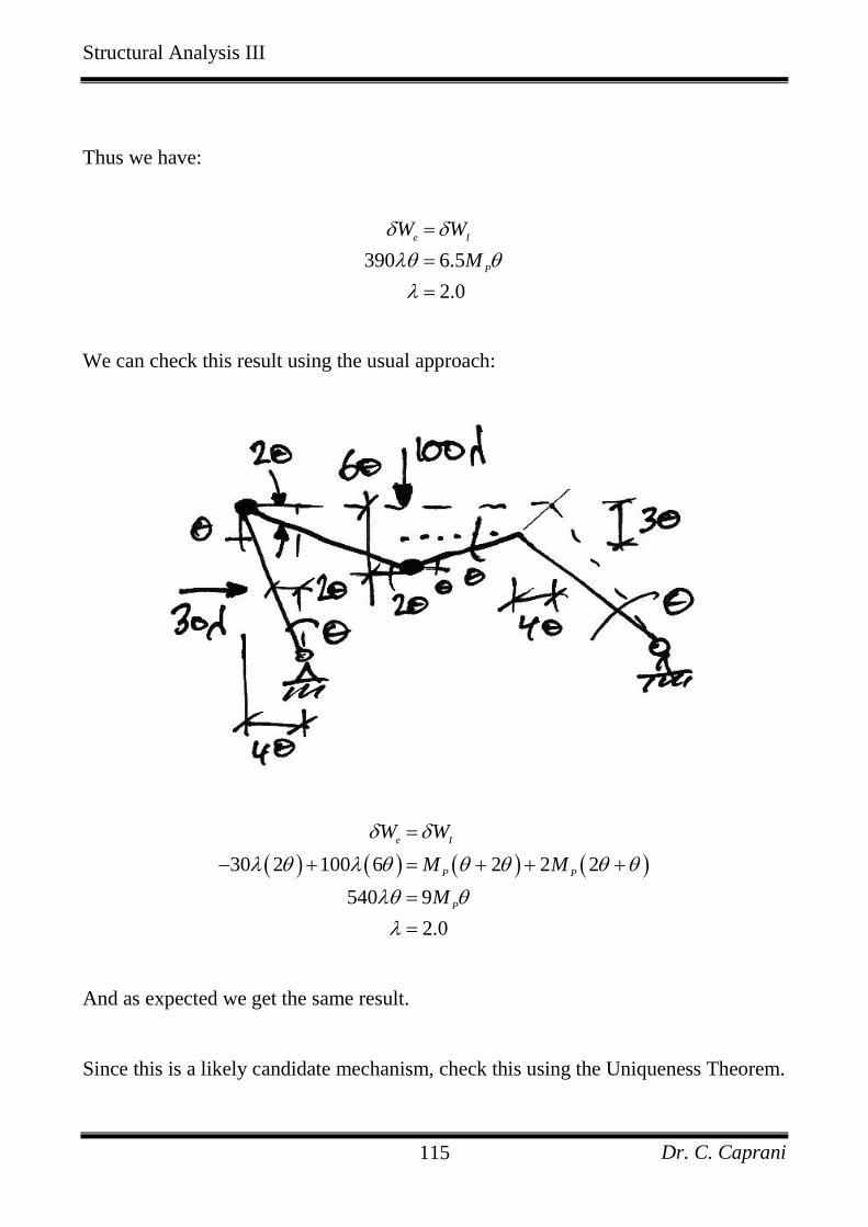
Structural Analysis III
Dr. C. Caprani 115
Thus we have:
390 6.5
2.0
e I
P
W W
M
We can check this result using the usual approach:
30 2 100 6 2 2 2
540 9
2.0
e I
P P
P
W W
M M
M
And as expected we get the same result.
Since this is a likely candidate mechanism, check this using the Uniqueness Theorem.
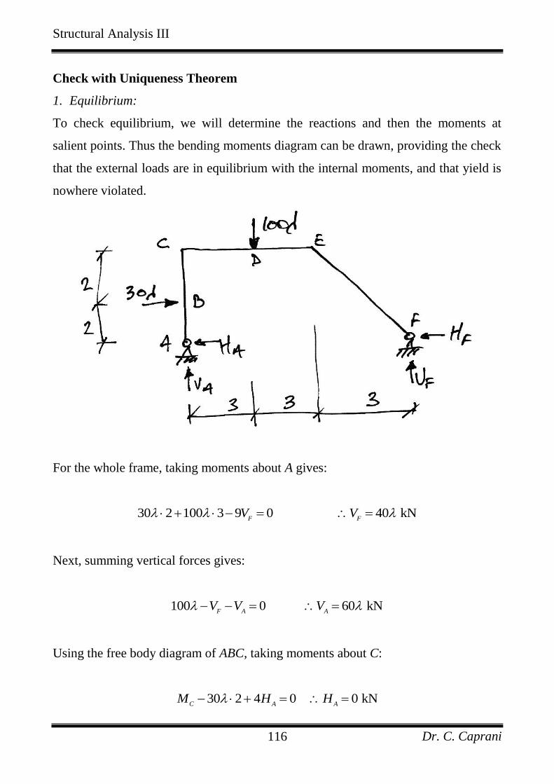
Structural Analysis III
Dr. C. Caprani 116
Check with Uniqueness Theorem
1. Equilibrium:
To check equilibrium, we will determine the reactions and then the moments at
salient points. Thus the bending moments diagram can be drawn, providing the check
that the external loads are in equilibrium with the internal moments, and that yield is
nowhere violated.
For the whole frame, taking moments about A gives:
30 2 100 3 9 0 40 kNF F
V V
Next, summing vertical forces gives:
100 0 60 kNF A A
V V V
Using the free body diagram of ABC, taking moments about C:
30 2 4 0 0 kNC A A
M H H
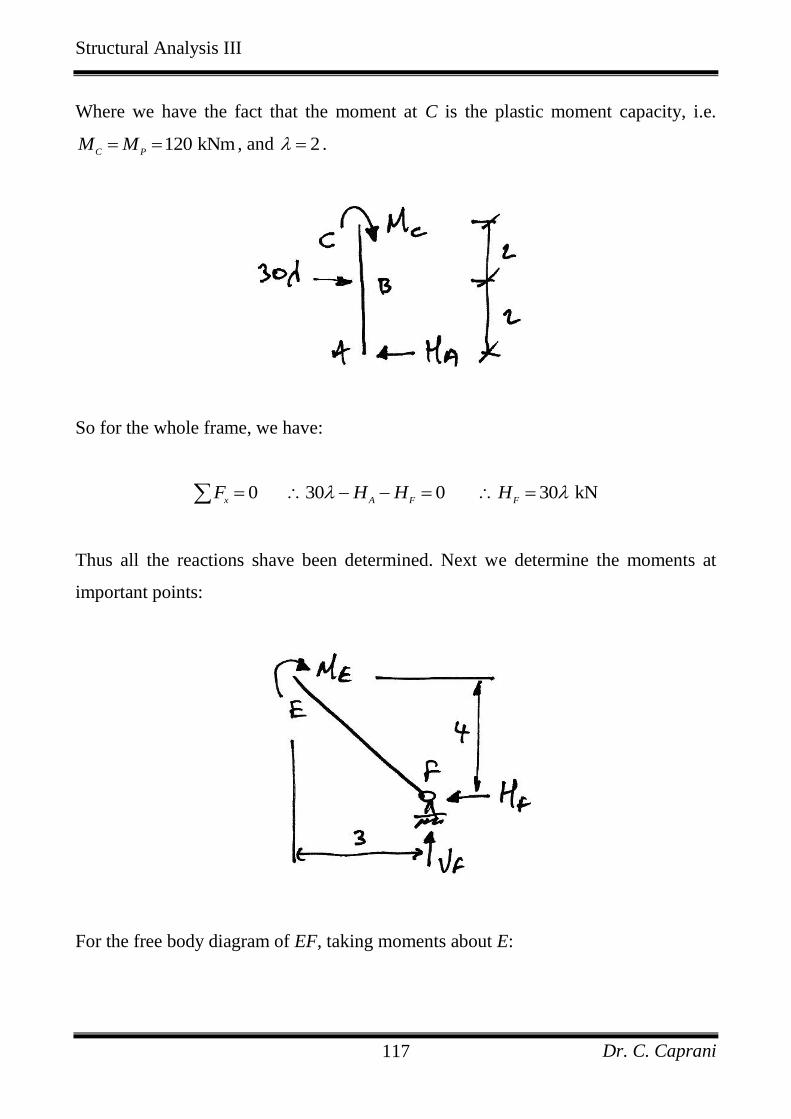
Structural Analysis III
Dr. C. Caprani 117
Where we have the fact that the moment at C is the plastic moment capacity, i.e.
120 kNmC P
M M , and 2 .
So for the whole frame, we have:
0 30 0 30 kNx A F F
F H H H
Thus all the reactions shave been determined. Next we determine the moments at
important points:
For the free body diagram of EF, taking moments about E:
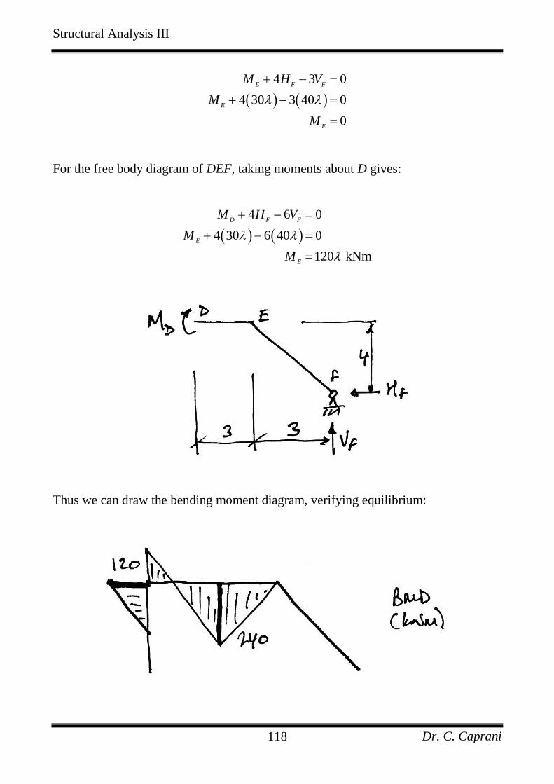
Structural Analysis III
Dr. C. Caprani 118
4 3 0
4 30 3 40 0
0
E F F
E
E
M H V
M
M
For the free body diagram of DEF, taking moments about D gives:
4 6 0
4 30 6 40 0
120 kNm
D F F
E
E
M H V
M
M
Thus we can draw the bending moment diagram, verifying equilibrium:
Structural Analysis III
Dr. C. Caprani 119
2. Mechanism:
Since 3 4 2 3 1R C we have a mechanism.
3. Yield:
The bending moment diagram at collapse shows that no section has a moment greater
than its moment capacity of either P
M or 2P
M :
Thus the requirements of the Uniqueness Theorem have been met, and so the collapse
load factor of 2 is the correct value.
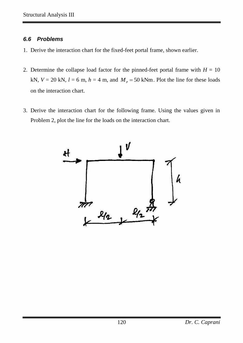
Structural Analysis III
Dr. C. Caprani 120
6.6 Problems
1. Derive the interaction chart for the fixed-feet portal frame, shown earlier.
2. Determine the collapse load factor for the pinned-feet portal frame with H = 10
kN, V = 20 kN, l = 6 m, h = 4 m, and 50 kNmP
M . Plot the line for these loads
on the interaction chart.
3. Derive the interaction chart for the following frame. Using the values given in
Problem 2, plot the line for the loads on the interaction chart.
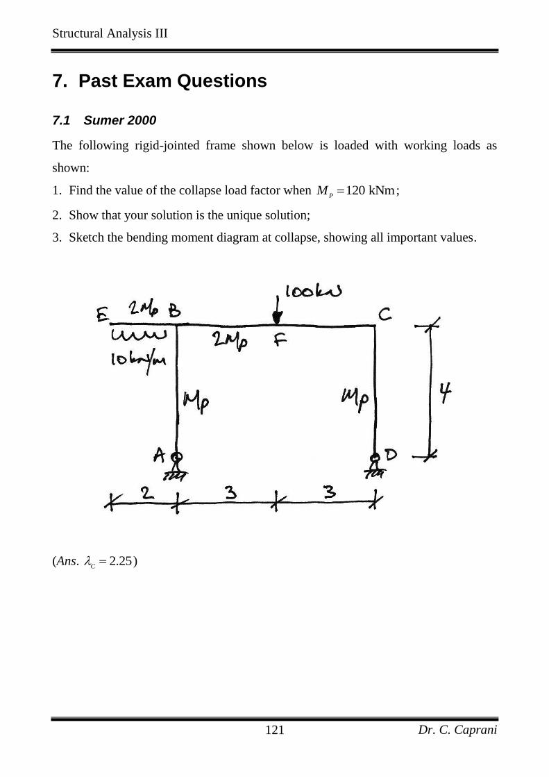
Structural Analysis III
Dr. C. Caprani 121
7. Past Exam Questions
7.1 Sumer 2000
The following rigid-jointed frame shown below is loaded with working loads as
shown:
1. Find the value of the collapse load factor when 120 kNmP
M ;
2. Show that your solution is the unique solution;
3. Sketch the bending moment diagram at collapse, showing all important values.
(Ans. 2.25C )
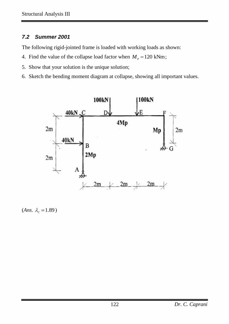
Structural Analysis III
Dr. C. Caprani 122
7.2 Summer 2001
The following rigid-jointed frame is loaded with working loads as shown:
4. Find the value of the collapse load factor when 120 kNmP
M ;
5. Show that your solution is the unique solution;
6. Sketch the bending moment diagram at collapse, showing all important values.
(Ans. 1.89C )
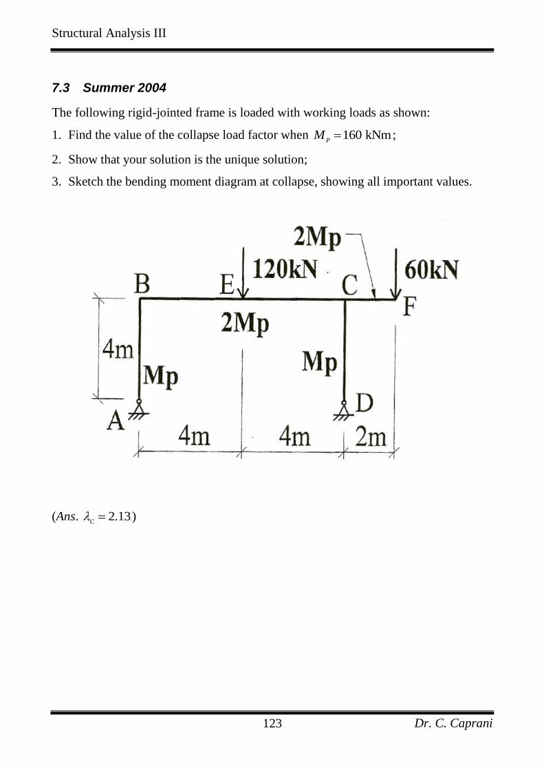
Structural Analysis III
Dr. C. Caprani 123
7.3 Summer 2004
The following rigid-jointed frame is loaded with working loads as shown:
1. Find the value of the collapse load factor when 160 kNmP
M ;
2. Show that your solution is the unique solution;
3. Sketch the bending moment diagram at collapse, showing all important values.
(Ans. 2.13C )
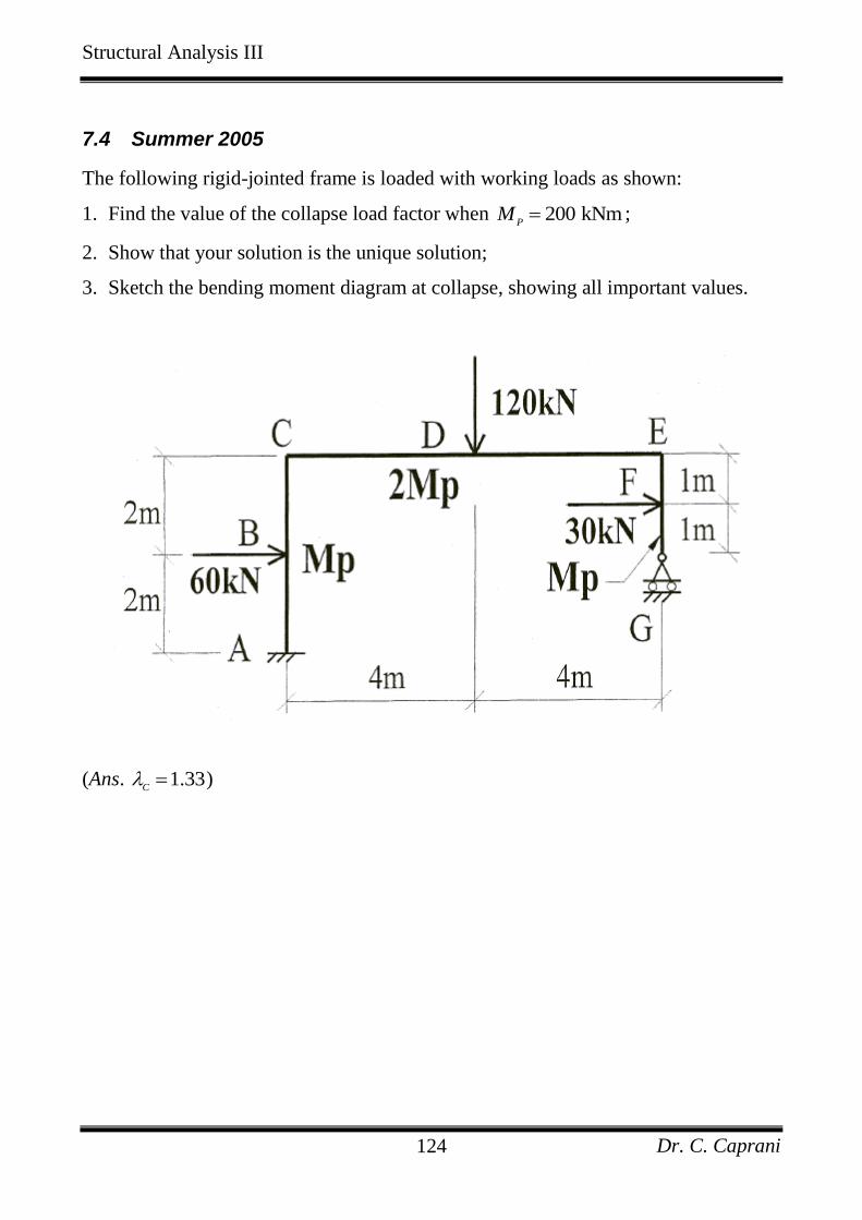
Structural Analysis III
Dr. C. Caprani 124
7.4 Summer 2005
The following rigid-jointed frame is loaded with working loads as shown:
1. Find the value of the collapse load factor when 200 kNmP
M ;
2. Show that your solution is the unique solution;
3. Sketch the bending moment diagram at collapse, showing all important values.
(Ans. 1.33C )
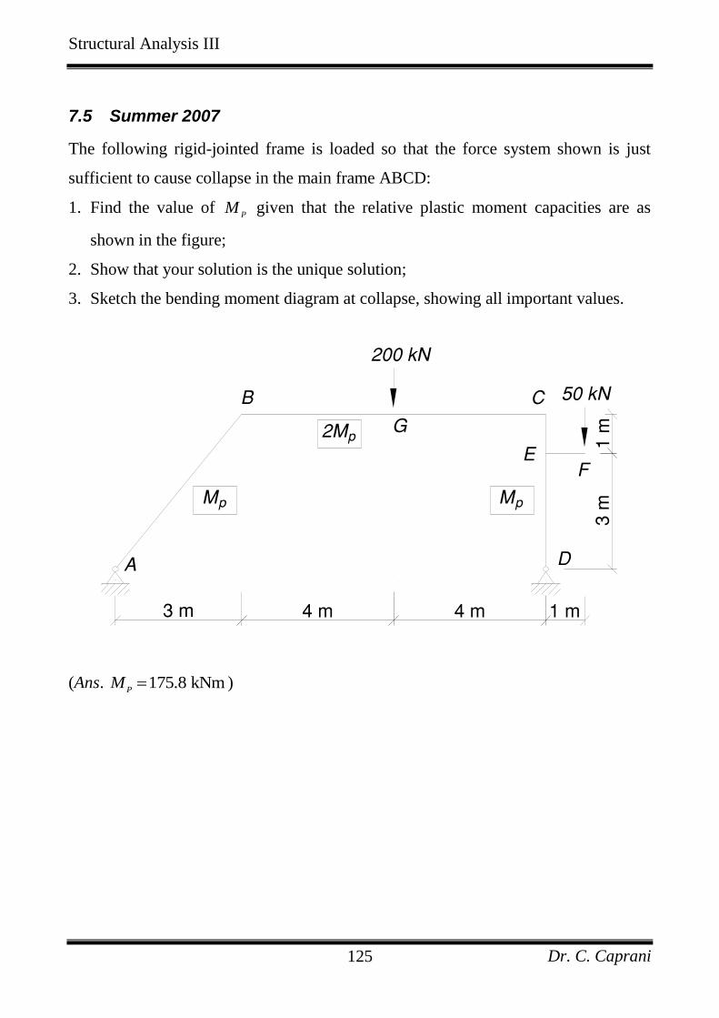
Structural Analysis III
Dr. C. Caprani 125
7.5 Summer 2007
The following rigid-jointed frame is loaded so that the force system shown is just
sufficient to cause collapse in the main frame ABCD:
1. Find the value of P
M given that the relative plastic moment capacities are as
shown in the figure;
2. Show that your solution is the unique solution;
3. Sketch the bending moment diagram at collapse, showing all important values.
FIG. Q5
(Ans. 175.8 kNmP
M )
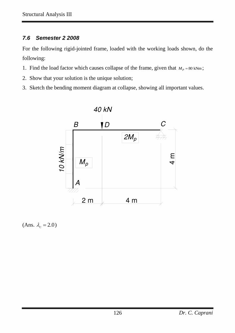
Structural Analysis III
Dr. C. Caprani 126
7.6 Semester 2 2008
For the following rigid-jointed frame, loaded with the working loads shown, do the
following:
1. Find the load factor which causes collapse of the frame, given that 80 kNmPM ;
2. Show that your solution is the unique solution;
3. Sketch the bending moment diagram at collapse, showing all important values.
FIG. Q3(a)
(Ans. 2.0C )
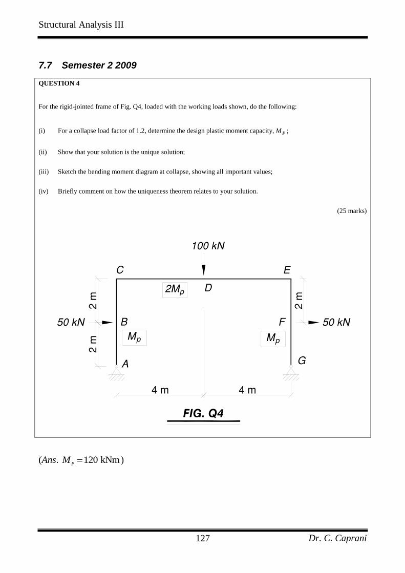
Structural Analysis III
Dr. C. Caprani 127
7.7 Semester 2 2009
QUESTION 4
For the rigid-jointed frame of Fig. Q4, loaded with the working loads shown, do the following:
(i) For a collapse load factor of 1.2, determine the design plastic moment capacity, PM ;
(ii) Show that your solution is the unique solution;
(iii) Sketch the bending moment diagram at collapse, showing all important values;
(iv) Briefly comment on how the uniqueness theorem relates to your solution.
(25 marks)
FIG. Q4
(Ans. 120 kNmP
M )
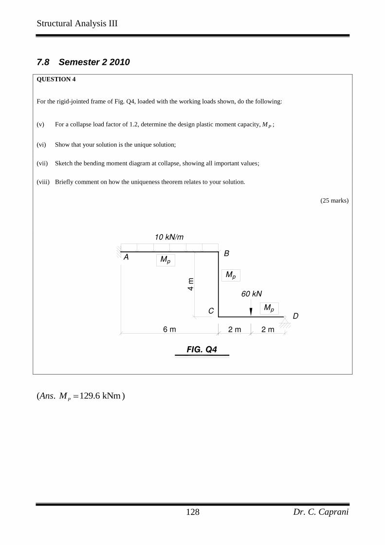
Structural Analysis III
Dr. C. Caprani 128
7.8 Semester 2 2010
QUESTION 4
For the rigid-jointed frame of Fig. Q4, loaded with the working loads shown, do the following:
(v) For a collapse load factor of 1.2, determine the design plastic moment capacity, PM ;
(vi) Show that your solution is the unique solution;
(vii) Sketch the bending moment diagram at collapse, showing all important values;
(viii) Briefly comment on how the uniqueness theorem relates to your solution.
(25 marks)
FIG. Q4
(Ans. 129.6 kNmP
M )
Structural Analysis III
Dr. C. Caprani 129
8. References
Baker, J.F., Horne, M.R. and Heyman, J., The Steel Skeleton, Volume II, Plastic
Behaviour and Design, Cambridge University Press, 1956.
Baker, J.F. and Heyman, J., Plastic Design of Frames, Vol. 1: Fundamentals,
Cambridge University Press, London, 1969.
Bruneau, M., Uang, C.M. and Whittaker, A., Ductile Design of Steel Structures,
McGraw-Hill, New York, 1998.
Davies, J.M. and Brown, B.A., Plastic Design to BS5950, Blackwell Science,
Oxford, 1996.
Heyman, J., Plastic Design of Portal Frames, Cambridge University Press,
London, 1957.
Heyman, J., Plastic Design of Frames, Vol. 2: Applications, Cambridge
University Press, London, 1971.
Heyman, J., Beams and Framed Structures, 2nd Edn., Pergamon Press, 1974.
Heyman, J., Elements of the Theory of Structures, Cambridge University Press,
1996.
Hodge, P.G., Plastic Analysis of Structures, McGraw-Hill, New York, 1959.
McKenzie, W.M.C., Examples in Structural Analysis, Taylor and Francis,
Abington, 2006.
Neal, B.G., Structural Theorems and their Applications, Pergamon Press, 1964.
Neal, B.G., The Plastic Methods of Structural Analysis, 3rd Edn., Chapman &
Hall, London, 1977.
Thompson, F., and Haywood, G.G., Structural Analysis Using Virtual Work,
Chapman and Hall, 1986.
Rees, D.W.A., Mechanics of Solids and Structures, Imperial College Press,
London, 2000.
Wong, M.B., Plastic Analysis and Design of Steel Structures, Butterworth-
Heinemann, London, 2009.