plant equipment heat exchangers - skills4success.cosaharapcc.skills4success.co/spcc/main/heat...
TRANSCRIPT
Plant Equipment
Heat ExchangersI n t e g r a t i o n a n d P r o f e s s i o n a l i s m
DR. ENG. MOHAMED AL-KHAWAGA
Update: November 2016
I N A C C O R D A N C E W I T H
TEMA STANDARD
HEAT EXCHANGER HANDBOOK
P L U S I N T E R N A T I O N A L C O D E S W H I C H P R O V I D I N G
P r a c t i c a l s o l u t i o n & A c a d e m i c S t u d i e s
P E T R O P R O J E C TI N T E R N A T I O N A L C O R P O R A T I O N
R E A L I S T I C I N N O VA T I O N
P R A C T I C A L S O L U T I O N
P R E FA C E
PROGRAM STRUCTURE AND GUIDANCEBODY OF KNOWLEDGE AND OVERVIEW
Eng. Mohamed Alkhawaga Nov. 016 2
P L A N T E Q U I P M E N T
HEAT EXCHANGERS

B o d y K n o w l e d g e
Module I.
PREFACE AND OVERVIEW
Heat Transfer Philosophy and methodology and other concepts
Module II.
H. EX. TYPES AND CLASSIFICATION
Illustration of H. Ex. Classification in depending on industries types and related to process targets
P L A N T E Q U I P M E N T
HEAT EXCGANGERS
I . PREFACE
Module III.
H. EX. DESIGN
Specific overview for all design recommendation
Module IV.
H. EX. Construction
Specific overview for all fabrication, Quality and installation gaudiness
Module V.
H. EX. MAINTENANCE
Specific overview for Inspection, repair and cleaning
O v e r v i e w
P L A N T E Q U I P M E N T
HEAT EXCHANGERS
I . PREFACE
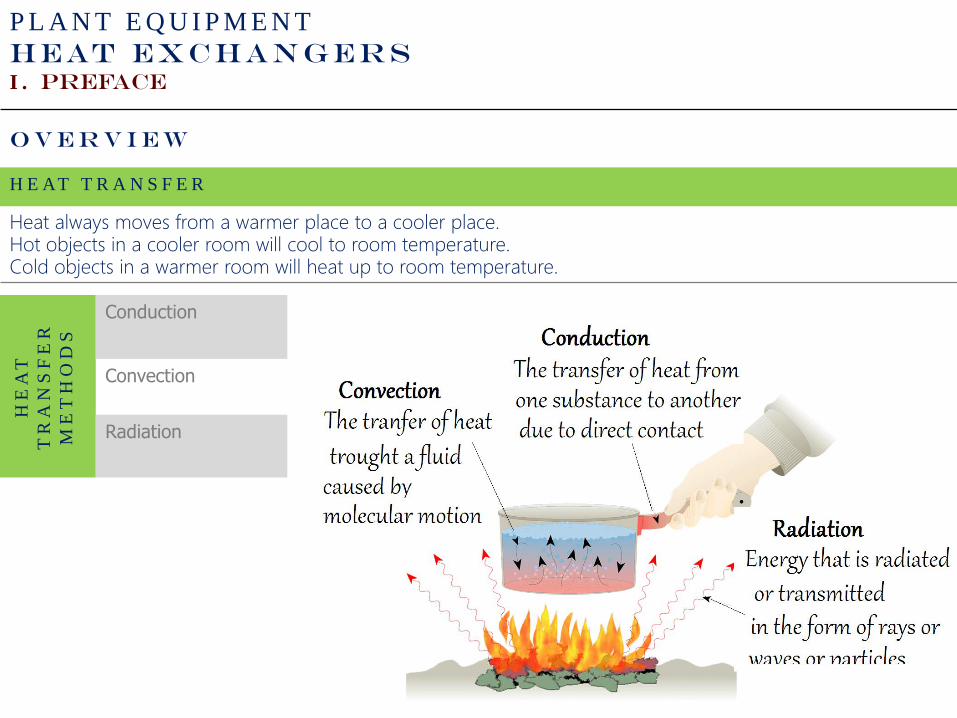
H E AT T R A N S F E R
Heat always moves from a warmer place to a cooler place.Hot objects in a cooler room will cool to room temperature.Cold objects in a warmer room will heat up to room temperature.
HE
AT
TR
AN
SF
ER
ME
TH
OD
S
Conduction
Convection
Radiation
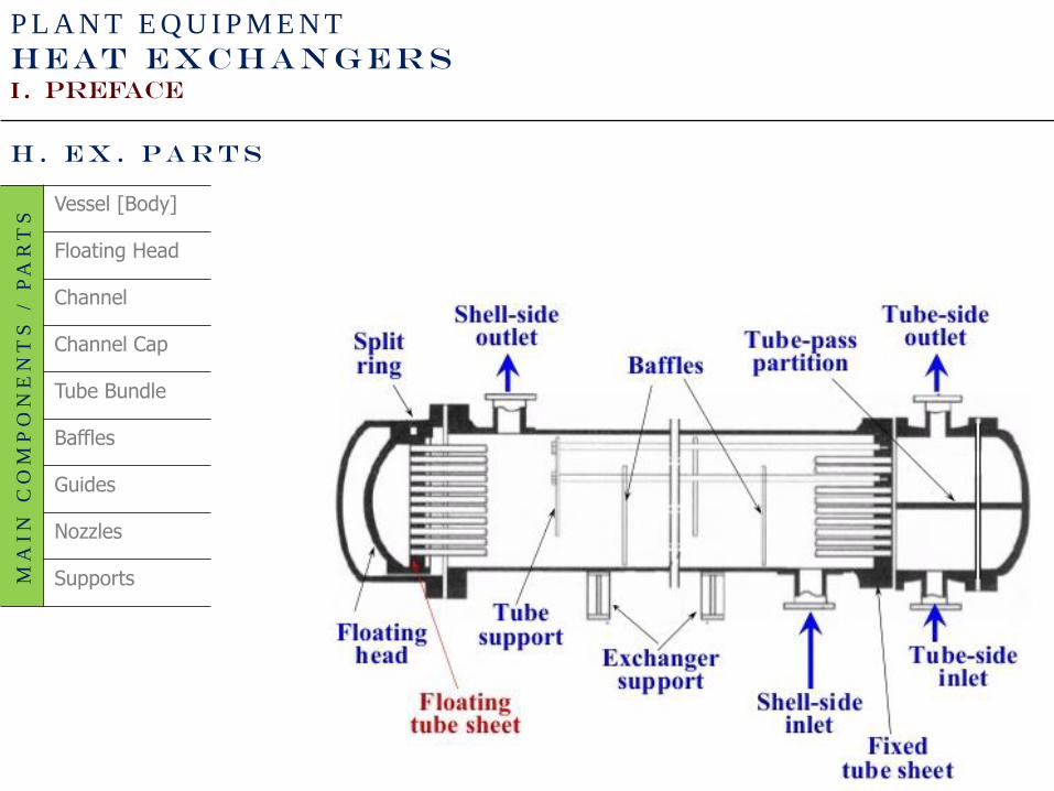
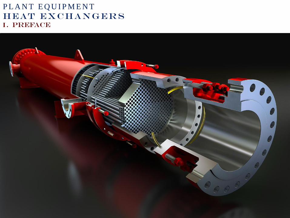
H . E X . P a r t s
P L A N T E Q U I P M E N T
HEAT EXCHANGERS
I . PREFACE
MA
IN
C
OM
PO
NE
NT
S / P
AR
TS
Vessel [Body]
Floating Head
Channel
Channel Cap
Tube Bundle
Baffles
Guides
Nozzles
Supports
P L A N T E Q U I P M E N T
HEAT EXCHANGERS
I . PREFACE
P L A N T E Q U I P M E N T
HEAT EXCHANGERS
I . PREFACE
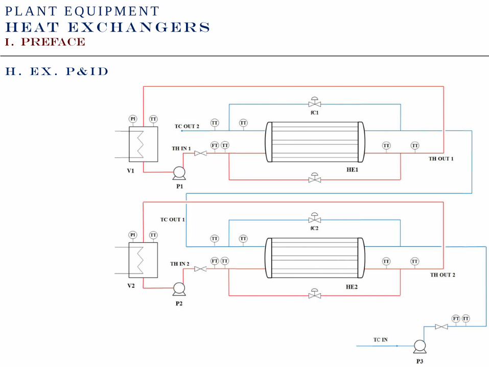
H . E X . P & I D
P L A N T E Q U I P M E N T
HEAT EXCHANGERS
I . PREFACE
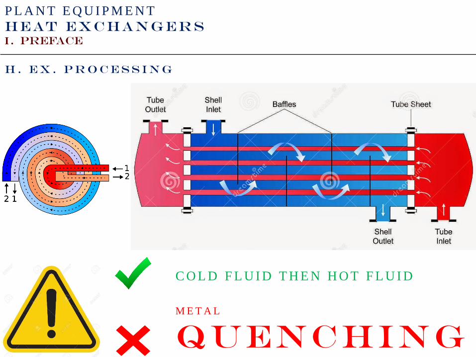
H . E X . P r o c e s s i n g
C O L D F L U I D T H E N H O T F L U I D
M E T A L
Quenching
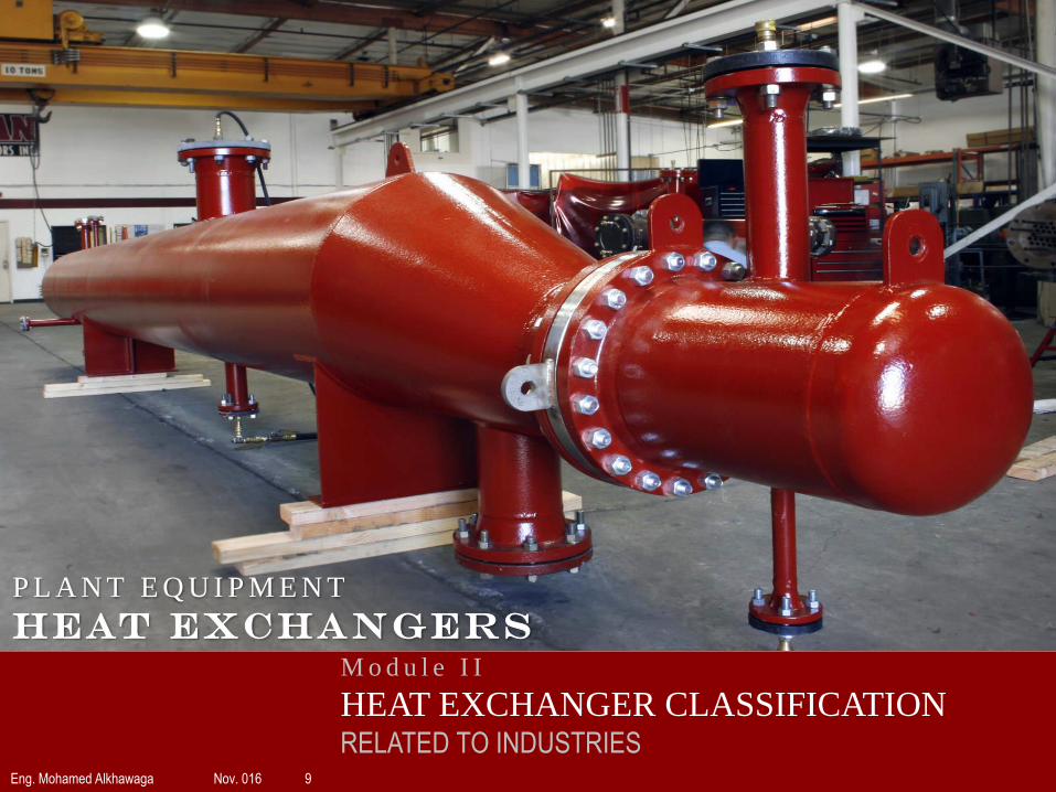
M o d u l e I I
HEAT EXCHANGER CLASSIFICATIONRELATED TO INDUSTRIES
Eng. Mohamed Alkhawaga Nov. 016 9
P L A N T E Q U I P M E N T
HEAT EXCHANGERS
P L A N T E Q U I P M E N T
HEAT EXCHANGERS
I . H. Ex. Classification
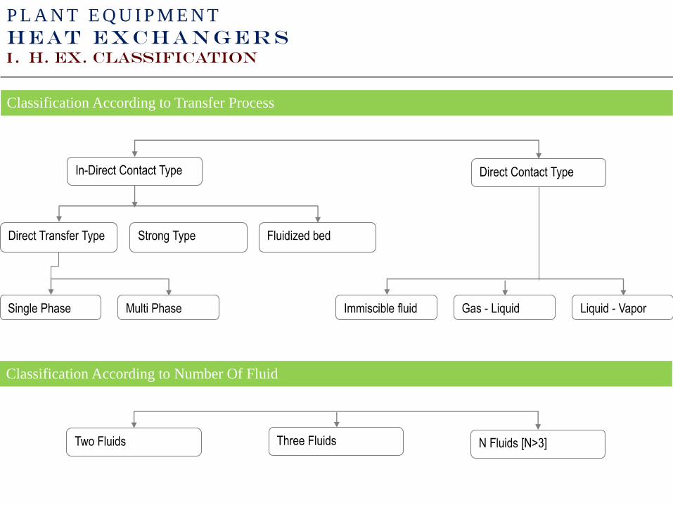
Classification According to Transfer Process
Direct Contact TypeIn-Direct Contact Type
Direct Transfer Type Strong Type Fluidized bed
Immiscible fluid Gas - Liquid Liquid - VaporSingle Phase Multi Phase
Classification According to Number Of Fluid
N Fluids [N>3]Two Fluids Three Fluids
P L A N T E Q U I P M E N T
HEAT EXCHANGERS
I . H. Ex. Classification
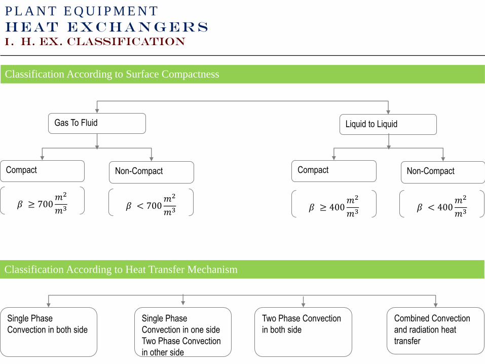
Classification According to Surface Compactness
Liquid to LiquidGas To Fluid
Compact Non-Compact
Classification According to Heat Transfer Mechanism
Combined Convection
and radiation heat
transfer
Single Phase
Convection in both side
Single Phase
Convection in one side
Two Phase Convection
in other side
Compact Non-Compact
𝛽 ≥ 700𝑚2
𝑚3 𝛽 < 700𝑚2
𝑚3 𝛽 ≥ 400𝑚2
𝑚3𝛽 < 400
𝑚2
𝑚3
Two Phase Convection
in both side
P L A N T E Q U I P M E N T
HEAT EXCHANGERS
I . H. Ex. Classification
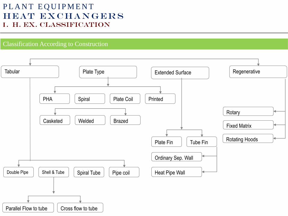
Classification According to Construction
RegenerativeTabular
Printed
Plate Type Extended Surface
PHA Spiral Plate Coil
Casketed Welded Brazed
Tube FinPlate Fin
Ordinary Sep. Wall
Heat Pipe Wall
Rotary
Fixed Matrix
Rotating Hoods
Pipe coilDouble Pipe Shell & Tube Spiral Tube
Parallel Flow to tube Cross flow to tube
P L A N T E Q U I P M E N T
HEAT EXCHANGERS
I . H. Ex. Classification
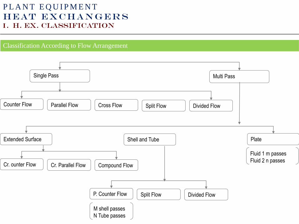
Classification According to Flow Arrangement
Multi PassSingle Pass
Counter Flow Parallel Flow
Extended Surface Plate
Cross Flow Split Flow Divided Flow
Fluid 1 m passes
Fluid 2 n passesCr. ounter Flow Cr. Parallel Flow Compound Flow
Shell and Tube
P. Counter Flow Split Flow Divided Flow
M shell passes
N Tube passes

P L A N T E Q U I P M E N T
HEAT EXCHANGERS
I . H. Ex. Classification
Concentric-Tube Heat Exchangers
Simplest configuration.
Superior performance associated with counter flow.
Parallel Flow Counterflow
P L A N T E Q U I P M E N T
HEAT EXCHANGERS
I . H. Ex. Classification
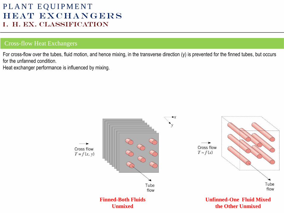
Cross-flow Heat Exchangers
For cross-flow over the tubes, fluid motion, and hence mixing, in the transverse direction (y) is prevented for the finned tubes, but occurs
for the unfanned condition.
Heat exchanger performance is influenced by mixing.
Finned-Both Fluids
Unmixed
Unfinned-One Fluid Mixed
the Other Unmixed

PLANT EQUIPMENT
HEAT EXCHANGERS
II. H. EX. CLASSIFICATION
Shell-and-Tube Heat Exchangers
Baffles are used to establish a cross-flow and to induce turbulent mixing of the shell-side fluid, both of which enhance convection.
The number of tube and shell passes may be varied, e.g.:
One Shell Pass, Two Tube Passes Two Shell Passes, Four Tube Passes
PLANT EQUIPMENT
HEAT EXCHANGERS
II. H. EX. CLASSIFICATION
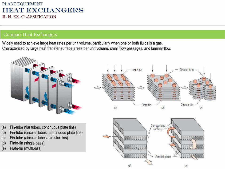
Compact Heat Exchangers
Widely used to achieve large heat rates per unit volume, particularly when one or both fluids is a gas.
Characterized by large heat transfer surface areas per unit volume, small flow passages, and laminar flow.
(a) Fin-tube (flat tubes, continuous plate fins)
(b) Fin-tube (circular tubes, continuous plate fins)
(c) Fin-tube (circular tubes, circular fins)
(d) Plate-fin (single pass)
(e) Plate-fin (multipass)
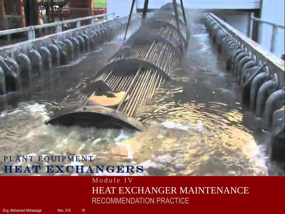
M o d u l e I V
HEAT EXCHANGER MAINTENANCERECOMMENDATION PRACTICE
Eng. Mohamed Alkhawaga Nov. 016 18
P L A N T E Q U I P M E N T
HEAT EXCHANGERS
19
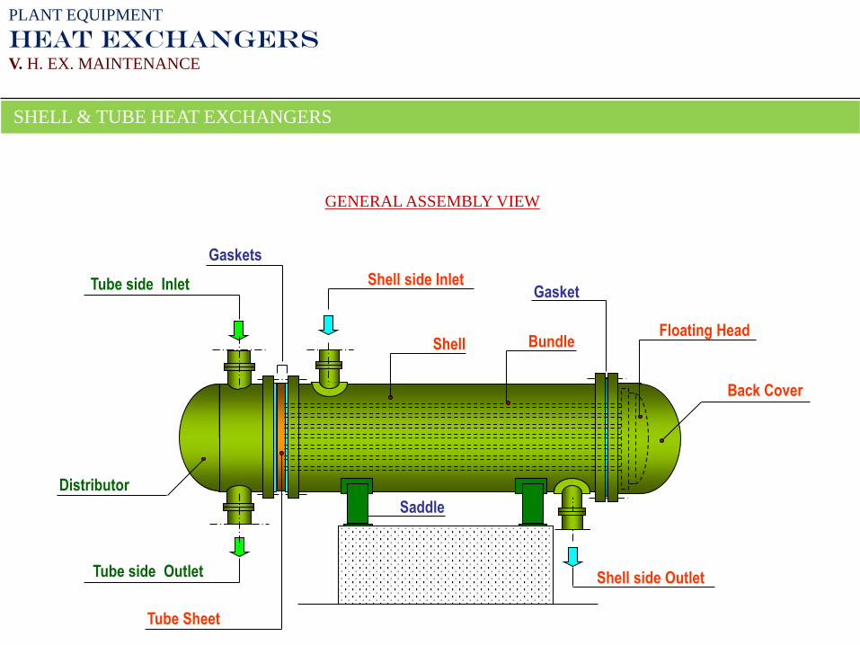
GENERAL ASSEMBLY VIEW
Shell side Inlet
Shell side Outlet
Tube side Inlet
Tube side Outlet
Shell
Back Cover
Distributor
Tube Sheet
Gaskets
Gasket
Saddle
Floating HeadBundle
PLANT EQUIPMENT
HEAT EXCHANGERS
V. H. EX. MAINTENANCE
SHELL & TUBE HEAT EXCHANGERS
20
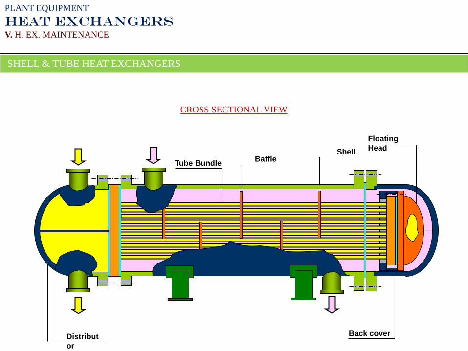
CROSS SECTIONAL VIEW
BaffleShell
Distribut
or
Back cover
Tube Bundle
Floating
Head
PLANT EQUIPMENT
HEAT EXCHANGERS
V. H. EX. MAINTENANCE
SHELL & TUBE HEAT EXCHANGERS
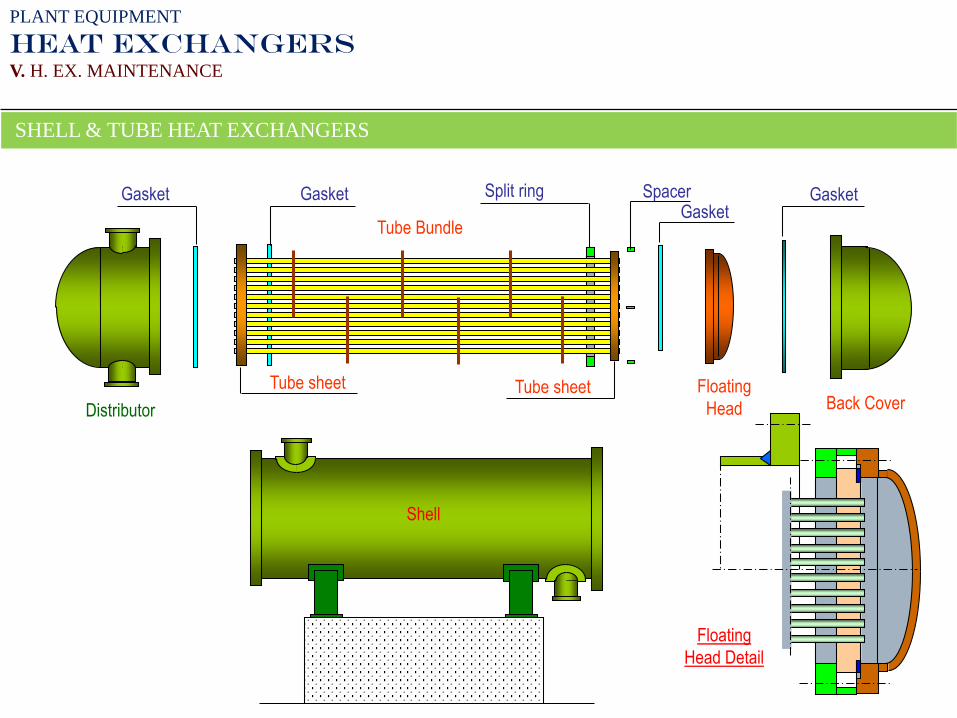
21
Split ring
Distributor Back CoverFloating
Head
GasketSpacerGasket GasketGasket
Shell
Floating
Head Detail
Tube Bundle
Tube sheet Tube sheet
PLANT EQUIPMENT
HEAT EXCHANGERS
V. H. EX. MAINTENANCE
SHELL & TUBE HEAT EXCHANGERS

22
Do Not Start The Job Without A Safety Plan
23
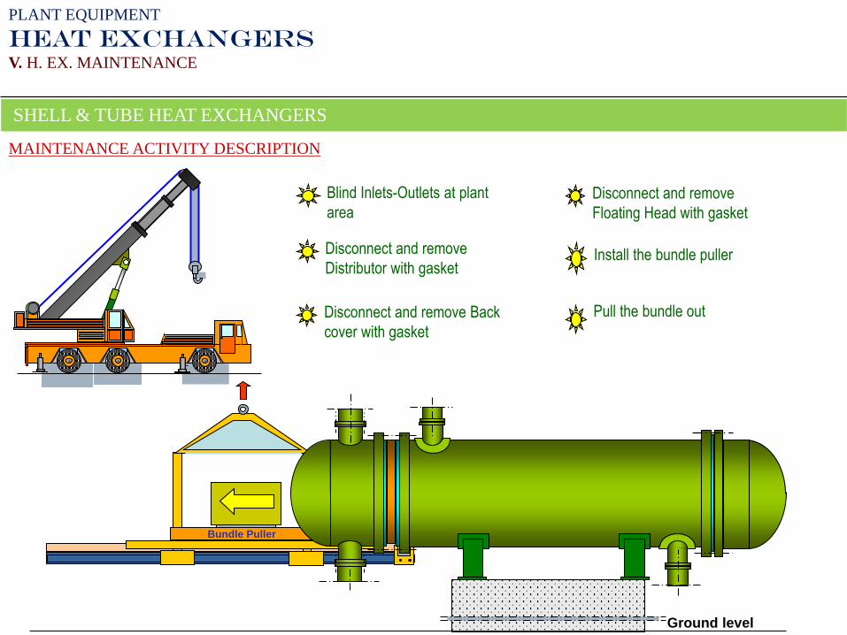
Bundle Puller
MAINTENANCE ACTIVITY DESCRIPTION
Blind Inlets-Outlets at plant
area
Disconnect and remove
Distributor with gasket
Disconnect and remove Back
cover with gasket
Disconnect and remove
Floating Head with gasket
Install the bundle puller
Pull the bundle out
Ground level
PLANT EQUIPMENT
HEAT EXCHANGERS
V. H. EX. MAINTENANCE
SHELL & TUBE HEAT EXCHANGERS
24
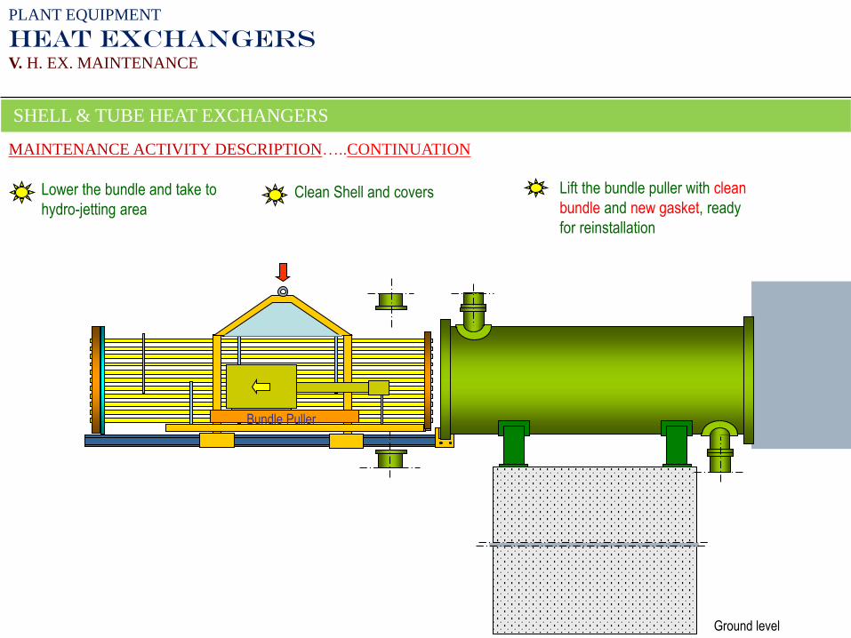
Bundle Puller
MAINTENANCE ACTIVITY DESCRIPTION…..CONTINUATION
Clean Shell and covers Lift the bundle puller with clean
bundle and new gasket, ready
for reinstallation
Lower the bundle and take to
hydro-jetting area
Ground level
PLANT EQUIPMENT
HEAT EXCHANGERS
V. H. EX. MAINTENANCE
SHELL & TUBE HEAT EXCHANGERS
25
Bundle Puller
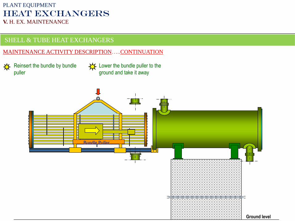
MAINTENANCE ACTIVITY DESCRIPTION…..CONTINUATION
Reinsert the bundle by bundle
puller
Lower the bundle puller to the
ground and take it away
Ground level
PLANT EQUIPMENT
HEAT EXCHANGERS
V. H. EX. MAINTENANCE
SHELL & TUBE HEAT EXCHANGERS
26
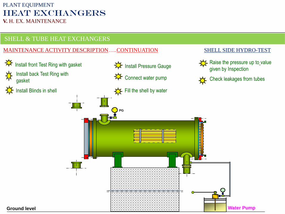
MAINTENANCE ACTIVITY DESCRIPTION…..CONTINUATION
Install front Test Ring with gasket
Install back Test Ring with
gasket
Fill the shell by water
Install Pressure Gauge
Ground level
SHELL SIDE HYDRO-TEST
PG
Install Blinds in shell
Water Pump
Connect water pump Check leakages from tubes
Raise the pressure up to value
given by Inspection
PLANT EQUIPMENT
HEAT EXCHANGERS
V. H. EX. MAINTENANCE
SHELL & TUBE HEAT EXCHANGERS
Water
Water
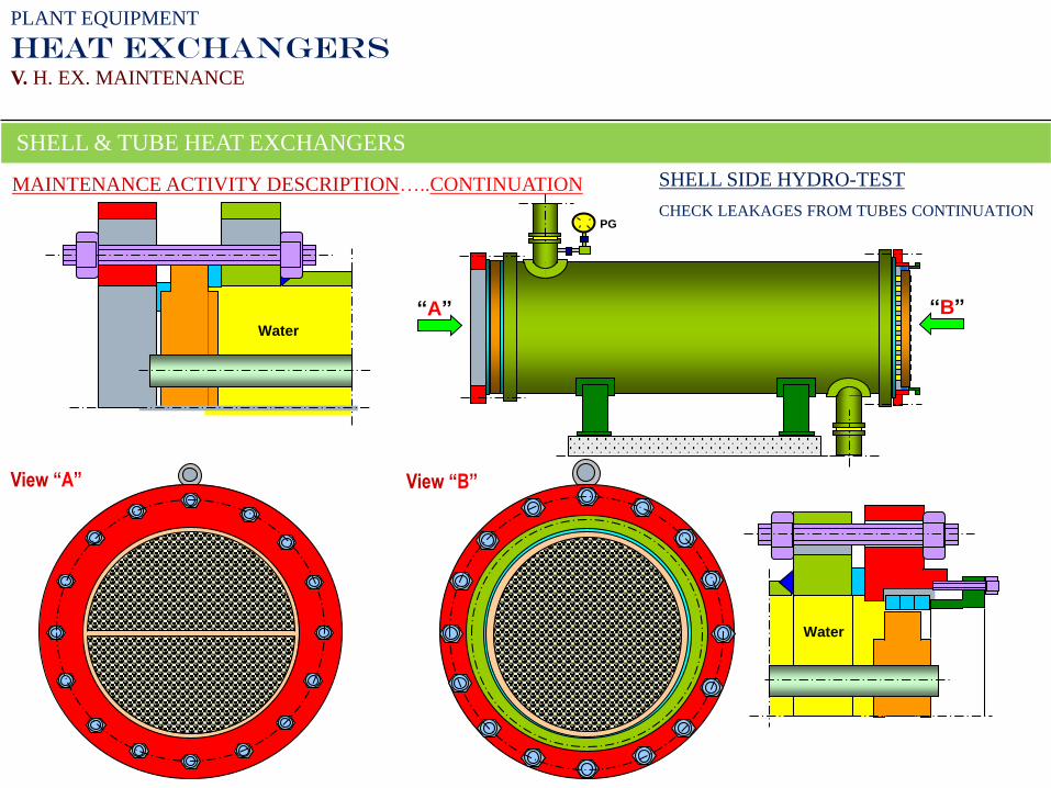
SHELL SIDE HYDRO-TEST
CHECK LEAKAGES FROM TUBES CONTINUATIONPG
“A” “B”
View “B”View “A”
PLANT EQUIPMENT
HEAT EXCHANGERS
V. H. EX. MAINTENANCE
SHELL & TUBE HEAT EXCHANGERS
MAINTENANCE ACTIVITY DESCRIPTION…..CONTINUATION
28
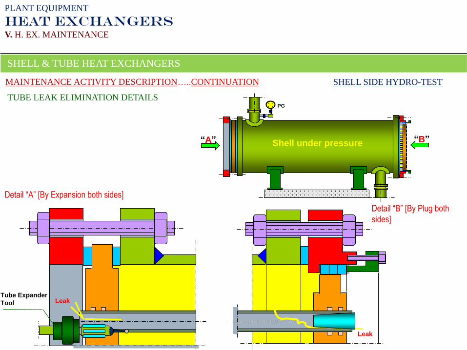
TUBE LEAK ELIMINATION DETAILS
Detail “B” [By Plug both
sides]
Detail “A” [By Expansion both sides]
Leak
Leak
SHELL SIDE HYDRO-TEST
Tube Expander
Tool
PG
“A” “B”Shell under pressure
MAINTENANCE ACTIVITY DESCRIPTION…..CONTINUATION
PLANT EQUIPMENT
HEAT EXCHANGERS
V. H. EX. MAINTENANCE
SHELL & TUBE HEAT EXCHANGERS
29
PG
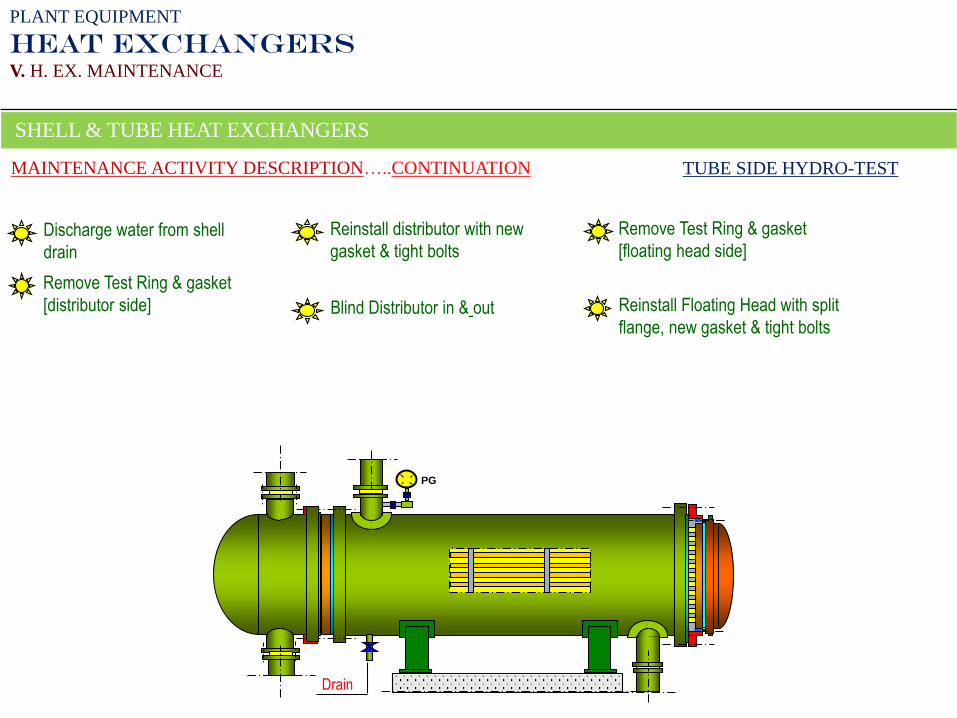
Remove Test Ring & gasket
[distributor side]
Reinstall distributor with new
gasket & tight bolts
Remove Test Ring & gasket
[floating head side]
Reinstall Floating Head with split
flange, new gasket & tight bolts Blind Distributor in & out
Discharge water from shell
drain
Drain
PLANT EQUIPMENT
HEAT EXCHANGERS
V. H. EX. MAINTENANCE
SHELL & TUBE HEAT EXCHANGERS
MAINTENANCE ACTIVITY DESCRIPTION…..CONTINUATION TUBE SIDE HYDRO-TEST
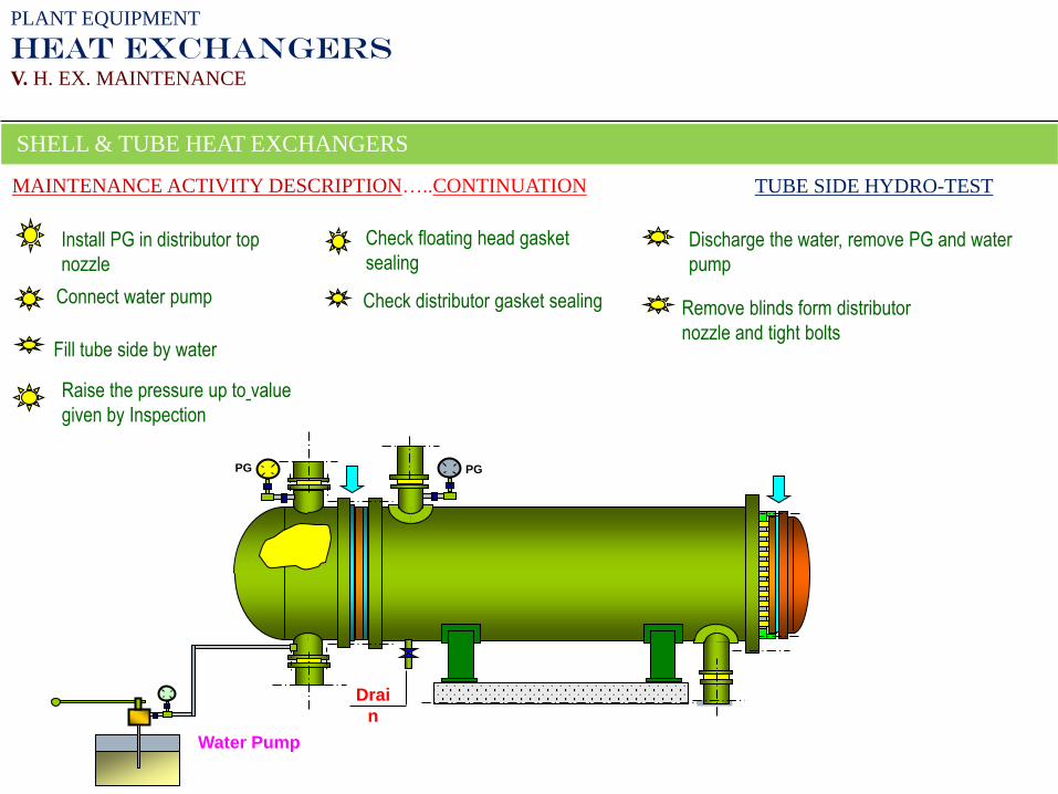
PG
Check distributor gasket sealing
Check floating head gasket
sealing
PG
Fill tube side by water
Drai
n
Install PG in distributor top
nozzle
Connect water pump
Water Pump
Raise the pressure up to value
given by Inspection
Discharge the water, remove PG and water
pump
Remove blinds form distributor
nozzle and tight bolts
PLANT EQUIPMENT
HEAT EXCHANGERS
V. H. EX. MAINTENANCE
SHELL & TUBE HEAT EXCHANGERS
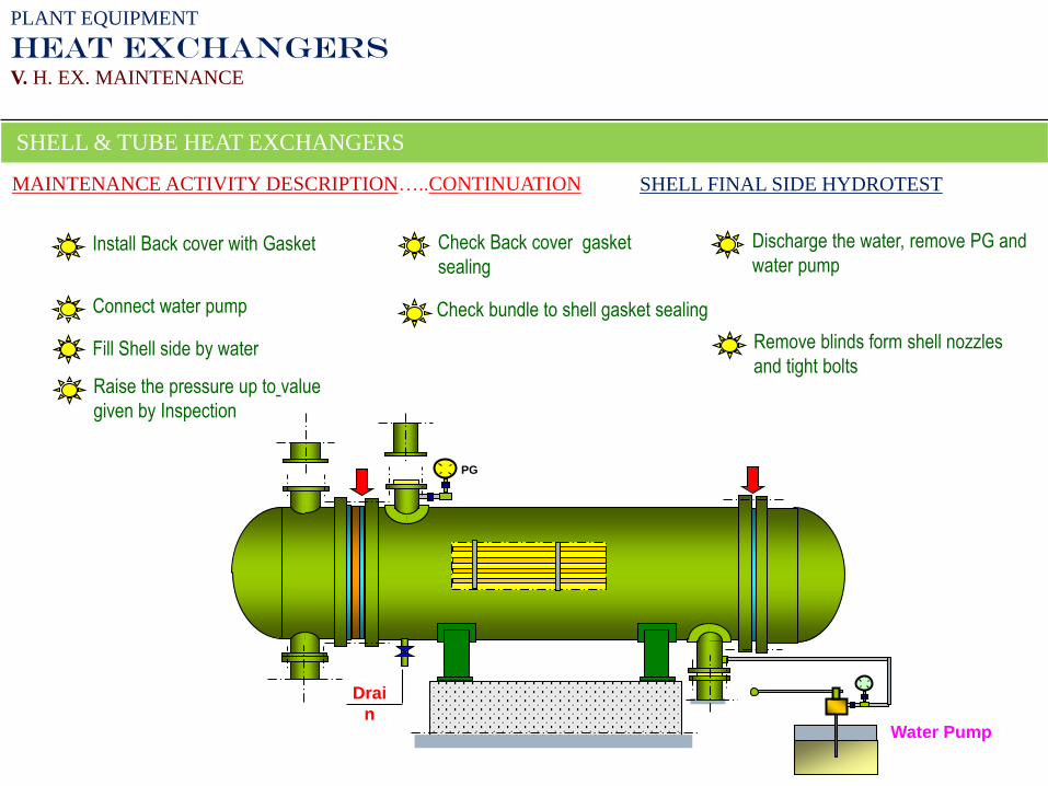
MAINTENANCE ACTIVITY DESCRIPTION…..CONTINUATION TUBE SIDE HYDRO-TEST
31
PG
Check bundle to shell gasket sealing
Check Back cover gasket
sealing
Fill Shell side by water
Drai
n
Install Back cover with Gasket
Water Pump
Raise the pressure up to value
given by Inspection
Discharge the water, remove PG and
water pump
Remove blinds form shell nozzles
and tight bolts
Connect water pump
PLANT EQUIPMENT
HEAT EXCHANGERS
V. H. EX. MAINTENANCE
SHELL & TUBE HEAT EXCHANGERS
MAINTENANCE ACTIVITY DESCRIPTION…..CONTINUATION SHELL FINAL SIDE HYDROTEST
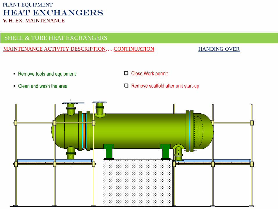
Close Work permit Remove tools and equipment
Clean and wash the area Remove scaffold after unit start-up
PLANT EQUIPMENT
HEAT EXCHANGERS
V. H. EX. MAINTENANCE
SHELL & TUBE HEAT EXCHANGERS
MAINTENANCE ACTIVITY DESCRIPTION…..CONTINUATION HANDING OVER