pid wall follower
DESCRIPTION
This is the documentation for the PID Wall Follower built during the Winter Workshop 2009 at IIT Kharagpur by Technology Robotix Society.TRANSCRIPT

KRAIG Winter Workshop 2009
PID WALL FOLLOWER
Heads:
Pratyush Pande
Mahtab Singh Soin
Group Members:
Samarth Mahajan
Abhishek Choudhary
Sayan Deya
Pranav Raina
Shourav Chakravarti
Kranthi Kiran
Ananth
Chaitanya
Akhilesh
Nikhil
INTRODUCTION
Problem statement-
To develop an autonomous robot which is capable of wall following using PID control.
OVERALL DESCRIPTION
1.General layout-
There are 5 main parts of the bot, namely-
1. The rectifier
2. Sensory module
3. Microcontroller
4. Motor driver circuit
5. Actuators
The rectifier provides a 12 volt DC to the microcontroller unit. The sensors consist of
LED-LDR circuits. The microcontroller unit is responsible for the autonomous
maneuvering of the bot and controls the motor driver circuit. Motor driver circuit consists
of an L293D. The motors are the actuators used.
2.Software specifications
The C program operating the microcontroller was written for the wall follower using
CodeVisionAVR.

BASICS OF PID-
The PID controller algorithm involves three separate parameters; the proportional, the
integral and derivative values. The proportional value determines the reaction to the
current error, the integral value determines the reaction based on the sum of recent errors,
and the derivative value determines the reaction based on the rate at which the error has
been changing. The weighted sum of these three actions is used to adjust the process via a
control element such as the position of a control valve or the power supply of a heating
element.
Proportional term-
The proportional term (sometimes called gain) makes a change to the output that is
proportional to the current error value. The proportional response can be adjusted by
multiplying the error by a constant Kp, called the proportional gain.
The proportional term is given by:
where
Pout: Proportional term of output
Kp: Proportional gain, a tuning parameter
e: Error
t: Time or instantaneous time (the present)
Integral term-
The contribution from the integral term (sometimes called reset) is proportional to both
the magnitude of the error and the duration of the error. Summing the instantaneous error
over time (integrating the error) gives the accumulated offset that should have been

corrected previously. The accumulated error is then multiplied by the integral gain and
added to the controller output. The magnitude of the contribution of the integral term to
the overall control action is determined by the integral gain, Ki.
The integral term is given by:
where
Iout: Integral term of output
Ki: Integral gain, a tuning parameter
e: Error
t: Time or instantaneous time (the present)
τ: a dummy integration variable
Derivative term-
The rate of change of the process error is calculated by determining the slope of the error
over time (i.e., its first derivative with respect to time) and multiplying this rate of change
by the derivative gain Kd. The magnitude of the contribution of the derivative term
(sometimes called rate) to the overall control action is termed the derivative gain, Kd.
The derivative term is given by:
where
Dout: Derivative term of output
Kd: Derivative gain, a tuning parameter
e: Error
t: Time or instantaneous time (the present)
The proportional, integral, and derivative terms are summed to calculate the output of the
PID controller. Defining u(t) as the controller output, the final form of the PID algorithm
is:

where the tuning parameters are:
Proportional gain, Kp
Larger values typically mean faster response since the larger the error, the larger
the proportional term compensation. An excessively large proportional gain will
lead to process instability and oscillation.
Integral gain, Ki
Larger values imply steady state errors are eliminated more quickly. The trade-off
is larger overshoot: any negative error integrated during transient response must
be integrated away by positive error before reaching steady state.
Derivative gain, Kd
Larger values decrease overshoot, but slow down transient response and may lead
to instability due to signal noise amplification in the differentiation of the error.
HARDWARE-
1. The rectifier-
The rectifier circuit converts the 220 volt AC power supply into a 12 V DC supply.
It consists of the following 3 parts:
Step Down Transformer
It converts the 220V AC power into 12 V AC output.
Bridge rectifier
It is basically a full wave rectifier which consists of 4 diodes and an electrolytic
capacitor.
As the diodes conduct only in forward bias so when the input connected to the left corner
is negative, and the input connected to the right corner is positive, current flows from

the upper terminal to the lower terminal through the capacitor. Similarly when the
polarities at the left and right corners is reversed the direction of current remains same.
The capacitor provides a low impedance path to the AC component of the output,
reducing the AC voltage across, and AC current through, the resistive load. In less
technical terms, any drop in the output voltage and current of the bridge tends to be
canceled by loss of charge in the capacitor. This charge flows out as additional current
through the load. Thus the noise is reduced.
IC7812
The function of this 3 pin IC is to provide a smooth supply of 12 volt DC without any
ripples.
In this figure, the left pin is the input pin, the middle one is the ground and the right pin is
the output pin.
2. Sensors-
The sensors we’ve used are LED-LDR sensors. Instead of one branch of LED and a
resistor in series ( as shown in the figure), we’ve used 12 such branches in parallel for the
proper sensing by the LDR. The output of the sensor goes into the 8-BIT ADC which is
provided by the port A of the micro controller.
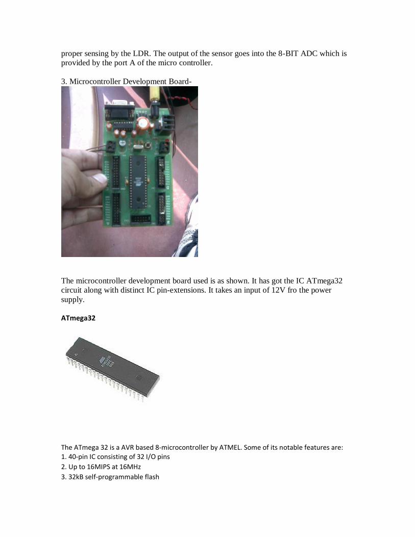
3. Microcontroller Development Board-
The microcontroller development board used is as shown. It has got the IC ATmega32
circuit along with distinct IC pin-extensions. It takes an input of 12V fro the power
supply.
ATmega32
The ATmega 32 is a AVR based 8-microcontroller by ATMEL. Some of its notable features are: 1. 40-pin IC consisting of 32 I/O pins
2. Up to 16MIPS at 16MHz
3. 32kB self-programmable flash

4. 2kB internal SRAM
5. 1024 Bytes EEPROM
6. Two 8-bit timers and one 16-bit timer
7. 8 channel,10-bit ADC
The pin diagram of ATmega32 is as shown in the figure.
3.Motor Driver Circuit- The motor-driver circuit is an electronic circuit that links the microcontroller to the actuators. The output digital signal sent by the ATmega32 is implemented by the circuit. It essentially consists of the IC L293D, the pin diagram of which is shown in the figure. The ‘Enable’ pins when set high, initiate the functioning of the I/O pins on their respective sides. This can also be used to implement PWM. The Vcc pin input is the voltage the IC needs for its functioning (5V for L293D) while the Vss pin input is the voltage at which the connected motors work. Here we are driving the DC motors of our robot at 12V power supply.

Both inputs low – motor halt First output high, second output low – motor forward First output low, second output high – motor reverse Both inputs high – motor halt
In the motor-driver circuit we have used 4 2-pin connecters and 2 3-pin connecters. The top-left and top-right connecters are for the Vcc and Vss pins respectively. The left 3-pin connecter connects to the enable (pin 1), input a (pin 2) and input b (pin 7) of the IC. Similarly the right 3-pin connecter connects to the enable (pin 9), input c (pin 10) and input d (pin 15) of the IC. Pins

3 and 6 are the outputs to the left DC motor through the bottom-left 2-pin connecter and pins 11 and 14 to the right motor through the bottom-right 2-pin connecter.
4.Motors We have used 2 DC motors with gear-systems in our robot. Both are 100RPM motors that run at a 12V power supply.
THE MAKING OF THE ROBOT
1. The power supply-
We first made our own rectifier circuit. We converted the 220V AC input voltage to 12V
AC using a step down transformer. Then this 12V AC was converted to 12V DC using a
rectifier having diodes and electrolytic capacitor on a dotted PCB. Note that it is better to
use a dotted PCB than a line PCB as it gives us more compactness. Be careful while
connecting the capacitor and the diodes. The capacitor has to be connected with proper
polarity and the current through the diodes flows from black to grey.
2. The motor driver circuit-
Then came the motor driver circuit. We first soldered the base of IC L293D to the PCB.
Then we neatly soldered the four 2 pin and two 4 pin relimates as we couldn’t find any 3
pin relimates! We kept one pin dysfunctional.
3. The sensors-
In total we used 4 sensors. Each sensor had 12 LED’s, 1 LDR, twelve 330 ohm resistors
and a 330 k ohm resistor. We used white LED’s and a 330 ohm resistor was kept in series
with each LED so that the LED doesn’t blow out because of it’s low resistance. The 330
k ohm resistor was kept in series with the LDR for proper thresholding. Firstly we had
used two sensors on the sides of the bot, but as it couldn’t detect inclined and front walls,
we made two more such sensors and placed them on the front side.
4. The development board-
Next came the most critical part-the development board. The output from the sensors was
given to Port A which we used as ADC.
Pin Sensor
PA0 – left backward
PA1 – right backward
PA2 – left forward
PA3 – right forward
We used port B as the output port for motor driver circuit. We connected
Connections b/w Port B and L293D circuit

1. PB0 to pin 1
2. PB1 to pin2
3. PB2 to pin7
4. PB3 to pin9
5. PB4 to pin10
6. PB5 to pin15 Firstly we used the internal 5V provided by the development board to power the sensors and L293D. This resulted in excessive heating of the IC7812 in the power supply. The sensors also started flickering as they were getting less power. So we used another External 5V supply to power the sensors and L293D.
5. Assembling of the bot-
The final task was to assemble the bot. We used a wooden frame consisting of two levels.
We put the development board on the upper level and stuck the motor driver circuit on
the lower one. The motor driver circuit powers two motors which drive the wheels. An
independent castor wheel is also provided at the front end. We used two rectifier circuits
– one for 12V DC which powers the development board and acts as Vss for the motor
driver circuit and one 5V supply which powers the sensors and the Vcc of the motor
driver circuit (for L293D).
ALGORITHMS IMPLIMENTED:
The basic aim of the problem statement was to make the path taken by the wall follower
as smooth as possible by implementing the PID controller.
1. First we came up with a simple algorithm which could simply follow the desired path
(navigating our arena), although not in a smooth manner .This basically helped us to find
the appropriate threshold values for all the four sensors which we used in the other codes
that were made later.
The bot simply calculates the difference between the left and right sensor voltages (the
error) that are received by the ADC and turns in one direction (either a zero radius turn or
a single motor powered turn) based on the sign of the error.

(We used an 8 bit ADC in this code)
The step by step algorithm
a) In this algorithm, the front sensors are activated (take control of the motors) only when
the wall comes very near to it i.e. when the error value of the forward sensors lies within
a certain threshold zone. The threshold was set by measuring the voltage given by the
sensor at the given range (using a multimeter) and then converting the value to the digital
scale of the 8 bit timer.
The output to the motors when the front sensors are activated is a zero radius turn in the
desired direction based on the sign of the error.
b) If at any point of time the error lies outside the threshold zone of the front sensors the
bot is controlled by both the rear sensors.
For certain small range of error which is very close to zero, the bot is simply made to go
forward. This is done to accommodate the small difference between the full range
voltages of the two rear sensors and to reduce the overshoot.
c) If however the error lies outside this range, only one of the motors is powered and the
supply to the other motor is turned off, resulting in a turn. The direction again is based on
the sign of the error given by the rear sensors.
Observation: An important thing that came out while writing this code was the range of
voltage given by the two front sensor was drastically different although identical LDRs &
LEDs were used to make them both. This significantly complicated the implementation
of our other codes.
2. In the next algorithm, we had to implement a proportional controller. Here also, the
MicroC computes an error based on the sensor inputs and gives outputs the motor based
on its sign .But here the quantity ‘error’ is based on the outputs of all the four sensors and
also, here the output to the motor depends on the value of the error as well (proportional).
The value of the error had to be calculated giving a certain weightage to the error given
by the front and the rear sensors. This weightage was given by introducing two constants
(a and b). But furthermore, the value of error given by the two front sensors cannot be
calculated directly by calculating the difference between their voltages as their ranges are
different (seen while implementing the previous algorithm). So again the voltage from
one sensor had to be scaled up to make it nearly comparable to the other sensor value and
then the difference had to be estimated. This was done using the constants K1 & K2.
So, finally the error was calculated as
ERROR= a*((o/p rear right sensor)-(o/p rear left sensor)) +
b*(K1(o/p front right sensor)-K2(o/p front left sensor))

Now the motors had to be provided power proportional to this error. This was achieved
by giving a sort of PWM using delay functions. The motors, in the different error
conditions (checked by an if-else statement within an infinite while loop), are powered
(by setting the output pins on the port high) and then a delay is given whose value is
proportional to the error. The last statement in the while loop provides an output to stall
both the motors and provides some constant delay (done basically to slow down the
motors).
But since the delay functions do not allow variable inputs, we had to generate our own
delay functions using a while loop with dummy variables which served our purpose.
Step by step algorithm
a) When the error lies outside a given threshold range, the proportional delay is provided
to a zero radius turn output which is given based on the sign of the error.
b) Within this range, the proportional delay is provided to an output which powers only
one motor based on the sign of the error.
In this algorithm we decided to use the 10 bit ADC to improve the accuracy of the
threshold values. This did in fact improve the bot.
The estimation of the different constants a, b, K1 and K2 had to be done almost
purely on the basis of trial and error.
3. The third and final algorithm that we tried was a PD controller. Here the value of the power
provided to the motors to turn the bot is not only proportional to the value of the error itself but
also to the rate of change of the error (differential).
The implementation of this algorithm was almost totally similar to the previous in terms of the
error calculation and the estimation of the constants. Here one extra proportionality constant
had to be introduced for the differential of the error.
a) In the infinite while loop the starting updates the value of the current error based on the ADC
inputs and the end of the loop stores this value as the previous error (preverror) which is then
used to calculate the differential.
b)The other motor outputs are exactly same as the previous algorithm.