physical layer network coding for next generation wireless broadband
DESCRIPTION
Physical layer network coding for next generation wireless broadband. Alister Burr, University of York [email protected] Agisilaos Papadogiannis, Chalmers University. Outline. The challenge of next generation wireless networks Next generation network architectures MIMO and MIMO cellular - PowerPoint PPT PresentationTRANSCRIPT

11th March 2010 1
Physical layer network coding for next generation
wireless broadband
Alister Burr, University of [email protected]
Agisilaos Papadogiannis, Chalmers University

11th March 2010 2
Outline
The challenge of next generation wireless networks
Next generation network architectures MIMO and MIMO cellular Multi-user and Network MIMO Physical layer network coding Conclusions

11th March 2010 3
Wireless networks – some history
Began with Marconi in 1890’s … 1st generation
analogue, telephony ~1980 (Japan) 2nd generation
digital, some data ~1992 3rd generation
CDMA, flexible services, up to 384 kbit/s ~2002 4th generation
OFDM(A), full Internet access, up to 1 Gbit/s ???
11th March 2010 4
4G
The “next generation” has been discussed ever since 3G standards were finalised a decade ago however it was not initially clear what form the
“fourth generation” might take However starting from 2002 ITU-R has defined the
requirements for IMT-Advanced which has since then been generally accepted as
the definition of 4G Key requirement is 100 Mbit/s for high mobility and
1 Gbit/s for low mobility Standards currently under development:
Mobile WiMAX (IEEE 802.16e/m) 3GPP LTE-Advanced

11th March 2010 5
The dream
To provide full Internet connectivity to everyone, anywhere which means wirelessly
Next generation wireless research has usually focussed on a ‘headline’ maximum data rate but of course this will not be the rate most users
experience, and probably is not the most important figure In densely-populated cities a network for everyone
must provide extremely high capacity densities

11th March 2010 6
Required capacity density
Average population density in European cities ranges from 3400 - 5400/km2
however in commercial district in working hours it will be much higher
say 8000/km2
Suppose 10% subscribe, and 20% of those require access at busy hour
Expected data rate 5 Mbit/s8000/km2 10% 20% 5 Mbit/s = 800 Mbit/s/km2

11th March 2010 7
Capacity density of 1G
e.g. AMPS, U.S.A: ~400 channels in each direction ~15 km radius cells 700 km2
re-use ~1:10 0.06 channels/km2, equivalent to approx 1.8 kbit/s/km2
in approx 50 MHz

11th March 2010 8
Current and 4G systems
Currently one base station serves about 1km2
4G bandwidths proposed are ~ 40 MHz Best available bandwidth efficiency averages
about 2 bits/s/Hz across cell hence capacity density is 80 Mbit/s/km2
assumes 100% frequency re-use We need an order of magnitude more! 10 more bandwidth unlikely to be available

11th March 2010 9
Increased density
We can also increase number of cells
BUT need many
more cell sites interference

11th March 2010 10
Cell edge problem
We may be able to increase bandwidth efficiency (bits/s/Hz) use (e.g) advanced MIMO
techniques BUT mobile close to cell
edge suffers interference from adjacent cells
Conventionally we reduce frequency re-use but this reduces available
bandwidth by factor 3 or more
11th March 2010 11
BuNGee
University of York is part of a European project tackling these problems Beyond Next Generation Mobile Broadband
(BuNGee) Proposes:
new hierarchical network architecture based on wireless backhaul
Advanced MIMO techniques for high bandwidth efficiency
Self-organising network for optimal spectrum use
Goal: 1 Gbit/s/km2

11th March 2010 12
Outline
The challenge of next generation wireless networks
Next generation network architectures MIMO and MIMO cellular Multi-user and Network MIMO Physical layer network coding Conclusions

11th March 2010 13
Achieving capacity density
Will probably need a combination of the approaches mentioned: More spectrum Improved bandwidth efficiency
especially increased use of MIMO Increased frequency re-use (100%) Reduced cell size
requires low base station installation cost, and a cost-effective backhaul network

11th March 2010 14
Wireless backhaul
Simple comparison with 4G proposals suggests we may need ~10 BSs per km2!
We believe that the only cost-effective way to provide this is by wireless backhaul
However must allow for spectrum used by backhaul links
Hence must minimise backhaul load

11th March 2010 15
BuNGee architecture

11th March 2010 16
Some figures
Assume HBS serves 1 km2
Assume total 40 MHz available 20 MHz for MS-ABS (access links); 20 MHz ABS-HBS (backhaul)
Assume average 2 bits/s/Hz across cell Then capacity per ABS = 20 2 = 40 Mbit/s No. ABS per HBS = 1 Gbit/s / 40 Mbit/s = 25 Area served by ABS = 1 km2/25 = 40 000 m2, or
200m square

11th March 2010 17
Wireless mesh network
Since cells are very small, mobile (MS) may be
served by more than one ABS
MSs now served by optimum combination of available ABSs
Practically abolishes concept of cells!
Overall network looks more like a wireless mesh network
HBS
ABS
MS
Relay
MS
ABS
ABS

11th March 2010 18
Wireless relaying
A cell can be extended by adding fixed, or infrastructure relays very similar
architecture to wireless backhaul
with relays replacing ABSs
may allow direct connection of MSs to hub
RelayRelay

11th March 2010 19
Hierarchical wireless network
A generalised framework for network architectures involving wireless backhaul and/or relaying
we might allow: more than one layer of
relays direct connections between
nodes on the same level MSs to connect to different
relay levels Again, similar to mesh
network in structure

11th March 2010 20
Outline
The challenge of next generation wireless networks
Next generation network architectures MIMO and MIMO cellular Multi-user and Network MIMO Physical layer network coding Conclusions

11th March 2010 21
MIMO link model
MIMO = Multiple Input, Multiple Output i.e. multiple antennas at each end of a link
Input and output signal can be modelled as (1 nT) and (1 nR) vectors, s and r; noise (1 nR): n
channel modelled as a matrix H: element Hij gives propagation between transmit antenna j and receive antenna i
r = H s + n
ENCODER
DECODER
H11
H21
HnR1
s r
Tn
nR

11th March 2010 22
Eigendecomposition
s' UH
n
VHsr
r'
nTnR
n1
n
Multiply by matrices U and V at input and output of channel, where
columns of U,V are transmit and receive eigenvectors of the channel
Then U H VH =
a diagonal matrix with the square roots of the eigenvalues of HHH on the diagonal, and r’i = i s’i + n’i
i.e. we create a set of uncoupled channels, whose power gains are the eigenvalues
Each eigenvector can be treated as a steering vector for antenna array transmit/receive beam patterns

11th March 2010 23
Beamforming model
Another way of viewing MIMO: each input stream corresponds to a beam from the
antenna array towards a multipath signal can create as many such beams as there are antennas hence can transmit up to n = min(nT, nR) beams
provided there are enough multipaths
s' U VH r'
n

11th March 2010 24
MIMO capacity
Capacity and bandwidth efficiency approximately multiplied by no. of streams, n
Slope of curves proportional to n called multiplexing
gain Dramatic capacity
gain!
0 5 10 15 20 25 300
5
10
15
20
25
30
35Rayeigh capacity
SNR(dB)
Cap
acity
(bi
ts/s
/Hz)
nT=4 nR=4nT=2 nR=4
nT=1 nR=4
nT=4 nR=2
nT=2 nR=2
nT=4 nR=1nT=1 nR=1

11th March 2010 25
MIMO in interference
MIMO cellular system also subject to interference Beamformer applies linear weights to maximise
SNIR at output filters signals from different directions to maximise
signal to noise-plus-interference ratio
s
sint dint
d
r x
H
H int
W V
U
Uint
matched filter
n
d̂
Beamformer

11th March 2010 26
Capacity of MIMO cellular
4 antenna elements
MIMO system capacity around 3 SISO
and more than 1.5 SIMO (smart antenna)
Beamformer (“prewhitening”) very important
Interference limited

11th March 2010 27
Implications for 4G networks
MIMO can dramatically increase link capacity and significantly increase cellular capacity Note that capacity is mainly affected by
n = min(nT, nR)
Still severely limited by inter-cell interference
Can we reduce the effect of interference?

11th March 2010 28
Outline
The challenge of next generation wireless networks
Next generation network architectures MIMO and MIMO cellular Multi-user and Network MIMO Physical layer network coding Conclusions

11th March 2010 29
Multi-user MIMO systems
It has been known since the 1960s that the optimum means of sharing a channel between several users may be by simultaneous, mutually interfering transmission as opposed to time-division multiplexing, or
other orthogonal multiplexing Information-theoretic approach:
Multiple Access Channel - MAC (uplink) Broadcast Channel - BC (downlink)

11th March 2010 30
2-user SISO MAC
Rate region: set of achievable rates of the two sources
C1 and C2 are capacities of two channels without the other
“Corner points” achieved by successive interference cancellation
“Time sharing” sum rate limited to dashed line in general achievable sum
rate Csum exceeds this
1 1 1 2 2 1
2 2 2 1 2 2
1 2 1 2
2 1 2
; log 1
; log 1
, ;
log 1
sum
R C I X Y X P N
R C I X Y X P N
R R C I X X Y
P P N
R1
R2
C2
C1
Csum
time-sharingrate

11th March 2010 31
Multi-user MIMO MAC
In a multi-user MIMO multiple access channel (uplink), sum rate capacity limit is capacity of MIMO channel
formed by combining all Tx antennas of all users
For nU users with nT Tx antennas, average Tx power Si and Tx time Ti (each)
where:
denotes capacity of nTnR MIMO channel with SNR S
, ,1
, ,1
1 U
T R T R
UU T R U T R
n
TS i n n i n nii
nsum n n n i n n ni
TC T C S C S
T T
C C S C S
1 1; ;U Un ni ii iS S T T
,T Rn nC S

11th March 2010 32
Multi-user MIMO
Conventional TDMA/FDMA is equivalent to time-sharing divides “headline” rate by no. of channels
MU-MIMO allows several users to share same time slot/channel
Users/BS can act as a single nT nU nR MIMO system
Usually more BS than terminal antennas multiplexing gain no
longer limited by no. terminal antennas
BS
nR
nT
nU

11th March 2010 33
Symmetric and asymmetric
Modest advantage when nT = nR (symmetric links) Large advantage when nT nR (asymmetric links)
max. multiplexing gain becomes min(nR, nTnU)
0 5 10 15 20 25 300
10
20
30
40
50
60
70
80
SNR (dB)
Cap
acity
(bi
ts/s
/Hz)
Sum rate (black) and time-share capacity (red), 8 users, nT=2, nR=8
0 5 10 15 20 25 300
5
10
15
20
25
30
35
40
SNR (dB)
Cap
acity
(bits
/s/H
z)
Sum rate (black) and time-share capacity (red), 8 users, nT=4, nR=4

11th March 2010 34
Broadcast channel
Broadcast channel simply means one transmitter to many receivers obvious example is radio/TV broadcasting, where
same message is intended for all also applies to cellular downlink, where a different
message is intended for each receiver In latter case can define a
capacity region like that for multi-user MIMO
Again time sharing (TDMA/FDMA) is sub-optimal
R1
R2
C2
C1
Csum
time-sharingrate

11th March 2010 35
Dirty paper coding (DPC)
This is an information-theoretic result which applies to a channel subject to interference where the interference is known at the transmitter r = s + i + n where s is the information signal, i is the interference, and n is
noise Achievable capacity of this channel is
log2(1 + PS/Pn) i.e. the same capacity as if the interference were not present note this is not achieved by “pre-cancelling” the interference
On a broadcast downlink, the signal to one user is interference to another, and is known at the transmitter

11th March 2010 36
Precoding in practice
Dirty paper precoding in principle operates by selecting a codebook (set of transmitted codewords) depending on the interference
A more practical scheme following the same principle is Tomlinson-Harashima precoding (THP)
Use modulo function f(x), and transmit: where d is data, i is interference and
k is some integer At the receiver apply the modulo
operation again: interference is removed some degradation due to “folding” of
noise
A
f(x)
x
mod ,2 2
A Af x x A
s f d i d i kA
d f r f s i n
f d n kA
d n k A

11th March 2010 37
Linear beamforming
Or simpler still, we can simply form beams to each user ensuring also that we null interference to other
users this is a purely linear operation

11th March 2010 38
Network MIMO
So far we have assumed that signals from other cells must be treated as interference
However it is possible for several (in principle, all) base stations to cooperate to transmit to a given mobile
or to receive from that mobile Then there is in principle no CCI!
since all received signals are exploited as signals
The entire system then operates as a multi-user MIMO system with (on the uplink) nTnU nC transmit and nRnC receive antennas
where nC is the number of cooperating cells
in principle multiplexing gain approaches min(nRnC, nTnU nC)

11th March 2010 39
Practical limitations
There are of course practical limitations to this concept: Where should the processing be performed?
In a hierarchical network like BuNGee, at the hub Distributed methods also possible, with processing
at cooperating BSs Computational complexity
Synchronisation Is it feasible to keep cooperating base stations
phase synchronous? (especially for downlink) Backhaul capacity

11th March 2010 40
Backhaul capacity requirements
On the downlink, if two BSs cooperate to communicate with an MS, that MS’s data should be sent to both could double backhaul requirements
On the uplink, neither may be able to decode the MS without the signal from the other hence analogue signal may need to be
transmitted over the backhaul in high precision
may increase backhaul requirements by several times
Need to ensure backhaul links are efficiently used
r1r2
a1r1 + a2r2
s1 s2
b2s2b1s1

11th March 2010 41
Limitations of in-band backhauling
If we use wireless backhaul, we must account for bandwidth occupied
Can we re-use the same spectrum in backhaul and access segments? in-band backhauling
Duplexing restrictions of ABSs usually prevent same resources being used in the two segments in the same place

11th March 2010 42
Outline
The challenge of next generation wireless networks
Next generation network architectures MIMO and MIMO cellular Multi-user and Network MIMO Physical layer network coding Conclusions

11th March 2010 43
Network coding
A network node applies a joint coding function to two (or more) incoming data streams instead of simply switching between
them In this simple example (the “butterfly
network”) the central node applies the XOR function (modulo-2 addition) then both streams can be recovered
at both output nodes without network coding the central
link would have to have twice the capacity to achieve this

11th March 2010 44
Two-way relay channel (2WRC)
Allows a relay to support transmissions in two directions at once
Relay broadcasts XOR combination of two incoming streams
Each destination can then reconstruct data intended for it by XOR combination with the data it transmitted
SA
DB
RSB
DA
a b
a ba b

11th March 2010 45
Physical layer network coding (PLNC)
In a wireless network, we do not have discrete, non-interfering paths except by using TDMA or FDMA
Signals: are broadcast to all nodes within range combine additively in signal space
However it is still possible to extract a joint information stream equivalent to XOR combination

11th March 2010 46
PLNC for 2WRC
System operates in two phases Phase 1: sources transmit
simultaneously Phase 2: relay transmits
Assume both sources transmit BPSK {+1, -1} {1, 0}
SA
DB R
SB
DA
a b
a ba b
a + b
0+211
1001
1010
0-200
a ba+bba
SA, SB
SA, SB
time
Phase 1 Phase 2

11th March 2010 47
For comparison
Without network coding
Network layer network coding
Physical layer network coding
SA
DB
RSB
DA
a b
a ba b
time
SA
R(A)
SB
R(B)
time
SA SB
R(AB)
time
SA, SB
R(AB)

11th March 2010 48
Relay data compression
Cooperative diversity: relay provides extra diversity if S – D link fades
Phase 1: Source transmits to relay and destination Phase 2: Relay transmits to destination Note signal at relay is correlated with Phase 1 signal at
destination since both arise from the same data
This allows distributed compression using Slepian-Wolf coding reduces the data relay must transmit
S
R
D

11th March 2010 49
Slepian-Wolf coding
If two data sources are correlated, their joint information content is less than the sum of their separate content
Can exploit this to compress the data even though encoders
are separate White area on graph gives
rate region range of possible
compressed rates to allow reconstruction
S1
R1
R2
C1
D
S2 C2
S’1
S’2
R1
R2

11th March 2010 50
PLNC in network MIMO
Example: 2 terminals connected
to hub via 3 BS B2 can use PLNC, to share
its link with the hub betweentwo terminals
It can use distributed compression, since the data is correlated with that via B1 and B3
Reduces backhaul load
T1 T2
B1 B2 B3
Hub

11th March 2010 51
Two-way relaying in hierarchical wireless network
Duplexing constraints can be alleviated using 2-way relaying allows access and backhaul
resource to be shared at each ABS however neighbouring ABSs and
corresponding MSs may interfere We have analysed this
considering a simple scenario Assume 2 ABSs share resources
over 2 slots i.e. both ABSs and MSs transmit
simultaneously on same channel consider amplify-and-forward and
network coded decode-and-forward relaying
11th March 2010 52
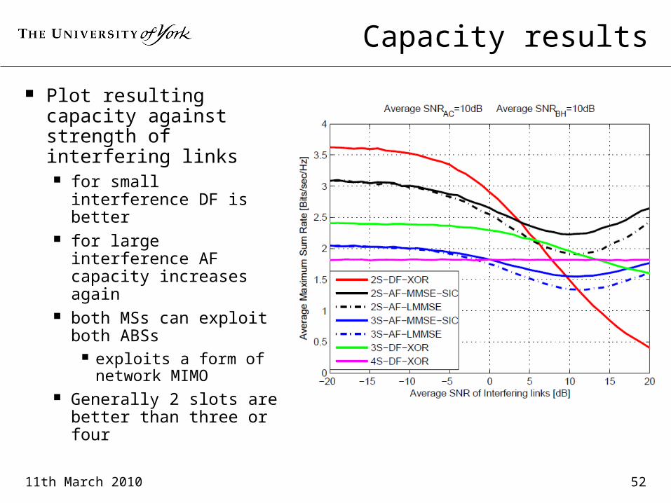
Capacity results
Plot resulting capacity against strength of interfering links for small interference
DF is better for large interference
AF capacity increases again
both MSs can exploit both ABSs
exploits a form of network MIMO
Generally 2 slots are better than three or four

11th March 2010 53
Conclusions (1)
Next generation wireless networks will be required to handle much larger capacity densities
MIMO techniques can greatly increase link capacity but still seriously affected by interference in cellular
networks Multi-user MIMO can greatly increase capacities
especially for asymmetric systems Network MIMO can further increase capacity
and also largely eliminate interference however increases backhaul load

11th March 2010 54
Conclusions (2)
Physical Layer Network Coding can better exploit backhaul capacity by allowing backhaul links to be shared by exploiting correlation of signals travelling by
different routes by overcoming duplexing constraints on spectrum
sharing All these techniques will be essential elements of
next generation networks!

11th March 2010 55
Acknowledgements
With thanks to our collaborators : Prof. Jan Sykora, Czech Technical University,
Prague Prof. Tad Matsumoto, JAIST, Japan Prof. Meixia Tao, Shanghai Jiao Tong University
and funders: European Commission, FP7 project “BuNGee” RCUK “Sciences Bridges China” programme COST 2100 programme Czech Technical University