photoelectric special sensors - murri.fi tunnistus/valokennot... · photoelectric special sensors...
TRANSCRIPT

For more information, visit us online!240
Photoelectric special sensorsfor object detection
Photoelectric Sensors
Special applications need special sensors. Our special photoelectric sensors solve very special tasks with reliability and dependability. For instance, color sensors reliably detect even the slightest color differ-ences. The first-class True Color Sensor is at home in quality control as well as sorting systems. Contrast sensors and luminescence sen-sors are perfectly suited for detection tasks, such as reading marks on packaging and sensing fill levels, determining contours, measur-ing thickness, etc.
Our broad selection of fork sensors with various widths and light types allow optimal adaptation to many detection tasks. Angle sen-sors or Dynamic optical windows are available as another alternative, in addition to light grids for packaging larger objects involving longer distances.But even if it looks like there is no space for a photoelectric sensor, Balluff provides a solution: fiber optics in glass and plastic versions.

241■ www.balluff.com
Photoelectric Special Sensors
Basic information and definitions can be found on page 884.
Photoelectric special sensors
Optical fiber base units BFB/BOS 242Plastic fiber optics BFO 256Glass fiber optics BFO 274Contrast sensors BKT 280Luminescence sensors BLT 292Color sensors BFS 302Fork sensors BGL_A 310Analog fork sensors BGL_C 330Angle sensors BWL 334Dynamic optical windows BOW 346Light grids BLG 350

242 For more information, visit us online!
Optical FiberBase Units
Fiber optics are needed whenever there is not enough space for a photoelectric sensor. Plastic fiber optics are the right choice if the requirements for tough-ness, ambient temperature or chemical resistance are not very high.There is a wide selection of special base units available with different outputs and various functions for using them: from simple models with a potentiometer to high-end devices with a display. The base units generally operate using red light.The base units for glass fiber optics find use in harsh environments thanks to their powerful infrared light. Temperatures of up to 250 °C and oil mist are not a problem thanks to the various models of glass fiber optics.
Photoelectric Special SensorsOptical fiber base units BFB/BOS
Applications
■ Small parts detection■ Suitable for tight mounting conditions■ Inspecting parts features■ Counting (e.g. counting drops)■ Precise parts positioning■ Assembly and handling technology■ Robotics

243■ www.balluff.com
Photoelectric Special SensorsOptical fiber base units BFB/BOS
Product overview
Type Light type Output Switching
type
Switch-
ing fre-
quency
US Connection Special
features
Page
Red
ligh
t
Infr
ared
ligh
t
PN
P t
rans
isto
r
NP
N t
rans
isto
r
Ana
log
outp
ut
Ala
rm o
utpu
t
Ligh
t sw
itchi
ng
Dar
k sw
itchi
ng
10
...3
0 V
DC
11
...2
6 V
DC
M8
plu
g, 3
-pin
M8
plu
g, 4
-pin
M1
2 p
lug,
4-p
in
Cab
le
Teac
h-in
Dis
play
Base units
for plastic
optical fibers
BFB0004 BFB 75K-001-P-S75 ■ ■ ■ ■ 1.5 kHz ■ ■ ■ 245
BFB0002 BFB 75K-001-N-S75 ■ ■ ■ ■ 1.5 kHz ■ ■ ■ 245
BFB0003 BFB 75K-001-P-02 ■ ■ ■ ■ 1.5 kHz ■ ■ ■ 245
BFB0001 BFB 75K-001-N-02 ■ ■ ■ ■ 1.5 kHz ■ ■ ■ 245
BFB0006 BFB 75K-002-P-S75 ■ ■ ■ ■ 8 kHz ■ ■ ■ ■ 247
BFB0005 BFB 75K-002-N-S75 ■ ■ ■ ■ 8 kHz ■ ■ ■ ■ 247
BFB0008 BFB 75K-003-P-02 ■ ■ ■ ■ ■ 8 kHz ■ ■ ■ ■ 247
BFB0007 BFB 75K-003-N-02 ■ ■ ■ ■ ■ 8 kHz ■ ■ ■ ■ 247
BOS003K BOS 73K-PU-1FR-C-02 ■ ■ ■ ■ ■ 1 kHz ■ ■ ■ ■ 249
BOS003L BOS 73K-PU-1FR-C-S75-00,1 ■ ■ ■ ■ ■ 1 kHz ■ ■ ■ ■ 249
BOS014L BOS 73K-PU-1FR-C-S49-00,3 ■ ■ ■ ■ 1 kHz ■ ■ ■ ■ 249
BOS009R BOS 6K-PU-1FR-S75-C ■ ■ ■ ■ 1 kHz ■ ■ ■ 251
BOS009P BOS 6K-PU-1FR-C-02 ■ ■ ■ ■ 1 kHz ■ ■ ■ 251
BOS008W BOS 6K-NU-1FR-S75-C ■ ■ ■ ■ 1 kHz ■ ■ ■ 251
BOS008U BOS 6K-NU-1FR-C-02 ■ ■ ■ ■ 1 kHz ■ ■ ■ 251
BOS00JJ BOS 18KF-PA-1FR-S4-C ■ ■ ■ ■ 1 kHz ■ ■ 253
BOS00JH BOS 18KF-PA-1FR-C-02 ■ ■ ■ ■ 1 kHz ■ ■ 253
BOS00HL BOS 18KF-NA-1FR-S4-C ■ ■ ■ ■ 1 kHz ■ ■ 253
BOS00HK BOS 18KF-NA-1FR-C-02 ■ ■ ■ ■ 1 kHz ■ ■ 253
Base units for
glass optical fibers
BOS0049 BOS 18M-PA-1PD-E5-C-S4 ■ ■ ■ ■ 100 Hz ■ ■ 254
BOS0080 BOS 18M-PU-1PD-SA5-C ■ ■ ■ ■ 1 kHz ■ ■ 254
BOS001P BOS 18M-PA-1PF-E5-C-S4 ■ ■ ■ ■ 200 Hz ■ ■ 255
BOS007U BOS 18M-GU-1PF-S4-Y ■ ■ ■ ■ ■ 1 kHz ■ ■ 255
BOS0134 BOS 30M-GA-1PH-S4-C ■ ■ ■ ■ ■ 100 Hz ■ ■ 255
■ Ordering code
■ Part number
Photoelectric sensors
Photoelectric standard sensors
Photoelectric special sensors
Optical fiber base units
Fiber optics
Contrast sensor
Luminescence sensor
Color sensors
Fork sensors
Angle sensors
Dynamic optical windows
Light grids
Photoelectric distance sensors for analog distance measurement
Special accessories for photoelectric sensors

For more information, visit us online!244
Photoelectric Special SensorsOptical fiber base units BFB 75K
Mounting notes for fiber optics
The resistance of the sealing ring must be overcome when connect-ing the fiber optics to the base unit.
Wiring diagrams
Operating panel
Power-on indicator
The BFB 75K-001… is ideal for any kind of standard application. This affordable sensor is installed on DIN rails and makes a great entry-level model. Ease of setting using a teach-in procedure on the sensor or via an external teach line make the sensor especially user-friendly.
Features
■ Red light■ Teach-in■ Connector and cable versions
Switching state indicator
Teach- button
Base Units for Plastic Optical Fibers
BFB 75K-001-P
BFB 75K-001-N
Ext. teach-in
Ext. teach-in
Ext. teach-in
Ext. teach-in
Suitable connector
(please order separately)
More electrical accessories: You can find a large selection of plug con-nectors and connector cables in a wide variety of cable materials, colors and lengths in our Industrial Networking and Connectivity catalog.
Size Design Cable
material
Color Length Ordering
code
M8, 4-pin Straight PUR Black 2 m BCC02N2
M8, 4-pin Straight PVC Gray 2 m BCC02PL
M8, 4-pin Angled PUR Black 2 m BCC02NC
M8, 4-pin Angled PVC Gray 2 m BCC02PZ
Connectors without LED are suitable for PNP and NPN sensors.
Color Length OrderingSuitable fiber optics can be found on page 406
Recommended accessories
(please order separately)

245■ www.balluff.com
Series BFB 75K BFB 75K
Plastic fiber optic base unit for plastic fiber optics
with an outside diameter of 2.2 mm
for plastic fiber optics
with an outside diameter of 2.2 mm
PNP NC/NO Ordering code BFB0004 BFB0003
Part number BFB 75K-001-P-S75 BFB 75K-001-P-02NPN NC/NO Ordering code BFB0002 BFB0001
Part number BFB 75K-001-N-S75 BFB 75K-001-N-02Supply voltage UB 10...30 V DC 10...30 V DCOutput current 100 mA 100 mANo-load supply current I0 max. ≤ 20 mA ≤ 20 mASwitching type Light/dark switching (selectable) Light/dark switching (selectable)Polarity reversal/short-circuit protected Yes/Yes Yes/YesSettings Teach-in Teach-inEmitter, light type LED, red light LED, red lightWavelength 660 nm 660 nmLight spot diameter Depends on the fiber optics Depends on the fiber opticsPower-on indicator Green LED Green LEDSwitching state indicator Yellow LED Yellow LEDSwitching frequency f 1.5 kHz 1.5 kHzDegree of protection as per IEC 60529 IP 64 IP 64Ambient temperature Ta –20...+60 °C –20...+60 °CPermissible ambient light per EN 60947-5-2 EN 60947-5-2Material Housing ABS ABS
Optical surface Depends on fiber optics Depends on fiber opticsConnection M8 connector, 4-pin 2 m PVC cable, 4×0.14 mm²
Connector orientation
Photoelectric Special SensorsOptical fiber base units BFB 75K
84.1
LED
Buttons
LED
Buttons
Photoelectric sensors
Photoelectric standard sensors
Photoelectric special sensors
Optical fiber base units
Fiber optics
Contrast sensor
Luminescence sensor
Color sensors
Fork sensors
Angle sensors
Dynamic optical windows
Light grids
Photoelectric distance sensors for analog distance measurement
Special accessories for photoelectric sensors

246 For more information, visit us online!
Photoelectric Special SensorsOptical fiber base units BFB 75K
Wiring diagrams
Operating panel
The BFB 75K-002…
The high-end amplifier offers perfect performance with 12-bit resolu-tion, a 4-digit display and a switching frequency up to 8 kHz.Various operating modes such as Fine or High Distance allow the sensor to be better adapted to the respective application.Several sensors can be installed next to each other. Up to four sensors installed adjacent to each other are synchronized to avoid mutual interference in an application. They are synchronized auto-matically after the supply voltage is turned on.Adjustable time functions, window programming and fine-tuning for the switching point expand its range of application options.
An additional analog output makes the BFB 75K-003... version a great all-rounder. The output signal is in proportion to the remission or to the distance of the target object. All of the functions of the BFB 75K-02 variant are included.
Green LED Power-on indicator
Red CONF LED Configuration is active Red LOCK LED Keypad lock is active Red NC LED Change switching output NO/NC Red ADJ LED Adjust function is selected Red DELAY LED Time function is selected Red FUNC LED Function is selected
Display The display represents the reflected energy in the form of a numerical value (0-4095).
Teach- buttons Configuring various functions
Yellow LEDSwitching state indicator
BFB 75K-003-P
BFB 75K-003-N
BFB 75K-002-P
BFB 75K-002-N
Suitable connector
(please order separately)
More electrical accessories: You can find a large selection of plug con-nectors and connector cables in a wide variety of cable materials, colors and lengths in our Industrial Networking and Connectivity catalog.
Operating mode Standard Highresolution
High switching frequency
High Range
Sensing distance* 150 mm 70 mm 70 mm 300 mmSwitching frequency 1 kHz 125 Hz 8 kHz 125 Hz*Depending on fiber optics used
Size Design Cable
material
Color Length Ordering
code
M8, 4-pin Straight PUR Black 2 m BCC02N2
M8, 4-pin Straight PVC Gray 2 m BCC02PL
M8, 4-pin Angled PUR Black 2 m BCC02NC
M8, 4-pin Angled PVC Gray 2 m BCC02PZ
Connectors without LED are suitable for PNP and NPN sensors.
Color Length Ordering
Ext. teach-in
Ext. teach-in
Ext. teach-in
Ext. teach-in
Mounting notes for fiber optics
The resistance of the sealing ring must be overcome when connect-ing the fiber optics to the base unit.
Suitable fiber optics can be found on page 406
Recommended accessories
(please order separately)
Features
■ Display■ 4 operating modes■ No mutual interference■ Variant with analog output
Base Units for Plastic Optical Fibers

247■ www.balluff.com
Series BFB 75K BFB 75K
Plastic fiber optic base unit for plastic fiber optics
with an outside diameter of 2.2 mm
for plastic fiber optics
with an outside diameter of 2.2 mm
PNP NC/NO Ordering code BFB0006 BFB0008
Part number BFB 75K-002-P-S75 BFB 75K-003-P-02NPN NC/NO Ordering code BFB0005 BFB0007
Part number BFB 75K-002-N-S75 BFB 75K-003-N-02Supply voltage UB 10...30 V DC 10...30 V DCOutput current 100 mA 100 mANo-load supply current I0 max. ≤ 25 mA ≤ 20 mAAnalog output 0...10 V (max. 2 mA)Switching type Light/dark switching (selectable) Light/dark switching (selectable)Polarity reversal/short-circuit protected Yes/Yes Yes/YesSettings Teach-in Teach-inEmitter, light type LED, red light LED, red lightWavelength 630 nm 630 nmLight spot diameter Depends on the fiber optics Depends on the fiber opticsPower-on indicator Green LED Green LEDSwitching state indicator Yellow LED Yellow LEDStatus indicator 6× red LEDs 6× red LEDsDisplay 4-digit 4-digitSwitching frequency f Standard 1.5 kHz 1.5 kHz
Fast Mode 8 kHz 8 kHzTime function Adjustable 1...2000 ms delay for
switching on and/or offAdjustable 1...2000 ms delay for switching on and/or off
Degree of protection as per IEC 60529 IP 64 IP 64Ambient temperature Ta –20...+60 °C –20...+60 °CPermissible ambient light per EN 60947-5-2 EN 60947-5-2Material Housing ABS ABS
Optical surface Depends on fiber optics Depends on fiber opticsConnection M8 connector, 4-pin 2 m PVC cable, 5×0.14 mm²
Photoelectric Special SensorsOptical fiber base units BFB 75K
LED
Buttons
Display
84.1
LED
Buttons
Display
Photoelectric sensors
Photoelectric standard sensors
Photoelectric special sensors
Optical fiber base units
Fiber optics
Contrast sensor
Luminescence sensor
Color sensors
Fork sensors
Angle sensors
Dynamic optical windows
Light grids
Photoelectric distance sensors for analog distance measurement
Special accessories for photoelectric sensors

248 For more information, visit us online!
SeriesPlastic fiber optic base unit
PNP NC/NO Ordering code
Part numberSupply voltage UB
Switching frequency f
Switching outputAlarm output
No-load supply current I0 max.Switching typePolarity reversal/short-circuit protectedSettingsEmitter, light typeWavelengthLight spot diameterOutput function indicatorStability indicatorDisplayResponse time
Switching frequency f
Standard
Time function
Degree of protection as per IEC 60529Ambient temperature Ta
Permissible ambient light
Material HousingOptical surface
Connection
Mounting materials included!
Photoelectric Special SensorsOptical fiber base units BOS 73K
The BOS 73K with display simplifies sensor handling and provides a precise overview of its settings.The display shows sensitivity, signal strength as well as additional functions. The switching point and hysteresis can be acquired automatically or set manually. The powerful red light emitter permits very long sens-ing distances and ranges.A switching and alarm output is also provided as an output and time functions can also be set.Multiple sensors can be used without them interfering with each other thanks to two transmission channels.
Features
■ LCD display with backlighting■ Settings via teach-in■ Powerful red light emitter for long ranges■ Contamination output■ All time functions can be set from 10...120 ms■ Two transmission channels
Wiring diagrams
PNPAlarmExt. teach-in
AlarmPNP
+
PNP
BOS 73K...-02
BOS 73K...-S75
BOS 73K...-S49
Suitable connector
(please order separately)
More electrical accessories: You can find a large selection of plug con-nectors and connector cables in a wide variety of cable materials, colors and lengths in our Industrial Networking and Connectivity catalog.
Size Design Cable
material
Color Length Ordering
code
M8, 4-pin Straight PUR Black 2 m BCC02N2
M8, 4-pin Straight PVC Gray 2 m BCC02PL
M8, 4-pin Angled PUR Black 2 m BCC02NC
M8, 4-pin Angled PVC Gray 2 m BCC02PZ
Connectors without LED are suitable for PNP and NPN sensors.
Color Length Ordering
Operating panelClamp lever Stability indicator Teach-in Function selection
Operating modeOutput function indicator Display
Mode L: Light switching D: Dark switching O: On-delay F: Off-delay
Display
Sensitivity range 8-level display (1, 2...8)
Amount of received light
Transmission frequency channel
Functions Sensor functions Additional functions A: Automatic S: Manual sensitivity setting/switch-on point Detection H: Manual hysteresis setting (switch-off point) T: Teach-in V: Signal strength fluctuation and absolute value display L: Lock
Suitable connector
(please order separately)
More electrical accessories: You can find a large selection of plug con-nectors and connector cables in a wide variety of cable materials, colors and lengths in our Industrial Networking and Connectivity catalog.
Size Design Cable
material
Color Length Ordering
code
M8, 3-pin Straight PUR Black 2 m BCC02M8
M8, 3-pin Straight PVC Gray 2 m BCC02NU
M8, 3-pin Angled PUR Black 2 m BCC02ML
M8, 3-pin Angled PVC Gray 2 m BCC02P5
Connectors without LED are suitable for PNP and NPN sensors.
Base Units for Plastic Optical Fibers

249■ www.balluff.com
BOS 73K BOS 73K BOS 73K
for plastic fiber optics
with an outside diameter of 2.2 mm
for plastic fiber optics
with an outside diameter of 2.2 mm
for plastic fiber optics
with an outside diameter of 2.2 mm
BOS003K BOS003L BOS014L
BOS 73K-PU-1FR-C-02 BOS 73K-PU-1FR-C-S75-00,1 BOS 73K-PU-1FR-C-S49-00,311...26 V DC 11...26 V DC 11...26 V DC100 mA 100 mA 100 mA50 mA 50 mA≤ 50 mA ≤ 50 mA ≤ 50 mALight/dark switching (selectable) Light/dark switching (selectable) Light/dark switching (selectable)Yes/Yes Yes/Yes Yes/YesTeach-in/Manually using buttons Teach-in/Manually using buttons Teach-in/Manually using buttonsLED, red light LED, red light LED, red light660 nm 660 nm 660 nmDepends on the fiber optics Depends on the fiber optics Depends on the fiber opticsOrange LED Orange LED Orange LEDGreen LED Green LED Green LEDBacklit LCD Backlit LCD Backlit LCDChannel 1: 0.5 ms Channel 1: 0.5 ms Channel 1: 0.5 msChannel 2: 0.6 ms Channel 2: 0.6 ms Channel 2: 0.6 msChannel 1: 1kHz Channel 1: 1kHz Channel 1: 1kHzChannel 2: 833 kHz Channel 2: 833 kHz Channel 2: 833 kHzOn/off delay 10…120 ms selectable
On/off delay 10…120 ms selectable
On/off delay 10…120 ms selectable
IP 54 IP 54 IP 54–25...+55 °C –25...+55 °C –25...+55 °CArtificial light ≤ 10 klx, Sunlight ≤ 20 klx
Artificial light ≤ 10 klx, Sunlight ≤ 20 klx
Artificial light ≤ 10 klx, Sunlight ≤ 20 klx
ABS ABS ABSDepends on fiber optics Depends on fiber optics Depends on fiber optics2 m PVC cable, 5×0.2 mm² Pigtail 10 cm,
M8 connector, 4-pinPigtail 30 cm,M8 connector, 3-pin
Photoelectric Special SensorsOptical fiber base units BOS 73K
68
Suitable fiber optics can be found on page 406
Recommended accessories
(please order separately)
Photoelectric sensors
Photoelectric standard sensors
Photoelectric special sensors
Optical fiber base units
Fiber optics
Contrast sensor
Luminescence sensor
Color sensors
Fork sensors
Angle sensors
Dynamic optical windows
Light grids
Photoelectric distance sensors for analog distance measurement
Special accessories for photoelectric sensors

250 For more information, visit us online!
Photoelectric Special SensorsOptical fiber base units BOS 6K
The BOS 6K series also offers a optical fiber base unit that is easy to teach in externally using a button or control line. Together with the BFO series of fiber optics, an enclosure rating of IP 67 is provided.
Features
■ Teach-in■ Contamination indicator■ Control line for external teach-in■ Disable buttons
Wiring diagrams
BOS 6K-PU-...
BOS 6K-NU-...
Ext. teach-in
Ext. teach-in
Ext. teach-in
Ext. teach-in
More mechanical accessories: You can find a large selection of mounting components of all types, such as clamping holders, mounting brackets and the Balluff mounting system BMS, in our Accessory Product Line catalog.
Description Ordering
code
Mounting bracket BAM00UH
Suitable connector
(please order separately)
More electrical accessories: You can find a large selection of plug con-nectors and connector cables in a wide variety of cable materials, colors and lengths in our Industrial Networking and Connectivity catalog.
Size Design Cable
material
Color Length Ordering
code
M8, 4-pin Straight PUR Black 2 m BCC02N2
M8, 4-pin Straight PVC Gray 2 m BCC02PL
M8, 4-pin Angled PUR Black 2 m BCC02NC
M8, 4-pin Angled PVC Gray 2 m BCC02PZ
Connectors without LED are suitable for PNP and NPN sensors.
Color Length Ordering
Suitable fiber optics can be found on page 406
Base Units for Plastic Optical Fibers
Recommended accessories
(please order separately)

251■ www.balluff.com
Series BOS 6K BOS 6K
Plastic fiber optic base unit for plastic fiber optics
with an outside diameter of 2.2 mm
for plastic fiber optics
with an outside diameter of 2.2 mm
PNP NC/NO Ordering code BOS009R BOS009P
Part number BOS 6K-PU-1FR-S75-C BOS 6K-PU-1FR-C-02NPN NC/NO Ordering code BOS008W BOS008U
Part number BOS 6K-NU-1FR-S75-C BOS 6K-NU-1FR-C-02Supply voltage UB 10...30 V DC 10...30 V DCOutput current 100 mA 100 mANo-load supply current I0 max. ≤ 25 mA ≤ 25 mASwitching type Light/dark switching (selectable) Light/dark switching (selectable)Polarity reversal/short-circuit protected Yes/Yes Yes/YesSettings Teach-in Teach-inEmitter, light type LED, red light LED, red lightWavelength 660 nm 660 nmLight spot diameter Depends on range/sensing distance Depends on range/sensing distanceOutput function indicator Yellow LED Yellow LEDStability indicator Green LED Green LEDResponse time 0.5 ms 0.5 msSwitching frequency f 1 kHz 1 kHzNo. of wires × conductor cross-section 4×0.14 mm²Degree of protection as per IEC 60529 IP 67 IP 67Ambient temperature Ta –20...+60 °C –20...+60 °CPermissible ambient light EN 60947-5-2 EN 60947-5-2Material Housing ABS ABS
Optical surface Depends on fiber optics Depends on fiber opticsConnection M8 connector, 4-pin 2 m PVC cable
Connector orientation
Photoelectric Special SensorsOptical fiber base units BOS 6K
Photoelectric sensors
Photoelectric standard sensors
Photoelectric special sensors
Optical fiber base units
Fiber optics
Contrast sensor
Luminescence sensor
Color sensors
Fork sensors
Angle sensors
Dynamic optical windows
Light grids
Photoelectric distance sensors for analog distance measurement
Special accessories for photoelectric sensors

252 For more information, visit us online!
Photoelectric Special SensorsOptical fiber base units BOS 18KF
The optical fiber base unit BOS 18KF is a highlight far away from DIN rail installation, distinguishing itself with simple operation and installation.
Features
■ Sensitivity setting using 270°- potentiometer■ Cap nut for adapting optical fibers
Connector orientation Wiring diagrams
BN
BK
WH
BU
+UB
0 V
BN
BK
WH
BU
+UB
0 V
BOS 18KF-PA-...
BOS 18KF-NA-...
Suitable connector
(please order separately)
More electrical accessories: You can find a large selection of plug con-nectors and connector cables in a wide variety of cable materials, colors and lengths in our Industrial Networking and Connectivity catalog.
Size Design Cable
material
Color Length Ordering
code
M12, 4-pin Straight PUR Black 2 m BCC032F
M12, 4-pin Straight PVC Gray 2 m BCC0367
M12, 4-pin Angled PUR Black 2 m BCC032Y
M12, 4-pin Angled PVC Gray 2 m BCC036N
Connectors without LED are suitable for PNP and NPN sensors.
Recommended accessories
(please order separately)
More mechanical accessories: You can find a large selection of mounting components of all types, such as clamping holders, mounting brackets and the Balluff mounting system BMS, in our Accessory Product Line catalog.
Description Ordering
code
1 Mounting bracket BAM00RY
2 Mounting clamp BAM00T3
Suitable fiber optics can be found on page 406
12
Base Units for Plastic Optical Fibers

253■ www.balluff.com
Series BOS 18KF BOS 18KF
Plastic fiber optic base unit for plastic fiber optics
with an outside diameter of 2.2 mm
for plastic fiber optics
with an outside diameter of 2.2 mm
PNP NC/NO Ordering code BOS00JJ BOS00JH
Part number BOS 18KF-PA-1FR-S4-C BOS 18KF-PA-1FR-C-02NPN NC/NO Ordering code BOS00HL BOS00HK
Part number BOS 18KF-NA-1FR-S4-C BOS 18KF-NA-1FR-C-02Supply voltage UB 10...30 V DC 10...30 V DCNo-load supply current I0 max. ≤ 35 mA ≤ 35 mAOutput current 100 mA 100 mASwitching type Light and dark switching Light and dark switchingPolarity reversal/short-circuit protected Yes/Yes Yes/YesSettings Potentiometer, 270° Potentiometer, 270°Emitter, light type LED, red light LED, red lightWavelength 660 nm 660 nmLight spot diameter Depends on range/sensing distance Depends on range/sensing distanceOutput function indicator Yellow LED Yellow LEDStability indicator Green LED Green LEDResponse time 0.5 ms 0.5 msSwitching frequency f 1 kHz 1 kHzDegree of protection as per IEC 60529 IP 67 IP 67Ambient temperature Ta –25...+55 °C –25...+55 °CPermissible ambient light EN 60947-5-2 EN 60947-5-2Material Housing PBT PBT
Optical surface Depends on fiber optics Depends on fiber opticsConnection M12 connector, 4-pin 2 m PVC cable, 4×0.14 mm²
Photoelectric Special SensorsOptical fiber base units BOS 18KF
Photoelectric sensors
Photoelectric standard sensors
Photoelectric special sensors
Optical fiber base units
Fiber optics
Contrast sensor
Luminescence sensor
Color sensors
Fork sensors
Angle sensors
Dynamic optical windows
Light grids
Photoelectric distance sensors for analog distance measurement
Special accessories for photoelectric sensors

254 For more information, visit us online!
Photoelectric Special SensorsOptical fiber base units BOS
Type Diffuse sensor, energetic Diffuse sensor, energetic
Detection range 0...400 mm 0...400 mm
PNP NC/NO Ordering code BOS0049 BOS0080
Part number BOS 18M-PA-1PD-E5-C-S4 BOS 18M-PU-1PD-SA5-CPNP/NPN NC/NO Ordering code
Part numberSupply voltage UB 10...30 V DC 10...30 V DCOutput current 200 mA 200 mANo-load supply current I0 max. ≤ 20 mA ≤ 25 mASwitching type Light/dark switching (complementary) Light/dark switching (selectable)Polarity reversal/short-circuit protected Yes/Yes Yes/YesSettings Potentiometer, 270˚ 18-turn potentiometerEmitter, light type LED, infrared LED, infraredWavelength 880 nm 880 nmResponse time 5 ms 5 msSwitching frequency f 100 Hz 1 kHzDegree of protection as per IEC 60529 IP 67 IP 67Ambient temperature Ta –5...+55 °C –20...+60 °CPermissible ambient light 5 klx 2 klxMaterial Housing Nickel-plated CuZn Nickel-plated CuZn
Optical surface PMMA GlassConnection M12 connector, 4-pin M12 connector, 4-pin
Base Units for Glass Optical Fibers
Suitable connector
(please order separately)
More electrical accessories: You can find a large selection of plug con-nectors and connector cables in a wide variety of cable materials, colors and lengths in our Industrial Networking and Connectivity catalog.
Size Design Cable
material
Color Length Ordering
code
M12, 4-pin Straight PUR Black 2 m BCC032F
M12, 4-pin Straight PVC Gray 2 m BCC0367
M12, 4-pin Angled PUR Black 2 m BCC032Y
M12, 4-pin Angled PVC Gray 2 m BCC036N
Connectors without LED are suitable for PNP and NPN sensors.
Recommended accessories
(please order separately)
You can find special accessories for diffuse sensors, such as reflectors, apertures, lenses, filters and deflection heads, in this catalog starting on page 379.
More mechanical accessories: You can find a large selection of mounting components of all types, such as clamping holders, mounting brackets and the Balluff mounting system BMS, in our Accessory Product Line catalog.
Description Ordering
code
Mounting clamp BAM00T3
y)

255■ www.balluff.com
Photoelectric Special SensorsOptical fiber base units BOS
Diffuse sensor Diffuse sensor Diffuse sensor
0...1 m 0...1 m 0...2 m
BOS001P
BOS 18M-PA-1PF-E5-C-S4BOS007U BOS0134
BOS 18M-GU-1PF-S4-Y BOS 30M-GA-1PH-S4-C10...30 V DC 11...30 V DC 10...30 V DC200 mA 200 mA 200 mA≤ 20 mA ≤ 25 mA ≤ 40 mALight/dark switching (complementary) Light/dark switching (selectable) Light/dark switching (complementary)Yes/Yes Yes/Yes Yes/YesPotentiometer, 270˚ 18-turn potentiometer 18-turn potentiometerLED, infrared LED, infrared LED, infrared880 nm 880 nm 880 nm2.5 ms 0.5 ms 5 ms200 Hz 1 kHz 100 HzIP 67 IP 65 IP 65–5...+55 °C –20...+60 °C –20...+60 °C5 klx 1 klx 1 klxNickel-plated CuZn Nickel-plated CuZn Nickel-plated CuZnPMMA Glass GlassM12 connector, 4-pin M12 connector, 4-pin M12 connector, 4-pin
56
Wiring diagrams
BOS 18M-PA-...
BOS 18M-PU-...
BOS 30M-GA-1PH-S4-C-...
BOS 18M-GU-...
Photoelectric sensors
Photoelectric standard sensors
Photoelectric special sensors
Optical fiber base units
Fiber optics
Contrast sensor
Luminescence sensor
Color sensors
Fork sensors
Angle sensors
Dynamic optical windows
Light grids
Photoelectric distance sensors for analog distance measurement
Special accessories for photoelectric sensors

256 For more information, visit us online!
PlasticFiber Optics
Fiber optics are generally available in a diffuse sensor or through-beam design.The diffuse sensors have an integrated emitter and receiver fiber at the optical head; the through-beam sensors use two separate opti-cal fibers. It is easy to see why optical fibers are so commonly used: The variety of end configurations, with straight or angled light exit, flexible optical head or coaxial fiber arrangement, the various fiber diameters and the ability to trim them to the desired length.
Another plus
For complete flexibility, there are also fiber optics for user assembly; the length of the duplex cable can be trimmed as needed and can be combined with various end fittings as desired.
Applications
■ Small parts detection■ For tight mounting conditions■ Inspecting parts features■ Counting (e.g. counting drops) ■ Precise parts positioning■ Handling and assembly technology■ Robotics
Photoelectric Special SensorsPlastic fiber optics BFO

257■ www.balluff.com
Photoelectric Special SensorsBFO plastic fiber optics
Product overview
Type Optical
head
Light exit Fiber
arrangement
Core diameter Features Page
Str
aigh
t
90
°
Sta
ndar
d
Coa
xial
Ligh
t gr
id
1.5
mm
1.0
mm
0.5
mm
0.2
5 m
m
Ben
dabl
e op
tical
tip
Exte
nded
tem
pera
ture
ran
ge
Hig
hly
flexi
ble
Through-beam fiber optics
BFO005M BFO D22-LA-KB-EAK-10-02 M4 ■ ■ ■ 258
BFO005T BFO D22-LAH-KB-EAK-10-02 M4 ■ ■ ■ ■ 258
BFO005W BFO D22-LAT-KB-EAK-10-02 M4 ■ ■ ■ ■ 258
BFO005U BFO D22-LAP-KB-EAK-15-02 M4 ■ ■ ■ 259
BFO0002 BFO D22-LA-TB-EAK-10-02 M4 ■ ■ ■ ■ 259
BFO005N BFO D22-LA-NB-PZK-10-02 M4 ■ ■ ■ ■ 259
BFO00AW BFO D22-LAH-BK-EAK-10-02 M4 ■ ■ ■ ■ 259
BFO005R BFO D22-LA-RB-EAK-10-02 M3 ■ ■ ■ 260
BFO000C BFO N22-LA-FB-EAK-05-01 M2 ■ ■ ■ 260
BFO00AY BFO D22-LAT-YB-EAK-10-0,5 Ø3 ■ ■ ■ ■ 260
BFO005P BFO D22-LA-QB-PAK-05-02 Ø3 ■ ■ ■ 261
BFO0056 BFO D13-LA-QB-EAK-05-02 Ø3 ■ ■ ■ 261
BFO0051 BFO D10-LA-CB-EAK-05-02 Ø2 ■ ■ ■ 261
BFO0057 BFO D13-LA-WB-EAK-05-02 Ø2 ■ ■ ■ 261
BFO00AP BFO D22-LA-GD-EAK-52-02 10×10 ■ ■ ■ 262
BFO005H BFO D22-LA-AD-EAK-52-02 20×10 ■ ■ ■ 262
BFO005K BFO D22-LA-BD-EAK-52-02 15×15 ■ ■ ■ 262
BFO0067 BFO D25-LA-CD-EAK-110-02 19×25 ■ ■ ■ 263
BFO00C5 BFO D25-LA-ED-EAK-250-0,5 19×38 ■ ■ ■ 263
BFO0068 BFO D25-LA-ED-EAK-250-02 19×38 ■ ■ ■ 263
BFB00C8 BFO D25 LA-HD-EAK-465-02 23×55 ■ ■ ■ 263
BFO0058 BFO D13-LG-05-EAK-30-02 15×41 ■ ■ 264
BFO0059 BFO D13-LG-10-EAK-30-02 20×32 ■ ■ 264
BFO000E BFO D22-LAH-ZB-EAK-10-02 5×4 ■ ■ ■ ■ 264
BFO00C6 BFO D10-LAH-CK-EAK-05-02 11×6 ■ ■ ■ ■ 265
BFO00C7 BFO D10-LAH-DK-EAK-05-02 13×7 ■ ■ ■ ■ 265
Diffuse sensor fiber optics
BFO0061 BFO D22-XA-LB-EAK-20-02 M6 ■ ■ ■ 266
BFO0063 BFO D22-XAH-LB-EAK-20-02 M6 ■ ■ ■ ■ 266
BFO0065 BFO D22-XAT-LB-EAK-20-02 M6 ■ ■ ■ ■ 266
BFO0064 BFO D22-XAP-LB-EAK-30-02 M6 ■ ■ ■ 267
BFO0066 BFO D22-XB-LB-EAK-15-02 M6 ■ ■ ■ 267
BFO0007 BFO D22-XBF-LB-EAK-15-02 M6 ■ ■ ■ ■ 267
BFO0004 BFO D22-XA-SB-EAK-20-02 M6 ■ ■ ■ ■ 267
BFO0005 BFO D22-XA-UB-EAK-20-02 M4 ■ ■ ■ 268
BFO0006 BFO D22-XB-UB-EAK-15-02 M4 ■ ■ ■ 268
BFO0055 BFO D10-XAH-KB-EAK-10-02 M4 ■ ■ ■ ■ 268
BFO005C BFO D13-XB-KB-EAK-10-02 M4 ■ ■ ■ 269
BFO0053 BFO D10-XA-HB-EAK-10-02 M4 ■ ■ ■ ■ 269
BFO0054 BFO D10-XA-RB-EAK-10-02 M3 ■ ■ ■ 269
BFO005E BFO D13-XB-RB-EAK-10-02 M3 ■ ■ ■ 269
BFO00C3 BFO D10-XA-VB-EAK-10-02 M3 ■ ■ ■ ■ 269
BFO0052 BFO D10-XA-GB-EAK-10-02 M3 ■ ■ ■ ■ 270
BFO005A BFO D13-XA-JB-EAK-20-02 Ø3 ■ ■ ■ 270
BFO0062 BFO D22-XA-MB-PAK-10-02 Ø3 ■ ■ ■ 270
BFO00AT BFO D13-XB-AB-EAK-10-01 Ø2.5 ■ ■ ■ 271
BFO00AR BFO D13-XV-AK-EAK-50-02 13×20 ■ ■ 271
BFO005Z BFO D22-XA-CD-EAK-110-02 19×25 ■ ■ ■ 271
BFO0060 BFO D22-XA-ED-EAK-250-02 19×38 ■ ■ ■ 271
■ Ordering code
■ Part number
Photoelectric sensors
Photoelectric standard sensors
Photoelectric special sensors
Optical fiber base units
Fiber optics
Contrast sensor
Luminescence sensor
Color sensors
Fork sensors
Angle sensors
Dynamic optical windows
Light grids
Photoelectric distance sensors for analog distance measurement
Special accessories for photoelectric sensors

For more information, visit us online!258
Optical head M4 thread M4 thread M4 thread
Features Standard Highly flexible Temperature rated
Straight light exit Ordering code BFO005M BFO005T BFO005W
Part number BFO D22-LA-KB-EAK-10-02 BFO D22-LAH-KB-EAK-10-02 BFO D22-LAT-KB-EAK-10-0290° light exit Ordering code
Part numberSheathing Ø 2.2 mm 2.2 mm 2.2 mmCore Ø 1 mm 1 mm 1 mmFiber length 2 m 2 m 2 mFiber bending radius ≥ 25 mm ≥ 2 mm ≥ 25 mmHead bending radiusTemperature range –55...+70 °C –40...+70 °C –55...+105 °CRange with BFB 75K-001 500 mm 300 mm 600 mm
with BFB 75K-002* 500 mm 300 mm 600 mmwith BFB 73K 500 mm 300 mm 500 mmwith BFB 6K 220 mm 200 mm 230 mmwith BFB 18KF 120 mm 90 mm 120 mm
Packaging unit: 2
*Max. range in standard mode
Photoelectric Special SensorsBFO plastic fiber optics
Through-beam
Ø3.5 Ø3.5 Ø3.5
PlasticFiber Optics

259■ www.balluff.com
M4 thread M4 thread M4 thread M4 thread
Long range Bendable optical tip Bendable optical tip Highly flexible
BFO005U BFO0002 BFO005N
BFO D22-LAP-KB-EAK-15-02 BFO D22-LA-TB-EAK-10-02 BFO D22-LA-NB-PZK-10-02BFO00AW
BFO D22-LAH-BK-EAK-10-022.2 mm 2.2 mm 2.2 mm 2.2 mm1.5 mm 1 mm 1 mm 1 mm2 m 2 m 2 m 2 m≥ 40 mm ≥ 25 mm ≥ 25 mm ≥ 2 mm
≥ 10 mm ≥ 10 mm–55...+70 °C –30...+60 °C –55...+70 °C –40...+70 °C800 mm 450 mm 500 mm 250 mm800 mm 450 mm 500 mm 250 mm800 mm 400 mm 500 mm 250 mm 500 mm 200 mm 250 mm 170 mm250 mm 110 mm 120 mm 80 mm
Photoelectric Special SensorsPlastic fiber optics BFO
Through-beam
Ø1.5
4Ø3
Ø2.6
11
34.17
7.3
8.1
M4
M2.6
Photo- electric sensors
Photo- electric standard sensors
Photo- electric special sensors
Optical fiber base units
Fiber optics
Contrast sensor
Luminescence sensor
Color sensors
Fork sensors
Angle sensors
Dynamic optical windows
Light grids
Photo- electric distance sensors for analog distance measurement
Special accessories for photo- electric sensors

For more information, visit us online!260
Optical head M3 thread M2 thread Ø 3
Features Standard Precision Temperature rated
Straight light exit Ordering code BFO005R BFO000C
Part number BFO D22-LA-RB-EAK-10-02 BFO N22-LA-FB-EAK-05-0190° light exit Ordering code BFO00AY
Part number BFO D22-LAT-YB-EAK-10-0,5Sheathing Ø 2.2 mm 1 mm 2.2 mmCore Ø 1 mm 0.5 mm 1 mmFiber length 2 m 2 m 0.5 mFiber bending radius ≥ 25 mm ≥ 10 mm ≥ 25 mmHead bending radiusTemperature range –55...+70 °C –30...+60 °C –55...+70 °CRange with BFB 75K-001 500 mm 140 mm 600 mm
with BFB 75K-002* 500 mm 140 mm 600 mmwith BFB 73K 450 mm 130 mm 500 mmwith BFB 6K 220 mm 50 mm 230 mmwith BFB 18KF 100 mm 20 mm 120 mm
Packaging unit: 2
*Max. range in standard mode
20
8
12
1.5
Ø2.6
1
1.5
15
5
2.9
Ø3Ø1
Photoelectric Special SensorsBFO plastic fiber optics
Through-beam
Ø2.8
PlasticFiber Optics

261■ www.balluff.com
Ø 3 Ø 3 Ø 2 Ø 2
Light exit on side Light exit on side Precision Standard
BFO0051
BFO D10-LA-CB-EAK-05-02BFO005P BFO0056 BFO0057
BFO D22-LA-QB-PAK-05-02 BFO D13-LA-QB-EAK-05-02 BFO D13-LA-WB-EAK-05-022.2 mm 1.3 mm 1 mm 1.3 mm1 mm 0.5 mm 0.5 mm 1 mm2 m 2 m 2 m 2 m≥ 25 mm ≥ 15 mm ≤ 15 m ≥ 25 mm
–40...+70 °C –35...+65 °C –55...+70 °C –40...+70 °C120 mm 110 mm 130 mm 75 mm120 mm 110 mm 130 mm 75 mm115 mm 105 mm 120 mm 70 mm65 mm − − −35 mm 25 mm − 20 mm
15
1
Ø0.6
Photoelectric Special SensorsBFO plastic fiber optics
Through-beam
Photoelectric sensors
Photoelectric standard sensors
Photoelectric special sensors
Optical fiber base units
Fiber optics
Contrast sensor
Luminescence sensor
Color sensors
Fork sensors
Angle sensors
Dynamic optical windows
Light grids
Photoelectric distance sensors for analog distance measurement
Special accessories for photoelectric sensors

For more information, visit us online!262
Optical head 10×10 mm 20×10 mm 15×15 mm
Features Light grid Light grid Light grid
Straight light exit Ordering code BFO00AP BFO005H
Part number BFO D22-LA-GD-EAK-52-02 BFO D22-LA-AD-EAK-52-0290° light exit Ordering code BFO005K
Part number BFO D22-LA-BD-EAK-52-02Sheathing Ø 2.2 mm 2.2 mm 2.2 mmCore Ø 16×0.25 mm 16×0.25 mm 16×0.25 mmFiber length 2 m 2 m 2 mFiber bending radius ≥ 25 mm ≥ 25 mm ≥ 25 mmTemperature range –55...+70 °C –35...+65 °C –55...+70 °CRange with BFB 75K-001 600 mm 450 mm 400 mm
with BFB 75K-002* 600 mm 450 mm 400 mmwith BFB 73K 600 mm 400 mm 350 mmwith BFB 6K 350 mm 220 mm 180 mmwith BFB 18KF 230 mm 130 mm 110 mm
Packaging unit: 2
*Max. range in standard mode
Photoelectric Special SensorsBFO plastic fiber optics
Through-beam
M2
2.5
102.5
3.5
1
2.5
Ø0.25(16x)
5.4
10
5
2.5
1
PlasticFiber Optics

263■ www.balluff.com
19×25 mm 19×38 mm 19×38 mm 23×55 mm
Light grid Light grid Light grid Light grid
BFO0067
BFO D25-LA-CD-EAK-110-02BFO00C5 BFO0068 BFB00C8
BFO D25-LA-ED-EAK-250-0,5 BFO D25-LA-ED-EAK-250-02 BFO D25 LA-HD-EAK-465-022.8 mm 2.8 mm 2.8 mm 2.8 mm32×0.25 mm 32×0.25 mm 32×0.25 mm 32×0.25 mm2 m 0.5 m 2 m 2 m≥ 10 mm ≥ 60 mm ≥ 60 mm ≥ 60 mm–55...+70 °C –55...+70 °C –55...+70 °C –55...+70 °C600 mm 550 mm 550 mm 550 mm600 mm 550 mm 550 mm 550 mm600 mm 550 mm 550 mm 550 mm350 mm 360 mm 360 mm 360 mm230 mm 210 mm 210 mm 210 mm
Photoelectric Special SensorsBFO plastic fiber optics
Through-beam
Photoelectric sensors
Photoelectric standard sensors
Photoelectric special sensors
Optical fiber base units
Fiber optics
Contrast sensor
Luminescence sensor
Color sensors
Fork sensors
Angle sensors
Dynamic optical windows
Light grids
Photoelectric distance sensors for analog distance measurement
Special accessories for photoelectric sensors
12
6
19
5.1
6.2
10
21
5.1
6.2
10
21
5.1
6.2
10
21

For more information, visit us online!264
Optical head 15×41 mm 20×32 mm 5×4 mm
Features Fork Fork Highly flexible
Straight light exit Ordering code
Part number90° light exit Ordering code BFO0058 BFO0059 BFO000E
Part number BFO D13-LG-05-EAK-30-02 BFO D13-LG-10-EAK-30-02 BFO D22-LAH-ZB-EAK-10-02Sheathing Ø 2×1.25 mm 2×1.25 mm 2.2 mmCore Ø 2×0.25 mm 2×0.25 mm 1 mmFiber length 2 m 2 m 2 mFiber bending radius ≥ 10 mm ≥ 10 mm ≥ 2 mmTemperature range –55...+70 °C –55...+70 °C –55...+70 °CRange with BFB 75K-001 5 mm 10 mm 300 mm
with BFB 75K-002* 5 mm 10 mm 300 mmwith BFB 73K 5 mm 10 mm 300 mmwith BFB 6K 5 mm 10 mm 200 mmwith BFB 18KF 5 mm 10 mm 90 mm
Packaging unit: 2
*Max. range in standard mode
Photoelectric Special SensorsBFO plastic fiber optics
Through-beam
5
3 2
4
2
15
5
Ø3.5
Ø2
PlasticFiber Optics

265■ www.balluff.com
11×6 mm 13×7 mm
Highly flexible Highly flexible
BFO00C6 BFO00C7
BFO D10-LAH-CK-EAK-05-02 BFO D10-LAH-DK-EAK-05-021 mm 1 mm0.5 mm 0.5 mm2 m 2 m≥ 1 mm ≥ 1 mm–40...+70 °C –40...+70 °C55 mm 50 mm55 mm 50 mm45 mm 40 mm− −20 mm 20 mm
Photoelectric Special SensorsBFO plastic fiber optics
Through-beam
Photoelectric sensors
Photoelectric standard sensors
Photoelectric special sensors
Optical fiber base units
Fiber optics
Contrast sensor
Luminescence sensor
Color sensors
Fork sensors
Angle sensors
Dynamic optical windows
Light grids
Photoelectric distance sensors for analog distance measurement
Special accessories for photoelectric sensors
Ø2.2
Ø4
25.5
15
4
4
2.5 6
10.5
Ø3.6
Ø2.1
2
7
13
8
4.5
5.5
Ø2.1
Ø3.6
25.5
15Ø2.2
Ø4

For more information, visit us online!266
Optical head M6 thread M6 thread M6 thread
Features Standard Highly flexible Temperature rated
Straight light exit Ordering code BFO0061 BFO0063 BFO0065
Part number BFO D22-XA-LB-EAK-20-02 BFO D22-XAH-LB-EAK-20-02 BFO D22-XAT-LB-EAK-20-02Sheathing Ø 2×2.2 mm 2×2.2 mm 2×2.2 mmCore Ø 2×1 mm 2×1 mm 2×1 mmFiber bending radius ≥ 25 mm ≥ 2 mm ≥ 25 mmHead bending radiusTemperature range –55...+70 °C –40...+70 °C –55...+115 °CRange with BFB 75K-001 150 mm 120 mm 130 mm
with BFB 75K-002* 150 mm 120 mm 130 mmwith BFB 73K 150 mm 120 mm 130 mmwith BFB 6K 100 mm 70 mm 90 mmwith BFB 18KF 50 mm 30 mm 50 mm
*Max. range in standard mode
Photoelectric Special SensorsBFO plastic fiber optics
Buttons
PlasticFiber Optics

267■ www.balluff.com
M6 thread M6 thread M6 thread M6 thread
Long range Coaxial Coaxial, flexible Bendable optical tip
BFO0064 BFO0066 BFO0007 BFO0004
BFO D22-XAP-LB-EAK-30-02 BFO D22-XB-LB-EAK-15-02 BFO D22-XBF-LB-EAK-15-02 BFO D22-XA-SB-EAK-20-022×2.2 mm 2×2.2 mm 2×2.2 mm 2×2.2 mm2×1.5 mm 1×1 mm/16×0.25 mm 1×1 mm/16×0.25 mm 2×1 mm≥ 40 mm ≥ 25 mm ≥ 5 mm ≥ 25 mm
≥ 15 mm–55...+70 °C –55...+70 °C –40...+60 °C –35...+65 °C180 mm 120 mm 110 mm 130 mm180 mm 120 mm 110 mm 130 mm180 mm 120 mm 120 mm 130 mm130 mm 80 mm 70 mm 90 mm100 mm 50 mm 30 mm 40 mm
Photoelectric Special SensorsBFO plastic fiber optics
Buttons
Ø4.5
18
6
113
90
23
Photoelectric sensors
Photoelectric standard sensors
Photoelectric special sensors
Optical fiber base units
Fiber optics
Contrast sensor
Luminescence sensor
Color sensors
Fork sensors
Angle sensors
Dynamic optical windows
Light grids
Photoelectric distance sensors for analog distance measurement
Special accessories for photoelectric sensors

For more information, visit us online!268
Optical head M4 thread M4 thread M4 thread
Features Standard Coaxial Highly flexible
Straight light exit Ordering code BFO0005 BFO0006 BFO0055
Part number BFO D22-XA-UB-EAK-20-02 BFO D22-XB-UB-EAK-15-02 BFO D10-XAH-KB-EAK-10-02Sheathing Ø 2×2.2 mm 2×2.2 mm 2×1 mmCore Ø 2×1 mm 1×1 mm/16×0.25 mm 2×0.5 mmFiber bending radius ≥ 25 mm ≥ 25 mm ≥ 1 mmHead bending radiusTemperature range –35...+65 °C –40...+60 °C –40...+70 °CRange with BFB 75K-001 120 mm 130 mm 40 mm
with BFB 75K-002* 120 mm 130 mm 40 mmwith BFB 73K 120 mm 130 mm 30 mmwith BFB 6K 80 mm 90 mm −with BFB 18KF 40 mm 50 mm 10 mm
*Max. range in standard mode
Photoelectric Special SensorsBFO plastic fiber optics
Buttons
21
12
Ø2.8
PlasticFiber Optics

269■ www.balluff.com
M4 thread M4 thread M3 thread M3 thread M3 thread
Coaxial Bendable optical tip Standard Coaxial Bendable optical tip
BFO005C BFO0053 BFO0054 BFO005E BFO00C3
BFO D13-XB-KB-EAK-10-02 BFO D10-XA-HB-EAK-10-02 BFO D10-XA-RB-EAK-10-02 BFO D13-XB-RB-EAK-10-02 BFO D10-XA-VB-EAK-10-022×1.25 mm 2×1 mm 2×1 mm 2×1.25 mm 2×1 mm1×0.5 mm/9×0.25 mm 2×0.5 mm 2×0.5 mm 1×0.5 mm/9×0.25 mm 2×0.5 mm≥ 15 mm ≥ 15 mm ≥ 15 mm ≥ 15 mm ≥ 15 mm
≥ 10 mm ≥ 10 mm–55...+70 °C –55...+70 °C –55...+70 °C –40...+60 °C –55...+70 °C60 mm 50 mm 50 mm 60 mm 50 mm60 mm 50 mm 50 mm 60 mm 50 mm60 mm 40 mm 40 mm − 40 mm− − − − −20 mm 10 mm 10 mm 20 mm 10 mm
Photoelectric Special SensorsBFO plastic fiber optics
Buttons15
Ø2.8
Ø3.8
18
Ø3.8
Ø3.8
Photoelectric sensors
Photoelectric standard sensors
Photoelectric special sensors
Optical fiber base units
Fiber optics
Contrast sensor
Luminescence sensor
Color sensors
Fork sensors
Angle sensors
Dynamic optical windows
Light grids
Photoelectric distance sensors for analog distance measurement
Special accessories for photoelectric sensors
Ø1.5

For more information, visit us online!270
Optical head M3 thread Ø 3 mm Ø 3 mm
Features Standard Standard Standard
Straight light exit Ordering code BFO0052 BFO005A
Part number BFO D10-XA-GB-EAK-10-02 BFO D13-XA-JB-EAK-20-0290° light exit Ordering code BFO0062
Part number BFO D22-XA-MB-PAK-10-02Sheathing Ø 2×1 mm 2×1.3 mm 2×1 mmCore Ø 2×0.5 mm 2×1 mm 2×0.5 mmFiber bending radius ≥ 15 mm ≥ 25 mm ≥ 25 mmHead bending radius ≥ 10 mmTemperature range –55...+70 °C –55...+70 °C –40...+70 °CRange with BFB 75K-001 50 mm 130 mm 35 mm
with BFB 75K-002* 50 mm 130 mm 35 mmwith BFB 73K 40 mm 130 mm 25 mmwith BFB 6K − − −with BFB 18KF 10 mm 50 mm −
*Max. range in standard mode
Photoelectric Special SensorsBFO plastic fiber optics
Buttons
Ø1.5
Ø3.8
PlasticFiber Optics

271■ www.balluff.com
Ø 2.5 mm 13×20 mm 19×25 mm 19×38 mm
Coaxial Standard Light grid Light grid
BFO00AT BFO005Z
BFO D13-XB-AB-EAK-10-01 BFO D22-XA-CD-EAK-110-02BFO00AR BFO0060
BFO D13-XV-AK-EAK-50-02 BFO D22-XA-ED-EAK-250-022×1.3 mm 2×1.3 mm 2.2 mm 2.2 mm1×0.5 mm/9×0.25 mm 2×1 mm 32×0.25 mm 32×0.25 mm≥ 15 mm ≥ 25 mm ≥ 25 mm ≥ 25 mm
–55...+70 °C –55...+70 °C –55...+70 °C –55...+70 °C50 mm 1...6 mm 100 mm 90 mm50 mm 1...6 mm 100 mm 90 mm40 mm 1...6 mm 100 mm 90 mm− − 70 mm 60 mm10 mm − 40 mm 30 mm
Photoelectric Special SensorsBFO plastic fiber optics
Buttons
6
Ø1.8
Ø2.5
Ø2.6
Ø0.25(9x)
Ø4
Ø2.2
14
14
90
10.5
15
Ø0.5
Ø1.3
13
Ø4
Ø2.2
10.5
15
19.7
3.7
7
2.4
2.3
Ø6.5
Ø3.6
11
12
19
6
5.1
6.2
Photoelectric sensors
Photoelectric standard sensors
Photoelectric special sensors
Optical fiber base units
Fiber optics
Contrast sensor
Luminescence sensor
Color sensors
Fork sensors
Angle sensors
Dynamic optical windows
Light grids
Photoelectric distance sensors for analog distance measurement
Special accessories for photoelectric sensors

272 For more information, visit us online!
Size 2.2×4.4 mm duplex cableThrough-beam sensor range with L = 2 m
150 mm
Cable length 20 mOrdering code BFO005Y
Part number BFO D22-LD-EAK-10-20Sheathing Ø 2×1 mmCore Ø 2.2 mmAmbient temperature Ta –40...+85 °CTension on optical fiber andconnection parts at 20 °C
6 N
Cutting tool BFO CT is included.
Size M4 M4 Ø 4 mm/M5 Ø 7 mm
Features End piece without lens End piece with lens 90˚ end piece Adapter lensUsed with BFO D22-LD-EAK-10-.. BFO D22-LD-EAK-10-.. BFO D22-LD-EAK-10-.. BFO D22-LD-BC-10Range 150 mm 450 mm 150 mm 1500 mm
Ordering code BFO005J BFO005L BFO005F BAM 00NW
Part number BFO D22-LA-BC-10 BFO D22-LA-CC-30 BFO D22-LA-AC-20 BFO D22-LA-AC-20Material Optical surface Plastic (fibers) Glass Glass Glass
Threaded tube Stainless steel Stainless steel Stainless steel Stainless steelPackaging unit 1 pc. 1 pc. 1 pc. 1 pc.
Range when used with 2 m plastic fiber cable.
Photoelectric Special SensorsBFO plastic fiber optics
For user assembly
PlasticFiber Optics
Customized solutions with plastic fiber optics for
user assembly
If you are not content with "off-the-shelf" solutions, we have a better suggestion.Optical fibers can be user-cut to the desired length from a 20 m roll. This way you only use as much plastic optical fiber as you actually need. Considerable savings, especially if multiple sensors are used. For simple applications you may not need an end piece. A simple clamp will suffice. Or for convenience and flexibility, select from among the available end pieces. The plastic optical fiber is simply crimped into the end piece. Tedious gluing is eliminated. The end piece can be removed at any time.
273■ www.balluff.com
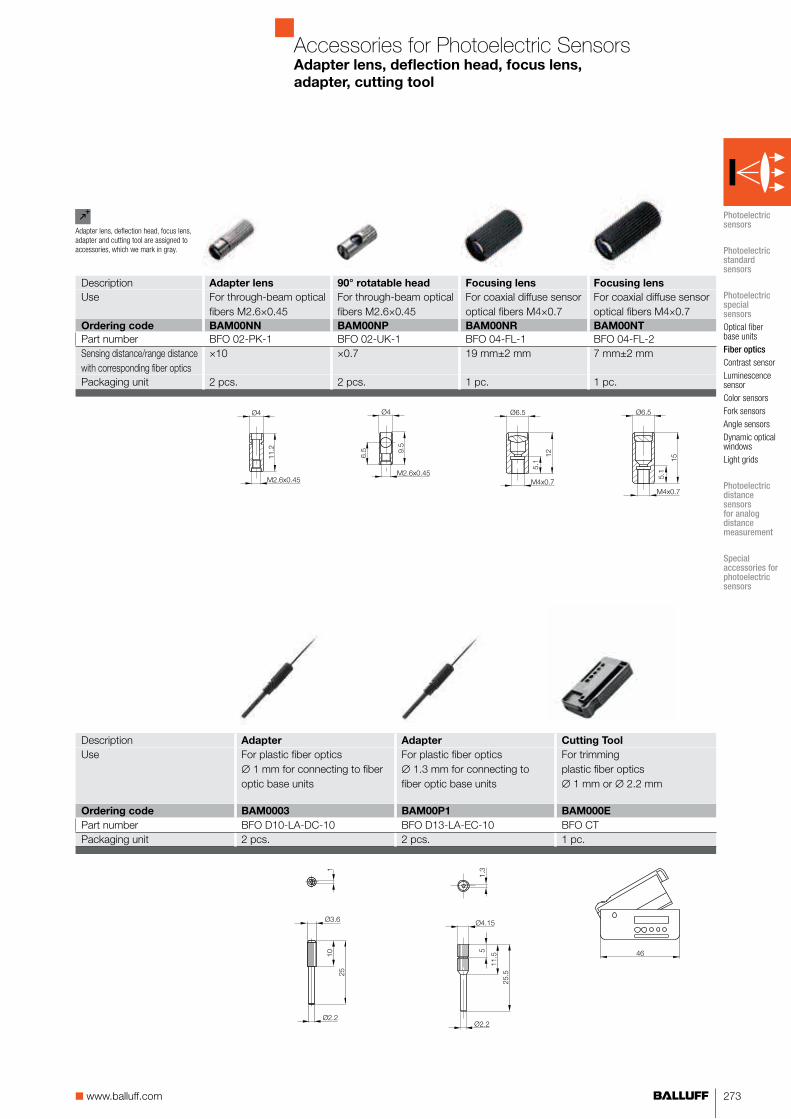
Accessories for Photoelectric SensorsAdapter lens, deflection head, focus lens,
adapter, cutting tool
Photoelectric sensors
Photoelectric standard sensors
Photoelectric special sensors
Optical fiber base units
Fiber optics
Contrast sensor
Luminescence sensor
Color sensors
Fork sensors
Angle sensors
Dynamic optical windows
Light grids
Photoelectric distance sensors for analog distance measurement
Special accessories for photoelectric sensors
Description Adapter lens 90° rotatable head Focusing lens Focusing lens
Use For through-beam optical fibers M2.6×0.45
For through-beam optical fibers M2.6×0.45
For coaxial diffuse sensor optical fibers M4×0.7
For coaxial diffuse sensor optical fibers M4×0.7
Ordering code BAM00NN BAM00NP BAM00NR BAM00NT
Part number BFO 02-PK-1 BFO 02-UK-1 BFO 04-FL-1 BFO 04-FL-2Sensing distance/range distance with corresponding fiber optics
×10 ×0.7 19 mm±2 mm 7 mm±2 mm
Packaging unit 2 pcs. 2 pcs. 1 pc. 1 pc.
Description Adapter Adapter Cutting Tool
Use For plastic fiber optics∅ 1 mm for connecting to fiber optic base units
For plastic fiber optics∅ 1.3 mm for connecting to fiber optic base units
For trimmingplastic fiber optics∅ 1 mm or ∅ 2.2 mm
Ordering code BAM0003 BAM00P1 BAM000E
Part number BFO D10-LA-DC-10 BFO D13-LA-EC-10 BFO CTPackaging unit 2 pcs. 2 pcs. 1 pc.
Adapter lens, deflection head, focus lens, adapter and cutting tool are assigned to accessories, which we mark in gray.

274 For more information, visit us online!
GlassFiber Optics
MZG type
Corrugated metal armorStrain reliefGlass optical fiber bundle
■ Resistant to high temperatures –20...+170 °C (up to +250 °C for a fixed installation)
■ Flexible■ Crush-resistant■ Resistant to hot swarf
UZG type
Polyurethane jacket Strain reliefGlass optical fiber bundle
■ Flexible■ Excellent chemical
resistance■ Does not become brittle from
oils and cooling emulsions■ Temperature resistance
–20...+85 °C
SMG type
Silicon protection jacketCorrugated metal armor with strain relief Glass optical fiber bundle■ Extended temperature range ■ –40...+150 °C■ Highly flexible■ Crush-resistant
The BFO 18 series of glass fiber optics are designed for series BOS 18M cylindrical sensors and are used wherever a high level of function reserve or chemical resistance is required. Likewise, tem-peratures over 200 °C pose no problem.
Various straight or right-angle versions are available with a polyure-thane jacket, corrugated metal armor or silicon protective jacket.
Photoelectric Special SensorsGlass fiber optics BFO 18

275■ www.balluff.com
Photoelectric Special SensorsGlass fiber optics BFO 18
Product overview
Type Max.
sensing
distance
Version Light exit Auto-
motive
approval
Page
For
BO
S 1
8M
-...
-1P
F-..
.
Thro
ugh-
beam
But
tons
Str
aigh
t
Rig
ht-a
ngle
Through-beam fiber optics
BFO001Z BFO 18A-LGG-MZG-10-0,5 400 mm ■ ■ 276
BFO0020 BFO 18A-LGG-MZG-10-1 400 mm ■ ■ 276
BFO0023 BFO 18A-LGG-SMG-10-0,5 400 mm ■ ■ 276
BFO0024 BFO 18A-LGG-SMG-10-1 400 mm ■ ■ 276
BFO001P BFO 18A-LFF-MZG-10-0,5 400 mm ■ ■ 276
BFO001R BFO 18A-LFF-MZG-10-1 400 mm ■ ■ 276
BFO001U BFO 18A-LFF-SMG-10-0,5 400 mm ■ ■ 276
BFO001W BFO 18A-LFF-SMG-10-1 400 mm ■ ■ 276
BFO000M BFO 18A-LAA-UZG-20-0,5 700 mm ■ ■ 277
BFO000N BFO 18A-LAA-UZG-20-1 700 mm ■ ■ 277
BFO000F BFO 18A-LAA-MZG-20-0,5 700 mm ■ ■ 277
BFO000H BFO 18A-LAA-MZG-20-1 700 mm ■ ■ 277
BFO000Z BFO 18A-LCC-UZG-20-1 700 mm ■ ■ 277
BFO000U BFO 18A-LCC-SMG-20-0,5 700 mm ■ ■ 277
BFO000W BFO 18A-LCC-SMG-10-1 700 mm ■ ■ 277
BFO001N BFO 18A-LEE-UZG-20-0,5 700 mm ■ ■ 277
BFO001H BFO 18A-LEE-UZG-20-1 700 mm ■ ■ 277
BFO0013 BFO 18A-LEE-MZG-20-0,5 700 mm ■ ■ 277
BFO0014 BFO 18A-LEE-MZG-20-1 700 mm ■ ■ 277
BFO0019 BFO 18A-LEE-SMG-20-0,5 700 mm ■ ■ 277
BFO001A BFO 18A-LEE-SMG-20-1 700 mm ■ ■ 277
BFO003Y BFO 18V-LCC-MZG-23-0,5 2000 mm ■ ■ ■ 277
BFO0042 BFO 18V-LCC-SMG-23-0,5 2000 mm ■ ■ ■ 277
BFO004C BFO 18V-LDD-SMG-23-0,5 2000 mm ■ ■ ■ 277
BFO004F BFO 18V-LDD-SMG-23-1 2000 mm ■ ■ ■ 277
Diffuse sensor fiber optics
BFO003R BFO 18A-XAG-MZG-15-0,5 50 mm ■ ■ 278
BFO003T BFO 18A-XAG-MZG-15-1 50 mm ■ ■ 278
BFO003H BFO 18A-XAF-MZG-15-0,5 50 mm ■ ■ 278
BFO003J BFO 18A-XAF-MZG-15-1 50 mm ■ ■ 278
BFO003M BFO 18A-XAF-SMG-15-0,5 50 mm ■ ■ 278
BFO003N BFO 18A-XAF-SMG-15-1 50 mm ■ ■ 278
BFO002M BFO 18A-XAA-UZG-30-0,5 100 mm ■ ■ 279
BFO002N BFO 18A-XAA-UZG-30-1 100 mm ■ ■ 279
BFO0026 BFO 18A-XAA-MZG-30-0,5 100 mm ■ ■ 279
BFO0027 BFO 18A-XAA-MZG-30-1 100 mm ■ ■ 279
BFO002F BFO 18A-XAA-SMG-30-0,5 100 mm ■ ■ 279
BFO002H BFO 18A-XAA-SMG-30-1 100 mm ■ ■ 279
BFO002W BFO 18A-XAC-SMG-30-1 100 mm ■ ■ 279
BFO002U BFO 18A-XAC-SMG-30-0,5 100 mm ■ ■ 279
BFO003C BFO 18A-XAE-UZG-30-0,5 100 mm ■ ■ 279
BFO003E BFO 18A-XAE-UZG-30-1 100 mm ■ ■ 279
BFO0031 BFO 18A-XAE-MZG-30-0,5 100 mm ■ ■ 279
BFO0032 BFO 18A-XAE-MZG-30-1 100 mm ■ ■ 279
BFO0037 BFO 18A-XAE-SMG-30-0,5 100 mm ■ ■ 279
BFO0038 BFO 18A-XAE-SMG-30-1 100 mm ■ ■ 279
BFO004M BFO 18V-XAC-MZG-30-0,5 200 mm ■ ■ ■ 279
BFO004P BFO 18V-XAC-SMG-30-0,5 200 mm ■ ■ ■ 279
BFO004R BFO 18V-XAC-SMG-30-1 200 mm ■ ■ ■ 279
BFO004U BFO 18V-XAD-MZG-30-0,5 200 mm ■ ■ ■ 279
BFO004Y BFO 18V-XAD-SMG-30-0,5 200 mm ■ ■ ■ 279
BFO004Z BFO 18V-XAD-SMG-30-1 200 mm ■ ■ ■ 279
■ Ordering code
■ Part number
Photoelectric sensors
Photoelectric standard sensors
Photoelectric special sensors
Optical fiber base units
Fiber optics
Contrast sensor
Luminescence sensor
Color sensors
Fork sensors
Angle sensors
Dynamic optical windows
Light grids
Photoelectric distance sensors for analog distance measurement
Special accessories for photoelectric sensors

For more information, visit us online!276
Through-beam sensor with
BOS 18M-...-PD-.. Range 100 mm 100 mm
BOS 18M-...-1PF-... Range 400 mm 400 mm
BOS 30M-... RangeUZG type0.5 m
Ordering code
Part numberUZG type1 m
Ordering code
Part numberMZG type0.5 m
Ordering code BFO001Z BFO001P
Part number BFO 18A-LGG-MZG-10-0,5 BFO 18A-LFF-MZG-10-0,5MZG type1 m
Ordering code BFO0020 BFO001R
Part number BFO 18A-LGG-MZG-10-1 BFO 18A-LFF-MZG-10-1SMG type0.5 m
Ordering code BFO0023 BFO001U
Part number BFO 18A-LGG-SMG-10-0,5 BFO 18A-LFF-SMG-10-0,5SMG type1 m
Ordering code BFO0024 BFO001W
Part number BFO 18A-LGG-SMG-10-1 BFO 18A-LFF-SMG-10-1Glass optical fiber bundle diameter 1 mm 1 mmMax. tension on optical fibers and connection parts 80 N 80 NMin. bending radius 60 mm 60 mmCan be used with BOS 18M-PA-1PD... Yes Yes
BOS 18M-PU-1PD-SA1.../-SA4.../-SA5... Yes (remove adapter disk)
Yes (remove adapter disk)
BOS 18M-GU-1PF-... Yes (remove adapter disk)
Yes (remove adapter disk)
BOS 18M-PA-1PF-... Yes Yes
BOS 30M-...(use BFO 30-A1 adapter)
No No
Photoelectric Special SensorsGlass fiber optics BFO 18
Through-beam
Mounting instruction
BOS 30M with BFO 18V
Additional lengths available (in 0.5 m increments)! Please submit an inquiry.
Please append the desired length L of the fiber optics cable to the ordering code.Adjustments from 0.5 m to max. 2 m possible. Example: BFO 18...-30-0,5 for 0.5 m fiber lengthBFO 18...-30-2 for 2 m fiber length
Important!
With a fiber optic through-beam sensor, the base unit's normally open signal switches to a normally closed signal!
Remove adapter disk from fiber optics!
Adapter BFO 30-A1
GlassFiber Optics

277■ www.balluff.com
200 mm 200 mm 200 mm 200 mm 200 mm
700 mm 700 mm 700 mm
2000 mm 2000 mm
BFO000M BFO001N
BFO 18A-LAA-UZG-20-0,5 BFO 18A-LEE-UZG-20-0,5BFO000N BFO000Z BFO001H
BFO 18A-LAA-UZG-20-1 BFO 18A-LCC-UZG-20-1 BFO 18A-LEE-UZG-20-1BFO000F BFO0013 BFO003Y
BFO 18A-LAA-MZG-20-0,5 BFO 18A-LEE-MZG-20-0,5 BFO 18V-LCC-MZG-23-0,5BFO000H BFO0014
BFO 18A-LAA-MZG-20-1 BFO 18A-LEE-MZG-20-1BFO000U BFO0019 BFO0042 BFO004C
BFO 18A-LCC-SMG-20-0,5 BFO 18A-LEE-SMG-20-0,5 BFO 18V-LCC-SMG-23-0,5 BFO 18V-LDD-SMG-23-0,5BFO000W BFO001A BFO004F
BFO 18A-LCC-SMG-10-1 BFO 18A-LEE-SMG-20-1 BFO 18V-LDD-SMG-23-12 mm 2 mm 2 mm 2 mm 2 mm80 N 80 N 80 N 80 N 80 N60 mm 60 mm 60 mm 60 mm 60 mmYes Yes Yes No No
Yes (remove adapter disk)
Yes (remove adapter disk)
Yes (remove adapter disk)
Yes (remove adapter disk)
Yes (remove adapter disk)
Yes (remove adapter disk)
Yes (remove adapter disk)
Yes (remove adapter disk)
No No
Yes Yes Yes No No
No No No Yes (remove adapter disk)
Yes (remove adapter disk)
Photoelectric Special SensorsGlass fiber optics BFO 18
Through-beam
15 15
Ø16.6
Ø16.6
Photoelectric sensors
Photoelectric standard sensors
Photoelectric special sensors
Optical fiber base units
Fiber optics
Contrast sensor
Luminescence sensor
Color sensors
Fork sensors
Angle sensors
Dynamic optical windows
Light grids
Photoelectric distance sensors for analog distance measurement
Special accessories for photoelectric sensors

For more information, visit us online!278
Remove adapter disk from fiber optics!
Diffuse sensor with BOS 18M-...-PD-.../BOS 18M-...-1PF-... 10 mm/50 mm 10 mm/50 mm
BOS 30M-...Retroreflective sensor with
BOS 18M-...-PD-.../BOS 18M-...-1PF-... 300 mm/1000 mm 300 mm/1000 mm
BOS 30M-...UZG type0.5 m
Ordering code
Part numberUZG type1 m
Ordering code
Part numberMZG type0.5 m
Ordering code BFO003R BFO003H
Part number BFO 18A-XAG-MZG-15-0,5 BFO 18A-XAF-MZG-15-0,5MZG type1 m
Ordering code BFO003T BFO003J
Part number BFO 18A-XAG-MZG-15-1 BFO 18A-XAF-MZG-15-1SMG type0.5 m
Ordering code BFO003M
Part number BFO 18A-XAF-SMG-15-0,5SMG type1 m
Ordering code BFO003N
Part number BFO 18A-XAF-SMG-15-1Glass optical fiber bundle diameter 1.5 mm 1.5 mmMax. tension on optical fibers and connection parts 80 N 80 NMin. bending radius 60 mm 60 mmCan be used with BOS 18M-PA-1PD... Yes Yes
BOS 18M-PU-1PD-SA1.../-SA4.../-SA5... Yes (remove adapter disk)
Yes (remove adapter disk)
BOS 18M-GU-1PF-... Yes (remove adapter disk)
Yes (remove adapter disk)
BOS 18M-PA-1PF-... Yes Yes
BOS 30M-... No No
Sensing distance with BOS 18M-PA-1PD... 10 mm 10 mmBOS 18M-PU-1PD-SA1.../-SA4.../-SA5... 10 mm 10 mmBOS 18M-...-1PF-... 50 mm 50 mmBOS 30M-...
Range with BOS 18M-PA-1PD... 300 mm 300 mmBOS 18M-PU-1PD-SA1.../-SA4.../-SA5... 300 mm 300 mmBOS 18M-...-1PF-... 1000 mm 1000 mmBOS 30M-...
Additional lengths available (in 0.5 m increments)! Please submit an inquiry.
Photoelectric Special SensorsGlass fiber optics BFO 18
Buttons
Mounting instruction
When using sensor BOS18M-GU-1PF-S4-Y or BOS 18M-PU-1PD-SA..., please remove the adapter disk from the fiber optics.
GlassFiber Optics

279■ www.balluff.com
20 mm/100 mm 20 mm/100 mm 20 mm/100 mm 20 mm 20 mm
200 mm 200 mm
500 mm/1000 mm 500 mm/1000 mm 500 mm/1000 mm 500 mm 500 mm
2000 mm 2000 mm
BFO002M BFO003C
BFO 18A-XAA-UZG-30-0,5 BFO 18A-XAE-UZG-30-0,5BFO002N BFO003E
BFO 18A-XAA-UZG-30-1 BFO 18A-XAE-UZG-30-1BFO0026 BFO0031 BFO004M BFO004U
BFO 18A-XAA-MZG-30-0,5 BFO 18A-XAE-MZG-30-0,5 BFO 18V-XAC-MZG-30-0,5 BFO 18V-XAD-MZG-30-0,5BFO0027 BFO0034
BFO 18A-XAA-MZG-30-1 BFO 18A-XAE-MZG-30-1BFO002F BFO002U BFO0037 BFO004P BFO004Y
BFO 18A-XAA-SMG-30-0,5 BFO 18A-XAC-SMG-30-0,5 BFO 18A-XAE-SMG-30-0,5 BFO 18V-XAC-SMG-30-0,5 BFO 18V-XAD-SMG-30-0,5BFO002H BFO002W BFO0039 BFO004R BFO004Z
BFO 18A-XAA-SMG-30-1 BFO 18A-XAC-SMG-30-1 BFO 18A-XAE-SMG-30-1 BFO 18V-XAC-SMG-30-1 BFO 18V-XAD-SMG-30-13 mm 3 mm 3 mm 3 mm 3 mm80 N 80 N 80 N 80 N 80 N60 mm 60 mm 60 mm 60 mm 60 mmYes Yes Yes No No
Yes (remove adapter disk)
Yes (remove adapter disk)
Yes (remove adapter disk)
Yes (remove adapter disk)
Yes (remove adapter disk)
Yes (remove adapter disk)
Yes (remove adapter disk)
Yes (remove adapter disk)
No No
Yes Yes Yes No No
No No No Yes (remove adapter disk)
Yes (remove adapter disk)
20 mm 20 mm 20 mm20 mm 20 mm 20 mm 20 mm 20 mm100 mm 100 mm 100 mm
200 mm 200 mm500 mm 500 mm 500 mm500 mm 500 mm 500 mm 500 mm 500 mm1000 mm 1000 mm 1000 mm
2000 mm 2000 mm
Photoelectric Special SensorsGlass fiber optics BFO 18
Buttons
M5
Ø4
8
3
15
L
Ø830
Ø20
M18x1
30
Sensing distances referenced to a 90% reflective Kodak gray card.Diffuse sensor with glass fiber optics as a retroreflective sensor:Ranges are referenced to BOS R-1 reflector.
Photoelectric sensors
Photoelectric standard sensors
Photoelectric special sensors
Optical fiber base units
Fiber optics
Contrast sensor
Luminescence sensor
Color sensors
Fork sensors
Angle sensors
Dynamic optical windows
Light grids
Photoelectric distance sensors for analog distance measurement
Special accessories for photoelectric sensors
When being used as a retroreflective sensor, twice the switching distance must be used as the object dead zone.

280 For more information, visit us online!
Contrast Sensor
Contrast sensors are high-resolution diffuse sensors that distinguish objects based on their gray values. Color, brightness and reflectivity have a strong effect on the measur-ing result.The measuring distance should be kept constant when gray values differ only slightly. The resolution of the sensor decreases with increasing sensing distance.Multiple series with various light types and functions are available for the multitude of uses for sensors.
Applications
■ Sensing markings on packaging material■ Synchronizing cutting or separating processes■ Checking for adhesive, ink and color■ Position checking of printing templates■ Sensing objects based on contrast
Photoelectric Special SensorsContrast sensors BKT

281■ www.balluff.com
Photoelectric Special SensorsContrast sensors BKT
Product overview
Type Sensing
distance
Light type Output Switch-
ing type
Switch-
ing fre-
quency
US Connection Features Page
Whi
te li
ght
Red
, gre
en a
nd b
lue
light
Lase
r lig
ht
PN
P t
rans
isto
r
NP
N t
rans
isto
r
Ana
log
outp
ut
Ligh
t sw
itchi
ng
Dar
k sw
itchi
ng
10
...3
0 V
DC
M8
plu
g, 4
-pin
M1
2 p
lug,
4-p
in
M1
2 p
lug,
5-p
in
Cab
le
for
adap
ting
fiber
opt
ics
Contrast sensors
BKT000A BKT 6K-001-P-S75 40...150 mm ■ ■ ■ ■ 1 kHz ■ ■ 283
BKT0008 BKT 6K-001-N-S75 40...150 mm ■ ■ ■ ■ 1 kHz ■ ■ 283
BKT0009 BKT 6K-001-P-02 40...150 mm ■ ■ ■ ■ 1 kHz ■ ■ 283
BKT0007 BKT 6K-001-N-02 40...150 mm ■ ■ ■ ■ 1 kHz ■ ■ 283
BKT000H BKT 18KF-001-P-S4 10 mm ■ ■ ■ ■ 5 kHz ■ ■ 285
BKT000F BKT 18KF-001-P-02 10 mm ■ ■ ■ ■ 5 kHz ■ ■ 285
BKT000Y BKT 21M-002-P-S4 19 mm ■ ■ ■ ■ 5 kHz ■ ■ 287
BKT000W BKT 21M-002-N-S4 19 mm ■ ■ ■ ■ 5 kHz ■ ■ 287
BKT0001 BKT 67M-001-U-S92 9 mm* ■ ■ ■ ■ ■ ■ 15 kHz ■ ■ 289
BKT0002 BKT 67M-002-U-S92 9 mm* ■ ■ ■ ■ ■ ■ 15 kHz ■ ■ 289
BKT0003 BKT 67M-003-U-S92 9 mm* ■ ■ ■ ■ ■ ■ 25 kHz ■ ■ 289
BKT0004 BKT 67M-004-U-S92 9 mm* ■ ■ ■ ■ ■ ■ 25 kHz ■ ■ 289
BKT0005 BKT 67M-005-U-S92 9 mm* ■ ■ ■ ■ ■ 30 kHz ■ ■ 289
BKT0006 BKT 67M-006-U-S92 9 mm* ■ ■ ■ ■ ■ 30 kHz ■ ■ 289
BKT000N BKT M-15C-U-S4 6...12 mm* ■ ■ ■ ■ ■ ■ 20 kHz ■ 291
BKT000R BKT M-45-U-S4 0...3 mm ■ ■ ■ ■ ■ ■ 20 kHz ■ ■ 291
*Longer sensing distances using interchangeable optics
■ Ordering code
■ Part number
Photoelectric sensors
Photoelectric standard sensors
Photoelectric special sensors
Optical fiber base units
Fiber optics
Contrast sensor
Luminescence sensor
Color sensors
Fork sensors
Angle sensors
Dynamic optical windows
Light grids
Photoelectric distance sensors for analog distance measurement
Special accessories for photoelectric sensors

282 For more information, visit us online!
Photoelectric Special SensorsLaser contrast sensor BKT 6K
The laser contrast sensor BKT 6K is designed to reliably detect small areas of contrast variances. Even the narrowest lines can be detected reliably in the optimum working range of 70...100 mm. Larger areas are capable of being detected outside this range.
Programming the sensor is easy using a teach-in button or control line.
Wiring diagrams
LaserContrast Sensor
Suitable connector
(please order separately)
More electrical accessories: You can find a large selection of plug con-nectors and connector cables in a wide variety of cable materials, colors and lengths in our Industrial Networking and Connectivity catalog.
Size Design Cable
material
Color Length Ordering
code
M8, 4-pin Straight PUR Black 2 m BCC02N2
M8, 4-pin Straight PVC Gray 2 m BCC02PL
M8, 4-pin Angled PUR Black 2 m BCC02NC
M8, 4-pin Angled PVC Gray 2 m BCC02PZ
Connectors without LED are suitable for PNP and NPN sensors.
olor Length Ordering
Recommended accessories
(please order separately)
You can find special accessories for diffuse sensors, such as reflectors, apertures, lenses, filters and deflection heads, in this catalog starting on page 379.
More mechanical accessories: You can find a large selection of mounting components of all types, such as clamping holders, mounting brackets and the Balluff mounting system BMS, in our Accessory Product Line catalog.
Description Ordering
code
Mounting bracket BAM00UH

283■ www.balluff.com
Series BKT 6K BKT 6K
Working distance 40...150 mm* 40...150 mm*
PNP NC/NO Ordering code BKT000A BKT0009
Part number BKT 6K-001-P-S75 BKT 6K-001-P-02NPN NC/NO Ordering code BKT0008 BKT0007
Part number BKT 6K-001-N-S75 BKT 6K-001-N-02Supply voltage UB 10...30 V DC 10...30 V DCNo-load supply current I0 max. ≤ 25 mA ≤ 25 mAOutput current 100 mA 100 mASwitching type Light/dark switching (selectable) Light/dark switching (selectable)Polarity reversal/short-circuit protected Yes/Yes Yes/YesSettings Teach-in Teach-inEmitter, light type Laser, red light Laser, red lightWavelength 650 nm 650 nmLaser class 2 2Light spot diameter 0.7 mm at the focus
(85 mm ± 15 mm) 0.7 mm at the focus (85 mm ± 15 mm)
Output function indicator Yellow LED Yellow LEDStability indicator Green LED Green LEDResponse time 0.5 ms 0.5 msSwitching frequency 1 kHz 1 kHzDegree of protection as per IEC 60529 IP 67 IP 67Ambient temperature Ta –20...+60 °C –20...+60 °CPermissible ambient light EN 60947-5-2 EN 60947-5-2Material Housing Impact-resistant ABS Impact-resistant ABS
Optical surface PMMA PMMAConnection M8 connector, 4-pin 2 m PVC cable,4×0.14 mm²
*Optimum working range for small markings: 70...100 mm
Photoelectric Special SensorsLaser contrast sensor BKT 6K
3.2 12
M8x1
21
10.7
2.6
4.2
10
42 4
24
9832
3.8
21
10.7
2.6
3.2
4.2
1217
9
532
4
24
Photoelectric sensors
Photoelectric standard sensors
Photoelectric special sensors
Optical fiber base units
Fiber optics
Contrast sensor
Luminescence sensor
Color sensors
Fork sensors
Angle sensors
Dynamic optical windows
Light grids
Photoelectric distance sensors for analog distance measurement
Special accessories for photoelectric sensors

284 For more information, visit us online!
Photoelectric Special SensorsContrast sensor BKT 18KF
The contrast sensor BKT 18KF operates with white light and draws attention with its ability to be configured simply at just the press of a button. It detects colored markings as well as gray levels on various surfaces. In the standard setting the sensor operates using dark switching. Precise configuration is available for slight contrast differences. The switching type can also be selected in this setting.
Function diagram
BN
BK
WH
BU
+UB
0 V
Wiring diagrams
BKT 18KF...P...Relative sensitivity
Sensing distance
Connector orientation
White LightContrast Sensor
Recommended accessories
(please order separately)
You can find special accessories for diffuse sensors, such as reflectors, apertures, lenses, filters and deflection heads, in this catalog starting on page 379.
More mechanical accessories: You can find a large selection of mounting components of all types, such as clamping holders, mounting brackets and the Balluff mounting system BMS, in our Accessory Product Line catalog.
Suitable connector
(please order separately)
More electrical accessories: You can find a large selection of plug con-nectors and connector cables in a wide variety of cable materials, colors and lengths in our Industrial Networking and Connectivity catalog.
Size Design Cable
material
Color Length Ordering
code
M12, 4-pin Straight PUR Black 2 m BCC032F
M12, 4-pin Straight PVC Gray 2 m BCC0367
M12, 4-pin Angled PUR Black 2 m BCC032Y
M12, 4-pin Angled PVC Gray 2 m BCC036N
Connectors without LED are suitable for PNP and NPN sensors.
Description Ordering
code
1 Mounting bracket BAM00RY
2 Mounting clamp BAM00T3
1 2
)
11

285■ www.balluff.com
Series BKT BKT
Working distance 10 mm±2 mm 10 mm±2 mm
PNP NC/NO Ordering code BKT000H BKT000F
Part number BKT 18KF-001-P-S4 BKT 18KF-001-P-02Supply voltage UB 10...30 V DC 10...30 V DCNo-load supply current I0 max. ≤ 25 mA ≤ 25 mAOutput current 100 mA 100 mASwitching type Light and dark switching Light and dark switchingPolarity reversal/short-circuit protected Yes/Yes Yes/YesSettings Teach-in Teach-inEmitter, light type LED, white light LED, white lightWavelength 400...700 nm 400...700 nmLight spot diameter ca. 4.5 mm 10 mm ca. 4.5 mm 10 mm Output function indicator Yellow LED Yellow LEDPower/error indicator Green/red LED Green/red LEDResponse time 100 μs 100 μsSwitching frequency 5 kHz 5 kHzDegree of protection as per IEC 60529 IP 67 IP 67Ambient temperature Ta –25...+55 °C –25...+55 °CPermissible ambient light EN 60947-5-2 EN 60947-5-2Material Housing PBT PBT
Optical surface PMMA PMMAConnection M12 connector, 4-pin 2 m PVC cable,4×0.14 mm²
24
14M18x1
M12x1
Ø3.8
81.5
45
25
34
10
10
LED
LED
24
14M18x1
2.5
77
34
25
45
Ø3.8
Photoelectric Special SensorsContrast sensor BKT 18KF
Photoelectric sensors
Photoelectric standard sensors
Photoelectric special sensors
Optical fiber base units
Fiber optics
Contrast sensor
Luminescence sensor
Color sensors
Fork sensors
Angle sensors
Dynamic optical windows
Light grids
Photoelectric distance sensors for analog distance measurement
Special accessories for photoelectric sensors

286 For more information, visit us online!
The BKT 21M contrast sensor uses white light and can be pro-grammed at the push of a button. It detects colored markings as well as gray levels on various surfaces. In its standard setting the sensor is dark switching (markings with less light intensity are de-tected as the background). Precise configuration is available for slight contrast differences. The switching type can also be selected in this setting.
Wiring diagrams
BKT 21M...P..
BKT 21M...N..
Function diagram
Relative sensitivity
Sensing distanceIndicators and operating elements
1 Output function indicator (yellow) 2 Power-/error indicator (green/red) 3 SET- button
1 2 3
Photoelectric Special SensorsContrast sensors BKT 21M
White Light Contrast Sensor
Recommended accessories
(please order separately)
You can find special accessories for diffuse sensors, such as reflectors, apertures, lenses, filters and deflection heads, in this catalog starting on page 379.
More mechanical accessories: You can find a large selection of mounting components of all types, such as clamping holders, mounting brackets and the Balluff mounting system BMS, in our Accessory Product Line catalog.
Description Ordering
code
1 Mounting bracket BAM00T9
2 Mounting bracket BAM00TA
3 Clamp holder BAM00TF
4 Clamp holder BAM00TH
Suitable connector
(please order separately)
More electrical accessories: You can find a large selection of plug con-nectors and connector cables in a wide variety of cable materials, colors and lengths in our Industrial Networking and Connectivity catalog.
Size Design Cable
material
Color Length Ordering
code
M12, 4-pin Straight PUR Black 2 m BCC032F
M12, 4-pin Straight PVC Gray 2 m BCC0367
M12, 4-pin Angled PUR Black 2 m BCC032Y
M12, 4-pin Angled PVC Gray 2 m BCC036N
Connectors without LED are suitable for PNP and NPN sensors.
1
2
3
4

287■ www.balluff.com
Series BKT
Working distance 19 mm±2 mm
PNP NC/NO Ordering code BKT000Y
Part number BKT 21M-002-P-S4NPN NC/NO Ordering code BKT000W
Part number BKT 21M-002-N-S4Supply voltage UB 10...30 V DCNo-load supply current I0 max. ≤ 30 mAOutput current 100 mASwitching type Light/dark switching (adjustable in precise mode)Polarity reversal/short-circuit protected Yes/YesSettings Teach-inEmitter, light type LED, white lightWavelength 400...700 nmLight spot diameter ca. 3.5 mm 19 mm Output function indicator Yellow LEDPower/error indicator Green/red LEDResponse time 0.1 msSwitching frequency 5 kHzTime function 20 ms off-delayDegree of protection as per IEC 60529 IP 67Ambient temperature Ta –25...+55 °CPermissible ambient light EN 60947-5-2Material Housing GD-Zn/Al
Optical surface GlassConnection M12 connector, 4-pin
Photoelectric Special SensorsContrast sensors BKT 21M
Photoelectric sensors
Photoelectric standard sensors
Photoelectric special sensors
Optical fiber base units
Fiber optics
Contrast sensor
Luminescence sensor
Color sensors
Fork sensors
Angle sensors
Dynamic optical windows
Light grids
Photoelectric distance sensors for analog distance measurement
Special accessories for photoelectric sensors

288 For more information, visit us online!
SeriesWorking distancePNP and NPN transistor (selectable)Vertical light spot
Ordering code
Part numberPNP and NPN transistor (selectable)Horizontal light spot
Ordering code
Part numberSupply voltage UB
No-load supply current I0 max.Output currentSwitching typeAnalog outputPolarity reversal/short-circuit protectedSettingsAdditional functionEmitter, light typeWavelengthLight spot diameterOutput function indicatorPower/error indicatorTime function displayResponse timeSwitching frequencyTime functionDegree of protection as per IEC 60529Ambient temperature Ta
Permissible ambient lightMaterial Housing
Optical surfaceConnection
*Longer sensing distance using interchangeable optics
Photoelectric Special SensorsContrast sensors BKT 67M
R-G-BContrast Sensor
Suitable connector
(please order separately)
More electrical accessories: You can find a large selection of plug con-nectors and connector cables in a wide variety of cable materials, colors and lengths in our Industrial Networking and Connectivity catalog.
Size Design Cable
material
Color Length Ordering
code
M12, 5-pin Straight PUR Black 5 m BCC098C
M12, 5-pin Angled PUR Black 5 m BCC08FC
Connectors without LED are suitable for PNP and NPN sensors.
lor Length Orderin
SET
Recommended accessories
(please order separately)
You can find special accessories for diffuse sensors, such as reflectors, apertures, lenses, filters and deflection heads, in this catalog starting on page 379.
More mechanical accessories: You can find a large selection of mounting components of all types, such as clamping holders, mounting brackets and the Balluff mounting system BMS, in our Accessory Product Line catalog.
Description Focal
length/focus
Ordering
code
1 Lens 18 mm BAM0120
2 Lens 9 mm BAM0121
3 Lens 28 mm BAM0122
4 Lens 50 mm BAM00P3
5 Intermediate ring
BAM00P2
40
With lens BAM0121 or standard lens BAM00P2
With lens BAM0120
1
3
2
1. Output function indicator2. Power indicator3. SET button
1 4
2 3
5
8 7 6
1. Output function indicator2. Power indicator3. Time delay indicator4. Button status indicator5. Switching threshold level indicator6. + button7. SET button8. - button
8 7 6
4
1
23
5
1. Output function indicator2. Power indicator3. Time delay indicator4. Button status indicator5. Scattered quantity of light indicator6. + button7. SET button8. - button
Indicators and operating elements
1
2
3
4
5 GY
BU
+US
0 V
Dark/LightRemote connectionNPN/PNP output
Wiring diagram
Relative responsiveness based on object distance
1 2
3 4
5

289■ www.balluff.com
BKT BKT BKT
9 mm* ± 3 mm 9 mm* ± 3 mm 9 mm* ± 3 mm
BKT0001 BKT0003 BKT0005
BKT 67M-001-U-S92 BKT 67M-003-U-S92 BKT 67M-005-U-S92BKT0002 BKT0004 BKT0006
BKT 67M-002-U-S92 BKT 67M-004-U-S92 BKT 67M-006-U-S9210...30 V DC 10...30 V DC 10...30 V DC≤ 50 mA ≤ 85 mA ≤ 35 mA100 mA 100 mA 100 mALight/Dark (automatic) Light/Dark (automatic) Light/Dark (automatic)1...3 V 1...3 VYes/Yes Yes/Yes Yes/YesTeach-in button 3 teach-in buttons 3 teach-in buttons
Segment display 4-digit displayRed, green and blue light Red, green and blue light Red, green and blue light630 nm/520 nm/465 nm 630 nm/520 nm/465 nm 630 nm/520 nm/465 nm1.5×5 mm 1.5×5 mm 1.5×5 mmYellow LED Yellow LED Yellow LEDGreen LED Green LED Green LED
Orange LED33 µS 25 µS 17 µS15 kHz 20 kHz 30 kHz
20 ms (can be activated)IP 67 IP 67 IP 67–10...+55 °C –10...+55 °C –10...+55 °CEN 60947-5-2 EN 60947-5-2 EN 60947-5-2Al Al AlPMMA PMMA PMMAM12 connector, 5-pin M12 connector, 5-pin M12 connector, 5-pin
Photoelectric Special SensorsContrast sensors BKT 67M
16.5 28 38.6
4.1 15.8
79
Ø24.9
28 43.4
22
4xM55
32
40
2xM5
32
3
60
Ø2515.8
M12x1
79
40
16.5 28 38.6 32
60
Ø2515.8
Ø24.9
15.84.1
2xM5
3
43.428
32
522
M12x1
4xM5
79
40
16.5 28 38.6 32
60
Ø2515.8
Ø24.9
15.84.1
2xM5
3
43.428
32
522
M12x1
4xM5
Photoelectric sensors
Photoelectric standard sensors
Photoelectric special sensors
Optical fiber base units
Fiber optics
Contrast sensor
Luminescence sensor
Color sensors
Fork sensors
Angle sensors
Dynamic optical windows
Light grids
Photoelectric distance sensors for analog distance measurement
Special accessories for photoelectric sensors

290 For more information, visit us online!
Photoelectric Special SensorsContrast sensor BKT M
The BKT M... series of contrast sensors are also available with white light. Models with either a round light spot or an optical fiber connection are available.
Features
■ Round light spot■ White light■ Automatic setting of light/dark switching■ Time delay and key lock■ Interchangeable optics (straight and 90°)■ Analog output
Analog output
Wiring diagram
PNP/NPN
BKT M...
Function diagrams
40
Working distance (mm)
Rel
ativ
e se
nsiti
vity
(%)
Standard lens (9 mm)
With lens BKT M-PK-1 (18 mm) Optical fibers
Recommended accessories
(please order separately)
You can find special accessories for diffuse sensors, such as reflectors, apertures, lenses, filters and deflection heads, in this catalog starting on page 379.
More mechanical accessories: You can find a large selection of mounting components of all types, such as clamping holders, mounting brackets and the Balluff mounting system BMS, in our Accessory Product Line catalog.
White LightContrast Sensor
Suitable connector
(please order separately)
More electrical accessories: You can find a large selection of plug con-nectors and connector cables in a wide variety of cable materials, colors and lengths in our Industrial Networking and Connectivity catalog.
Size Design Cable
material
Color Length Ordering
code
M12, 4-pin Straight PUR Black 2 m BCC032F
M12, 4-pin Straight PVC Gray 2 m BCC0367
M12, 4-pin Angled PUR Black 2 m BCC032Y
M12, 4-pin Angled PVC Gray 2 m BCC036N
Connectors without LED are suitable for PNP and NPN sensors.
Description Ordering
code
1 Optical fibers BFO0008
2 Lens BAM0120
1
2
S
MM
2222

291■ www.balluff.com
Series BKT BKT
Working distance 9 mm± 3 mm
Working distance with lens PK-1 18 mm± 4 mm
Working distance with optical fibers (diffuse) 0...3 mm
PNP/NPN NC/NO Round spot Ordering code BKT000N
Part number BKT M-15C-U-S4PNP/NPN NC/NO for optical
fibersOrdering code BKT000R
Part number BKT M-45-U-S4Supply voltage UB 10...30 V DC 10...30 V DCNo-load supply current I0 max. ≤ 80 mA ≤ 80 mAOutput current 200 mA 200 mASwitching type Light/dark switching (selectable) Light/dark switching (selectable)Analog output 0...5.5 V DC* 0...5.5 V DC*Polarity reversal/short-circuit protected Yes/Yes Yes/YesSettings Teach-in Teach-inAdditional function Disable buttons Disable buttonsEmitter, light type LED, white light LED, white lightWavelength 400...700 nm 400...700 nmReady indicator Green LED Green LEDOutput function indicator Red LED Red LEDResponse time 25μs 25μsSwitching frequency 20 kHz 20 kHzTime function 20 ms off-delay selectable 20 ms off-delay selectable
Degree of protection as per IEC 60529 IP 67 IP 67Ambient temperature Ta –10...+55 °C –10...+55 °CPermissible ambient light EN 60947-5-2 EN 60947-5-2Material Housing GD-Zn GD-Zn
Optical surface Glass GlassConnection M12 connector, 4-pin M12 connector, 4-pin
2.5 V DC with 90% reflective Kodak gray card
Photoelectric Special SensorsContrast sensor BKT M
Photoelectric sensors
Photoelectric standard sensors
Photoelectric special sensors
Optical fiber base units
Fiber optics
Contrast sensor
Luminescence sensor
Color sensors
Fork sensors
Angle sensors
Dynamic optical windows
Light grids
Photoelectric distance sensors for analog distance measurement
Special accessories for photoelectric sensors

292 For more information, visit us online!
LuminescenceSensors
Photoelectric sensors usually detect the target or the desired target features themselves. If that is not possible, the object can be marked with fluorescent substances. These markings are invisible to the human eye, but are detected by luminescence sensors with their UV light. Luminescence sensors detect any kind of fluorescent substance, even if markings are applied lightly.
Applications
■ Logistics (marking, selecting)■ Assembly (guiding, monitoring, sorting)■ Packaging machines
(to monitor cutting, folding)■ Ceramics industry (e.g. positioning parts)■ Wood industry (e.g. checking the glue bead)■ Pharmaceuticals (control tasks in the manufacturing process)■ Textiles (e.g. guiding cuts) ■ Food industry
Photoelectric Special SensorsLuminescence sensors BLT

293■ www.balluff.com
Photoelectric Special SensorsLuminescence sensors BLT
Product overview
■ Ordering code
■ Part number
Type Sensing
distance
Light type Output Switching
type
Switching
frequency
US Connec-
tion
Page
UV
light
PN
P t
rans
isto
r
NP
N t
rans
isto
r
Ana
log
outp
ut
Ligh
t sw
itchi
ng
Dar
k sw
itchi
ng
10
...3
0 V
DC
M1
2 p
lug,
4-p
in
Cab
le
Luminescence sensors
BLT0004 BLT 18KF-001-P-S4 8...20 mm ■ ■ ■ ■ 1 kHz ■ ■ 295
BLT0003 BLT 18KF-001-P-02 8...20 mm ■ ■ ■ ■ 1 kHz ■ ■ 295
BLT0009 BLT 21M-001-P-S4 0...40 mm ■ ■ ■ ■ 2 kHz ■ ■ 297
BLT0008 BLT 21M-001-N-S4 0...40 mm ■ ■ ■ ■ 2 kHz ■ ■ 297
BLT0006 BLT M-15-U-S4 9...18 mm ■ ■ ■ ■ ■ ■ 1 kHz ■ ■ 299
BLT0005 BLT M-11-U-03 9...18 mm ■ ■ ■ ■ ■ ■ 1 kHz ■ ■ 299
BLT0007 BLT M-55-U-S4 20...40 mm ■ ■ ■ ■ ■ ■ 2 kHz ■ ■ 301
Photoelectric sensors
Photoelectric standard sensors
Photoelectric special sensors
Optical fiber base units
Fiber optics
Contrast sensor
Luminescence sensor
Color sensors
Fork sensors
Angle sensors
Dynamic optical windows
Light grids
Photoelectric distance sensors for analog distance measurement
Special accessories for photoelectric sensors

294 For more information, visit us online!
Photoelectric Special SensorsLuminescence sensors BLT 18KF
Function diagram
BN
BK
WH
BU
+UB
0 V
Wiring diagrams
BLT 18KF...P...
Relative sensitivity
Sensing distance
Connector orientation
The luminescence sensor BLT 18KF detects any type of lumines-cent markings on any surface and automatically adjusts to ambient conditions. The sensor is calibrated with the simple push of a button. (Markings with a luminescence greater than the background are detected.) A precise setting is available for slightly luminescent markings. The switching type can be freely selected in this case.
Recommended accessories
(please order separately)
You can find special accessories for diffuse sensors, such as reflectors, apertures, lenses, filters and deflection heads, in this catalog starting on page 379.
More mechanical accessories: You can find a large selection of mounting components of all types, such as clamping holders, mounting brackets and the Balluff mounting system BMS, in our Accessory Product Line catalog.
Suitable connector
(please order separately)
More electrical accessories: You can find a large selection of plug con-nectors and connector cables in a wide variety of cable materials, colors and lengths in our Industrial Networking and Connectivity catalog.
Size Design Cable
material
Color Length Ordering
code
M12, 4-pin Straight PUR Black 2 m BCC032F
M12, 4-pin Straight PVC Gray 2 m BCC0367
M12, 4-pin Angled PUR Black 2 m BCC032Y
M12, 4-pin Angled PVC Gray 2 m BCC036N
Connectors without LED are suitable for PNP and NPN sensors.
LuminescenceSensors
Description Ordering
code
1 Mounting bracket BAM00RY
2 Mounting clamp BAM00T3
12
11

295■ www.balluff.com
Series BLT BLT
Working range 8...20 mm 8...20 mm
PNP NC/NO Ordering code BLT0004 BLT0003
Part number BLT 18KF-001-P-S4 BLT 18KF-001-P-02Supply voltage UB 10...30 V DC 10...30 V DCNo-load supply current I0 max. ≤ 25 mA ≤ 25 mAOutput current 100 mA 100 mASwitching type Light and dark switching Light and dark switchingPolarity reversal/short-circuit protected Yes/Yes Yes/YesSettings Teach-in Teach-inEmitter, light type LED, UV LED, UVWavelength 370 nm 370 nmLight spot diameter approx. 3 mm at 20 mm approx. 3 mm at 20 mm Output function indicator Yellow LED Yellow LEDPower/error indicator Green/red LED Green/red LEDResponse time 0.5 ms 0.5 msSwitching frequency 1 kHz 1 kHzDegree of protection as per IEC 60529 IP 67 IP 67Ambient temperature Ta –25...+55 °C –25...+55 °CPermissible ambient light EN 60947-5-2 EN 60947-5-2Material Housing PBT PBT
Optical surface PMMA PMMAConnection M12 connector, 4-pin 2 m PVC cable, 4×0.14 mm²
Photoelectric Special SensorsLuminescence sensors BLT 18KF
24
14M18x1
M12x1
Ø3.8
81.5
45
25
34
10
10
LED
LED
24
14M18x1
2.5
77
34
25
45
Ø3.8
Photoelectric sensors
Photoelectric standard sensors
Photoelectric special sensors
Optical fiber base units
Fiber optics
Contrast sensor
Luminescence sensor
Color sensors
Fork sensors
Angle sensors
Dynamic optical windows
Light grids
Photoelectric distance sensors for analog distance measurement
Special accessories for photoelectric sensors

296 For more information, visit us online!
Function diagram
The luminescence sensor BLT 21M detects any type of lumines-cent markings on any surface and automatically adjusts to ambient conditions. The sensor is calibrated with the simple push of a button. (Markings with a luminescence greater than the background are detected.) A precise setting is available for slightly luminescent markings. The switching type can be freely selected in this case.
Relative sensitivity
Wiring diagrams
Indicators and operating elements
1 Output function indicator (yellow) 2 Power-/error indicator (green/red) 3 SET- button
1 2 3
Sensing distance
BLT 21M...P..
BLT 21M...N..
Recommended accessories
(please order separately)
You can find special accessories for diffuse sensors, such as reflectors, apertures, lenses, filters and deflection heads, in this catalog starting on page 379.
More mechanical accessories: You can find a large selection of mounting components of all types, such as clamping holders, mounting brackets and the Balluff mounting system BMS, in our Accessory Product Line catalog.
Photoelectric Special SensorsLuminescence sensors BLT 21M
Suitable connector
(please order separately)
More electrical accessories: You can find a large selection of plug con-nectors and connector cables in a wide variety of cable materials, colors and lengths in our Industrial Networking and Connectivity catalog.
Size Design Cable
material
Color Length Ordering
code
M8, 4-pin Straight PUR Black 2 m BCC02N2
M8, 4-pin Straight PVC Gray 2 m BCC02PL
M8, 4-pin Angled PUR Black 2 m BCC02NC
M8, 4-pin Angled PVC Gray 2 m BCC02PZ
Connectors without LED are suitable for PNP and NPN sensors.
Color Length Ordering
LuminescenceSensors
Description Ordering
code
1 Mounting bracket BAM00T9
2 Mounting bracket BAM00TA
3 Clamp holder BAM00TF
4 Clamp holder BAM00TH
1
2
3
4

297■ www.balluff.com
Series BLT
Working range 0...40 mm
PNP NC/NO Ordering code BLT0009
Part number BLT 21M-001-P-S4NPN NC/NO Ordering code BLT0008
Part number BLT 21M-001-N-S4Supply voltage UB 10...30 V DCNo-load supply current I0 max. ≤ 30 mAOutput current 100 mASwitching type Light and dark switching (adjustable in precise mode)Polarity reversal/short-circuit protected Yes/YesSettings Teach-inEmitter, light type LED, UVWavelength 370 nmLight spot diameter ca. 1.5 mm at 10 mm Output function indicator Yellow LEDPower/error indicator Green/red LEDResponse time 250 μsSwitching frequency 2 kHzTime function 20 ms off-delayDegree of protection as per IEC 60529 IP 67Ambient temperature Ta –10...+55 °CPermissible ambient light EN 60947-5-2Material Housing GD-Zn/Al
Optical surface GlassConnection M12 connector, 4-pin
Photoelectric Special SensorsLuminescence sensors BLT 21M
Photoelectric sensors
Photoelectric standard sensors
Photoelectric special sensors
Optical fiber base units
Fiber optics
Contrast sensor
Luminescence sensor
Color sensors
Fork sensors
Angle sensors
Dynamic optical windows
Light grids
Photoelectric distance sensors for analog distance measurement
Special accessories for photoelectric sensors

298 For more information, visit us online!
Photoelectric Special SensorsLuminescence sensors BLT M
The Balluff luminescence sensor BLT is equipped with a state-of-the-art UV source, which means no external UV lamp is needed. Controlled by a microcontroller, the sensor performs its evaluation via teach-in. By simply pressing a button, the BLT learns the difference between the fluorescent marking and the background. If the differ-ence is too slight and cannot be reliably discerned, this is indicated by an error message (flashing LED). The sensing distance is typically from 9 to 18 mm, but can be increased by using additional lenses.Configuring two internal DIP switches allows you to set a turn-off de-lay of 20 ms or disable the buttons. The PNP/NPN output wiring can also be configured. An analog signal in proportion to the reflected light rounds out the BLT's functions.
Analog output
Analog output
Wiring diagrams
PNP/NPN
PNP/NPN
BLT M-11...
BLT M-15...
Function diagram
Rel
ativ
e se
nsiti
vity
(%)
Working distance (mm)
With standard lens (9...18 mm)
With lens BKT M-PK-1 (15...30 mm)
Recommended accessories
(please order separately)
You can find special accessories for diffuse sensors, such as reflectors, apertures, lenses, filters and deflection heads, in this catalog starting on page 379.
More mechanical accessories: You can find a large selection of mounting components of all types, such as clamping holders, mounting brackets and the Balluff mounting system BMS, in our Accessory Product Line catalog.
Features
■ UV source: LED, 100,000 hour service life■ Push-button setting■ Automatic setting of light/dark switching■ Time delay selectable ■ Analog output 0...7 V DC standard■ Switchable M12 plug (3 positions)■ Button locking possible
Suitable connector
(please order separately)
More electrical accessories: You can find a large selection of plug con-nectors and connector cables in a wide variety of cable materials, colors and lengths in our Industrial Networking and Connectivity catalog.
Size Design Cable
material
Color Length Ordering
code
M12, 4-pin Straight PUR Black 2 m BCC032F
M12, 4-pin Straight PVC Gray 2 m BCC0367
M12, 4-pin Angled PUR Black 2 m BCC032Y
M12, 4-pin Angled PVC Gray 2 m BCC036N
Connectors without LED are suitable for PNP and NPN sensors.
LuminescenceSensors
Description Ordering
code
Lens BAM0120

299■ www.balluff.com
Series BLT BLT
Working range 9...18 mm 9...18 mm
Working range with lens PK-1 15...30 mm 15...30 mm
PNP Ordering code BLT0006 BLT0005
NPN NC/NO Part number BLT M-15-U-S4 BLT M-11-U-03Supply voltage UB 10...30 V DC 10...30 V DCNo-load supply current I0 max. ≤ 80 mA ≤ 80 mAOutput current 200 mA 200 mASwitching type Light/dark switching (selectable) Light/dark switching (selectable)Polarity reversal/short-circuit protected Yes/Yes Yes/YesAnalog output 0...7 V DC 0...7 V DCSettings Teach-in Teach-inAdditional functions Disable buttons Disable buttonsEmitter, light type LED, UV LED, UVWavelength 380 nm 380 nmLight spot diameter 5 mm at focal point 5 mm at focal pointReady indicator Green LED Green LEDOutput function indicator Red LED Red LEDResponse time 0.5 ms 0.5 msSwitching frequency 1 kHz 1 kHzTime function 20 ms off-delay
selectable20 ms off-delayselectable
Degree of protection as per IEC 60529 IP 67 IP 67Ambient temperature Ta –10...+55 °C –10...+55 °CPermissible ambient light EN 60947-5-2 EN 60947-5-2Material Housing GD-Zn GD-Zn
Optical surface Glass GlassConnection M12 connector, 4-pin 3 m cable, PVC
6×0.34 mm² with shield
Please note!
Lenses not interchangeable for BLT M.
Photoelectric Special SensorsLuminescence sensors BLT M
BKT M-15
Photoelectric sensors
Photoelectric standard sensors
Photoelectric special sensors
Optical fiber base units
Fiber optics
Contrast sensor
Luminescence sensor
Color sensors
Fork sensors
Angle sensors
Dynamic optical windows
Light grids
Photoelectric distance sensors for analog distance measurement
Special accessories for photoelectric sensors

300 For more information, visit us online!
The Balluff luminescence sensor BLT M-55-... is equipped with a high- power UV LED. Thus, large sensing distances can be achieved using special target objects. An adaptable optical fiber provides ad-ditional solution options for tight mounting conditions.
Features
■ High-power UV LED■ High switching frequency of 2 kHz■ Optical fiber compatibility■ Push-button setting■ Analog output 0...7 V DC standard
Wiring diagram
Analog output
PNP/NPN
BLT M-55-...
0
5
5
10
10
15
20
15
20
mm
5 30 mm25201510
Optical fibers
00
40
80
20
60
100 %
10 3020 40 50 mm
Function diagrams
Relative sensitivityDetection range
Sensing distance
Sensing distance
Photoelectric Special SensorsLuminescence sensors BLT M
Suitable connector
(please order separately)
More electrical accessories: You can find a large selection of plug con-nectors and connector cables in a wide variety of cable materials, colors and lengths in our Industrial Networking and Connectivity catalog.
Size Design Cable
material
Color Length Ordering
code
M12, 4-pin Straight PUR Black 2 m BCC032F
M12, 4-pin Straight PVC Gray 2 m BCC0367
M12, 4-pin Angled PUR Black 2 m BCC032Y
M12, 4-pin Angled PVC Gray 2 m BCC036N
Connectors without LED are suitable for PNP and NPN sensors.
Recommended accessories
(please order separately)
You can find special accessories for photoelectric sensors, such as reflectors, apertures, lenses, filters and deflection heads, in this catalog on page 379.
More mechanical accessories: You can find a large selection of mounting components of all types, such as clamping holders, mounting brackets and the Balluff mounting system BMS, in our Accessory Product Line catalog.
Description Ordering code
Optical fibers BFO LTS-...-TAF-00-_ _
LuminescenceSensors

301■ www.balluff.com
Series BLT
Working range 20...40 mm
Working range with optical fibers 0...30 mm
PNP/NPN NC/NO Ordering code BLT0007
Part number BLT M-55-U-S4Supply voltage UB 10...30 V DCNo-load supply current I0 max. ≤ 80 mAOutput current 200 mASwitching type Light/dark switching (selectable)Polarity reversal/short-circuit protected Yes/YesAnalog output 0...7 V DCSettings Teach-inAdditional functions Disable buttonsEmitter, light type LED, HP UVWavelength 370 nmLight spot diameter 3 mm at focal pointReady indicator Green LEDOutput function indicator Red LEDResponse time 250 μsSwitching frequency 2 kHzTime function 20 ms off-delay selectableDegree of protection as per IEC 60529 IP 67Ambient temperature Ta –10...+55 °CPermissible ambient light EN 60947-5-2Material Housing GD-Zn
Optical surface GlassConnection M12 connector, 4-pin
Please note! Lenses not interchangeable for BLT M.
Photoelectric Special SensorsLuminescence sensors BLT M
Light exit window
3-way positioning
Photoelectric sensors
Photoelectric standard sensors
Photoelectric special sensors
Optical fiber base units
Fiber optics
Contrast sensor
Luminescence sensor
Color sensors
Fork sensors
Angle sensors
Dynamic optical windows
Light grids
Photoelectric distance sensors for analog distance measurement
Special accessories for photoelectric sensors

302 For more information, visit us online!
Color Sensors
Applications
Color sensors open up a wide range of various applications, such as in the packaging industry, robotics, automation, quality assurance or in the process industry.Versatile color sensors can be used to simplify and speed up auto-mated processes, for detecting color nuance in rugs and textiles or for color markings on packaging or labels.
The BFS 26K and BFS 27K series of color sensors operate using pulsed white light, making them particularly insensitive to ambient light. The light reflected back from the object is received and pro-cessed by three different receivers (red, green, blue).
The various light spot geometry configurations of the respective sensors (round, rectangular or square) can reliably detect even the smallest color markings.Numerous special functions such as color scanning, pulse expan-sion and blanking input provide additional application flexibility.
Features
■ Microcontroller-based■ Pulsed white light■ Various light spot geometries■ 3 different colors can be identified at the same time■ 5-stage adjustable color tolerance
The BFS 27K with a clearly organized operating panel and large display enables various colors and the selection of all functions to be taught in easily using teach-in.Modes C (color type) and C+I (color type + intensity) as well as 10 tolerance levels can be set separately for all 3 channels. Pulse exten-sion of 0...40 ms can also be selected and is applied to all channels.Balluff Sensorware allows the set functions to be visualized over the RS485 interface.
■ Display■ Autocollimation■ Versions with high switching frequency or for dark colors■ Color type or color type + intensity operating modes■ Serial RS485 interface
Photoelectric Special SensorsColor sensors BFS

303■ www.balluff.com
Photoelectric Special SensorsColor sensors BFS
Product overview
Type Sensing
distance/
Range
Light
type
Output Switch-
ing type
Switch-
ing fre-
quency
US Connection Special
features
Page
Whi
te li
ght
3×
PN
P t
rans
isto
r
3×
Pus
h-pu
ll
RS
48
5 in
terf
ace
RS
23
2 in
terf
ace
Ligh
t sw
itchi
ng
Dar
k sw
itchi
ng
10
...3
0 V
DC
12
...2
8 V
DC
18
...3
0 V
DC
24
V
M1
2 p
lug,
8-p
in
M1
2 p
lug,
5-p
in
Cab
le
Col
or in
tens
ity m
easu
rem
ent
Col
or s
can
True
col
or
Color sensors
BFS0001 BFS 26K-PS-L01-S115 12...32 mm ■ ■ ■ 500 Hz ■ ■ ■ 305
BFS0002 BFS 26K-PS-L02-S115-C 15...30 mm ■ ■ ■ 500 Hz ■ ■ ■ 305
BFS0003 BFS 26K-PS-L03-S115-C 18...22 mm ■ ■ ■ 500 Hz ■ ■ ■ 305
BFS000F BFS 26K-GI-L04-S92 12...32 mm ■ ■ ■ 500 Hz ■ ■ 305
BFS0008 BFS 27K-PS-L01-S115 5...45 mm ■ ■ ■ 1.5 kHz ■ ■ ■ 307
BFS000A BFS 27K-PSR-L01-S115 5...45 mm ■ ■ ■ ■ 1.5 kHz ■ ■ ■ 307
BFS0009 BFS 27K-PS-L02-S115 5...45 mm ■ ■ ■ 500 Hz ■ ■ 307
BFS000C BFS 27K-PSR-L02-S115 5...45 mm ■ ■ ■ ■ 500 Hz ■ ■ ■ 307
BFS000L BFS 33M-GSS-F01-PU-02 400 mm ■ ■ ■ ■ 1.5 kHz ■ ■ ■ 309
■ Ordering code
■ Part number
Photoelectric sensors
Photoelectric standard sensors
Photoelectric special sensors
Optical fiber base units
Fiber optics
Contrast sensor
Luminescence sensor
Color sensors
Fork sensors
Angle sensors
Dynamic optical windows
Light grids
Photoelectric distance sensors for analog distance measurement
Special accessories for photoelectric sensors

304 For more information, visit us online!
SeriesWorking rangeDiffuse mode working rangeRetroreflective working range3× PNP Ordering code
Part number1× Push-pull, IO-Link Ordering code
Part numberSupply voltage UB
No-load supply current I0 max.Output currentSwitching typePolarity reversal/short-circuit protectedSettingsEmitter, light typeLight spot geometryLight spot diameterSensing distance toleranceColor resolution toleranceReady indicatorOutput function indicator Ch. 1...Ch. 3Output function indicator Tol. 1...Tol. 5 Ready delayResponse timeSwitching frequencyTime function
Degree of protection as per IEC 60529Ambient temperature Ta
Permissible ambient lightMaterial Housing
Optical surfaceConnection
Indicators and operating elements
Wiring diagrams
BFS 26K-PS...Two modes are available. 1. Normal mode "factory setting"
Disabling input: > 12 V = Buttons locked, < 3 V = Buttons not locked
2. External Teach-in setting using "special functions"
Confirm
+US
Scan input
External teach-in
0 V
+US
Scan input
0 V
SET button
Power-on indicator
Toggle button
Tolerance level indicator
Channel indicator
Color resolution/sensing distance diagram
Color resolution
Sensing distance
BFS 26K...-L03...
BFS 26K...-L02...
BFS 26K...-L01...
> 20% remission
Recommended accessories
(please order separately)
More mechanical accessories: You can find a large selection of mounting components of all types, such as clamping holders, mounting brackets and the Balluff mounting system BMS, in our Accessory Product Line catalog.
Photoelectric Special SensorsColor sensors BFS 26K
3
524
1 +US
TeachTrigger
PNP-L/NPN-D, IO-Link0 V
BFS 26K-GI...
Color Sensors
C S +/F
ESC
Tol.C
Tol.I
Conf.
SET
1 2 34
5 6 7
1. Power-on indicator2. Output function indicator/teach-in indicator3. Teach-in indicator (color range)4. Teach-in indicator (special function)
6. Setting, teaching in7. Advancing
5. Tolerance level/special function
Description Ordering
code
Mounting bracket BAM00TK
Suitable connector
(please order separately)
More electrical accessories: You can find a large selection of plug con-nectors and connector cables in a wide variety of cable materials, colors and lengths in our Industrial Networking and Connectivity catalog.
Size Design Cable
material
Color Length Ordering
code
M12, 8-pin Straight PUR Black 2 m BCC06K2
M12, 8-pin Angled PUR Black 2 m BCC06K5
Connectors without LED are suitable for PNP and NPN sensors.

305■ www.balluff.com
BFS 26K BFS 26K BFS 26K BFS 26K
12...32 mm 15...30 mm 18...22 mm 12...32 mm
50...200 mm
BFS0001 BFS0002 BFS0003
BFS 26K-PS-L01-S115 BFS 26K-PS-L02-S115-C BFS 26K-PS-L03-S115-CBFS000F
BFS 26K-GI-L04-S9212...28 V DC 12...28 V DC 12...28 V DC 18...30 V DC≤ 40 mA ≤ 40 mA ≤ 40 mA ≤ 40 mA100 mA 100 mA 100 mA 100 mALight switching Light switching Light switching Light/dark switching (selectable)Yes/Yes Yes/Yes Yes/Yes Yes/YesTeach-in Teach-in Teach-in Teach-inPulsed white light Pulsed white light Pulsed white light Pulsed white lightRound Square Rectangular RoundØ 4 mm at 22 mm sensing distance 2×2 mm at 22 mm sensing distance 5×1 mm at 22 mm sensing distance Ø 4 mm at 22 mm sensing distance±6 mm at Tol.3 ±5 mm at Tol.3 ±2 mm at Tol.3 ±6 mm at Tol C3 and Tol I2Adjustable in 5 levels Adjustable in 5 levels Adjustable in 5 levelsGreen LED Green LED Green LED3×Yellow LED 3×Yellow LED 3×Yellow LED3×Red LED 3×Red LED 3×Red LED300 ms 300 ms 300 ms 300 ms1 ms 1 ms 1 ms500 Hz 500 Hz 500 Hz 500 Hz (SIO mode)50 ms release delay selectable
50 ms release delay selectable
50 ms release delay selectable
50 ms release delay selectable
IP 67 IP 67 IP 67 IP 67–10...+55 °C –10...+55 °C –10...+55 °C –10...+55 °CEN 60947-5-2 EN 60947-5-2 EN 60947-5-2 EN 60947-5-2Impact-resistant ABS Impact-resistant ABS Impact-resistant ABS Impact-resistant ABSPMMA PMMA PMMA PMMAM12 connector, 8-pin M12 connector, 8-pin M12 connector, 8-pin M12 connector, 5-pin
Photoelectric Special SensorsColor Sensors BFS 26K
14.2
Rotates 270°
Rec
eive
r E
mitt
er
14.2
C S +/F
ESC
Tol.C
Tol.I
Conf.
SET
Rotates 270°
Rec
eive
r E
mitt
er
Photoelectric sensors
Photoelectric standard sensors
Photoelectric special sensors
Optical fiber base units
Fiber optics
Contrast sensor
Luminescence sensor
Color sensors
Fork sensors
Angle sensors
Dynamic optical windows
Light grids
Photoelectric distance sensors for analog distance measurement
Special accessories for photoelectric sensors

306 For more information, visit us online!
Photoelectric Special SensorsColor sensors BFS 27K
Variants
The BFS 27K-...-L01 with a switching frequency of 1.5 kHz is designed for color detection in fast processes, such as industrial packaging of food products or pharmaceutical products.The BFS 27K-...-L02 variant is distinguished by excellent color sensi-tivity for dark colors. This makes it outstanding for quality assurance and for parts detec-tion.
Operating modes
C Color type
In C mode the sensor uses increased depth of field (contrast). This is used for detecting colors on shiny, highly reflective or matte surfaces.
C+I Color type + intensity
In the C+I setting, color intensity is also evaluated. This allows even the finest color nuances to be distinguished. Even the finest gray levels can be detected.
Function diagrams
BFS 27K-...-L01
Dark blueBlackO
bjec
t refl
ectiv
ity
WhiteLight yellow
Working range
BFS 27K-...-L02
Wiring diagram
Operating panel and display
Setting keys
Output function LED-
Output LED-(Status)
Display4-digit
BFS 27K-PS...PNP
Only the variant BFS 27K-PSR...
BN
PK
WH
RD
GN
YE
GY
BU
+ U
Rx/Tx +
Rx/Tx –
SYNC/
0 V
B2
6
1
8
3
4
5
7
Q1
Q2
Q3
Color Sensors
Obj
ect r
eflec
tivity
Working range
Dark blueBlack
WhiteLight yellow
Recommended accessories
(please order separately)
More mechanical accessories: You can find a large selection of mounting components of all types, such as clamping holders, mounting brackets and the Balluff mounting system BMS, in our Accessory Product Line catalog.
Description Ordering
code
1 Mounting bracket BAM00TK
2 Adapter plate BAM00T7
3 Clamping block BAM00T3
Suitable connector
(please order separately)
More electrical accessories: You can find a large selection of plug con-nectors and connector cables in a wide variety of cable materials, colors and lengths in our Industrial Networking and Connectivity catalog.
Size Design Cable
material
Color Length Ordering
code
M12, 8-pin Straight PUR Black 2 m BCC06K2
M12, 8-pin Angled PUR Black 2 m BCC06K5
Connectors without LED are suitable for PNP and NPN sensors.
1
2
3

307■ www.balluff.com
Series BFS 27K BFS 27K
Diffuse mode working range 5...45 mm* 5...45 mm*
3× PNP Ordering code BFS0008 BFS0009
Part number BFS 27K-PS-L01-S115 BFS 27K-PS-L02-S1153× PNPRS485 interface
Ordering code BFS000A BFS000C
Part number BFS 27K-PSR-L01-S115 BFS 27K-PSR-L02-S115Supply voltage UB 10...30 V DC 10...30 V DCNo-load supply current I0 max. ≤ 60 mA ≤ 60 mAOutput current 100 mA 100 mASwitching type Light switching Light switchingPolarity reversal/short-circuit protected Yes/Yes Yes/YesSettings Teach-in Teach-inEmitter, light type LED, white light LED, white lightWavelength 400...700 nm 400...700 nmLight spot diameter ≥ 4 mm ≥ 4 mmTolerance levels 10 per channel (can be set) 10 per channel (can be set)Display 4-digit 7-segment display in green 4-digit 7-segment display in greenOutput function indicator Yellow LED Yellow LEDOutput indicator 3×Green LED 3×Green LEDResponse time 335 μs 5 ms (standard), 1 ms (fast)Switching frequency 1.5 kHz 100 Hz (standard), 500 Hz (fast)Time function Pulse stretching 0...40 ms Pulse stretching 0...40 msDegree of protection as per IEC 60529 IP 67 IP 67Ambient temperature Ta –10...+55 °C –10...+55 °CMaterial Housing ABS ABS
Optical surface Glass GlassConnection M12 connector, 8-pin M12 connector, 8-pin
Photoelectric Special SensorsColor sensors BFS 27K
31.7
Connector orientation
Software
The software for the R model (RS485) can be downloaded for free at our homepage www.balluff.de.
*see function diagrams
Select a product
Service
Downloads
Software
www.balluff.de
Photoelectric sensors
Photoelectric standard sensors
Photoelectric special sensors
Optical fiber base units
Fiber optics
Contrast sensor
Luminescence sensor
Color sensors
Fork sensors
Angle sensors
Dynamic optical windows
Light grids
Photoelectric distance sensors for analog distance measurement
Special accessories for photoelectric sensors

308 For more information, visit us online!
Photoelectric Special SensorsTrue color sensor BFS 33M
Color Sensors
For distinguishing between the smallest of color nuances at
the highest level
The True Color sensor BFS 33M is in a completely different league to conventional RGB sensors. Thanks to its high resolution, it not only detects colors but can also reliably distinguish between nuances. The True Color sensor thus detects, for instance minimal color deviations in injection molded parts. And it can also tell if a metal enters production polished or unpolished. Faded colors or poor print quality are detected in an instant and separated. It thus opens up completely new dimensions in quality control. The sensor uses three digital outputs and a serial interface to perform evaluations. The lab color space values are transmitted directly via this interface.
Recommended accessories
(please order separately)
More mechanical accessories: You can find a large selection of mounting components of all types, such as clamping holders, mounting brackets and the Balluff mounting system BMS, in our Accessory Product Line catalog.
Description Ordering
code
1 Optical fiber M4 (coaxial), 2 m long BFO00C9
2 Optics (short-range), 7 mm, screwed onto M4 optical fiber
BAM00NT
3 Optical fiber M6 (coaxial), 1 m long BFO00FP
4 Optical fiber M6 (coaxial), 2 m long BFO00C4
5 Optical fiber M6 (coaxial), 5 m long BFO00FN
6 Optics (adjustable), 200 mm sensing distance, screwed onto M6 optical fiber
BAM01U2
7 Optics (long-range), 400 mm sensing distance, screwed onto M6 optical fiber
BAM01PA
! Interface cable (shielded) BCC0ARP
" RS232/USB interface converter BAE009A
2
7
1
3−5
6
!
"
Features
■ Detection of and distinguishing between a random number of colors
■ Reliably distinguishes between the smallest of color nuances■ Large sensing distance up to 400 mm■ Simple configuration and visualization using software■ Robust metal housing
Industries
■ Automotive industry■ Plastics processing■ Packaging industry■ Handling and assembly■ Printing industry■ Wood processing

309■ www.balluff.com
Series BFS 33M
Working range up to 400 mm (with additional optics)
3× Push-pullRS 232 interface
Ordering code BFS000L
Part number BFS 33M-GSS-F01-PU-02Supply voltage UB 24 V DC ±10%No-load supply current I0 max. 40 mAOutput current 30 mAPolarity reversal/short-circuit protected Yes/YesSettings via softwareEmitter, light type LED, white lightColor space CIELabLight spot diameter Depends on the fiber opticsColor resolution tolerance Adjustable (software)Resolution 8 amplifier stages of 12 bits eachColor resolution < 0.5 dERepeat accuracy < 1 dEReady indicator Green LEDOutput function indicator Ch. 1...Ch. 3 3× Yellow LED (binary encoding)Response time 0.33 msSwitching frequency 1.5 kHzDegree of protection as per IEC 60529 IP 54Ambient temperature Ta +10...+55 °CPermissible ambient light EN 60947-5-2Housing material Al coatedConnection 2 m PUR cable, 5×0.25 mm²
M4 17 26.5
7.5
33.4
52
29
3
Ø4.2
11
23
42
58.3
58
21
7.5
Photoelectric Special SensorsTrue color sensor BFS 33M
BN
BK
GY
WH
BU
+US
Out 1Out 2Out 30 V
Wiring diagram
Photoelectric sensors
Photoelectric standard sensors
Photoelectric special sensors
Optical fiber base units
Fiber optics
Contrast sensor
Luminescence sensor
Color sensors
Fork sensors
Angle sensors
Dynamic optical windows
Light grids
Photoelectric distance sensors for analog distance measurement
Special accessories for photoelectric sensors

310 For more information, visit us online!
Fork Sensors
Through-beam sensors are unsurpassed in their accuracy, their ability to distinguish small parts and fine detail and their operating reliability. However, they do take some time to install and configure. This does not apply to fork sensors, since the emitter and receiver are already installed and easy to adjust. Nevertheless, their accuracy, ability to distinguish small parts and fine detail and their operating re-liability is outstanding. Laser fork sensors achieve the best results in these kinds of tasks. Balluff laser through-beam fork sensors are ide-ally used for precisely positioning and reliably detecting fast-moving processes and small parts. This opens a vast range of applications in robotics and automation.
Photoelectric Special SensorsFork sensors BGL
Features
■ Integrated electronic evaluation unit■ Rugged metal housing■ Glass optical surface■ High resolution■ Available in red light, laser light, IR or pin point■ Identical housing dimensions for all light types■ 10×10 mm fork arm, even for large fork openings■ stackable■ Laser Class 1
Applications
■ Parts sensing on conveyor and feed belts■ Label sensing on transparent backing material■ Part dimension checking■ Counting parts in assembly lines■ Tool break monitoring■ Position checking■ Feed control on automatic assembly equipment■ Checking for completeness (e.g. connector pins)■ Level monitoring of containers■ Handling and assembly

311■ www.balluff.com
Photoelectric Special SensorsFork sensors BGL
Product overview
Type Fork
opening
Resolu-
tion
Light type Output Switch-
ing
type
Switch-
ing fre-
quency
US Connec-
tion
Features Page
Red
light
Red
light
, pin
poi
nt
Lase
r lig
ht
Infr
ared
Red
and
gree
n lig
ht
PNP
tran
sist
or
DSC
(Dyn
amic
Sen
sor
Con
trol
)
Ligh
t sw
itchi
ng
Dar
k sw
itchi
ng
10...
30 V
DC
M8
plug
, 3-p
in
M8
plug
, 4-p
in
Tran
spar
ency
det
ectio
n
Flui
d de
tect
ion
Fork sensors
BGL001W BGL 5A-001-S49 5 mm 0.3 mm ■ ■ ■ ■ 3 kHz ■ ■ 312
BGL001Z BGL 5A-005-S49 5 mm 0.2 mm ■ ■ ■ ■ 5 kHz ■ ■ 316
BGL0021 BGL 5A-007-S49 5 mm 0.8 mm ■ ■ ■ ■ 3 kHz ■ ■ 320
BGL0001 BGL 10A-001-S49 10 mm 0.3 mm ■ ■ ■ ■ 3 kHz ■ ■ 312
BGL0003 BGL 10A-005-S49 10 mm 0.2 mm ■ ■ ■ ■ 5 kHz ■ ■ 316
BGL0005 BGL 10A-007-S49 10 mm 0.8 mm ■ ■ ■ ■ 3 kHz ■ ■ 320
BGL000R BGL 20A-001-S49 20 mm 0.3 mm ■ ■ ■ ■ 1.5 kHz ■ ■ 313
BGL000U BGL 20A-005-S49 20 mm 0.2 mm ■ ■ ■ ■ 5 kHz ■ ■ 317
BGL000Y BGL 20A-007-S49 20 mm 0.8 mm ■ ■ ■ ■ 2 kHz ■ ■ 321
BGL0016 BGL 30A-001-S49 30 mm 0.3 mm ■ ■ ■ ■ 1.5 kHz ■ ■ 313
BGL0019 BGL 30A-003-S49 30 mm 50 µm ■ ■ ■ ■ 5 kHz ■ ■ 324
BGL001C BGL 30A-005-S49 30 mm 0.2 mm ■ ■ ■ ■ 5 kHz ■ ■ 317
BGL001F BGL 30A-007-S49 30 mm 0.8 mm ■ ■ ■ ■ 2 kHz ■ ■ 321
BGL003J BGL 30A-011-S49 30 mm 0.6 mm ■ ■ ■ ■ 2 kHz ■ ■ ■ 326
BGL003N BGL 30A-013-S49 30 mm 0.8 mm ■ ■ ■ ■ ■ 200 Hz ■ ■ 326
BGL001J BGL 50A-001-S49 50 mm 0.4 mm ■ ■ ■ ■ 1.5 kHz ■ ■ 313
BGL001M BGL 50A-003-S49 50 mm 80 µm ■ ■ ■ ■ 5 kHz ■ ■ 325
BGL001P BGL 50A-005-S49 50 mm 0.3 mm ■ ■ ■ ■ 5 kHz ■ ■ 317
BGL001T BGL 50A-007-S49 50 mm 1.0 mm ■ ■ ■ ■ 2 kHz ■ ■ 321
BGL003P BGL 50A-013-S49 50 mm 1.0 mm ■ ■ ■ ■ ■ 200 Hz ■ ■ 327
BGL0023 BGL 80A-001-S49 80 mm 0.4 mm ■ ■ ■ ■ 1.5 kHz ■ ■ 314
BGL0025 BGL 80A-003-S49 80 mm 0.1 mm ■ ■ ■ ■ 5 kHz ■ ■ 325
BGL0027 BDL 80A-005-S49 80 mm 0.4 mm ■ ■ ■ ■ 5 kHz ■ ■ 318
BGL0029 BDL 80A-007-S49 80 mm 1.2 mm ■ ■ ■ ■ 2 kHz ■ ■ 322
BGL002T BDL 80A-009-S49 80 mm 50 µm ■ ■ ■ ■ 5 kHz ■ ■ ■ 327
BGL003L BDL 80A-011-S49 80 mm 0.8 mm ■ ■ ■ ■ 2 kHz ■ ■ ■ 327
BGL003R BDL 80A-013-S49 80 mm 1.2 mm ■ ■ ■ ■ ■ 200 Hz ■ ■ 327
BGL0007 BGL 120A-001-S49 120 mm 0.5 mm ■ ■ ■ ■ 1.5 kHz ■ ■ 314
BGL0009 BGL 120A-003-S49 120 mm 0.15 mm ■ ■ ■ ■ 5 kHz ■ ■ 325
BGL000C BGL 120A-005-S49 120 mm 0.5 mm ■ ■ ■ ■ 5 kHz ■ ■ 318
BGL000F BGL 120A-007-S49 120 mm 1.5 mm ■ ■ ■ ■ 1 kHz ■ ■ 323
BGL000J BGL 180A-001-S49 180 mm 0.6 mm ■ ■ ■ ■ 1.5 kHz ■ ■ 315
BGL000L BGL 180A-005-S49 180 mm 0.6 mm ■ ■ ■ ■ 5 kHz ■ ■ 319
BGL000N BGL 180A-007-S49 180 mm 1.5 mm ■ ■ ■ ■ 2 kHz ■ ■ 323
BGL0010 BGL 220A-001-S49 220 mm 0.6 mm ■ ■ ■ ■ 1.5 kHz ■ ■ 315
BGL0012 BGL 220A-005-S49 220 mm 0.6 mm ■ ■ ■ ■ 5 kHz ■ ■ 319
BGL0014 BGL 220A-007-S49 220 mm 1.5 mm ■ ■ ■ ■ 2 kHz ■ ■ 323
BGL002L BGL 21-IR 2 mm 0.25 mm ■ ■ ■ ■ 25 kHz ■ ■ 329
BGL002M BGL 21-RG 2 mm 0.25 mm ■ ■ ■ ■ 25 kHz ■ ■ 329
NPN on request
■ Ordering code
■ Part number
Photoelectric sensors
Photoelectric standard sensors
Photoelectric special sensors
Optical fiber base units
Fiber optics
Contrast sensor
Luminescence sensor
Color sensors
Fork sensors
Angle sensors
Dynamic optical windows
Light grids
Photoelectric distance sensors for analog distance measurement
Special accessories for photoelectric sensors

For more information, visit us online!312
Series BGL BGL
Fork opening 5 mm 10 mm
Fork depth 17 mm 17 mm
PNP NO/NC Ordering code BGL001W BGL0001
Part number BGL 5A-001-S49 BGL 10A-001-S49Supply voltage UB 10...30 V DC 10...30 V DCNo-load supply current I0 max. ≤ 35 mA ≤ 35 mAOutput current 200 mA 200 mASwitching type Light/dark switching (selectable) Light/dark switching (selectable)Polarity reversal/short-circuit protected Yes/Yes Yes/YesSettings Potentiometer, 270° Potentiometer, 270°Emitter, light type LED, red light LED, red lightWavelength 640 nm 640 nmResolution (smallest discernible part) 0.3 mm 0.3 mmRepeat accuracy 20 μm 20 μmSwitching hysteresis ≤ 0.1 mm ≤ 0.1 mmOutput function indicator Yellow LED Yellow LEDResponse time 0.166 ms 0.166 msSwitching frequency 3 kHz 3 kHzDegree of protection as per IEC 60529 IP 67 IP 67Ambient temperature Ta –10...+60 °C –10...+60 °CAmbient light limit according to EN 60947-5-2 EN 60947-5-2Material Housing GD-Zn GD-Zn
Optical surface Glass GlassConnection M8 connector, 3-pin M8 connector, 3-pin
Connector orientation
Fork Sensors Red light
Photoelectric Special SensorsFork sensors BGL
5A, 10A
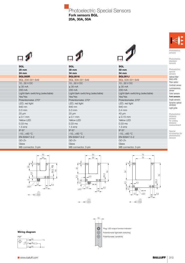
313■ www.balluff.com
BGL BGL BGL
20 mm 30 mm 50 mm
24 mm 34 mm 54 mm
BGL000R BGL0016 BGL001J
BGL 20A-001-S49 BGL 30A-001-S49 BGL 50A-001-S4910...30 V DC 10...30 V DC 10...30 V DC≤ 35 mA ≤ 35 mA ≤ 35 mA200 mA 200 mA 200 mALight/dark switching (selectable) Light/dark switching (selectable) Light/dark switching (selectable)Yes/Yes Yes/Yes Yes/YesPotentiometer, 270° Potentiometer, 270° Potentiometer, 270°LED, red light LED, red light LED, red light640 nm 640 nm 640 nm0.3 mm 0.3 mm 0.4 mm20 μm 20 μm 40 μm≤ 0.1 mm ≤ 0.1 mm ≤ 0.15 mmYellow LED Yellow LED Yellow LED0.33 ms 0.33 ms 0.33 ms1.5 kHz 1.5 kHz 1.5 kHzIP 67 IP 67 IP 67–10...+60 °C –10...+60 °C –10...+60 °CEN 60947-5-2 EN 60947-5-2 EN 60947-5-2GD-Zn GD-Zn GD-ZnGlass Glass GlassM8 connector, 3-pin M8 connector, 3-pin M8 connector, 3-pin
Wiring diagram
PNP
Potentiometer light/dark switching
Potentiometer, sensitivity
Plug, LED output function indicator
10
Photoelectric Special SensorsFork sensors BGL
20A, 30A, 50A
Photoelectric sensors
Photoelectric standard sensors
Photoelectric special sensors
Optical fiber base units
Fiber optics
Contrast sensor
Luminescence sensor
Color sensors
Fork sensors
Angle sensors
Dynamic optical windows
Light grids
Photoelectric distance sensors for analog distance measurement
Special accessories for photoelectric sensors
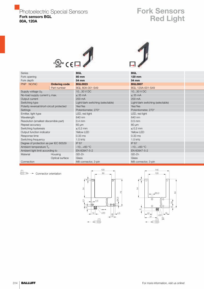
For more information, visit us online!314
Series BGL BGL
Fork opening 80 mm 120 mm
Fork depth 54 mm 54 mm
PNP NO/NC Ordering code BGL0023 BGL0007
Part number BGL 80A-001-S49 BGL 120A-001-S49Supply voltage UB 10...30 V DC 10...30 V DCNo-load supply current I0 max. ≤ 35 mA ≤ 35 mAOutput current 200 mA 200 mASwitching type Light/dark switching (selectable) Light/dark switching (selectable)Polarity reversal/short-circuit protected Yes/Yes Yes/YesSettings Potentiometer, 270° Potentiometer, 270°Emitter, light type LED, red light LED, red lightWavelength 640 nm 640 nmResolution (smallest discernible part) 0.4 mm 0.5 mmRepeat accuracy 60 μm 80 μmSwitching hysteresis ≤ 0.2 mm ≤ 0.2 mmOutput function indicator Yellow LED Yellow LEDResponse time 0.33 ms 0.33 msSwitching frequency 1.5 kHz 1.5 kHzDegree of protection as per IEC 60529 IP 67 IP 67Ambient temperature Ta –10...+60 °C –10...+60 °CAmbient light limit according to EN 60947-5-2 EN 60947-5-2Material Housing GD-Zn GD-Zn
Optical surface Glass GlassConnection M8 connector, 3-pin M8 connector, 3-pin
Connector orientation
Fork SensorsRed Light
Photoelectric Special SensorsFork sensors BGL
80A, 120A

315■ www.balluff.com
BGL BGL
180 mm 220 mm
114 mm 114 mm
BGL000J BGL0010
BGL 180A-001-S49 BGL 220A-001-S4910...30 V DC 10...30 V DC≤ 35 mA ≤ 35 mA200 mA 200 mALight/dark switching (selectable) Light/dark switching (selectable)Yes/Yes Yes/YesPotentiometer, 270° Potentiometer, 270°LED, red light LED, red light640 nm 640 nm0.6 mm 0.6 mm80 μm 80 μm≤ 0.2 mm ≤ 0.2 mmYellow LED Yellow LED0.33 ms 0.33 ms1.5 kHz 1.5 kHzIP 67 IP 67–10...+60 °C –10...+60 °CEN 60947-5-2 EN 60947-5-2GD-Zn GD-ZnGlass GlassM8 connector, 3-pin M8 connector, 3-pin
PNP
Potentiometer light/dark switching
Potentiometer, sensitivity
Plug, LED output function indicator
10
Photoelectric Special SensorsFork sensors BGL
180A, 220A
Wiring diagram
Photoelectric sensors
Photoelectric standard sensors
Photoelectric special sensors
Optical fiber base units
Fiber optics
Contrast sensor
Luminescence sensor
Color sensors
Fork sensors
Angle sensors
Dynamic optical windows
Light grids
Photoelectric distance sensors for analog distance measurement
Special accessories for photoelectric sensors

For more information, visit us online!316
Series BGL BGL
Fork opening 5 mm 10 mm
Fork depth 17 mm 17 mm
PNP NO/NC Ordering code BGL001Z BGL0003
Part number BGL 5A-005-S49 BGL 10A-005-S49Supply voltage UB 10...30 V DC 10...30 V DCNo-load supply current I0 max. ≤ 35 mA ≤ 35 mAOutput current 200 mA 200 mASwitching type Light/dark switching (selectable) Light/dark switching (selectable)Polarity reversal/short-circuit protected Yes/Yes Yes/YesSettings Potentiometer, 270° Potentiometer, 270°Emitter, light type Red light, pin point Red light, pin pointWavelength 640 nm 640 nmResolution (smallest discernible part) 0.2 mm 0.2 mmRepeat accuracy 20 μm 20 μmSwitching hysteresis ≤ 70 μm ≤ 70 μmOutput function indicator Yellow LED Yellow LEDResponse time 0.1 ms 0.1 msSwitching frequency 5 kHz 5 kHzDegree of protection as per IEC 60529 IP 67 IP 67Ambient temperature Ta –10...+60 °C –10...+60 °CAmbient light limit according to EN 60947-5-2 EN 60947-5-2Material Housing GD-Zn GD-Zn
Optical surface Glass GlassConnection M8 connector, 3-pin M8 connector, 3-pin
Connector orientation
Fork SensorsPin Point
Photoelectric Special SensorsFork sensors BGL
5A, 10A

317■ www.balluff.com
BGL BGL BGL
20 mm 30 mm 50 mm
24 mm 34 mm 54 mm
BGL000U BGL001C BGL001P
BGL 20A-005-S49 BGL 30A-005-S49 BGL 50A-005-S4910...30 V DC 10...30 V DC 10...30 V DC≤ 35 mA ≤ 35 mA ≤ 35 mA200 mA 200 mA 200 mALight/dark switching (selectable) Light/dark switching (selectable) Light/dark switching (selectable)Yes/Yes Yes/Yes Yes/YesPotentiometer, 270° Potentiometer, 270° Potentiometer, 270°Red light, pin point Red light, pin point Red light, pin point640 nm 640 nm 640 nm0.2 mm 0.2 mm 0.3 mm20 μm 20 μm 30 μm≤ 70 μm ≤ 70 μm ≤ 0.1 mmYellow LED Yellow LED Yellow LED0.1 ms 0.1 ms 0.1 ms5 kHz 5 kHz 5 kHzIP 67 IP 67 IP 67–10...+60 °C –10...+60 °C –10...+60 °CEN 60947-5-2 EN 60947-5-2 EN 60947-5-2GD-Zn GD-Zn GD-ZnGlass Glass GlassM8 connector, 3-pin M8 connector, 3-pin M8 connector, 3-pin
Potentiometer light/dark switching
Potentiometer, sensitivity
Plug, LED output function indicator
10
Photoelectric Special SensorsFork sensors BGL
20A, 30A, 50A
Wiring diagram
PNP
Photoelectric sensors
Photoelectric standard sensors
Photoelectric special sensors
Optical fiber base units
Fiber optics
Contrast sensor
Luminescence sensor
Color sensors
Fork sensors
Angle sensors
Dynamic optical windows
Light grids
Photoelectric distance sensors for analog distance measurement
Special accessories for photoelectric sensors

For more information, visit us online!318
Series BGL BGL
Fork opening 80 mm 120 mm
Fork depth 54 mm 54 mm
PNP NO/NC Ordering code BGL0027 BGL000C
Part number BGL 80A-005-S49 BGL 120A-005-S49Supply voltage UB 10...30 V DC 10...30 V DCNo-load supply current I0 max. ≤ 35 mA ≤ 35 mAOutput current 200 mA 200 mASwitching type Light/dark switching (selectable) Light/dark switching (selectable)Polarity reversal/short-circuit protected Yes/Yes Yes/YesSettings Potentiometer, 270° Potentiometer, 270°Emitter, light type Red light, pin point Red light, pin pointWavelength 640 nm 640 nmResolution (smallest discernible part) 0.4 mm 0.5 mmRepeat accuracy 40 μm 50 μmSwitching hysteresis ≤ 0.15 mm ≤ 0.15 mmOutput function indicator Yellow LED Yellow LEDResponse time 0.1 ms 0.1 msSwitching frequency 5 kHz 5 kHzDegree of protection as per IEC 60529 IP 67 IP 67Ambient temperature Ta –10...+60 °C –10...+60 °CAmbient light limit according to EN 60947-5-2 EN 60947-5-2Material Housing GD-Zn GD-Zn
Optical surface Glass GlassConnection M8 connector, 3-pin M8 connector, 3-pin
Connector orientation
Fork SensorsPin Point
Photoelectric Special SensorsFork sensors BGL
80A, 120A

319■ www.balluff.com
BGL BGL
180 mm 220 mm
114 mm 114 mm
BGL000L BGL0012
BGL 180A-005-S49 BGL 220A-005-S4910...30 V DC 10...30 V DC≤ 35 mA ≤ 35 mA200 mA 200 mALight/dark switching (selectable) Light/dark switching (selectable)Yes/Yes Yes/YesPotentiometer, 270° Potentiometer, 270°Red light, pin point Red light, pin point640 nm 640 nm0.6 mm 0.6 mm60 μm 60 μm≤ 0.2 mm ≤ 0.2 mmYellow LED Yellow LED0.1 ms 0.1 ms5 kHz 5 kHzIP 67 IP 67–10...+60 °C –10...+60 °CEN 60947-5-2 EN 60947-5-2GD-Zn GD-ZnGlass GlassM8 connector, 3-pin M8 connector, 3-pin
PNP
Potentiometer light/dark switching
Potentiometer, sensitivity
Plug, LED output function indicator
10
Photoelectric Special SensorsFork sensors BGL
180A, 220A
Wiring diagram
Photoelectric sensors
Photoelectric standard sensors
Photoelectric special sensors
Optical fiber base units
Fiber optics
Contrast sensor
Luminescence sensor
Color sensors
Fork sensors
Angle sensors
Dynamic optical windows
Light grids
Photoelectric distance sensors for analog distance measurement
Special accessories for photoelectric sensors

For more information, visit us online!320
Series BGL BGL
Fork opening 5 mm 10 mm
Fork depth 17 mm 17 mm
PNP NO/NC Ordering code BGL0021 BGL0005
Part number BGL 5A-007-S49 BGL 10A-007-S49Supply voltage UB 10...30 V DC 10...30 V DCNo-load supply current I0 max. ≤ 35 mA ≤ 35 mAOutput current 200 mA 200 mASwitching type Light/dark switching (selectable) Light/dark switching (selectable)Polarity reversal/short-circuit protected Yes/Yes Yes/YesSettings Potentiometer, 270° Potentiometer, 270°Emitter, light type Infrared InfraredWavelength 880 nm 880 nmResolution (smallest discernible part) 0.8 mm 0.8 mmRepeat accuracy 0.1 mm 0.1 mmSwitching hysteresis ≤ 0.3 mm ≤ 0.3 mmPower-on indicator Green LED Green LEDOutput function indicator Yellow LED Yellow LEDResponse time 0.166 ms 0.166 msSwitching frequency 3 kHz 3 kHzDegree of protection as per IEC 60529 IP 67 IP 67Ambient temperature Ta –10...+60 °C –10...+60 °CAmbient light limit according to EN 60947-5-2 EN 60947-5-2Material Housing GD-Zn GD-Zn
Optical surface Glass GlassConnection M8 connector, 3-pin M8 connector, 3-pin
Connector orientation
Fork SensorsInfrared
Photoelectric Special SensorsFork sensors BGL
5A, 10A

321■ www.balluff.com
BGL BGL BGL
20 mm 30 mm 50 mm
24 mm 34 mm 54 mm
BGL000Y BGL001F BGL001T
BGL 20A-001-S49 BGL 30A-007-S49 BGL 50A-007-S4910...30 V DC 10...30 V DC 10...30 V DC≤ 35 mA ≤ 35 mA ≤ 35 mA200 mA 200 mA 200 mALight/dark switching (selectable) Light/dark switching (selectable) Light/dark switching (selectable)Yes/Yes Yes/Yes Yes/YesPotentiometer, 270° Potentiometer, 270° Potentiometer, 270°Infrared Infrared Infrared880 nm 880 nm 880 nm0.8 mm 0.8 mm 1 mm0.1 mm 0.1 mm 0.12 mm≤ 0.3 mm ≤ 0.3 mm ≤ 0.3 mmGreen LED Green LED Green LEDYellow LED Yellow LED Yellow LED0.25 ms 0.25 ms 0.25 ms2 kHz 2 kHz 2 kHzIP 67 IP 67 IP 67–10...+60 °C –10...+60 °C –10...+60 °CEN 60947-5-2 EN 60947-5-2 EN 60947-5-2GD-Zn GD-Zn GD-ZnGlass Glass GlassM8 connector, 3-pin M8 connector, 3-pin M8 connector, 3-pin
Potentiometer light/dark switching
Potentiometer, sensitivity
Plug, LED output function indicator
10
Photoelectric Special SensorsFork sensors BGL
20A, 30A, 50A
PNP
Wiring diagram
Photoelectric sensors
Photoelectric standard sensors
Photoelectric special sensors
Optical fiber base units
Fiber optics
Contrast sensor
Luminescence sensor
Color sensors
Fork sensors
Angle sensors
Dynamic optical windows
Light grids
Photoelectric distance sensors for analog distance measurement
Special accessories for photoelectric sensors

For more information, visit us online!322
Series BGL BGL
Fork opening 80 mm 120 mm
Fork depth 54 mm 54 mm
PNP NO/NC Ordering code BGL0029 BGL000F
Part number BGL 80A-007-S49 BGL 120A-007-S49Supply voltage UB 10...30 V DC 10...30 V DCNo-load supply current I0 max. ≤ 35 mA ≤ 35 mAOutput current 200 mA 200 mASwitching type Light/dark switching (selectable) Light/dark switching (selectable)Polarity reversal/short-circuit protected Yes/Yes Yes/YesSettings Potentiometer, 270° Potentiometer, 270°Emitter, light type Infrared InfraredWavelength 880 nm 880 nmResolution (smallest discernible part) 1.2 mm 1.5 mmRepeat accuracy 0.15 mm 0.2 mmSwitching hysteresis ≤ 0.4 mm ≤ 0.5 mmPower-on indicator Green LED Green LEDOutput function indicator Yellow LED Yellow LEDResponse time 0.33 ms 0.5 msSwitching frequency 2 kHz 1 kHzDegree of protection as per IEC 60529 IP 67 IP 67Ambient temperature Ta –10...+60 °C –10...+60 °CAmbient light limit according to EN 60947-5-2 EN 60947-5-2Material Housing GD-Zn GD-Zn
Optical surface Glass GlassConnection M8 connector, 3-pin M8 connector, 3-pin
Connector orientation
Fork SensorsInfrared
Photoelectric Special SensorsFork sensors BGL
80A, 120A
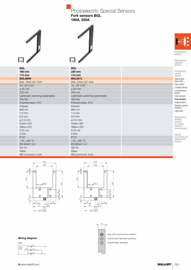
323■ www.balluff.com
BGL BGL
180 mm 220 mm
114 mm 114 mm
BGL000N BGL0014
BGL 180A-007-S49 BGL 220A-007-S4910...30 V DC 10...30 V DC≤ 35 mA ≤ 35 mA200 mA 200 mALight/dark switching (selectable) Light/dark switching (selectable)Yes/Yes Yes/YesPotentiometer, 270° Potentiometer, 270°Infrared Infrared880 nm 880 nm1.5 mm 1.5 mm0.2 mm 0.2 mm≤ 0.5 mm ≤ 0.5 mmGreen LED Green LEDYellow LED Yellow LED0.25 ms 0.25 ms2 kHz 2 kHzIP 67 IP 67–10...+60 °C –10...+60 °CEN 60947-5-2 EN 60947-5-2GD-Zn GD-ZnGlass GlassM8 connector, 3-pin M8 connector, 3-pin
PNP
Potentiometer light/dark switching
Potentiometer, sensitivity
Plug, LED output function indicator
10
Photoelectric Special SensorsFork sensors BGL
180A, 220A
Wiring diagram
Photoelectric sensors
Photoelectric standard sensors
Photoelectric special sensors
Optical fiber base units
Fiber optics
Contrast sensor
Luminescence sensor
Color sensors
Fork sensors
Angle sensors
Dynamic optical windows
Light grids
Photoelectric distance sensors for analog distance measurement
Special accessories for photoelectric sensors

For more information, visit us online!324
Series BGL
Fork opening 30 mm
Fork depth 34 mm
PNP NO/NC Ordering code BGL0019
Part number BGL 30A-003-S49PNPTransparency detection
NO/NC Ordering code
Part numberSupply voltage UB 10...30 V DCNo-load supply current I0 max. ≤ 20 mAOutput current 200 mASwitching type Light/dark switching (selectable)Polarity reversal/short-circuit protected Yes/YesSettings Potentiometer, 270°Emitter, light type Laser, red lightWavelength 650 nmLaser class 1Resolution (smallest discernible part) 50 μmRepeat accuracy 10 μmSwitching hysteresis 20 µmOutput function indicator Yellow LEDResponse time 0.1 msSwitching frequency 5 kHzDegree of protection as per IEC 60529 IP 67Ambient temperature Ta –10...+60 °CAmbient light limit according to EN 60947-5-2Material Housing GD-Zn
Optical surface GlassConnection M8 connector, 3-pin
Connector orientation
Photoelectric Special SensorsFork sensors BGL
30A, 50A
Fork SensorsLaser
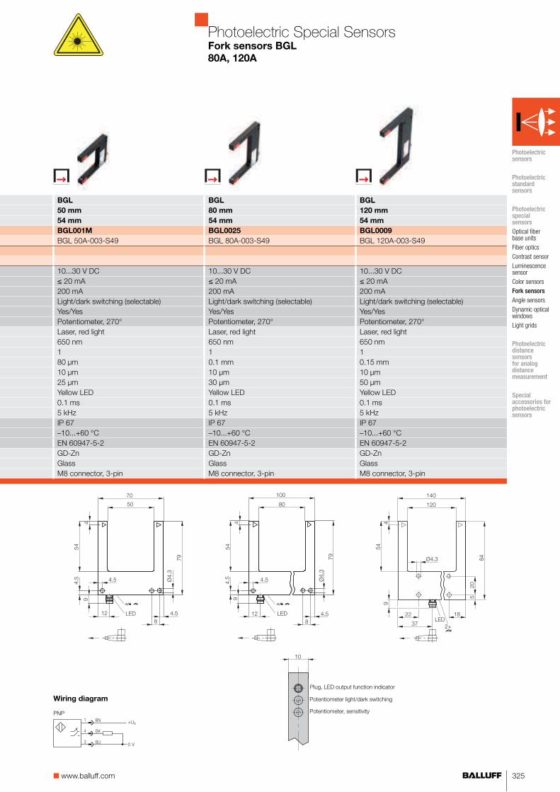
325■ www.balluff.com
BGL BGL BGL
50 mm 80 mm 120 mm
54 mm 54 mm 54 mm
BGL001M BGL0025 BGL0009
BGL 50A-003-S49 BGL 80A-003-S49 BGL 120A-003-S49
10...30 V DC 10...30 V DC 10...30 V DC≤ 20 mA ≤ 20 mA ≤ 20 mA200 mA 200 mA 200 mALight/dark switching (selectable) Light/dark switching (selectable) Light/dark switching (selectable)Yes/Yes Yes/Yes Yes/YesPotentiometer, 270° Potentiometer, 270° Potentiometer, 270°Laser, red light Laser, red light Laser, red light650 nm 650 nm 650 nm1 1 180 μm 0.1 mm 0.15 mm10 μm 10 μm 10 μm25 µm 30 µm 50 µmYellow LED Yellow LED Yellow LED0.1 ms 0.1 ms 0.1 ms5 kHz 5 kHz 5 kHzIP 67 IP 67 IP 67–10...+60 °C –10...+60 °C –10...+60 °CEN 60947-5-2 EN 60947-5-2 EN 60947-5-2GD-Zn GD-Zn GD-ZnGlass Glass GlassM8 connector, 3-pin M8 connector, 3-pin M8 connector, 3-pin
PNP
Potentiometer light/dark switching
Potentiometer, sensitivity
Plug, LED output function indicator
10
Photoelectric Special SensorsFork sensors BGL
80A, 120A
Wiring diagram
Photoelectric sensors
Photoelectric standard sensors
Photoelectric special sensors
Optical fiber base units
Fiber optics
Contrast sensor
Luminescence sensor
Color sensors
Fork sensors
Angle sensors
Dynamic optical windows
Light grids
Photoelectric distance sensors for analog distance measurement
Special accessories for photoelectric sensors

326 For more information, visit us online!
Series BGL BGL
Fork opening 30 mm 30 mm
Fork depth 34 mm 34 mm
PNPTransparency detection
NO/NC Ordering code
Part numberPNPFluid detection
NO/NC Ordering code BGL003J
Part number BGL 30A-011-S49PNPDSC (Dynamic Sensor Control)
NO/NC Ordering code BGL003N
Part number BGL 30A-013-S49Supply voltage UB 10...30 V DC 10...30 V DCNo-load supply current I0 max. ≤ 35 mA ≤ 35 mAOutput current 200 mA 200 mASwitching type Light/dark switching (selectable) Light/dark switching (selectable)Polarity reversal/short-circuit protected Yes/Yes Yes/YesSettings Potentiometer, 270° Potentiometer, 270°Emitter, light type Infrared InfraredWavelength 1480 nm 880 nmResolution (smallest discernible part) 0.6 mm 0.8 mmRepeat accuracy 0.1 mm 0.1 mmSwitching hysteresis ≤ 0.2 mm ≤ 0.3 mmPower-on indicator Green LED Green LEDOutput function indicator Yellow LED Yellow LEDResponse time 0.25 ms 2.5 msSwitching frequency 2 kHz 200 HzDegree of protection as per IEC 60529 IP 67 IP 67Ambient temperature Ta –10...+60 °C –10...+60 °CAmbient light limit according to EN 60947-5-2 EN 60947-5-2Material Housing GD-Zn GD-Zn
Optical surface Glass GlassConnection M8 connector, 3-pin M8 connector, 3-pin
Connector orientation
Fork SensorsSpecial
Photoelectric Special SensorsFork sensors BGL
30 A
Suitable connector
(please order separately)
More electrical accessories: You can find a large selection of plug con-nectors and connector cables in a wide variety of cable materials, colors and lengths in our Industrial Networking and Connectivity catalog.
Mechanical accessories: You can find a large selection of mounting compo-nents of all types, such as clamping holders, mounting brackets and the Balluff mounting system BMS, in our Accessory Product Line catalog.
Size Design Cable
material
Color Length Ordering
code
M8, 3-pin Straight PUR Black 2 m BCC02M8
M8, 3-pin Straight PVC Gray 2 m BCC02NU
M8, 3-pin Angled PUR Black 2 m BCC02ML
M8, 3-pin Angled PVC Gray 2 m BCC02P5
Connectors without LED are suitable for PNP and NPN sensors.

327■ www.balluff.com
BGL BGL BGL BGL
50 mm 80 mm 80 mm 80 mm
54 mm 54 mm 54 mm 54 mm
BGL002T
BGL 80A-009-S49BGL003L
BGL 80A-011-S49BGL003P BGL003R
BGL 50A-013-S49 BGL 80A-013-S4910...30 V DC 10...30 V DC 10...30 V DC 10...30 V DC≤ 35 mA ≤ 35 mA ≤ 35 mA ≤ 20 mA200 mA 200 mA 200 mA 200 mALight/dark switching (selectable) Light/dark switching (selectable) Light/dark switching (selectable) Light/dark switching (selectable)Yes/Yes Yes/Yes Yes/Yes Yes/YesPotentiometer, 270° Potentiometer, 270° Potentiometer, 270° Potentiometer, 270°Infrared Infrared Infrared Laser, red light880 nm 1480 nm 880 nm 650 nm1 mm 0.8 mm 1.2 mm 50 μm0.12 mm 0.1 mm 0.15 mm 10 μm≤ 0.3 mm ≤ 0.2 mm ≤ 0.4 mm 30 µmGreen LED Green LED Green LEDYellow LED Yellow LED Yellow LED Yellow LED0.25 ms 0.25 ms 2.5 ms 0.1 ms200 Hz 2 kHz 200 Hz 5 kHzIP 67 IP 67 IP 67 IP 67–10...+60 °C –10...+60 °C –10...+60 °C –10...+60 °CEN 60947-5-2 EN 60947-5-2 EN 60947-5-2 EN 60947-5-2GD-Zn GD-Zn GD-Zn GD-ZnGlass Glass Glass GlassM8 connector, 3-pin M8 connector, 3-pin M8 connector, 3-pin M8 connector, 3-pin
PNP Potentiometer light/dark switching
Potentiometer, sensitivity
Plug, LED output function indicator
10
Photoelectric Special SensorsFork sensors BGL
50A, 80A
Wiring diagram
Photoelectric sensors
Photoelectric standard sensors
Photoelectric special sensors
Optical fiber base units
Fiber optics
Contrast sensor
Luminescence sensor
Color sensors
Fork sensors
Angle sensors
Dynamic optical windows
Light grids
Photoelectric distance sensors for analog distance measurement
Special accessories for photoelectric sensors

328 For more information, visit us online!
The fork sensor BGL 21 is a photoelectric sensor using a microcon-troller for the setup process and function monitoring. All the user needs to do is press a button to access all the data needed for con-figuring the sensor. An adjustment aid on the top and bottom of the sensor specifies the object position during configuration. The internal microcontroller monitors all settings to ensure optimum switching frequency, repeat accuracy and rejection of optical interference and ambient light. The BGL 21-RG has a red and green emitter diode, which is ideal for detecting colored markings on transparent backing material. Which color of emitter light is more appropriate for the particular task is automatically determined during setup.The BGL 21-IR model with an infrared emitter makes it possible to scan labels or holes on backing material.
Photoelectric Special SensorsFork sensors BGL 21
Fork Sensorsfor Label Sensing
Wiring diagram
Suitable connector
(please order separately)
More electrical accessories: You can find a large selection of plug con-nectors and connector cables in a wide variety of cable materials, colors and lengths in our Industrial Networking and Connectivity catalog.
Size Design Cable
material
Color Length Ordering
code
M8, 4-pin Straight PUR Black 2 m BCC02N2
M8, 4-pin Straight PVC Gray 2 m BCC02PL
M8, 4-pin Angled PUR Black 2 m BCC02NC
M8, 4-pin Angled PVC Gray 2 m BCC02PZ
Connectors without LED are suitable for PNP and NPN sensors.
olor Length Ordering
Features
■ Fast, fully automatic sensor calibration■ User interface has just one button and two LEDs■ Very short response time and high repeat accuracy■ Very resistant to optical interference and ambient light■ NPN/PNP output on separate pins with overload protection■ M8 connector block can be rotated 90°■ Metal housing
Applications
■ Detecting markings on backing material■ Label detection■ Monitoring web tracking■ Web break monitoring■ Hole checking in thin materials (< 2 mm)

329■ www.balluff.com
Series BGL BGL
Fork opening 2 mm 2 mm
Fork depth 50 mm 50 mm
PNP/NPN NC/NO Ordering code BGL002L BGL002M
Part number BGL 21-IR BGL 21-RGSupply voltage UB 10...30 V DC 10...30 V DCNo-load supply current I0 max. ≤ 55 mA ≤ 55 mAOutput current 100 mA 100 mASwitching type Light/dark switching (selectable) Light/dark switching (selectable)Polarity reversal/short-circuit protected Yes/Yes Yes/YesSettings Teach-in Teach-inEmitter, light type Infrared Red and green lightWavelength 880 nm 636 nm/536 nmResolution (smallest discernible part) 1 mm 0.5 mmRepeat accuracy 80 μm 80 μmSwitching hysteresis ≤ 0.2 mm ≤ 0.2 mmOutput function indicator Yellow LED Yellow LEDPower/error indicator Green/red LED Green/red LEDResponse time 20 µs 20 µsSwitching frequency 25 kHz 25 kHzDegree of protection as per IEC 60529 IP 65 IP 65Ambient temperature Ta –20...+60 °C –20...+60 °CAmbient light limit according to EN 60947-5-2 EN 60947-5-2Material Housing Anodized aluminum Anodized aluminum
Optical surface Glass GlassConnection M8 connector, 4-pin M8 connector, 4-pin
Connector orientation
Photoelectric Special SensorsFork sensors BGL 21
Photoelectric sensors
Photoelectric standard sensors
Photoelectric special sensors
Optical fiber base units
Fiber optics
Contrast sensor
Luminescence sensor
Color sensors
Fork sensors
Angle sensors
Dynamic optical windows
Light grids
Photoelectric distance sensors for analog distance measurement
Special accessories for photoelectric sensors

330 For more information, visit us online!
Analog Fork Sensors
Photoelectric Special SensorsAnalog fork sensors BGL_C
In-process correction
Thanks to their band of light, analog fork sensors not only detect objects with absolute reliability, they determine the positions of the objects with extreme precision as well. This makes readjustment in an ongoing process a snap. Process reliability and product quality increase significantly – and more efficiency is a welcome side effect.
Technical highlights
■ Analog signal proportional to the skin depth of the object■ Constant value, even in the event of height variations■ High degree of soiling resistance and compensation■ Fieldbus connection with IO-Link■ Ideal for web edge control
Integral air rinsing nozzle to prevent dust from accumulat-ing on the emitter and receiver optics. Simple connection via standard pneumatic system.

331■ www.balluff.com
Photoelectric Special SensorsAnalog fork sensors BGL_C
Product overview
Type Fork
opening
Resolu-
tion
Light
type
Output Switch-
ing type
Switch-
ing fre-
quency
US Connec-
tion
Page
Red
light
0–10
V
4-20
mA
1× P
NP
tran
sist
or
2× P
NP
tran
sist
or
DSC
(Dyn
amic
Sen
sor
Con
trol
)
Ligh
t sw
itchi
ng
Dar
k sw
itchi
ng
18...
30 V
DC
M12
plu
g, 4
-pin
Fork sensors
BGL002Z BGL 30C-001-S4 30 mm 80 μm ■ ■ ■ ■ 500 Hz ■ ■ 332
BGL0031 BGL 30C-003-S4 30 mm 80 μm ■ ■ ■ ■ ■ 500 Hz ■ ■ 332
BGL0033 BGL 30C-005-S4 30 mm 80 μm ■ ■ ■ ■ ■ 500 Hz ■ ■ 333
BGL0036 BGL 30C-009-S4 30 mm 80 μm ■ ■ ■ ■ ■ 500 Hz ■ ■ 332
BGL0037 BGL 50C-001-S4 50 mm 80 μm ■ ■ ■ ■ 500 Hz ■ ■ 333
BGL0039 BGL 50C-003-S4 50 mm 80 μm ■ ■ ■ ■ ■ 500 Hz ■ ■ 333
BGL003C BGL 50C-005-S4 50 mm 80 μm ■ ■ ■ ■ ■ 500 Hz ■ ■ 333
BGL003H BGL 50C-009-S4 50 mm 80 μm ■ ■ ■ ■ ■ 500 Hz ■ ■ 333
NPN on request
Also available with IO-Link
■ Ordering code
■ Part number
Photoelectric sensors
Photoelectric standard sensors
Photoelectric special sensors
Optical fiber base units
Fiber optics
Contrast sensor
Luminescence sensor
Color sensors
Fork sensors
Angle sensors
Dynamic optical windows
Light grids
Photoelectric distance sensors for analog distance measurement
Special accessories for photoelectric sensors

332 For more information, visit us online!
Series BGL BGL
Fork opening 30 mm 30 mm
Fork depth 54 mm 54 mm
PNP 2 switching outputs NC/NO Ordering code BGL002Z
Part number BGL 30C-001-S4PNP 1 analog and
1 switching/error outputNC/NO Ordering code BGL0031
Part number BGL 30C-003-S4PNP 2 switching outputs
with DSCNC/NO Ordering code BGL0036
Part number BGL 30C-009-S4Supply voltage UB 18...30 V DC 18...30 V DCNo-load supply current I0 max. ≤ 20 mA ≤ 20 mAOutput current 100 mA 100 mAAnalog output 4...20 mASwitching type Light/dark switching (selectable) Light/dark switching (selectable)Polarity reversal/short-circuit protected Yes/Yes Yes/YesSettings Teach-in Teach-inEmitter, light type Red light Red lightWavelength 633 nm 633 nmResolution (smallest discernible part) ≤ 80 μm ≤ 80 μmRepeat accuracy 0.15 mm 0.15 mmSwitching hysteresis < 0.4 mm < 0.4 mmOutput function indicator 2× Yellow LEDs 2× Yellow LEDsResponse time 2 ms 2 msSwitching frequency 500 Hz 500 HzMeasurement field length 28 mm 28 mmDegree of protection as per IEC 60529 IP 65 IP 65Ambient temperature Ta –5...+55°C –5...+55°CAmbient light limit according to EN 60947-5-2 EN 60947-5-2Material Housing Anodized aluminum Anodized aluminum
Optical surface PMMA PMMAConnection M12 connector, 4-pin M12 connector, 4-pin
Photoelectric Special SensorsAnalog fork sensors BGL_C
30C
80
35
3.5
93.5
28
65
35
17
6
17
43
5
108.5
Ø5.2
54
80
35
3.5
93.5
28
65
35
17
6
17
43
5
108.5
Ø5.2
54
Analog Fork Sensors
18
80
M12x1
Light/dark switching teach-in
Sensitivity teach-in
Output 1 LED output function indicator
Output 2 LED output function indicator
Suitable connector
(please order separately)
More electrical accessories: You can find a large selection of plug con-nectors and connector cables in a wide variety of cable materials, colors and lengths in our Industrial Networking and Connectivity catalog.
Size Design Cable
material
Color Length Ordering
code
M12, 4-pin Straight PUR Black 2 m BCC032F
M12, 4-pin Straight PVC Gray 2 m BCC0367
M12, 4-pin Angled PUR Black 2 m BCC032Y
M12, 4-pin Angled PVC Gray 2 m BCC036N
Connectors without LED are suitable for PNP and NPN sensors.

333■ www.balluff.com
BGL BGL BGL BGL
30 mm 50 mm 50 mm 50 mm
54 mm 54 mm 54 mm 54 mm
BGL0037
BGL 50C-001-S4BGL0033 BGL0039 BGL003C
BGL 30C-005-S4 BGL 50C-003-S4 BGL 50C-005-S4BGL003H
BGL 50C-009-S418...30 V DC 18...30 V DC 18...30 V DC 18...30 V DC≤ 20 mA ≤ 20 mA ≤ 20 mA ≤ 20 mA100 mA 100 mA 100 mA 100 mA0...10 V DC 4...20 mA 0...10 V DCLight/dark switching (selectable) Light/dark switching (selectable) Light/dark switching (selectable) Light/dark switching (selectable)Yes/Yes Yes/Yes Yes/Yes Yes/YesTeach-in Teach-in Teach-in Teach-inRed light Red light Red light Red light633 nm 633 nm 633 nm 633 nm≤ 80 μm ≤ 80 μm ≤ 80 μm ≤ 80 μm0.15 mm 0.15 mm 0.15 mm 0.15 mm< 0.4 mm < 0.4 mm < 0.4 mm < 0.4 mm2× Yellow LEDs 2× Yellow LEDs 2× Yellow LEDs 2× Yellow LEDs2 ms 2 ms 2 ms 2 ms500 Hz 500 Hz 500 Hz 500 Hz28 mm 28 mm 28 mm 28 mmIP 65 IP 65 IP 65 IP 65–5...+55°C –5...+55°C –5...+55°C –5...+55°CEN 60947-5-2 EN 60947-5-2 EN 60947-5-2 EN 60947-5-2Anodized aluminum Anodized aluminum Anodized aluminum Anodized aluminumPMMA PMMA PMMA PMMAM12 connector, 4-pin M12 connector, 4-pin M12 connector, 4-pin M12 connector, 4-pin
Photoelectric Special SensorsAnalog fork sensors BGL_C
30C, 50C
80
35
3.5
93.5
28
65
35
17
6
17
43
5
108.5
Ø5.2
54
100
85
35
3,5
28
93.5
54
17
63
35
5
10
17
6
Ø5.2
8.5
100
85
35
3,5
28
93.5
54
17
63
35
5
10
17
6
Ø5.2
8.5
100
85
35
3,5
28
93.5
54
17
63
35
5
10
17
6
Ø5.2
8.5
Wiring diagrams
Out 1
Out 2
DSC
Out
Out/Error
A
Out/Error
V
BGL... 001-S4 BGL... 003-S4
BGL... 009-S4 BGL... 005-S4
Photoelectric sensors
Photoelectric standard sensors
Photoelectric special sensors
Optical fiber base units
Fiber optics
Contrast sensor
Luminescence sensor
Color sensors
Fork sensors
Angle sensors
Dynamic optical windows
Light grids
Photoelectric distance sensors for analog distance measurement
Special accessories for photoelectric sensors

334 For more information, visit us online!
Angle Sensors
Angle sensors are needed whenever space is too tight for fork sen-sors and you can no longer find a (simple) solution for applications. This is due to the fact that, with nearly identical specifications, the design of the Balluff angle sensors BWL Standard can be used to find a solution for even more applications. The design and beam geometry allow objects to be approached and scanned from almost any direction, while red light and laser variants ensure versatile use.
Applications
■ Assembly and handling technology ■ Robotic systems ■ Position and location control
Benefits
■ High accuracy■ Visible light spot for easy alignment■ Can be installed even in tight mounting conditions
The Balluff angle sensor BWL Automotive is a powerful photoelec-tric sensor designed for harsh industrial use. Its housing is tough and allows for variable mounting options.Objects are reliably detected, even under extremely difficult condi-tions.A strong infrared emitter ensures a large function reserve and various designs allow for flexible use, allowing the creation of elegant solu-tions for a vast number of applications.
Applications
■ Robotic systems ■ Position and location control
Photoelectric Special SensorsAngle sensors BWL

335■ www.balluff.com
Photoelectric Special SensorsAngle sensors BWL
Product overview
Type Optical axis Resolu-
tion
Light type Output Switching
type
Switch-
ing fre-
quency
US Connec-
tion
Page
Infr
ared
Red
ligh
t
Red
ligh
t, pi
n po
int
Lase
r
PN
P t
rans
isto
r
Ligh
t sw
itchi
ng
Dar
k sw
itchi
ng
10
...3
0 V
DC
M8
plu
g, 3
-pin
M1
2 c
onne
ctor
, 4-p
in
Angle sensors
Standard
BWL000F BWL 4040D-R011-S49 40/40 mm 0.4 mm ■ ■ ■ ■ 1.5 kHz ■ ■ 336
BWL000J BWL 4040D-R013-S49 40/40 mm 0.3 mm ■ ■ ■ ■ 5 kHz ■ ■ 338
BWL000C BWL 4040D-L011-S49 40/40 mm 80 μm ■ ■ ■ ■ 5 kHz ■ ■ 342
BWL0009 BWL 4040D-I011-S49 40/40 mm 1.0 mm ■ ■ ■ ■ 2 kHz ■ ■ 340
BWL000R BWL 5454D-R011-S49 54/54 mm 0.4 mm ■ ■ ■ ■ 1.5 kHz ■ ■ 336
BWL000U BWL 5454D-R013-S49 54/54 mm 0.4 mm ■ ■ ■ ■ 5 kHz ■ ■ 338
BWL000N BWL 5454D-L011-S49 54/54 mm 100 μm ■ ■ ■ ■ 5 kHz ■ ■ 342
BWL000L BWL 5454D-I011-S49 54/54 mm 1.2 mm ■ ■ ■ ■ 2 kHz ■ ■ 340
BWL0012 BWL 6868D-R011-S49 68/68 mm 0.5 mm ■ ■ ■ ■ 1.5 kHz ■ ■ 337
BWL001N BWL 6868D-R013-S49 68/68 mm 0.4 mm ■ ■ ■ ■ 5 kHz ■ ■ 339
BWL0010 BWL 6868D-L011-S49 68/68 mm 120 μm ■ ■ ■ ■ 5 kHz ■ ■ 343
BWL000Y BWL 6868D-I011-S49 68/68 mm 1.5 mm ■ ■ ■ ■ 2 kHz ■ ■ 341
BWL0019 BWL 9090D-R011-S49 90/90 mm 0.6 mm ■ ■ ■ ■ 1.5 kHz ■ ■ 337
BWL001C BWL 9090D-R013-S49 90/90 mm 0.5 mm ■ ■ ■ ■ 5 kHz ■ ■ 339
BWL0017 BWL 9090D-L011-S49 90/90 mm 150 μm ■ ■ ■ ■ 5 kHz ■ ■ 343
BWL0015 BWL 9090D-I011-S49 90/90 mm 1.5 mm ■ ■ ■ ■ 1 kHz ■ ■ 341
BWL0005 BWL 110110D-R011-S49 110/110 mm 0.6 mm ■ ■ ■ ■ 1.5 kHz ■ ■ 337
BWL0007 BWL 110110D-R013-S49 110/110 mm 0.6 mm ■ ■ ■ ■ 5 kHz ■ ■ 339
BWL0003 BWL 110110D-L011-S49 110/110 mm 0.2 mm ■ ■ ■ ■ 5 kHz ■ ■ 343
BWL0001 BWL 110110D-I011-S49 110/110 mm 1.5 mm ■ ■ ■ ■ 2 kHz ■ ■ 341
Angle sensors
Automotive
BWL001F BWL 2222B-001-S4 22/22 mm ■ ■ ■ 1 kHz ■ ■ 344
BWL001H BWL 2222C-001-S4 22/22 mm ■ ■ ■ 1 kHz ■ ■ 344
BWL001J BWL 4241A-001-S4 43/43 mm ■ ■ ■ 1 kHz ■ ■ 345
BWL001K BWL 4241A-001-S49 43/43 mm ■ ■ ■ 1 kHz ■ ■ 345
BWL001L BWL 4260A-001-S4 42/62 mm ■ ■ ■ 1 kHz ■ ■ 345
BWL001M BWL 4260A-001-S49 42/62 mm ■ ■ ■ 1 kHz ■ ■ 345
NPN on request
■ Ordering code
■ Part number
Photoelectric sensors
Photoelectric standard sensors
Photoelectric special sensors
Optical fiber base units
Fiber optics
Contrast sensor
Luminescence sensor
Color sensors
Fork sensors
Angle sensors
Dynamic optical windows
Light grids
Photoelectric distance sensors for analog distance measurement
Special accessories for photoelectric sensors

For more information, visit us online!336
Series BWL BWL
Optical axis 40/40 mm 54/54
PNP NO/NC Ordering code BWL000F BWL000R
Part number BWL 4040D-R011-S49 BWL 5454D-R011-S49Supply voltage UB 10...30 V DC 10...30 V DCNo-load supply current I0 max. ≤ 35 mA ≤ 35 mAOutput current 200 mA 200 mASwitching type Light/dark switching (selectable) Light/dark switching (selectable)Polarity reversal/short-circuit protected Yes/Yes Yes/YesSettings Potentiometer, 270° Potentiometer, 270°Emitter, light type LED, red light LED, red lightWavelength 640 nm 640 nmResolution (smallest discernible part) 0.4 mm 0.4 mmRepeat accuracy 40 μm 60 μmSwitching hysteresis ≤ 0.15 mm ≤ 0.2 mmOutput function indicator Yellow LED Yellow LEDResponse time 0.33 ms 0.33 msSwitching frequency 1.5 kHz 1.5 kHzDegree of protection as per IEC 60529 IP 67 IP 67Ambient temperature Ta –10...+60 °C –10...+60 °CAmbient light limit according to EN 60947-5-2 EN 60947-5-2Material Housing GD-Zn GD-Zn
Optical surface Glass GlassConnection M8 connector, 3-pin M8 connector, 3-pin
Connector orientation
Photoelectric Special SensorsAngle sensors BWL
40/40 mm, 54/54 mm
Angle SensorsRed light

337■ www.balluff.com
BWL BWL BWL
68/68 mm 90/90 mm 110/110 mm
BWL0012 BWL0019 BWL0005
BWL 6868D-R011-S49 BWL 9090D-R011-S49 BWL 110110D-R011-S4910...30 V DC 10...30 V DC 10...30 V DC≤ 35 mA ≤ 35 mA ≤ 35 mA200 mA 200 mA 200 mALight/dark switching (selectable) Light/dark switching (selectable) Light/dark switching (selectable)Yes/Yes Yes/Yes Yes/YesPotentiometer, 270° Potentiometer, 270° Potentiometer, 270°LED, red light LED, red light LED, red light640 nm 640 nm 640 nm0.5 mm 0.6 mm 0.6 mm80 μm 80 μm 80 μm≤ 0.2 mm ≤ 0.2 mm ≤ 0.2 mmYellow LED Yellow LED Yellow LED0.33 ms 0.33 ms 0.33 ms1.5 kHz 1.5 kHz 1.5 kHzIP 67 IP 67 IP 67–10...+60 °C –10...+60 °C –10...+60 °CEN 60947-5-2 EN 60947-5-2 EN 60947-5-2GD-Zn GD-Zn GD-ZnGlass Glass GlassM8 connector, 3-pin M8 connector, 3-pin M8 connector, 3-pin
Wiring diagram
PNPPotentiometer light/dark switching
Plug, LED output function indicator
10
Potentiometer, sensitivity
Photoelectric Special SensorsAngle sensors BWL
68/68 mm, 90/90 mm, 110/110 mm
Photoelectric sensors
Photoelectric standard sensors
Photoelectric special sensors
Optical fiber base units
Fiber optics
Contrast sensor
Luminescence sensor
Color sensors
Fork sensors
Angle sensors
Dynamic optical windows
Light grids
Photoelectric distance sensors for analog distance measurement
Special accessories for photoelectric sensors

For more information, visit us online!338
Series BWL BWL
Optical axis 40/40 mm 54/54
PNP NO/NC Ordering code BWL000J BWL000U
Part number BWL 4040D-R013-S49 BWL 5454D-R013-S49Supply voltage UB 10...30 V DC 10...30 V DCNo-load supply current I0 max. ≤ 35 mA ≤ 35 mAOutput current 200 mA 200 mASwitching type Light/dark switching (selectable) Light/dark switching (selectable)Polarity reversal/short-circuit protected Yes/Yes Yes/YesSettings Potentiometer, 270° Potentiometer, 270°Emitter, light type Red light, pin point Red light, pin pointWavelength 640 nm 640 nmResolution (smallest discernible part) 0.3 mm 0.4 mmRepeat accuracy 30 μm 40 μmSwitching hysteresis ≤ 0.1 mm ≤ 0.15 mmOutput function indicator Yellow LED Yellow LEDResponse time 0.1 ms 0.1 msSwitching frequency 5 kHz 5 kHzDegree of protection as per IEC 60529 IP 67 IP 67Ambient temperature Ta –10...+60 °C –10...+60 °CAmbient light limit according to EN 60947-5-2 EN 60947-5-2Material Housing GD-Zn GD-Zn
Optical surface Glass GlassConnection M8 connector, 3-pin M8 connector, 3-pin
Connector orientation
Photoelectric Special SensorsAngle sensors BWL
40/40 mm, 54/54 mm
Angle SensorsPin Point

339■ www.balluff.com
BWL BWL BWL
68/68 mm 90/90 mm 110/110 mm
BWL001N BWL001C BWL0007
BWL 6868D-R013-S49 BWL 9090D-R013-S49 BWL 110110D-R013-S4910...30 V DC 10...30 V DC 10...30 V DC≤ 35 mA ≤ 35 mA ≤ 35 mA200 mA 200 mA 200 mALight/dark switching (selectable) Light/dark switching (selectable) Light/dark switching (selectable)Yes/Yes Yes/Yes Yes/YesPotentiometer, 270° Potentiometer, 270° Potentiometer, 270°Red light, pin point Red light, pin point Red light, pin point640 nm 640 nm 640 nm0.4 mm 0.5 mm 0.6 mm40 μm 50 μm 60 μm≤ 0.15 mm ≤ 0.15 mm ≤ 0.2 mmYellow LED Yellow LED Yellow LED0.1 ms 0.1 ms 0.1 ms5 kHz 5 kHz 5 kHzIP 67 IP 67 IP 67–10...+60 °C –10...+60 °C –10...+60 °CEN 60947-5-2 EN 60947-5-2 EN 60947-5-2GD-Zn GD-Zn GD-ZnGlass Glass GlassM8 connector, 3-pin M8 connector, 3-pin M8 connector, 3-pin
Photoelectric Special SensorsAngle sensors BWL
68/68 mm, 90/90 mm, 110/110 mm
Wiring diagram
PNPPotentiometer light/dark switching
Plug, LED output function indicator
10
Potentiometer, sensitivity
Photoelectric sensors
Photoelectric standard sensors
Photoelectric special sensors
Optical fiber base units
Fiber optics
Contrast sensor
Luminescence sensor
Color sensors
Fork sensors
Angle sensors
Dynamic optical windows
Light grids
Photoelectric distance sensors for analog distance measurement
Special accessories for photoelectric sensors

For more information, visit us online!340
Series BWL BWL
Optical axis 40/40 mm 54/54
PNP NO/NC Ordering code BWL0009 BWL000L
Part number BWL 4040D-I011-S49 BWL 5454D-I011-S49Supply voltage UB 10...30 V DC 10...30 V DCNo-load supply current I0 max. ≤ 35 mA ≤ 35 mAOutput current 200 mA 200 mASwitching type Light/dark switching (selectable) Light/dark switching (selectable)Polarity reversal/short-circuit protected Yes/Yes Yes/YesSettings Potentiometer, 270° Potentiometer, 270°Emitter, light type Infrared InfraredWavelength 880 nm 880 nmResolution (smallest discernible part) 1 mm 1.2 mmRepeat accuracy 0.12 mm 0.15 mmSwitching hysteresis ≤ 0.3 mm ≤ 0.4 mmOperating function indicator Green LED Green LEDOutput function indicator Yellow LED Yellow LEDResponse time 0.25 ms 0.25 msSwitching frequency 2 kHz 2 kHzDegree of protection as per IEC 60529 IP 67 IP 67Ambient temperature Ta –10...+60 °C –10...+60 °CAmbient light limit according to EN 60947-5-2 EN 60947-5-2Material Housing GD-Zn GD-Zn
Optical surface Glass GlassConnection M8 connector, 3-pin M8 connector, 3-pin
Connector orientation
60+0.2
Photoelectric Special SensorsAngle sensors BWL
40/40 mm, 54/54 mm
Angle SensorsInfrared
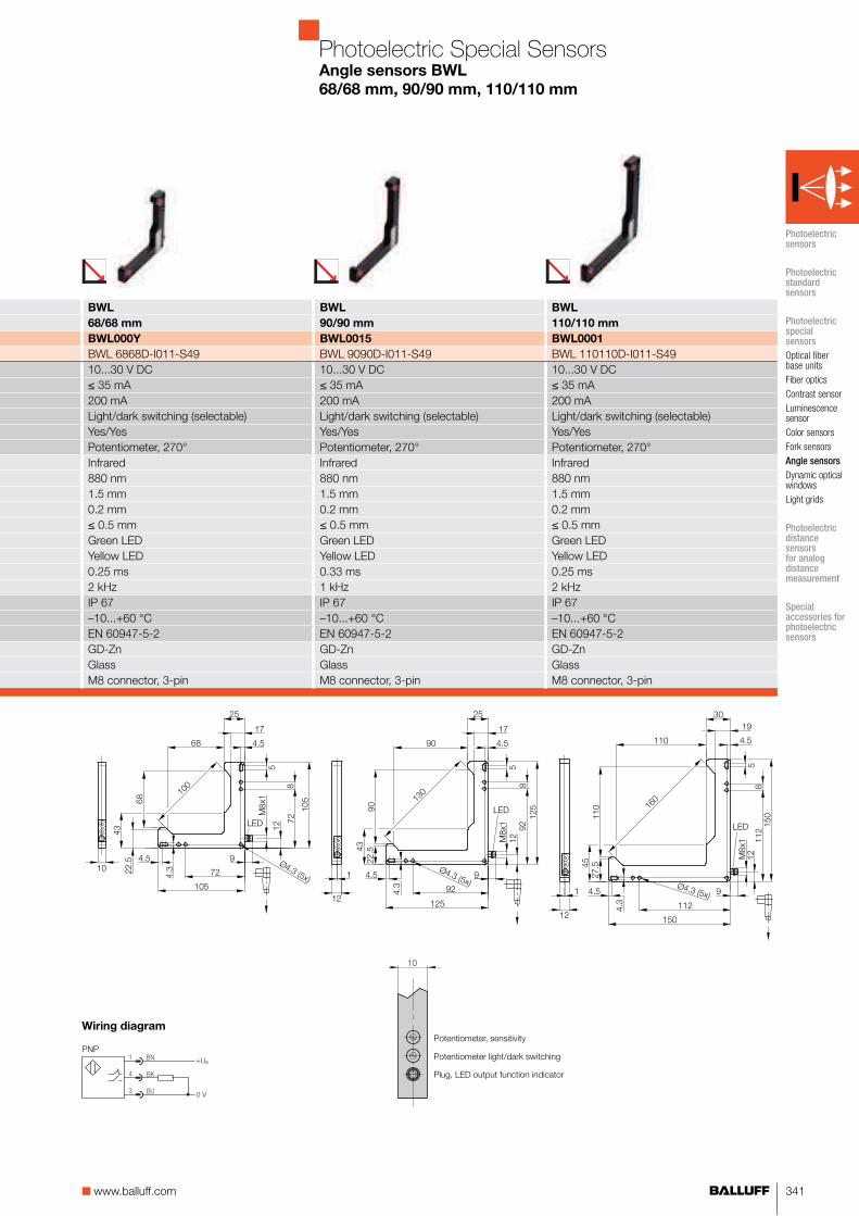
341■ www.balluff.com
BWL BWL BWL
68/68 mm 90/90 mm 110/110 mm
BWL000Y BWL0015 BWL0001
BWL 6868D-I011-S49 BWL 9090D-I011-S49 BWL 110110D-I011-S4910...30 V DC 10...30 V DC 10...30 V DC≤ 35 mA ≤ 35 mA ≤ 35 mA200 mA 200 mA 200 mALight/dark switching (selectable) Light/dark switching (selectable) Light/dark switching (selectable)Yes/Yes Yes/Yes Yes/YesPotentiometer, 270° Potentiometer, 270° Potentiometer, 270°Infrared Infrared Infrared880 nm 880 nm 880 nm1.5 mm 1.5 mm 1.5 mm0.2 mm 0.2 mm 0.2 mm≤ 0.5 mm ≤ 0.5 mm ≤ 0.5 mmGreen LED Green LED Green LEDYellow LED Yellow LED Yellow LED0.25 ms 0.33 ms 0.25 ms2 kHz 1 kHz 2 kHzIP 67 IP 67 IP 67–10...+60 °C –10...+60 °C –10...+60 °CEN 60947-5-2 EN 60947-5-2 EN 60947-5-2GD-Zn GD-Zn GD-ZnGlass Glass GlassM8 connector, 3-pin M8 connector, 3-pin M8 connector, 3-pin
Photoelectric Special SensorsAngle sensors BWL
68/68 mm, 90/90 mm, 110/110 mm
Wiring diagram
PNPPotentiometer light/dark switching
Plug, LED output function indicator
10
Potentiometer, sensitivity
Photoelectric sensors
Photoelectric standard sensors
Photoelectric special sensors
Optical fiber base units
Fiber optics
Contrast sensor
Luminescence sensor
Color sensors
Fork sensors
Angle sensors
Dynamic optical windows
Light grids
Photoelectric distance sensors for analog distance measurement
Special accessories for photoelectric sensors

For more information, visit us online!342
Series BWL BWL
Optical axis 40/40 mm 54/54 mm
PNP NO/NC Ordering code BWL000C BWL000N
Part number BWL 4040D-L011-S49 BWL 5454D-L011-S49Supply voltage UB 10...30 V DC 10...30 V DCNo-load supply current I0 max. ≤ 20 mA ≤ 20 mAOutput current 200 mA 200 mASwitching type Light/dark switching (selectable) Light/dark switching (selectable)Polarity reversal/short-circuit protected Yes/Yes Yes/YesSettings Potentiometer, 270° Potentiometer, 270°Emitter, light type Laser, red light LaserWavelength 640 nm 640 nmLaser class 1 1Resolution (smallest discernible part) 80 μm 100 μmRepeat accuracy ≤ 10 μm 10 μmSwitching hysteresis ≤ 25 μm ≤ 35 μmOutput function indicator Yellow LED Yellow LEDResponse time 0.1 ms 0.1 msSwitching frequency 5 kHz 5 kHzDegree of protection as per IEC 60529 IP 67 IP 67Ambient temperature Ta –10...+60 °C –10...+60 °CAmbient light limit according to EN 60947-5-2 EN 60947-5-2Material Housing GD-Zn GD-Zn
Optical surface Glass GlassConnection M8 connector, 3-pin M8 connector, 3-pin
Connector orientation
Photoelectric Special SensorsAngle sensors BWL
40/40 mm, 54/54 mm
Angle SensorsLaser
Suitable connector
(please order separately)
More electrical accessories: You can find a large selection of plug con-nectors and connector cables in a wide variety of cable materials, colors and lengths in our Industrial Networking and Connectivity catalog.
Size Design Cable
material
Color Length Ordering
code
M8, 3-pin Straight PUR Black 2 m BCC02M8
M8, 3-pin Straight PVC Gray 2 m BCC02NU
M8, 3-pin Angled PUR Black 2 m BCC02ML
M8, 3-pin Angled PVC Gray 2 m BCC02P5
Connectors without LED are suitable for PNP and NPN sensors.

343■ www.balluff.com
Potentiometer light/dark switching
Plug, LED output function indicator
10
Potentiometer, sensitivity
BWL BWL BWL
68/68 mm 90/90 mm 110/110 mm
BWL0010 BWL0017 BWL0003
BWL 6868D-L011-S49 BWL 9090D-L011-S49 BWL 110110D-L011-S4910...30 V DC 10...30 V DC 10...30 V DC≤ 20 mA ≤ 20 mA ≤ 20 mA200 mA 200 mA 200 mALight/dark switching (selectable) Light/dark switching (selectable) Light/dark switching (selectable)Yes/Yes Yes/Yes Yes/YesPotentiometer, 270° Potentiometer, 270° Potentiometer, 270°Laser Laser Laser640 nm 640 nm 640 nm1 1 1120 μm 150 μm 0.2 mm≤ 15 μm ≤ 15 μm ≤ 20 μm≤ 40 μm ≤ 50 μm ≤ 70 μmYellow LED Yellow LED Yellow LED0.1 ms 0.1 ms 0.1 ms5 kHz 5 kHz 5 kHzIP 67 IP 67 IP 67–10...+60 °C –10...+60 °C –10...+60 °CEN 60947-5-2 EN 60947-5-2 EN 60947-5-2GD-Zn GD-Zn GD-ZnGlass Glass GlassM8 connector, 3-pin M8 connector, 3-pin M8 connector, 3-pin
Photoelectric Special SensorsAngle sensors BWL
68/68 mm, 90/90 mm, 110/110 mm
Wiring diagram
PNP
Photoelectric sensors
Photoelectric standard sensors
Photoelectric special sensors
Optical fiber base units
Fiber optics
Contrast sensor
Luminescence sensor
Color sensors
Fork sensors
Angle sensors
Dynamic optical windows
Light grids
Photoelectric distance sensors for analog distance measurement
Special accessories for photoelectric sensors

344 For more information, visit us online!
Series BWL BWL
Optical axis 22/22 mm 22/22 mm
PNP NO/NC Ordering code BWL001F BWL001H
Part number BWL 2222B-001-S4 BWL 2222C-001-S4Supply voltage UB 10...30 V DC 10...30 V DCNo-load supply current I0 max. ≤ 35 mA ≤ 35 mAOutput current ≤ 200 mA ≤ 200 mASwitching type Dark switching Dark switchingPolarity reversal/short-circuit protected Yes/Yes Yes/YesEmitter, light type Infrared InfraredWavelength 880 nm 880 nmPower-on indicator Green LED Green LEDOutput function indicator Yellow LED Yellow LEDReady delay 100 ms 100 msResponse time ≤ 0.5 ms ≤ 0.5 msSwitching frequency 1 kHz 1 kHzDegree of protection as per IEC 60529 IP 67 IP 67Ambient temperature Ta –10...+60 °C –10...+60 °CAmbient light limit according to EN 60947-5-2 EN 60947-5-2Material Housing Corrosion-resistant steel Corrosion-resistant steel
Optical surface PMMA PMMAConnection M12 connector, 4-pin M12 connector, 4-pin
Connector orientation
Photoelectric Special SensorsAngle sensors BWL
22/22 mm
Angle SensorsAutomotive
Suitable connector
(please order separately)
More electrical accessories: You can find a large selection of plug con-nectors and connector cables in a wide variety of cable materials, colors and lengths in our Industrial Networking and Connectivity catalog.
Size Design Cable
material
Color Length Ordering
code
M8, 3-pin Straight PUR Black 2 m BCC02M8
M8, 3-pin Straight PVC Gray 2 m BCC02NU
M8, 3-pin Angled PUR Black 2 m BCC02ML
M8, 3-pin Angled PVC Gray 2 m BCC02P5
Connectors without LED are suitable for PNP and NPN sensors.
Suitable connector
(please order separately)
More electrical accessories: You can find a large selection of plug con-nectors and connector cables in a wide variety of cable materials, colors and lengths in our Industrial Networking and Connectivity catalog.
Size Design Cable
material
Color Length Ordering
code
M12, 4-pin Straight PUR Black 2 m BCC032F
M12, 4-pin Straight PVC Gray 2 m BCC0367
M12, 4-pin Angled PUR Black 2 m BCC032Y
M12, 4-pin Angled PVC Gray 2 m BCC036N
Connectors without LED are suitable for PNP and NPN sensors.

345■ www.balluff.com
BWL BWL BWL BWL
43/43 mm 43/43 mm 42/62 mm 42/62 mm
BWL001J BWL001K BWL001L BWL001M
BWL 4241A-001-S4 BWL 4241A-001-S49 BWL 4260A-001-S4 BWL 4260A-001-S4910...30 V DC 10...30 V DC 10...30 V DC 10...30 V DC≤ 35 mA ≤ 35 mA ≤ 35 mA ≤ 35 mA≤ 200 mA ≤ 200 mA ≤ 200 mA ≤ 200 mADark switching Dark switching Dark switching Dark switchingYes/Yes Yes/Yes Yes/Yes Yes/YesInfrared Infrared Infrared Infrared880 nm 880 nm 880 nm 880 nmGreen LED Green LED Green LED Green LEDYellow LED Yellow LED Yellow LED Yellow LED100 ms 100 ms 100 ms 100 ms≤ 0.5 ms ≤ 0.5 ms ≤ 0.5 ms ≤ 0.5 ms1 kHz 1 kHz 1 kHz 1 kHzIP 67 IP 67 IP 67 IP 67–10...+60 °C –10...+60 °C –10...+60 °C –10...+60 °CEN 60947-5-2 EN 60947-5-2 EN 60947-5-2 EN 60947-5-2Corrosion-resistant steel Corrosion-resistant steel Corrosion-resistant steel Corrosion-resistant steelPMMA PMMA PMMA PMMAM12 connector, 4-pin M8 connector, 3-pin M12 connector, 4-pin M8 connector, 3-pin
Photoelectric Special SensorsAngle sensors BWL
43/43 mm, 42/62 mm
Wiring diagrams
PNP
Photoelectric sensors
Photoelectric standard sensors
Photoelectric special sensors
Optical fiber base units
Fiber optics
Contrast sensor
Luminescence sensor
Color sensors
Fork sensors
Angle sensors
Dynamic optical windows
Light grids
Photoelectric distance sensors for analog distance measurement
Special accessories for photoelectric sensors

346 For more information, visit us online!
Dynamic Optical Window
The ideal use for dynamic optical windows BOW is when objects do not just have to be scanned in some places, but throughout an entire area (window) instead. Thanks to their multitude of beams arranged in parallel, they can detect objects in a broad window. A constant, high resolution is ensured at each location in the window in the process. BOW sensors are dynamic, which means that parts are detected in the active area when they are moving.
Photoelectric Special SensorsDynamic optical windows BOW
Features
■ Constant, high resolution ■ Dynamic operation■ Only moving objects are detected, so feed trays and the like
do not affect the measurement■ Detects small parts down to 1 mm■ Adjustable output signal length■ Adjustable sensitivity■ Three window sizes■ Standard M8 connector
Applications
■ Compressed air feeding of small parts■ Thread break monitoring■ Eject monitoring■ Counting/separating parts

347■ www.balluff.com
Photoelectric Special Sensors Dynamic optical windows BOW
Product overview
■ Ordering code
■ Part number
Type Active
area
Resolution Light type Output Switching
type
Principle US Connec-
tion
Page
Infr
ared
PN
P t
rans
isto
r
Dar
k sw
itchi
ng
Dyn
amic
10
...3
0 V
DC
M8
plu
g, 3
-pin
Dynamic
optical windows
BOW001A BOW A-0408-PS-C-S49 40×80 mm 1 mm ■ ■ ■ ■ ■ ■ 348
BOW001J BOW A-0808-PS-C-S49 80×80 mm 1 mm ■ ■ ■ ■ ■ ■ 349
BOW0012 BOW A-1208-PS-C-S49 120×80 mm 1.2 mm ■ ■ ■ ■ ■ ■ 349
Photoelectric sensors
Photoelectric standard sensors
Photoelectric special sensors
Optical fiber base units
Fiber optics
Contrast sensor
Luminescence sensor
Color sensors
Fork sensors
Angle sensors
Dynamic opti-cal windows
Light grids
Photoelectric distance sensors for analog distance measurement
Special accessories for photoelectric sensors

348 For more information, visit us online!
Series BOW
Active area 40×80 mm
PNP NC/NO Ordering code BOW001A
Part number BOW A-0408-PS-C-S49Supply voltage UB 10...30 V DCNo-load supply current I0 max. ≤ 40 mAOutput current 200 mASwitching type Dark switchingPolarity reversal/short-circuit protected Yes/YesSettings 2× Potentiometer, 270°Emitter, light type LED, infraredWavelength 880 nmResolution (smallest discernible part) 1.0 mmPower-on indicator Green LEDOutput function indicator Red LEDTurn-on delay 0.2 msSignal duration for pulse stretching 10...300 ms adjustableSwitching frequency 3...100 Hz dyn.Degree of protection as per IEC 60529 IP 67Ambient temperature Ta –10...+55 °CAmbient light limit according to EN 60947-5-2Material Housing Anodized aluminum
Optical surface PMMAConnection M8 connector, 3-pin
Photoelectric Special SensorsDynamic optical windows BOW
40×80 mm
40
8
17
25
M8x1
80
20
30
6
5.5
Ø9
10.5
4x Ø4.3
Dynamic Optical Window
Suitable connector
(please order separately)
More electrical accessories: You can find a large selection of plug con-nectors and connector cables in a wide variety of cable materials, colors and lengths in our Industrial Networking and Connectivity catalog.
Size Design Cable
material
Color Length Ordering
code
M8, 3-pin Straight PUR Black 2 m BCC02M8
M8, 3-pin Straight PVC Gray 2 m BCC02NU
M8, 3-pin Angled PUR Black 2 m BCC02ML
M8, 3-pin Angled PVC Gray 2 m BCC02P5
Connectors without LED are suitable for PNP and NPN sensors.

349■ www.balluff.com
BOW BOW
80×80 mm 120×80 mm
BOW001J BOW0012
BOW A-0808-PS-C-S49 BOW A-1208-PS-C-S4910...30 V DC 10...30 V DC≤ 45 mA ≤ 60 mA200 mA 200 mADark switching Dark switchingYes/Yes Yes/Yes2× Potentiometer, 270° 2× Potentiometer, 270°LED, infrared LED, infrared880 nm 880 nm1.0 mm 1.2 mmGreen LED Green LEDRed LED Red LED0.2 ms 0.2 ms10...300 ms adjustable 10...300 ms adjustable3...100 Hz dyn. 3...100 Hz dynIP 67 IP 67–10...+55 °C –10...+55 °CEN 60947-5-2 EN 60947-5-2Anodized aluminum Anodized aluminumPMMA PMMAM8 connector, 3-pin M8 connector, 3-pin
Photoelectric Special SensorsDynamic optical windows BOW
80×80 mm, 120×80 mm
Note when using for ambient light: The receiver is located on the connector side.
Wiring diagram
8
17
25
M8x1
10.5
10
5.5
80
20
30
6
2x M6x1
4x Ø4.3
80
60
Ø9
M8x1
25
17
8
120
100
5.5
Ø9
80
10
20
30
2x M6x16
10.5
4x Ø4.3
Supply voltage LED
Output signal LED
Signal duration potentiometerPotentiometer, sensitivity
Connector
18
Photoelectric sensors
Photoelectric standard sensors
Photoelectric special sensors
Optical fiber base units
Fiber optics
Contrast sensor
Luminescence sensor
Color sensors
Fork sensors
Angle sensors
Dynamic opti-cal windows
Light grids
Photoelectric distance sensors for analog distance measurement
Special accessories for photoelectric sensors

350 For more information, visit us online!
Light Grids
Light grids BGL are normally used for reliably detecting wide and very large objects. BGL sensors are available in various measure-ment field heights of 100, 150 and 300 mm and allow both large and small ranges. Light grids with a measurement field height of 100 and 150 mm can be ordered with low or high resolution.The light grid can be simply and quickly installed using the supplied mounting bracket. Setup and installation are user friendly and easy to accomplish.The system features an analog voltage output for outputting the height or width of an object directly. An additional switching output indicates whether the object is within the monitored range.
Photoelectric Special SensorsLight grids BLG
Features
■ Easy to connect ■ Easy to install ■ Ready for operation immediately ■ No cumbersome configuration of parameters ■ Ranges 150 mm...2.1 m■ Measurement field heights 100, 150, 300 mm■ Analog output
Applications
■ Counting parts ■ Height measurement and height checking ■ Presence verification ■ Slack and position checking ■ Pallet checking ■ Web monitoring ■ Position and material monitoring

351■ www.balluff.com
Photoelectric Special SensorsLight grids BLG
Product overview
■ Ordering code
■ Part number
Type Measuring
field
height
Range Resolution Light type Output Switching
type
US Connec-
tion
Page
0.1
5..
.2.1
m
5 m
m
7 m
m
Infr
ared
PN
P t
rans
isto
r
Ana
log
0..
.10
V
Dar
k sw
itchi
ng
24
V D
C
M1
2 p
lug
Light grids
BLG0001 BLG 1-010-210-050-PV01-SX 100 mm ■ ■ ■ ■ ■ ■ ■ ■ 353
BLG0002 BLG 1-010-210-070-PV01-SX 100 mm ■ ■ ■ ■ ■ ■ ■ ■ 353
BLG0003 BLG 1-015-210-050-PV01-SX 150 mm ■ ■ ■ ■ ■ ■ ■ ■ 353
BLG0004 BLG 1-015-210-070-PV01-SX 150 mm ■ ■ ■ ■ ■ ■ ■ ■ 353
BLG0005 BLG 1-030-210-070-PV01-SX 300 mm ■ ■ ■ ■ ■ ■ ■ ■ 353
Photoelectric sensors
Photoelectric standard sensors
Photoelectric special sensors
Optical fiber base units
Fiber optics
Contrast sensor
Luminescence sensor
Color sensors
Fork sensors
Angle sensors
Dynamic optical windows
Light grids
Photoelectric distance sensors for analog distance measurement
Special accessories for photoelectric sensors

352 For more information, visit us online!
SeriesMeasurement field heightPNP NO Resolution 5 mm Ordering code
Part numberPNP NO Resolution 7 mm Ordering code
Part numberSupply voltage UB
No-load supply current I0 max. EmitterReceiver
Output currentSwitching typeShort-circuit protectedAnalog outputSettingsEmitter, light typeWavelengthPower-on indicator Emitter/ReceiverOutput function indicatorDegree of protection as per IEC 60529Ambient temperature Ta
Material HousingOptical surface
Connection EmitterReceiver
Photoelectric Special SensorsLight grids BLG
Number of covered beams
Analog output
Wiring diagrams
Emitter Receiver
Resolution diagram
Range 0.15...2.1 m
Range (D) mm
Min
. res
olut
ion
(R) m
m
20001700700 1300300 10000 18001400400 1500500 1100150 800 210019001600600 1200200 900
12
10
8
6
2
4
0
Standard resolution
High resolution
Recommended accessories
(please order separately)
You can find special accessories for diffuse sensors, such as reflectors, apertures, lenses, filters and deflection heads, in this catalog starting on page 379.
More mechanical accessories: You can find a large selection of mounting components of all types, such as clamping holders, mounting brackets and the Balluff mounting system BMS, in our Accessory Product Line catalog.
Light Grids
Mounting bracket
(included)
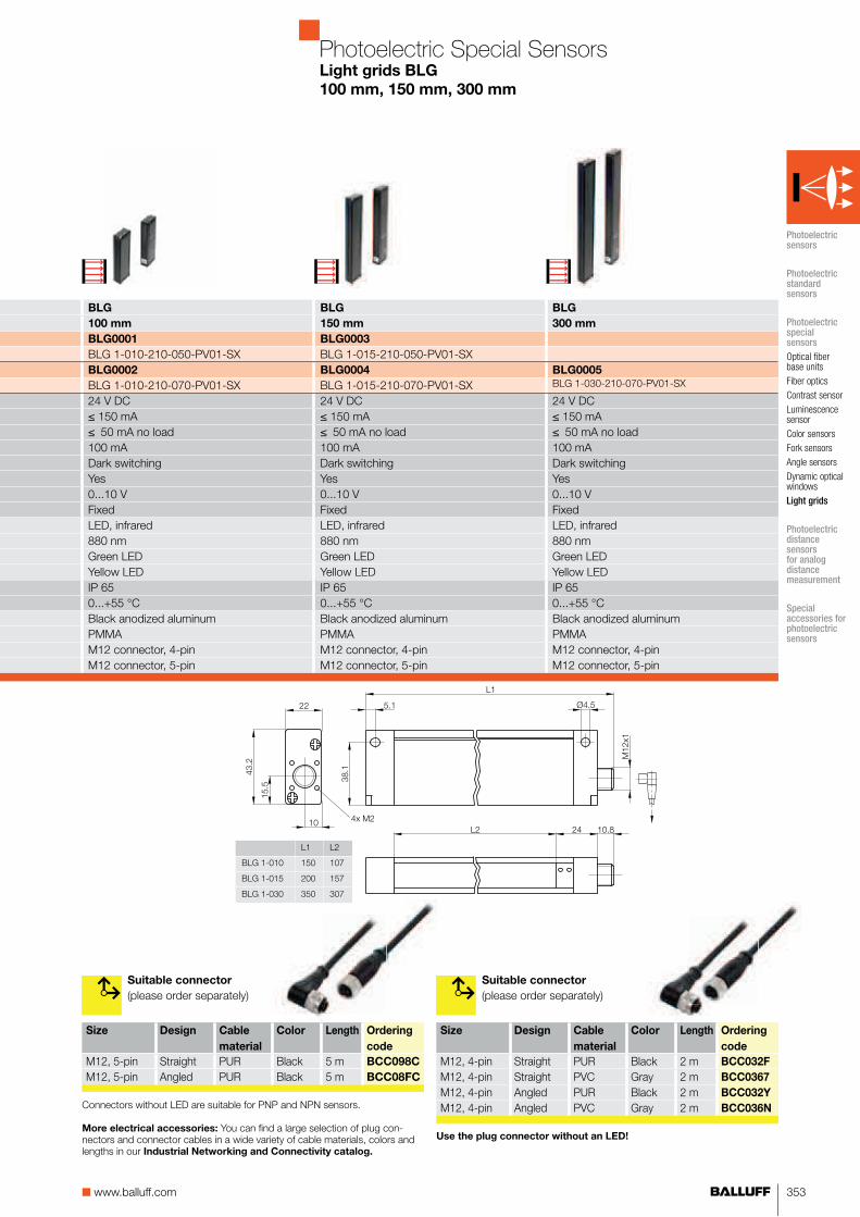
353■ www.balluff.com
BLG BLG BLG
100 mm 150 mm 300 mm
BLG0001 BLG0003
BLG 1-010-210-050-PV01-SX BLG 1-015-210-050-PV01-SXBLG0002 BLG0004 BLG0005
BLG 1-010-210-070-PV01-SX BLG 1-015-210-070-PV01-SX BLG 1-030-210-070-PV01-SX
24 V DC 24 V DC 24 V DC≤ 150 mA ≤ 150 mA ≤ 150 mA≤ 50 mA no load ≤ 50 mA no load ≤ 50 mA no load100 mA 100 mA 100 mADark switching Dark switching Dark switchingYes Yes Yes0...10 V 0...10 V 0...10 VFixed Fixed FixedLED, infrared LED, infrared LED, infrared880 nm 880 nm 880 nmGreen LED Green LED Green LEDYellow LED Yellow LED Yellow LEDIP 65 IP 65 IP 650...+55 °C 0...+55 °C 0...+55 °CBlack anodized aluminum Black anodized aluminum Black anodized aluminumPMMA PMMA PMMAM12 connector, 4-pin M12 connector, 4-pin M12 connector, 4-pinM12 connector, 5-pin M12 connector, 5-pin M12 connector, 5-pin
Photoelectric Special SensorsLight grids BLG
100 mm, 150 mm, 300 mm
L1 L2
BLG 1-010 150 107
BLG 1-015 200 157
BLG 1-030 350 307
Suitable connector
(please order separately)
Size Design Cable
material
Color Length Ordering
code
M12, 4-pin Straight PUR Black 2 m BCC032F
M12, 4-pin Straight PVC Gray 2 m BCC0367
M12, 4-pin Angled PUR Black 2 m BCC032Y
M12, 4-pin Angled PVC Gray 2 m BCC036N
Use the plug connector without an LED!
Suitable connector
(please order separately)
More electrical accessories: You can find a large selection of plug con-nectors and connector cables in a wide variety of cable materials, colors and lengths in our Industrial Networking and Connectivity catalog.
Size Design Cable
material
Color Length Ordering
code
M12, 5-pin Straight PUR Black 5 m BCC098C
M12, 5-pin Angled PUR Black 5 m BCC08FC
Connectors without LED are suitable for PNP and NPN sensors.
Photoelectric sensors
Photoelectric standard sensors
Photoelectric special sensors
Optical fiber base units
Fiber optics
Contrast sensor
Luminescence sensor
Color sensors
Fork sensors
Angle sensors
Dynamic optical windows
Light grids
Photoelectric distance sensors for analog distance measurement
Special accessories for photoelectric sensors

884 For more information, visit us online!
Basic Information and Definitions

885■ www.balluff.com
Basic Information and DefinitionsContents
General basic information
Electrical 886Mechanical 890Quality 887
Specific basic information
Photoelectric sensors 892Inductive sensors 902Capacitive sensors 916Magnetic cylinder sensors 924

886 For more information, visit us online!
Basic Information and DefinitionsElectric properties
Smallest bending radius
Special cable
Cable types
The SP- cable is a irradiated cross-linked PUR- cable that has good resistance to weld splatter. A special connection cable is used for sensors that need to be used at higher ambient temperatures.
The permitted tightening torque is indicated in the data sheets or on the sensor packaging.
Tightening torques
PUR cable, PUR insulated
PVC cable, PVC insulated
tensioned untensioned drag chain and
roll deflection
4×D 3×D 4×D...7.5×D only with "SP" wire
No. of wires × conductor
cross-section
Outside diameter
typical
2×0.14 mm² 2.5...3.5 mm2×0.34 mm² 4.5...5.5 mm3×0.14 mm² 2.7...4.5 mm3×0.25 mm² 4...5 mm3×0.34 mm² 4.5...5.5 mm4×0.25 mm² 4.5...5.5 mm
No. of wires ×
conductor cross-section
Outside diameter
typical
2×0.08 mm² 3...4 mm2×0.14 mm² 3...4.1 mm2×0.34 mm² 4...5.5 mm3×0.06 mm² 2...2.5 mm3×0.09 mm² 2.5...3 mm3×0.14 mm² 2.5...3.5 mm3×0.25 mm² 3.5...4.5 mm3×0.34 mm² 4...5.5 mm3×0.75 mm² 6.5...7 mm4×0.14 mm² 3...4 mm4×0.25 mm² 4...5.5 mm8×0.25 mm² 6...8 mm
Cable properties

887■ www.balluff.com
Basic Information and DefinitionsQuality
General basic information
Electrical
Mechanical
Quality
Specific basic information
Quality and the environment
Quality management system
as per DIN EN ISO 9001:2008
Environmental management
system as per
DIN EN ISO 14001:2009
Testing laboratory
Balluff products comply with
EU directives
Product approvals
Balluff companies
Balluff GmbH GermanyBalluff SIE Sensorik GmbH GermanyBalluff Controles Elétricos Ltda. Brazil Balluff Sensors (Chengdu) Co., Ltd. ChinaBalluff Ltd. Great BritainBalluff Automation S.R.L. ItalyBalluff Canada Inc. CanadaBalluff de México S.A. de C.V. MexicoBalluff GmbH AustriaBalluff Sp. z o.o. PolandBalluff Hy-Tech AG SwitzerlandBalluff Sensortechnik AG SwitzerlandBalluff S.L. SpainBalluff CZ, s.r.o Czech RepublicBalluff Elektronika Kft. HungaryBalluff Inc. USA
Product approvals are awarded by domestic and international institu-tions. Their symbols affirm that our products meet the specifications of these institutions.
"US Safety System" and "Canadian Standards Association" under the auspices of Underwriters Laboratories Inc. (cUL).
CCC-Code by the Chinese CQC.
Products that require labeling are subject to a conformity evaluation process according to the EU directive and the product is labeled with the CE marking. Balluff products fall under the following EU directive:
Balluff companies
Balluff GmbH GermanyBalluff Sensors (Chengdu) Co., Ltd. ChinaBalluff Elektronika KFT Hungary
2004/108/EC EMC directive2006/95/EC Low Voltage Directive valid for
products with supply voltage ≥ 75 V DC/≥ 50 V AC
94/9/EC ATEX-directive valid for products with Ex-label
The Balluff testing laboratory operates in accordance with ISO/IEC 17025 and is accredited by DAkks for testing electromagnetic compatibility (EMC).

888 For more information, visit us online!
Basic Information and DefinitionsElectric properties
EMC (Electromagnetic
Compatibility)
Environmental simulation
EX area
Standards
Low-voltage switchgear and controlgear EN 60947-5-2/IEC 60947-5-2NAMUR-sensors EN 60947-5-6/IEC 60947-5-6
Vibration, sinusoidal EN 60068-2-6/IEC 60068-2-6Shock EN 60068-2-27/IEC 60068-2-27Continuous shock EN 60068-2-29/IEC 60068-2-29
Electrical equipment for explosive atmospheres, general requirements.
EN 50014
Succeeded by:Electrical equipment for gas explosive atmospheres, general requirements.
EN 60079-0
Electrical apparatus for explosive areas – intrinsic safety "i".
EN 50020
For conformity, see product marking.
Emissions, RF noise voltage and RF noise radiation from electrical equipment
EN 55011
Interference immunity against discharging static electricity (ESD)
EN 61000-4-2/IEC 61000-4-2
Radio frequency immunity against high-frequency electromagnetic fields (RFI)
EN 61000-4-3/IEC 61000-4-3
Immunity to fast transients (bursts) EN 61000-4-4/IEC 61000-4-4
Interference immunity against conducted interference, induced by high-frequency fields
EN 61000-4-6/IEC 61000-4-6
Immunity to voltage dips and voltage interruptions EN 61000-4-11/IEC 61000-4-11
Surge-voltage stability EN 60947-5-2/IEC 60947-5-2
II # EN 60947-5-2/IEC 60947-5-2
IP 60...67 EN 60529/IEC 60529IP 68 per BWN Pr. 20 Balluff factory standard (BWN): Temperature storage
48 h at 60 °C, 8 temperature cycles according to EN 60068-2-14/IEC 60068-2-14 between the bench-mark temperatures according to the data sheet, 1 h storage in water, insulation inspection, 24 h storage in water, insulation test, 8 temperature cycles ac-cording to EN 60068-2-14 IEC 60068-2-14 between the benchmark temperatures according to the data sheet, 7 days storage in water, insulation test.
P 68 according to BWN Pr. 27 Balluff Factory Standard (BWN): Testing products for use in the foods industry.
IP 69K DIN 40050 part 9: Protection against entry of water under high pressure- or steam jet cleaning.
Sensors
Protection class
Degree of protection

889■ www.balluff.com
Basic Information and DefinitionsElectric properties
Mounting torques
Housing tolerances for un-
threaded cylindrical sensors
Size Material Tightening torque
M5×0.5 Stainless steel 3 NmM8 × 1 Stainless steel 15 NmM12×1 Stainless steel 40 NmM18×1 PBT 1 NmM18×1 Stainless steel 60 NmM30×1.5 PBT 3 NmM30×1.5 Stainless steel 90 Nm
Diameter Tolerance
Ø 3 mm –0.1Ø 4 mm –0.1Ø 6.5 mm –0.15Ø 8 mm –0.15
Degree of protection
The following torques are to be followed so that the sensors are not mechanically destroyed during installation, as long as no other information is indicated on the data sheet or the sensor packaging.
The degrees of protection are given according to IEC 60529.Code letters IP (International Pro-tection) designate protection for electrical equipment against shock hazard, ingress of solid foreign bodies and water.
IP 69K
Protection against ingress of water at high pressure and steam cleaning per DIN 40050 Part 9.
First digit:
2 Protection against penetration of solid bodies larger than 12 mm, shielding from fingers and objects4 Protection against penetration of solid bodies larger than 1 mm, shielding from tools and wires5 Protection against damaging dust deposits, complete contact protection6 Protection against penetration of dust, complete contact protection
Second digit:
0 No special protection4 Protection against water, which is sprayed from all directions against the equipment5 Protection against a stream of water from a nozzle which hits the equipment from all directions7 Protection against water, if the equipment (housing) is temporarily submerged8 Protection against water when submerged for some time
General basic information
Electrical
Mechanical
Quality
Specific basic information

890 For more information, visit us online!
Basic Information and DefinitionsMechanical properties
Material Use and characteristics
PlasticsABS Acrylonitrile-Butadiene-Styrene Impact-resistant, stiff, limited chemical resistance.
Some types flame-retardant. Used for housings.
AES/CP Acrylonitrile-Ethylene-Propylene-Styrene
Impact-resistant, stiff, limited chemical resistance. Used for housings.
EP Epoxy resin Duromer, molded plastic material, highest mechanical strength and temperature resistance. Very good dimensional stability. Cannot be melted.
Epoxy resin - hollow glass spheres Hollow glass spheres can be treated with epoxy resins. They are used for manufacturing converters with low thickness and high pressure rating.
Tetrafluorethylene-perfluorpropylene High temperature resistance up to 180 °C, insulation material for cable.
LCP Liquid Crystalline Polymer High mechanical strength and temperature resistance. Very good chemical resistance. Inherently non-flammable.
PA Polyamide High impact resistance, good chemical resistance.
PA 6, PA 66, PA mod., PA 12 Polyamide Good mechanical strength. Temperature resistance. PA 12 approved for food industry applications.
PA transp. Transparent polyamide Transparent, hard, inflexible. Good chemical resistance.
PBT Polybutylene terephtalate High mechanical strength and temperature resistance. Some types flame-retardant. Good chemical resistance. Good oil resistance.
PC Polycarbonate Clear, hard, elastic and impact resistant. Good temperature resistance. Limited chemical resistance.
PEEK Polyetheretherketone Thermoplastic. Very high strength and temperature resistance. Good chemical resistance. Can be sterilized, good resistance to ionizing radiation.
PEI Polyetherimide High mechanical strength and good temperature resistance. Good chemical resistance even with many solvents. Transparent with amber-yellow inherent color (not pigmented).
PET Polyethylene terephtalate High resistance to breakage, good dimensional stability.Frequently used in the food industry.
PMMA Polymethylmethacrylate Clear, transparent, hard, scratch-resistant, UV-resistant, mainly for optical applications.
POM Polyoxymethylene High impact resistance, good mechanical strength. Good chemical resistance.
Materials

891■ www.balluff.com
Basic Information and DefinitionsMechanical properties
Material Use and characteristics
PlasticsPP Polypropylene Very good electrical properties. Impact resistant, tough, mechanically resilient.
Very low water uptake. Good to very good chemical resistance.
PPE Polyphenylene ether Tough, inflexible, high mechanical strength over a wide temperature range. Good chemical resistance. Good hot water resistance.
PSU Polysulfone High temperature resistance, high impact resistance, good chemical resistance, FDA approved (food grade).
PTFE Polytetrafluoroethylene Best temperature and chemical resistance, FDA approved (food grade).
PUR Polyurethane Elastic, abrasion-resistant, impact-resistant. Good resistance to oils, greases, solvents (used for gaskets and cable jackets).
PVC Polyvinyl chloride Good mechanical strength and chemical resistance (cable).
PVDF Polyvinylidene fluoride Thermoplastic. High mechanical strength and temperature resistance. Good chemical resistance (similar to PTFE).
MetalWrought aluminum alloy Standard-aluminum for machined cutting. Can be anodized.
Used for housings and mounting components.
CuZn Brass Standard-housing material with surface protection.
Stainless steel Excellent corrosion resistance and strength. Quality 1.4034, 1.4104: Standard-material; quality 1.4305, 1.4301: Standard-material for the food industry; quality 1.4401, 1.4404, 1.4571: With increased requirements on chemical resistance at elevated temperatures for the food industry.
GD-Al die-cast aluminum- Low specific gravity. Good strength and resistance. Some types can be anodized.
GD-Zn die-cast zinc- Good resistance and strength. Usually with protective surface coating.
OtherGlass Good chemical resistance and strength. Used primarily in optical applications (lenses,
cover lenses).
Ceramic Very good strength and chemical resistance. Electrically insulating. Excellent temperature resistance.
General basic information
Electrical
Mechanical
Quality
Specific basic information

892 For more information, visit us online!
Basic Information and DefinitionsPhotoelectric sensors
The alarm output at the receiver (PNP open collector – 30 mA) trig-gers a warning signal in the case of functional interruptions, which can be caused by contamination or mechanical de-adjustment. The alarm output is activated if the received signal lies in the alarm range for a defined amount of time.
stable
unstable
stable
Switching threshold
Stability (green LED)
Alarm
Alarm output
For series BOS 18M Teach-in and BOS 65K, the entire product fam-ily, including diffuse and retroreflective sensors, is equipped with an alarm output.
The turn-off delay is the time which the sensor requires for actuation when the target object leaves the sensing zone, at a transmission efficiency factor of 0.5.
Turn-off delay
Receiver
EmitterBeam splitter
Detection- area
LensReflector
Emitter and receiver use a common lens. The emitter light passes through the beam splitter and the lens to the reflector. The reflector bounces the emitter light back to the lens. This gives retroreflective sensors that work with autocollimation a small, round beam profile. Additional benefits: no dead zone for scanning and for the reflec-tor, better small parts detection, and the switching characteristic is independent of the approach direction.
Autocollimation
Dark switching
according to DIN 44030
Light receiver Amplifier Consumer
non-illuminated conducting switched onilluminated not fully modulated switched off
The switching delay is the time which the sensor requires for actua-tion when the target object leaves the sensing zone, at a transmis-sion efficiency factor of 2.
Turn-on delay
A sensor with an analog output does not switch at a particular target distance. Its analog output emits a distance-dependent output signal. The output voltage corresponds to the object location within the sensing range. These systems operate on the same principle as sensors with background suppression. They generate a linear output signal within a certain range (measur-ing range).
Distance sensors
with analog output

893■ www.balluff.com
Basic Information and DefinitionsPhotoelectric sensors
The ambient light is the portion of light that is received by the receiver, but does not originate at the associated emitter.
Ambient light
Through-beam sensors consist of separate emitter- and receiverunits which have to be aligned opposite each other at the two sides of the detection range. A target interrupts the light beam and causes the receiver to switch, regardless of the surface characteristics. In unfavorable conditions (e.g. dust, moisture, oil), you achieve the best results with through-beam sensors. Ranges of up to 50 m can be achieved.
Target
Emitter Receiver
Through-beam sensor
Sensors for color recognition detect objects based on their color. The sensor is calibrated so that it recognizes objects having a certain color. Then, different colored objects do not generate a switching signal.
Color sensing
Polyurethane jacket
■ Temperature T = +85 °C ■ Excellent chemical resistance■ Flexible■ No embrittlement from oils
and cooling emulsions.
Corrugated metal tube,
silicon jacketed
■ Temperature T = +150 °C■ Highly flexible■ Crush-resistant■ Can be sterilized.
Metal jacket
■ Temperature T = +150 °C■ Resistant to hot swarf■ Flexible■ Crush-resistant
Optical conductors are made of glass or plastic with a diameter of as little as 50 µm and bunched in bundles of several hundred individual fibers to form so-called fiber optics. The fiber ends are ground and polished to meet the quality criteria of the optical industry. The individual fibers are coated with a very thin layer of lubricant. This reduces friction against the outer jacket and between the fibers, so that broken fibers are prevented even when the cable is continu-ously flexed. The transmission properties are guaranteed through this over a long span of time.The ends of the bundles are potted with the connection sleeve and the jacket. Balluff fiber optics thus have an IP 67 rating (IP 65 for metal jacket). Moisture and aggressive media cannot hurt either the fibers or the slide coating, so the optical properties remain unaf-fected. This design distributes axial pull forces evenly over all the fibers, and protects the individual fibers from excessive pull loads.
Fiber optics
In order to achieve a smaller light spot, the light beam of the emitter is focused through lenses. Through the focusing and the light spot caused by it, the switch is better suited to recognize small parts and details. Focusing is often used with retroreflective sensors with background suppression, as well as with retroflective sensors.
Focusing
General basic information
Specific basic information
Photoelectric sensors
Inductive sensors
Capacitive sensors
Magnetic cylinder sensors

894 For more information, visit us online!
Basic Information and DefinitionsPhotoelectric sensors
Light switching
according to DIN 44030
Light receiver Amplifier Consumer
Illuminated Fully modulated Switched onNon-illuminated Not fully modulated switched off
The hysteresis is the distance between the switchpoints for a target approaching and then receding from a photoelectric switch.
Hysteresis
Background suppression
(BGA)
Through the background suppression, objects within a set switch-ing distance are detected, without being impeded by the reflective background, and nearly independent of color and surface of the object (object reflection).Background suppression is achieved by cutting the beam from the emitter to the receiver. To do so, it divides the visible field into an active area and the background. In addition, by dividing the receiver into at least two adjacent areas (e. g. by using a dual diode or a PSD- element) and by means of a geometric arrangement (triangula-tion), the actual position of the object within the sensing range can be determined. Through this, the object and the background can be distinguished accurately. Diffuse sensors with background suppres-sion are characterized by low gray value shift and hysteresis.
The standard target photoelectric sensors are referred to as the Kodak-gray card. This is a cardboard sheet whose surface has a defined degree of reflectivity. The side with 90 % reflection deter-mines the range of diffuse sensors, with 18 % reflection to determine the gray value shift.
Kodak gray card
Gray value shift is the switching distance difference when calibrat-ing using different object reflectivities. The sensor is calibrated for a distance using a Kodak-gray card with 90 % reflection. With the Kodak-gray card with 18 % reflection, the distance achieved with it is measured. The difference between these two switchpoints in % is referred to as the gray value shift. The smaller the gray value shift, the more color-independently the sensor operates.
Gray value shift
Fork sensors are through-beam designs in which the emitter and receiver are arranged across from each other in a U-shaped housing. Through the housing type, alignment and electrical connection are simplified. Different ranges are available by selecting different housing configurations. Fork openings of 5...220 mm are possible in various increments. The built-in potentiometer and apertures allow you to adjust the fork sensors easily for detecting parts down to a diameter of 60 µm.
Fork sensor

895■ www.balluff.com
Basic Information and DefinitionsPhotoelectric sensors
Light is used as a sensor medium in many areas of technology and daily life. Used in controllers- and regulation equipment as a sensor medium. Generally a change in the light intensity in an optical beam (between emitter and receiver) caused by a target object is evaluated. Depending on the properties of this object and the characteristics of the optical beam, the light beam is either interrupted or reflected, or even scattered.Predominantly clocked infrared light-LEDs are used as emitters, and phototransistors are used as receivers. The output signal is for the most part independent of the ambient light conditions, since visible light can be easily filtered out.With critical detection procedures, diffuse sensors and -beams can be used with red light-LEDs, because the light beam and the detection point can be measured visually and can be adjusted more easily. For the various usage conditions, Balluff offers three sensor variants: diffuse sensors, retroreflective light sensors, and one-way photoelectric sensors.
Light as a sensor medium
The output leads can be connected to the wrong potential without destroying the sensor. Together with their polarity reversal protection, these sensors are completely protected against miswiring.
Short-circuit protected
Correction factors
(for diffuse sensors)For objects with varying reflection characteristics, the range can be determined by using the correction factors shown. See the adjacent table.
Correction factor Object, surface
1 Paper, white, matte 200 g/m²1.2...1.6 Metal, shiny1.2...1.8 Aluminum, black anodized1 Styrofoam, white0.6 Cotton fabric, white0.5 PVC, gray 0.4 Wood, rough0.3 Cardboard, black, shiny0.1 Cardboard, black, matte
The purpose of laser protection classes is to protect persons from laser radiation by specifying limit values. Based on this, the lasers used are classified according to a scale reflecting the degree of hazard. The calculations and associated limit values relevant for the classification are described in the standard EN 60825-1:2001-11. The grouping is based on a combination of output power and wave-length, taking into account emission duration, number of pulses and angle extension.
Balluff sensors work in the following laser protection classes:Class 1: Not dangerous, no protective measures.Class 2: Low output, lid-closing reflex sufficient for protection.With devices of protection class 2, the eye closes on its own due to the lid closing reflex before it has been open to the beam for too long. Laser warning signs on the device and possibly also on the machine in which a laser is being used are sufficient. Additional pro-tective measures are not required. When using devices of protection classes 1 and 2, no laser safety officer is necessary in the company.
Lasers, laser class
General basic information
Specific basic information
Photoelectric sensors
Inductive sensors
Capacitive sensors
Magnetic cylinder sensors

896 For more information, visit us online!
Basic Information and DefinitionsPhotoelectric sensors
Light transmission by total
reflection
Without the total reflection at boundary layers described above, fiber optics of today's quality would not be feasible. They consist of a cylindrical, light-conducting core and a surrounding thin-wall jacket. The optical density n of the core is greater than that of the jacket. A light beam is always completely reflected at the junction between core and jacket, and can therefore never leave the core in a radial direction. Theoretically, the light is not weakened by these reflections; however, contamination and small defects both in the core material as well as the boundary layer do cause losses (attenuation) and effectively limit the fiber optic length over which reliable information can be transmit-ted.
Emitter/Receiver
Actual beamEmitter-/receiver beam
Standard target 90 % reflective
With diffuse types, the emitter and receiver are integrated into a single housing. The alignment to a detection object is largely uncriti-cal. A target object (e. g. a standard target which is 90 % reflective) bounces a part of the light from its surface back to the receiver. If the standard target reaches the response curve (see image), the output signal changes. The sensing distance depends on the size, shape, color and properties of the reflective object surface. Using a Kodak-gray card with 90 % reflectivity (like white paper), distances of up to 2 m can be obtained.
Photoelectric sensor
To locate invisible marks on objects, so-called luminescent materi-als (contained in special chalks, inks, paints etc.) are used which can only be made visible under ultraviolet (UV) light. The fluorescent materials convert the invisible UV light (short wavelength, here 380 nm) into visible light (between blue 450 nm and dark red 780 nm). This effect is called photoluminescence. The visible light can then be detected as usual by the receiver component of the sensor.
Luminescence
The permitted humidity is 35 to 85 % (not condensed).Permitted humidity
Light refraction Light beams experience a change in direction (interruption) at the border between two optical media with different optical thicknesses
(e.g. glass/air). The degree of interruption depends on the quotients of the optical thicknesses of both media and on the angle of inci-dence ε to the optical axis.
If a light beam travels from a dense medium, n, into a thinner one, n', its course there will show a greater angle ε'. However, above εcrit. (boundary angle at which the broken beam runs parallel to the boundary layer), it again enters the medium with the thickness n; this means that a total reflection is pending.
Total reflection

897■ www.balluff.com
Basic Information and DefinitionsPhotoelectric sensors
When do you need them?
A part of the emitter light in retroreflective systems is reflected directly back to the receiver from target objects with shiny surfaces, e. g. stainless steel, aluminum or tinplate. Simple Retroreflective light sen-sors can therefore not reliably distinguish reflected light from the ob-ject and reflected light. Erroneous readings therefore cannot be ruled out. For this reason, Balluff retroreflective light sensors are alternatively equipped with polarizing filters, 0which, together with a Balluff
reflector, an optically activated prismatic mirror, form a selective barrier against the reflected light from the object, but still allow the reflector light to occur.
Polarizing filters
How do they work?
Light consists of a wide variety of individual beams, which all sinusoidally oscillate on their dispersal axes. Their oscillation levels, however, are independent of one another and can take on any angle position desired (see image).If they meet a polarizing filter (fine line grid), then only the beams oscillating parallel to the grid level are let through, and the verti-cally oscillating ones are entirely deleted. Of all the other oscillation planes, only the portion which consists of parallel components is allowed to pass.
To suppress mirror reflections
Behind the filter, the light only oscillates parallel to the polariza-tion plane. For this light, an additional 90º rotated polarizing filter becomes an impassable barrier.With a 90º rotated polarizing filter in front of both the emitter- and receiver of a retroreflective system, you can therefore prevent the reflected light of a reflecting target object from falsely triggering the signal of the photo-receiver.
For reliable detection of reflective target objects
On the other hand, the light reflected from the triple mirror, with its polarization plane rotated by 90º as described above, is allowed to pass unhindered by this filter.The receiver of a retroreflective system is thereby fully shielded even when a reflecting target object enters the beam, so that the object is still reliably detected.
General basic information
Specific basic information
Photoelectric sensors
Inductive sensors
Capacitive sensors
Magnetic cylinder sensors

898 For more information, visit us online!
Basic Information and DefinitionsPhotoelectric sensors
ReflectorEmitter/Receiver
Target
With retroreflective light sensors, the emitter and the receiver are in a single housing. A reflector on the opposite side of the beam bounces the emitter's light back to the receiver.A target object interrupts the reflected light beam and causes a change in the output signal. With reflective interfaces, it is advisable that the light reflected from the object is to be blanked out with a polarizing filter in front of the receiver optics, in order to prevent pos-sible error signals.
Retroreflective sensor
Diffuse reflection occurs on an uneven and rough surface. It can be illustrated through a wide variety of poorly reflective and differently aligned miniature mirrors. Incidental light is widely "scattered" from such a surface. The reflection losses are higher the darker and more matte finished the surface is. Diffuse sensors, for example, detect diffuse reflecting light from target objects.
Reflection What is it?
Light beams extend to a straight line in free space. Upon striking an object, they are reflected. Depending on the surface composition of the object, one of three types of reflection occurs: total reflection, retroreflection, and diffuse reflection.
The total reflection reaches a highly reflective (mirroring) surface. The angle of incidence is thereby the same as the angle of reflection (eI = eE ). The reflection losses are in the ideal case negligible.
The retroreflection is caused by two mirrors aligned vertically to each other. A light beam is again projected back through double reflection in the same direction. The angle of incidence can thus be altered in a relatively wide range.
The two-dimensional principle of retroreflection described above can be carried over to a spatial system with three mirrors which are oriented at right angles to each other (one corner of a cube standing on its point). A light beam entering this system is totally reflected by all three surfaces and exits parallel to the incident beam. Triple mirrors are called optically active, because they also turn the polarization level of the reflected light beam by 90°. This property first enables a secure recognition of reflective detection objects, together with a polarization filter with retroreflective light sensors.
Reflectors
(optically active triple mirrors)
Each six triple mirrors are to be arranged into a hexagon and ar-ranged in a honeycomb next to each other. Their orientation with respect to the light beam is then totally unproblematic. These are generally made of plastics with high optical density, injected as sheets or pressed into flexible tape.

899■ www.balluff.com
Basic Information and DefinitionsPhotoelectric sensors
Switching distance s The switching distance is the distance between the standard target and the "sensing surface" of the light sensor for causing a signal change (per EN 60947-5-2).
The rated switching distance
is a switching distance- char-acteristic, which does not take into account manufacturing tolerances, sample differences, operating temperatures, supply voltages, etc.
Real switching distance sr The actual switching distance is the switching distance at mea-sured voltage Ue, taking into account the manufacturing toler-ances at an ambient temperature of (T = +23 °C ±0.5).
Usable switching distance su The usable switching dis-tance is the permitted switch-ing distance within fixed voltage- and temperature limits (0.80 sn ≤ su ≤ 1.20 sn).
Blind zone The blind zone is the range between the sensing surface and the minimum switching distance in which a detection object can-not be detected.
Detection range sd The detection range is the area in which the switching distance of a photoelectric sensor to the standard target can be set.
Rated switching distance sn
120 %
Kod
ak-g
ray
card
sn
sr
su
sd
80 %
Blin
d zo
ne
0 %
Sen
sing
sur
face
135 % 100 %
Photoelectric sensors use mainly the following transmission compo-nents:■ Red light LED: visible light, well-suited as an orientation aid and
for sensor adjustment.■ Infrared LED (IR): Invisible beam with high energy.■ Red light laser: Visible light, optimal for detecting small parts and
high ranges due to the physical properties of the laser.
Emitter light
General basic information
Specific basic information
Photoelectric sensors
Inductive sensors
Capacitive sensors
Magnetic cylinder sensors
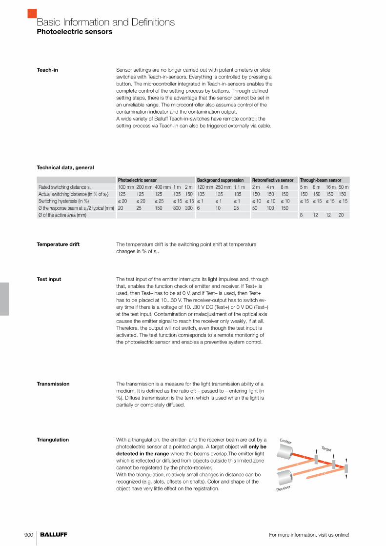
900 For more information, visit us online!
Basic Information and DefinitionsPhotoelectric sensors
Triangulation With a triangulation, the emitter- and the receiver beam are cut by a photoelectric sensor at a pointed angle. A target object will only be
detected in the range where the beams overlap.The emitter light which is reflected or diffused from objects outside this limited zone cannot be registered by the photo-receiver.With the triangulation, relatively small changes in distance can be recognized (e.g. slots, offsets on shafts). Color and shape of the object have very little effect on the registration.
Emitter
Receiver
Target
Sensor settings are no longer carried out with potentiometers or slide switches with Teach-in-sensors. Everything is controlled by pressing a button. The microcontroller integrated in Teach-in-sensors enables the complete control of the setting process by buttons. Through defined setting steps, there is the advantage that the sensor cannot be set in an unreliable range. The microcontroller also assumes control of the contamination indicator and the contamination output.A wide variety of Balluff Teach-in-switches have remote control; the setting process via Teach-in can also be triggered externally via cable.
Teach-in
The temperature drift is the switching point shift at temperature changes in % of sr.
Temperature drift
The test input of the emitter interrupts its light impulses and, through that, enables the function check of emitter and receiver. If Test+ is used, then Test– has to be at 0 V, and if Test– is used, then Test+ has to be placed at 10...30 V. The receiver-output has to switch ev-ery time if there is a voltage of 10...30 V DC (Test+) or 0 V DC (Test–) at the test input. Contamination or maladjustment of the optical axis causes the emitter signal to reach the receiver only weakly, if at all. Therefore, the output will not switch, even though the test input is activated. The test function corresponds to a remote monitoring of the photoelectric sensor and enables a preventive system control.
Test input
The transmission is a measure for the light transmission ability of a medium. It is defined as the ratio of: – passed to – entering light (in %). Diffuse transmission is the term which is used when the light is partially or completely diffused.
Transmission
Photoelectric sensor Background suppression Retroreflective sensor Through-beam sensor
Rated switching distance sn 100 mm 200 mm 400 mm 1 m 2 m 120 mm 250 mm 1.1 m 2 m 4 m 8 m 5 m 8 m 16 m 50 mActual switching distance (in % of sn) 125 125 125 135 150 135 135 135 150 150 150 150 150 150 150Switching hysteresis (in %) ≤ 20 ≤ 20 ≤ 25 ≤ 15 ≤ 15 ≤ 1 ≤ 1 ≤ 1 ≤ 10 ≤ 10 ≤ 10 ≤ 15 ≤ 15 ≤ 15 ≤ 15Ø the response beam at sn/2 typical (mm) 20 25 150 300 300 6 10 25 50 100 150Ø of the active area (mm) 8 12 12 20
Technical data, general

901■ www.balluff.com
Basic Information and DefinitionsPhotoelectric sensors
Output (red LED)
Dar
k-on
Ligh
t-on
stable
unstable
stable
Switching-threshold
Stability (green LED)
The contamination indicator (green) lights in the safe zone if the input energy exceeds the threshold energy by at least 30 %.The threshold energy, at which a signal change affects the output, is defined at 100 %.From this, the safe zone results■ if the input signal exceeds at least 130 % of the
threshold energy■ if the input signal exceeds at least 70 % of the threshold energy.
Contamination indicator
Degree of contamination Pure air Ideal conditions
Trace contamination Relatively clean air in indoor rooms
Slight contamination Workshop- and storage rooms
Moderate contamination Dirty and dusty environments; switching distance is reduced to s = 0.5 su
High contamination Heavy precipitation, whirled-up particles and swarf: Functional failure of the photoelectric sensor is possible.
Highest contamination Coal dust precipitating on the lens. Photoelectric sensor function may fail.
Ambient temperature The ambient temperature is the temperature range in which the function of the photoelectric switch is guaranteed. Balluff Standard: –15 °C ≤ Ta ≤ +55 °C
Contamination (influence on the response range)
Contamination reduces the specified response range of sensors and fiber optics compared to clean air, because the dirt- and dust particles■ deposit on the lenses and
impair their light transmission,■ and absorb and scatter light in the beam path.
An oil-free source of compressed air can be used to prevent the ef-fects of dirt and contamination due to impure air.
The power supply connections can be reversed without destroying the sensor. In combination with the short-circuit protection, there is protection against total reversal.
Polarity reversal protection
General basic information
Specific basic information
Photoelectric sensors
Inductive sensors
Capacitive sensors
Magnetic cylinder sensors

958
Worldwide Sales
Headquarters
GermanyBalluff GmbHSchurwaldstrasse 973765 Neuhausen a.d.F.Phone +49 7158 173-0Fax +49 7158 [email protected]
Subsidiaries and
Representatives
ArgentinaNortécnica S.R.L103 – Heredia 638B1672BKDVilla Lynch – San MartinPcia. de Buenos AiresPhone +54 11 47573129Fax +54 11 [email protected]
AustraliaBalluff-Leuze Pty. Ltd.12 Burton CourtBayswater VIC 3153Phone +61 397 204100Fax +61 397 [email protected]
AustriaBalluff GmbH Industriestrasse B162345 Brunn am GebirgePhone +43 2236 32521-0Fax +43 2236 [email protected]
BelarusAutomaticacentre OOO.Nezavisimosti Av. 185,Block 19, Office 3220125 MinskPhone +375 17 2181713Fax +375 17 [email protected]
BelgiumBalluff bvbaResearchpark Haasrode 1820Interleuvenlaan 62, 3001 LeuvenPhone +32 16 397800Fax +32 16 [email protected]
BrazilBalluff Controles Elétricos Ltda.Rua Francisco Foga, 25Distrito IndustrialCEP 13280.000 Vinhedo – Sao PauloPhone +55 19 38769999Fax +55 19 [email protected]
BulgariaBPS AG41, Nedelcho Bonchev St.1528 SofiaPhone +359 2 9609875Fax +359 2 [email protected]
CanadaBalluff Canada Inc.2840 Argentia Road, Unit 2Mississauga, Ontario L5N 8G4Phone +1 905 816-1494Toll-free 1-800-927-9654Fax +1 905 [email protected]
ChileBalluff ControlesElétricos Ltda.,Brazil
ChinaBalluff (Shanghai) Trading Co. Ltd.Room 1006, Pujian Road 145, Shanghai 200127Phone +86 21 5089 9970Fax +86 21 5089 [email protected]
ColumbiaBalluff ControlesElétricos Ltda.,Brazil
CroatiaHSTEC d.d.Zagrebacka 10023000 ZadarPhone +385 23 205-405Fax +385 23 [email protected]
Czech RepublicBalluff CZ, s.r.oPelušková 1400198 00 Praha 9 – KyjePhone +420 281 000 666Fax +420 281 [email protected]
DenmarkBalluff ApSÅbogade 158200 Århus NPhone +45 70 234929Fax +45 70 [email protected]
EgyptEGEC24 St., 302 Taksym El Kodah-smouha,First Floor, Department 1AlexandriaPhone +20 3 4299771Fax +20 3 [email protected]
FinlandMurri OyKoukkukatu 115700 LahtiPhone +358 3 8824000Fax +358 3 [email protected]
FranceBalluff SASZI Nord de Torcy-Bat 3Rue des Tanneurs – BP 4877201 Marne La Vallée Cedex 1Phone +33 1 64111990Fax +33 1 [email protected]
GreeceS. NAZOS S.A.10 KLM Thessalonikis-KilkisP.O. Box 57008ThessalonikiPhone +30 2310 462120Fax +30 2310 [email protected]
Great Britain and IrelandBalluff Ltd.4 Oakwater AvenueCheadle Royal Business ParkCheadle, Cheshire SK8 3SRPhone +44 161 282-4700Fax +44 161 [email protected]
Hong KongSensortech CompanyNo. 43, 18th StreetHong Lok Yuen,Tai Po, NTPhone +852 26510188Fax +852 [email protected]
HungaryBalluff Elektronika Kft.Pápai út. 55.8200 VeszprémPhone +36 88 421808Fax +36 88 [email protected]
IndiaBalluff India405 Raikar ChambersDeonar Village Road,Govandi, Mumbai 400088Phone +91 22 25568097Fax +91 22 [email protected]
IndonesiaPT. Multiguna CemerlangBumi Serpong Damai Sektor XIMultipurpose Industrial Building Block H 3-31Serpong Tangerang15314 Banten Phone +62 21 75875555 Fax +62 21 [email protected]
IcelandSmith & NorlandNóatúni 4105 ReykjavíkPhone +354 520 3000Fax +354 520 [email protected]
IsraelAncitech Ltd.19, Hamashbir St.Industrial Zone Holon 58853 HolonPhone +972 3 5568351Fax +972 3 [email protected]
ItalyBalluff Automation S.R.L.Via Morandi 410095 Grugliasco, TorinoPhone +39 11 3150711Fax +39 11 [email protected]
JapanBalluff Co., Ltd.Ishikawa Bldg. 2nd Fl.1-5-5 Yanagibashi, Taito-KuTokyo 111-0052Tel. +81 03 5833-5440Fax +81 03 [email protected]
Kazakhstanelcos electric control systems2A, Molodezhniy Str. 3D Block O., Offices 318-319050061 Almaty Phone +7 727 3340536 Fax +7 727 3340539 [email protected]
Latvia and EstoniaSIA InterautomatikaBrīvības g. 4101024 RīgaPhone +371 67522010Fax +371 [email protected]
LithuaniaUAB InterautomatikaKęstučio 4708127 VilniusPhone +370 5 2607810Fax +370 5 [email protected]
MalaysiaProfacto Solution & Services Sdn. Bhd.No. 23-1 Jalan Bandar Empat BalasPusat Bandar Puchong,47100 Puchong, SelangorPhone +60 35882 2684Fax +60 35882 [email protected]
Team Automation Systems (M) Sdn. Bhd.2A, Jalan MP17, Taman Merdeka Permai, Batu Berendam, 75250 MelakaPhone +60 6 3366223Fax +60 6 [email protected]
MexicoBalluff de México S.A. de C.V.Anillo Vial II Fray Junípero Serra No. 4416Colonia La Vista Residencial, CP 76232Delegación Epigmenio GonzálezQueretaro, Qro.Phone +52 442 2124882Fax +52 442 [email protected]
NetherlandsBalluff B.V.Europalaan 6a5232 BC 's-HertogenboschPhone +31 73 6579702Fax +31 73 [email protected]
New Zealand Balluff-Leuze Pty. Ltd.,Australia
NorwayPrimatec asLillesandsveien 444877 GrimstadPhone +47 37 258700Fax +47 37 [email protected]
PhilippinesTechnorand Sales Corporation803 Wilshire Annapolis Plaza,No. 11 Annapolis Street, San Juan, Metro Manila 1500Phone +63 2 7245006Fax +63 2 [email protected]
PolandBalluff Sp. z o.o.Ul. Muchoborska 1654-424 WrocławPhone +48 71 3384929Fax +48 71 [email protected]

959■ www.balluff.com
Worldwide Sales
PortugalLA2P Lda.Rua Teofilo Braga, 156 AEscrit. F – Edificio S. DomingosCabeco Do Mouro2785-122 S. Domingos De RanaPhone +351 21 4447070Fax +351 21 [email protected]
RomaniaEast Electric s.r.l.256 Basarabia Blvd.030352 BucurestiPhone +40 31 4016301Fax +40 31 [email protected]
RussiaBalluff OOOM. Kaluzhskaja Street 15 Building 17, Office 500119071 MoscowTel. +7 495 78071-94Fax +7 495 [email protected]
SerbiaENEL d.o.o.Ul. Vasilja Pavlovica 1014000 ValjevoPhone +381 14 291161Fax +381 14 [email protected]
SingaporeBalluff Asia Pte. Ltd.18 Sin Ming Lane#06-41 Midview City, Singapore 573960Phone +65 62524384Fax +65 [email protected]
SlovakiaBalluff Slovakia s.r.o.Blagoevova 985104 BratislavaPhone +421 2 67200062Fax +421 2 [email protected]
SloveniaSenzorji SB d.o.o.,Proizvodnja, trgovina in storitve d.o.o.Livadna ulica 12204 Miklavž na Dravskem poljuPhone +386 2 6290300Fax +386 2 [email protected]
SpainBalluff S.L.Edificio Forum SCVPlanta 5°, Oficina 4° Carretera Sant Cugat a RubiKm01, 40-5008190 Sant Cugat del VallésBarcelonaPhone +34 93 5441313Fax +34 93 [email protected]
South AfricaPAL Distributers CC291A Pine Avenue, FerndaleRandburg, GautengPhone +27 11 7814381Fax +27 11 [email protected]
South KoreaMahani Electric Co. Ltd.792-7 Yeoksam-DongKangnam-Gu, SeoulPostal code: 135-080Phone +82 2 21943300Fax +82 2 [email protected]
SwedenBalluff ABGamlestadsvägen 2, B1941502 GöteborgPhone +46 31 3408630Fax +46 31 [email protected]
SwitzerlandBalluff Sensortechnik AGRiedstrasse 68953 DietikonPhone +41 43 3223240Fax +41 43 [email protected]
TaiwanCanaan Electric Corp.6F-5, No. 63 Sec. 2 Chang An East Road10455 TaipeiPhone +886 22 5082331Fax +886 22 [email protected]
ThailandCompomax Co. Ltd.16 Soi Ekamai 4, Sukhumvit 63 Rd.Prakanongnua, Vadhana,Bangkok 10110Phone +66 2 7269595Fax +66 2 [email protected]
TurkeyBalluff Sensor OtomasyonSanayi Ve Ticaret Ltd. Sti.Perpa Ticaret Is MerkeziA Blok, Kat 1-2-3No: 0013-001434381 Okmeydani/IstanbulPhone +90 212 3200411 Fax +90 212 [email protected]
UkraineMicronlogistik Ltd.Ul. Promyischlennaya Street 3765031 OdessaPhone +380 48 7781278Fax +380 48 [email protected]
United Arab EmiratesMultiline Technical Co.TCA, behind ADCB Bank46530 Abu DhabiPhone +971 2 6457760Fax +971 2 [email protected]
USABalluff Inc.8125 Holton DriveFlorence, KY 41042-0937Phone +1 859 727-2200,Toll-free 1-800-543-8390Fax +1 859 [email protected]
VenezuelaBalluff Controles Elétricos Ltda., Brazil
VietnamAnh Nghi Son Service Trading Co., Ltd.D3 KDC Mieu Noi Dinh Tien Hoang St., W3, Binh Thanh Dist.,Ho Chi Minh City+84 8 35170401+84 8 [email protected]

960
Selection
Integration
Instruction
Application
Industrial identification
Project support
Vision sensors
IO-Link
Industrial networking
and connectivity
Product
System components
Decision help
Tec
TecSupportYour added value for planning and commissioning

961■ www.balluff.com
We offer ...
■ Decision help for the correct product selection■ Complex product and application support ■ Integration support■ Customer-specific product and commissioning training ■ Intensive technical support during the entire phase of the project ■ Assumption of time-consuming project work
We support you during the project implementation,
commissioning and integration
■ Would you like to monitor and track production processes? ■ Would you like to identify, control, monitor and optimize objects?■ Would you like to optimize and simplify your system wiring?
We provide you with specific support for Balluff system
components
■ Vision sensors BVS for optical identification■ Industrial networking and connectivity for wiring and networking■ IO-Link – network technology for reliable data transfer and greater
efficiency■ Industrial identification – RFID for transparency in material flow
Support
We are happy to help!Phone +49 7158 173-401
+49 7158 173-727
e-Mail [email protected]
TecSupportYour added value for planning and commissioning


963■ www.balluff.com
Customized ServicesAccording to your specifications. In the best quality.
Application advice
through our TecSupport: Discuss your technical require-ments. And take advantage of our expertise.
Real-world examples:■ Selection of the correct identification procedure for an assembly line■ IO-Link concept as a cost-effective alternative to conventional wiring■ System consulting for radio frequency identification (RFID): identification of large steel pipes in
adverse environments■ Recognizing multiple containers on a pallet in goods receiving
Commissioning: Order expert knowledge. And benefit from a quick start of production.
Real-world examples:■ Setting up an optical checkpoint with the BVS vision sensor■ Consulting and support during the programming of BIS RFID systems■ Installation and commissioning of a color detection application with the BFS color sensor
Fully customized products:
Order individual versions ac-cording to your requirements: from preassembly to engineer-ing services. And take advan-tage of the optimum.
Real-world examples:■ Extending the housing of a BHS high-pressure resistant inductive sensor■ Extra threads for the housing cover of a micropulse transducer BTL■ Customer-specific holder for an RFID data carrier ■ Adaptation of the characteristics for analog sensors BAW
Workshops: make use of well-founded manufacturer knowledge. And benefit from application security.
■ Professional sensor use: Select operating principles, install sensors professionally and ensure the reliable operation of your application.
■ Linear position sensing: This is how you measure precisely and wear-free.■ RFID: The right data at the right time at the right place.■ Vision sensor: Using an image processing sensor, ensure manufacturing quality in three steps.■ Vision sensor identification: Reliably identify data matrix codes with
an image-processing sensor. ■ Industrial networking with IO-Link: Manage signals intelligently and cost-effectively.
The right solutions
High application security
Less time required
Significant cost reduction
Balluff offers highly efficient sensor technology with high-perfor-mance mini sensors and compact connection technology. And more. Because with our extensive services, you can obtain support direct from the manufacturer: from the design and planning of your projects, to testing and setup on-site, to training and support. Over the entire life cycle of our products.
This creates greater planning security and provides faster com-missioning and an earlier start of production. This leads to higher productivity and more cost-effectiveness. And this relieves you of additional stress in your everyday work, giving you more time to focus on your core business.
You can find more information in our Services brochure or send us ane-mail: [email protected]

964
Balluff Products in 3D
Retrieving Product Information OnlineVarious CAD and electronic diagram formats available
CAD formats on the Cadenas PARTserver
■ All catalog products are available: inductive sensors, photoelectric sensors, sensors for pneumatic cylinders, micropulse transducers, industrial RFID systems, vision sensors BVS, mechanical single and multiple position switches, industrial networking and connectivity, and so on.
■ sizephics reduced to the essentials for optimized performance

965■ www.balluff.com
Retrieving Product Information OnlineVarious CAD and electronic diagram formats available
The benefits to you
■ Faster and more efficient designing■ Free availability of all Balluff catalog products■ All common CAD formats■ Convenient preview in 3D■ Configurable products
And here is how it works
■ Go to the 3D data at www.balluff.com
■ You are redirected to the Cadenas PARTserver■ Select a sensor and perform an optional check via 3D preview■ Add it to the shopping cart■ Once you have entered your details, the CAD files of your choice
are sent to you by e-mail
EPLAN macros – Electrical project planning made easy
And now users of EPLAN electrical project planning software can also profit from this free service. On our Web site planners and designers can download macros for selected Balluff products at no charge and implement them in their design. These macros include all the necessary graphics, technical and commercial information for the electrical design and documentation. Benefit from significant time and cost savings.


As a recognized partner in all sectors of the automation industry, Balluff offers comprehensive
expertise in sensor technology and networking. We supply advanced technology and
state-of-the-art electronics to our customers, who benefit from excellent service, application-
specific solutions and individual consultation. You too can benefit from the excellent quality of
our products and services.
SENSOR SOLUTIONS AND SYSTEMS
www.balluff.comPhone +49 7158 173-0

Balluff GmbH
Schurwaldstrasse 9
73765 Neuhausen a.d.F.
Germany
Tel. +49 7158 1730
Fax +49 7158 5010
www.balluff.comDoc. No. 862399/Mat No. 163386 E Edition 1302; subject to changes. Replaces edition 0811.
Object Detection
Linear Position Sensing and Measurement
Condition Monitoring and Fluid Sensors
Industrial Identification
Industrial Networking and Connectivity
Accessories
Systems and Service