photoelectric sensors technical guide - omron … sensors technical guide 11 minimum sensing ob-ject...
TRANSCRIPT
Photoelectric Sensors Technical Guide
9
Explanation of Terms
Item Explanatory diagram Meaning
Sensing distance
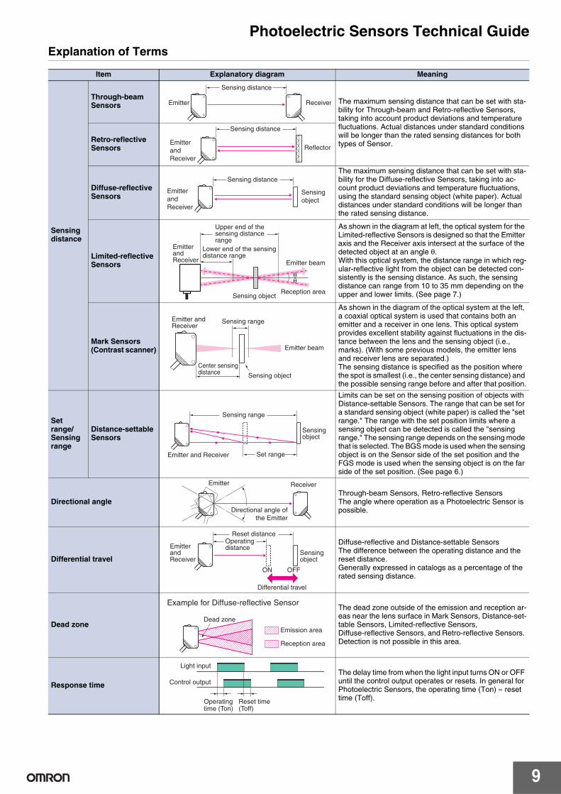
Through-beam Sensors The maximum sensing distance that can be set with sta-
bility for Through-beam and Retro-reflective Sensors, taking into account product deviations and temperature fluctuations. Actual distances under standard conditions will be longer than the rated sensing distances for both types of Sensor.Retro-reflective
Sensors
Diffuse-reflective Sensors
The maximum sensing distance that can be set with sta-bility for the Diffuse-reflective Sensors, taking into ac-count product deviations and temperature fluctuations, using the standard sensing object (white paper). Actual distances under standard conditions will be longer than the rated sensing distance.
Limited-reflective Sensors
As shown in the diagram at left, the optical system for the Limited-reflective Sensors is designed so that the Emitter axis and the Receiver axis intersect at the surface of the detected object at an angle θ.With this optical system, the distance range in which reg-ular-reflective light from the object can be detected con-sistently is the sensing distance. As such, the sensing distance can range from 10 to 35 mm depending on the upper and lower limits. (See page 7.)
Mark Sensors(Contrast scanner)
As shown in the diagram of the optical system at the left, a coaxial optical system is used that contains both an emitter and a receiver in one lens. This optical system provides excellent stability against fluctuations in the dis-tance between the lens and the sensing object (i.e., marks). (With some previous models, the emitter lens and receiver lens are separated.) The sensing distance is specified as the position where the spot is smallest (i.e., the center sensing distance) and the possible sensing range before and after that position.
Set range/Sensing range
Distance-settable Sensors
Limits can be set on the sensing position of objects with Distance-settable Sensors. The range that can be set for a standard sensing object (white paper) is called the "set range." The range with the set position limits where a sensing object can be detected is called the "sensing range." The sensing range depends on the sensing mode that is selected. The BGS mode is used when the sensing object is on the Sensor side of the set position and the FGS mode is used when the sensing object is on the far side of the set position. (See page 6.)
Directional angleThrough-beam Sensors, Retro-reflective SensorsThe angle where operation as a Photoelectric Sensor is possible.
Differential travel
Diffuse-reflective and Distance-settable SensorsThe difference between the operating distance and the reset distance.Generally expressed in catalogs as a percentage of the rated sensing distance.
Dead zone
The dead zone outside of the emission and reception ar-eas near the lens surface in Mark Sensors, Distance-set-table Sensors, Limited-reflective Sensors, Diffuse-reflective Sensors, and Retro-reflective Sensors. Detection is not possible in this area.
Response time
The delay time from when the light input turns ON or OFF until the control output operates or resets. In general for Photoelectric Sensors, the operating time (Ton) ≈ reset time (Toff).
Sensing distance
ReceiverEmitter
EmitterandReceiver
Reflector
Sensing distance
EmitterandReceiver
Sensingobject
Sensing distance
Sensing object
Emitter beam
Reception area
EmitterandReceiver
Upper end of thesensing distancerange
Lower end of the sensingdistance range
θθ
Emitter beam
Center sensingdistance Sensing object
Sensing rangeEmitter andReceiver
Set range
Sensingobject
Sensing range
Emitter and Receiver
Emitter
Directional angle ofthe Emitter
Receiver
Sensingobject
Operatingdistance
Reset distance
ON
Differential travel
OFF
EmitterandReceiver
Example for Diffuse-reflective Sensor
Emission area
Reception area
Dead zone
Light input
Control output
Operatingtime (Ton)
Reset time(Toff)
Photoelectric Sensors Technical Guide
10
Item Explanatory diagram Meaning
Dark-ON operationDARK ON The "Dark-ON" operating mode is when a Through-beam Sensor
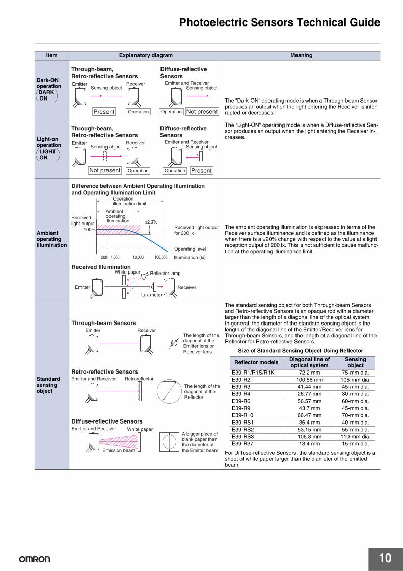
produces an output when the light entering the Receiver is inter-rupted or decreases.
The "Light-ON" operating mode is when a Diffuse-reflective Sen-sor produces an output when the light entering the Receiver in-creases.Light-on
operationLIGHT ON
Ambient operating illumination
The ambient operating illumination is expressed in terms of the Receiver surface illuminance and is defined as the illuminance when there is a ±20% change with respect to the value at a light reception output of 200 lx. This is not sufficient to cause malfunc-tion at the operating illuminance limit.
Standard sensingobject
The standard sensing object for both Through-beam Sensors and Retro-reflective Sensors is an opaque rod with a diameter larger than the length of a diagonal line of the optical system.In general, the diameter of the standard sensing object is the length of the diagonal line of the Emitter/Receiver lens for Through-beam Sensors, and the length of a diagonal line of the Reflector for Retro-reflective Sensors.
Size of Standard Sensing Object Using Reflector
For Diffuse-reflective Sensors, the standard sensing object is a sheet of white paper larger than the diameter of the emitted beam.
Through-beam,Retro-reflective Sensors
Diffuse-reflectiveSensors
Present Operation Not present
Sensing objectEmitter Receiver
Sensing objectEmitter and Receiver
Operation
Through-beam,Retro-reflective Sensors
PresentOperationNot present
Sensing objectEmitter Receiver
Sensing object
Operation
Diffuse-reflectiveSensors
Emitter and Receiver
Difference between Ambient Operating Illuminationand Operating Illumination Limit
Received IlluminationWhite paper Reflector lamp
Lux meter
±20%Received light outputfor 200 lx
Operating level
200 1,000 10,000 100,000 Illumination (lx)
Ambientoperatingillumination
Operationillumination limit
100%
Emitter Receiver
Receivedlight output
Retro-reflective SensorsRetroreflectorEmitter and Receiver
The length of thediagonal of theReflector
Diffuse-reflective SensorsWhite paperEmitter and Receiver
Emission beam
A bigger piece ofblank paper thanthe diameter ofthe Emitter beam
Through-beam Sensors
The length of thediagonal of theEmitter lens orReceiver lens
Emitter Receiver
Reflector models Diagonal line of optical system
Sensingobject
E39-R1/R1S/R1K 72.2 mm 75-mm dia.E39-R2 100.58 mm 105-mm dia.E39-R3 41.44 mm 45-mm dia.E39-R4 26.77 mm 30-mm dia.E39-R6 56.57 mm 60-mm dia.E39-R9 43.7 mm 45-mm dia.E39-R10 66.47 mm 70-mm dia.E39-RS1 36.4 mm 40-mm dia.E39-RS2 53.15 mm 55-mm dia.E39-RS3 106.3 mm 110-mm dia.E39-R37 13.4 mm 15-mm dia.
Photoelectric Sensors Technical Guide
11
Minimum sensing ob-ject
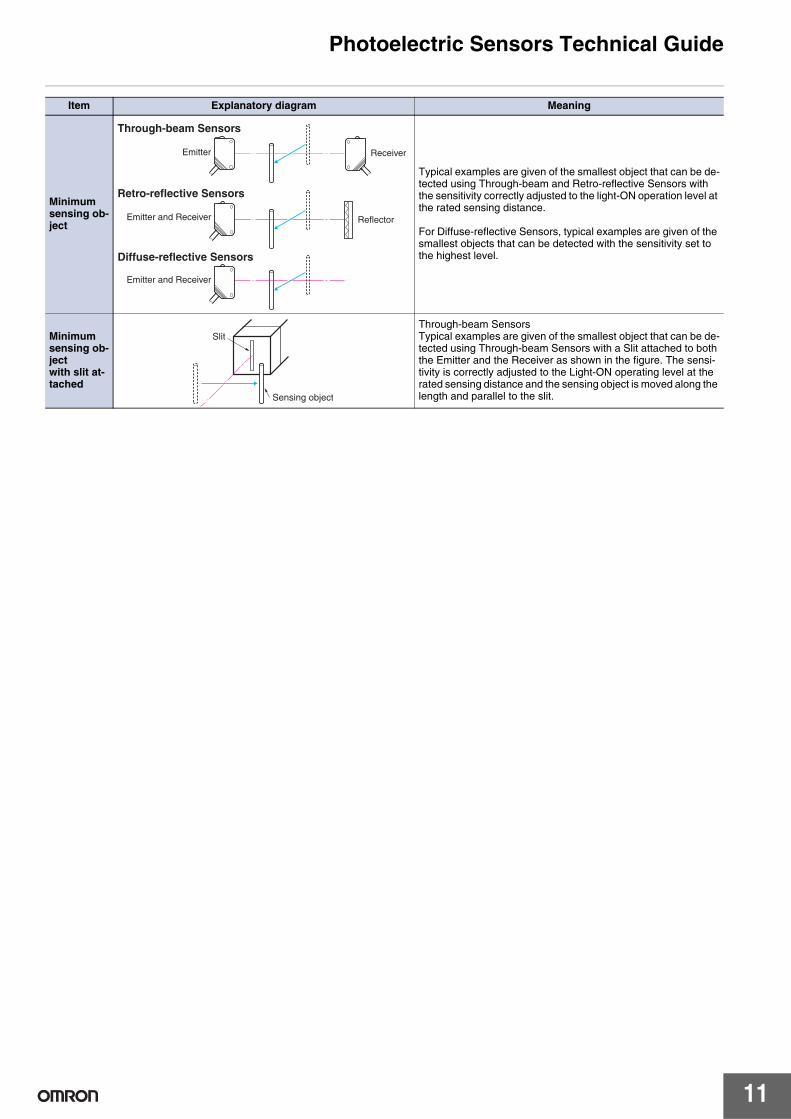
Typical examples are given of the smallest object that can be de-tected using Through-beam and Retro-reflective Sensors with the sensitivity correctly adjusted to the light-ON operation level at the rated sensing distance.
For Diffuse-reflective Sensors, typical examples are given of the smallest objects that can be detected with the sensitivity set to the highest level.
Minimum sensing ob-jectwith slit at-tached
Through-beam SensorsTypical examples are given of the smallest object that can be de-tected using Through-beam Sensors with a Slit attached to both the Emitter and the Receiver as shown in the figure. The sensi-tivity is correctly adjusted to the Light-ON operating level at the rated sensing distance and the sensing object is moved along the length and parallel to the slit.
Item Explanatory diagram Meaning
Through-beam Sensors
Emitter Receiver
Retro-reflective Sensors
ReflectorEmitter and Receiver
Diffuse-reflective Sensors
Emitter and Receiver
Slit
Sensing object
Photoelectric Sensors Technical Guide
14
Application and Data
(1) Relationship of Lens Diameter and Sensitivity to the Smallest Detectable Object
(2) Detecting Height DifferencesSelecting Sensors Based on Detectable Height Differences and Set Distances (Typical Examples)
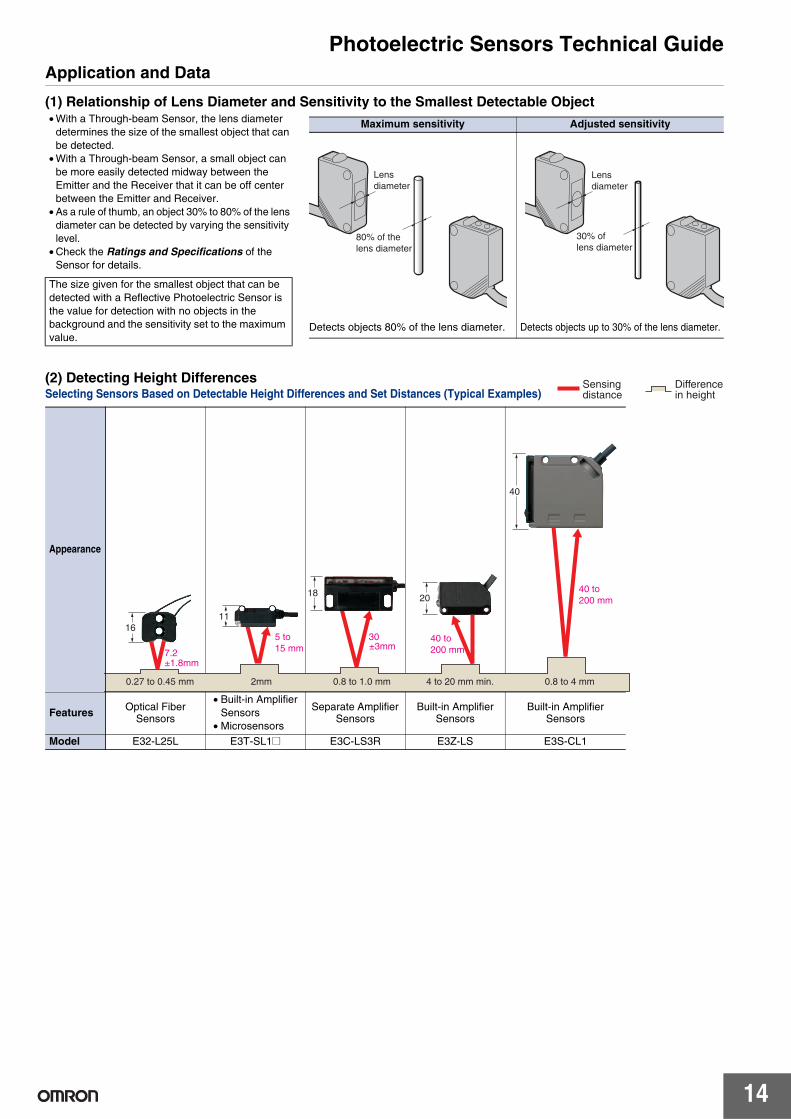
• With a Through-beam Sensor, the lens diameter determines the size of the smallest object that can be detected.
• With a Through-beam Sensor, a small object can be more easily detected midway between the Emitter and the Receiver that it can be off center between the Emitter and Receiver.
• As a rule of thumb, an object 30% to 80% of the lens diameter can be detected by varying the sensitivity level.
• Check the Ratings and Specifications of the Sensor for details.
The size given for the smallest object that can be detected with a Reflective Photoelectric Sensor is the value for detection with no objects in the background and the sensitivity set to the maximum value.
Maximum sensitivity Adjusted sensitivity
Detects objects 80% of the lens diameter. Detects objects up to 30% of the lens diameter.
Lensdiameter
80% of thelens diameter
Lensdiameter
30% oflens diameter
Appearance
Features Optical FiberSensors
• Built-in Amplifier Sensors
• Microsensors
Separate Amplifier Sensors
Built-in Amplifier Sensors
Built-in AmplifierSensors
Model E32-L25L E3T-SL1@ E3C-LS3R E3Z-LS E3S-CL1
Sensingdistance
Differencein height
0.27 to 0.45 mm 2mm 0.8 to 1.0 mm 4 to 20 mm min. 0.8 to 4 mm
7.2±1.8mm
165 to15 mm
11
30±3mm
18
40 to200 mm
2040 to200 mm
40
Photoelectric Sensors Technical Guide
15
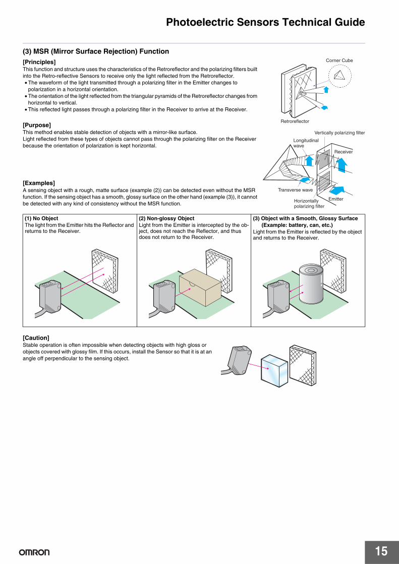
(3) MSR (Mirror Surface Rejection) Function[Principles]This function and structure uses the characteristics of the Retroreflector and the polarizing filters built into the Retro-reflective Sensors to receive only the light reflected from the Retroreflector.• The waveform of the light transmitted through a polarizing filter in the Emitter changes to
polarization in a horizontal orientation.• The orientation of the light reflected from the triangular pyramids of the Retroreflector changes from
horizontal to vertical.• This reflected light passes through a polarizing filter in the Receiver to arrive at the Receiver.
[Purpose]This method enables stable detection of objects with a mirror-like surface.Light reflected from these types of objects cannot pass through the polarizing filter on the Receiver because the orientation of polarization is kept horizontal.
[Examples]A sensing object with a rough, matte surface (example (2)) can be detected even without the MSR function. If the sensing object has a smooth, glossy surface on the other hand (example (3)), it cannot be detected with any kind of consistency without the MSR function.
[Caution]Stable operation is often impossible when detecting objects with high gloss or objects covered with glossy film. If this occurs, install the Sensor so that it is at an angle off perpendicular to the sensing object.
(1) No ObjectThe light from the Emitter hits the Reflector and returns to the Receiver.
(2) Non-glossy ObjectLight from the Emitter is intercepted by the ob-ject, does not reach the Reflector, and thus does not return to the Receiver.
(3) Object with a Smooth, Glossy Surface (Example: battery, can, etc.)
Light from the Emitter is reflected by the object and returns to the Receiver.
Transverse wave
Retroreflector
Corner Cube
Longitudinalwave
Horizontallypolarizing filter
Emitter
Receiver
Vertically polarizing filter
Photoelectric Sensors Technical Guide
16
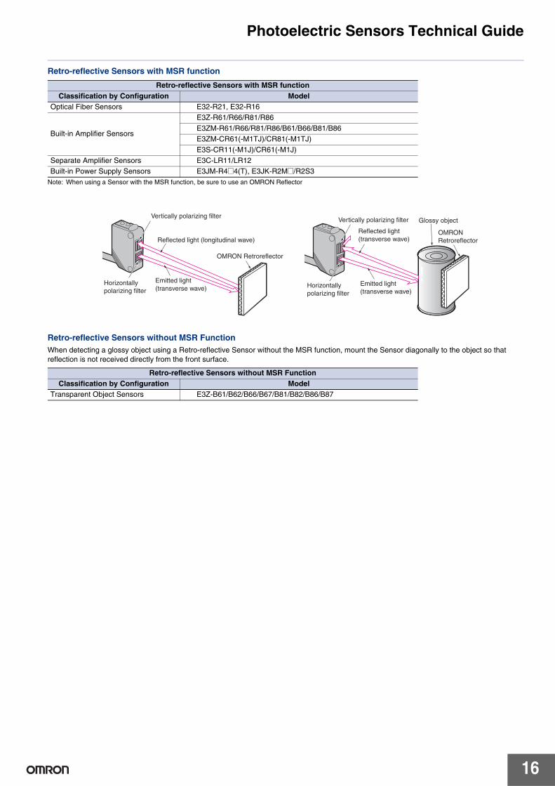
Retro-reflective Sensors with MSR function
Note: When using a Sensor with the MSR function, be sure to use an OMRON Reflector
Retro-reflective Sensors without MSR FunctionWhen detecting a glossy object using a Retro-reflective Sensor without the MSR function, mount the Sensor diagonally to the object so that reflection is not received directly from the front surface.
Retro-reflective Sensors with MSR functionClassification by Configuration Model
Optical Fiber Sensors E32-R21, E32-R16
Built-in Amplifier Sensors
E3Z-R61/R66/R81/R86E3ZM-R61/R66/R81/R86/B61/B66/B81/B86E3ZM-CR61(-M1TJ)/CR81(-M1TJ)E3S-CR11(-M1J)/CR61(-M1J)
Separate Amplifier Sensors E3C-LR11/LR12Built-in Power Supply Sensors E3JM-R4@4(T), E3JK-R2M@/R2S3
Retro-reflective Sensors without MSR FunctionClassification by Configuration Model
Transparent Object Sensors E3Z-B61/B62/B66/B67/B81/B82/B86/B87
Vertically polarizing filter
Reflected light (longitudinal wave)
OMRON Retroreflector
Emitted light(transverse wave)
Horizontallypolarizing filter
Vertically polarizing filter
Reflected light(transverse wave)
Emitted light(transverse wave)
Horizontallypolarizing filter
OMRONRetroreflector
Glossy object
Photoelectric Sensors Technical Guide
17
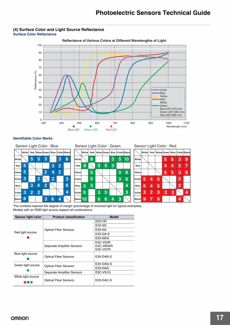
(4) Surface Color and Light Source ReflectanceSurface Color Reflectance
Identifiable Color Marks
The numbers express the degree of margin (percentage of received light for typical examples).Models with an RGB light source support all combinations.
Sensor light color Product classification Model
Red light sourceOptical Fiber Sensors
E3X-HDE3X-SDE3X-NAE3X-DA-SE3X-MDA
Separate Amplifier SensorsE3C-VS3RE3C-VM35RE3C-VS7R
Blue light sourceOptical Fiber Sensors E3X-DAB-S
Green light source Optical Fiber SensorsE3X-DAG-SE3X-NAG
Separate Amplifier Sensors E3C-VS1GWhite light source
Optical Fiber Sensors E3X-DAC-S
Reflectance of Various Colors at Different Wavelengths of Light
0
10
20
30
40
50
60
70
80
90
100
300 400 500 600 700 800 900 1000 1100Wavelength (nm)
Ref
lect
ance
(%
)
VioletBlueYellowRedWhiteGreenBlue LED (470 nm)Green LED (565 nm)Red LED (680 nm)
Blue LED Green LED Red LED
5 6 3 94 4 2 75 5 3
22
44
85 4 56 4 53 2 3 2 29
5533
510
3 3
88
6
364
342
3 8222
553
66
33
43
7 8
5 5 3
3 4 2
38
2
2 23 6 4
5 5 33 5 10
6 4 3
White
Red
Yellow
Green
Blue
Violet
Black
White Red Yellow Green Blue Violet Black
White
Red
Yellow
Green
Blue
Violet
Black
White Red Yellow Green Blue Violet Black
White
Red
Yellow
Green
Blue
Violet
Black
White Red Yellow Green Blue Violet Black
Sensor Light Color : Blue Sensor Light Color : Green Sensor Light Color : Red
Photoelectric Sensors Technical Guide
18
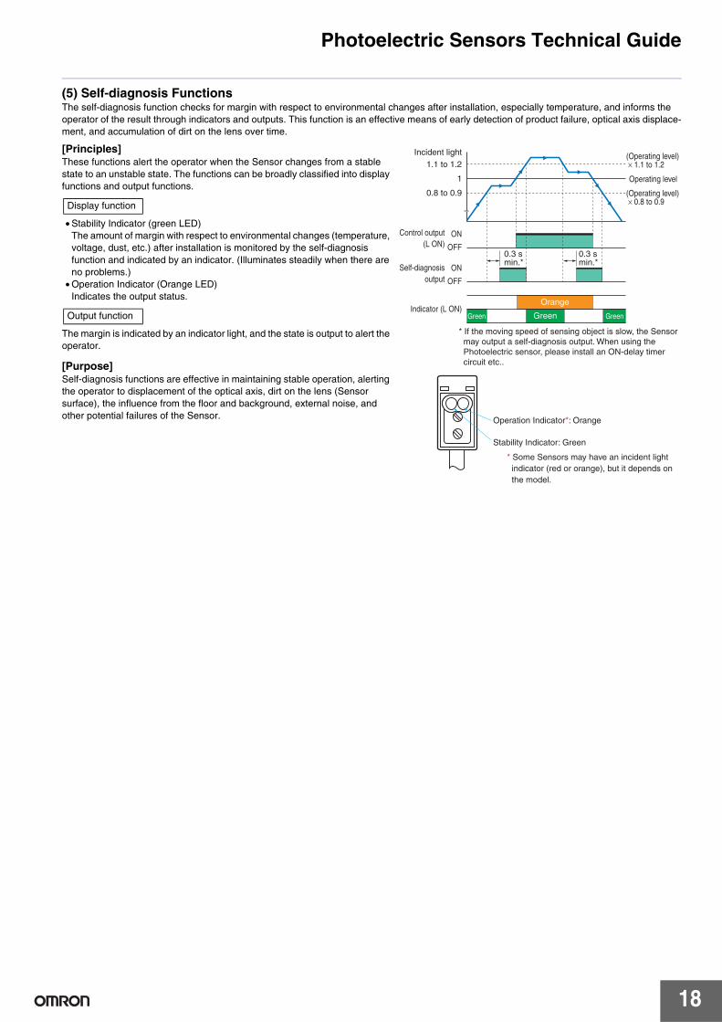
(5) Self-diagnosis FunctionsThe self-diagnosis function checks for margin with respect to environmental changes after installation, especially temperature, and informs the operator of the result through indicators and outputs. This function is an effective means of early detection of product failure, optical axis displace-ment, and accumulation of dirt on the lens over time.
[Principles]These functions alert the operator when the Sensor changes from a stable state to an unstable state. The functions can be broadly classified into display functions and output functions.
• Stability Indicator (green LED)The amount of margin with respect to environmental changes (temperature, voltage, dust, etc.) after installation is monitored by the self-diagnosis function and indicated by an indicator. (Illuminates steadily when there are no problems.)
• Operation Indicator (Orange LED)Indicates the output status.
The margin is indicated by an indicator light, and the state is output to alert the operator.
[Purpose]Self-diagnosis functions are effective in maintaining stable operation, alerting the operator to displacement of the optical axis, dirt on the lens (Sensor surface), the influence from the floor and background, external noise, and other potential failures of the Sensor.
Incident light1.1 to 1.2
1
0.8 to 0.9
0.3 s min.*
0.3 s min.*
(Operating level) × 1.1 to 1.2
(Operating level) × 0.8 to 0.9
Operating level
* If the moving speed of sensing object is slow, the Sensor may output a self-diagnosis output. When using the Photoelectric sensor, please install an ON-delay timer circuit etc..
ON
OFF
Control output (L ON)
Indicator (L ON)
ON
OFF
Self-diagnosis output
Operation Indicator*: Orange
Stability Indicator: Green
* Some Sensors may have an incident light indicator (red or orange), but it depends on the model.
Green GreenGreen
Orange
Display function
Output function
Photoelectric Sensors Technical Guide
19
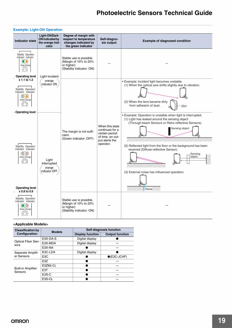
Example: Light-ON Operation
<Applicable Models>
Indicator state
Light-ON/Dark-ON indicated by the orange indi-
cator
Degree of margin with respect to temperature changes indicated by
the green indicator
Self-diagno-sis output Example of diagnosed condition
Light Incidentorange
indicator ON
Stable use is possible. (Margin of 10% to 20% or higher)(Stability indicator: ON)
--- ---
The margin is not suffi-cient.(Green indicator: OFF)
When this state continues for a certain period of time, an out-put alerts the operator.
LightInterrupted
orangeindicator OFF
Stable use is possible. (Margin of 10% to 20% or higher) (Stability indicator: ON)
--- ---
Classification by Configuration Models
Self-diagnosis functionDisplay function Output function
Optical Fiber Sen-sors
E3X-DA-S Digital display ●
E3X-MDA Digital display ---E3X-NA ● ---
Separate Amplifi-er Sensors
E3C-LDA Digital display ●
E3C ● ●(E3C-JC4P)
Built-in Amplifier Sensors
E3Z ● ---E3ZM(-C) ● ---E3T ● ---E3S-C ● ---E3S-CL ● ---
Green Orange
Stability indicator
Operation indicator
Operating level x 1.1 to 1.2
Operating level
Green Orange
Stability indicator
Operationindicator
• Example: Incident light becomes unstable.(1) When the optical axis shifts slightly due to vibration.
(2) When the lens became dirty from adhesion of dust. Dirt
Operating levelx 0.8 to 0.9
Green Orange
Stability indicator
Operationindicator
(1) Light has leaked around the sensing object (Through-beam Sensors or Retro-reflective Sensors).
(2) Reflected light from the floor or the background has been received (Diffuse-reflective Sensor).
(3) External noise has influenced operation.
Sensing object
Sensing object
Noise
• Example: Operation is unstable when light is interrupted.
Green Orange
Stability indicator
Operationindicator
1
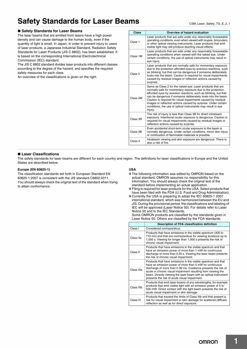
CSM_Laser_Safety_TG_E_2_1Safety Standards for Laser Beams● Safety Standards for Laser BeamsThe laser beams that are emitted from lasers have a high power density and can cause damage to the human body, even if the quantity of light is small. In Japan, in order to prevent injury to users of laser products, a Japanese Industrial Standard, Radiation Safety Standards for Laser Products (JIS C 6802), has been established. It is based on the corresponding International Electrotechnical Commission (IEC) standard.The JIS C 6802 standard divides laser products into different classes according to the degree of the hazard, and specifies the required safety measures for each class.An overview of the classifications is given on the right.
● Laser ClassificationsThe safety standards for laser beams are different for each country and region. The definitions for laser classifications in Europe and the United States are described below.
Europe (EN 60825-1)The classification standards set forth in European Standard EN 60825-1:2007 is consistent with the JIS standard C6802:2011.You should always check the original text of the standard when trying to attain conformance.
USA* The following information was edited by OMRON based on the
actual standard. OMRON assumes no responsibility for this information. You should always check the original text of the standard before implementing an actual application.
* Filing is required for laser products for the USA. Select products that have been filed with the FDA (U.S. Food and Drug Administration).
* Currently the USA is preparing to adopt the IEC 60825-1 2007 international standard, which was harmonized between the EU and JIS. During the provisional period, the classifications and labeling of IEC will be approved (Laser Notice 50). For details refer to Laser Notice 50 and to the IEC Standards.Some OMRON products are classified by the standards given in Laser Notice 50. Others are classified by the FDA standards.
Class Overview of hazard evaluation
Class 1
Laser products that are safe under any reasonably foreseeable operating conditions, even when viewed with loupes, binoculars, or other optical viewing instruments. Laser products that emit visible light may still produce dazzling visual effects.
Class 1M
Laser products that are safe under any reasonably foreseeable operating conditions when viewed with the naked eye. Under certain conditions, the use of optical instruments may result in eye injury.
Class 2
Laser products that are normally safe for momentary exposure due to the protection afforded eyes by aversion reactions, such as blinking, but that can be dangerous if someone deliberately looks into the beam. Caution is required for visual impairments caused by residual images or reflection actions caused by surprise.
Class 2M
Same as Class 2 for the naked eye: Laser products that are normally safe for momentary exposure due to the protection afforded eyes by aversion reactions, such as blinking, but that can be dangerous if someone deliberately looks into the beam. Caution is required for visual impairments caused by residual images or reflection actions caused by surprise. Under certain conditions, the use of optical instruments may result in eye injury.
Class 3R
The risk of injury is less than Class 3B for direct intrabeam exposure. Intentional ocular exposure is dangerous. Caution is required for visual impairments caused by residual images or reflection actions caused by surprise.
Class 3BEven accidental short-term ocular exposure to the beam is normally dangerous. Under certain conditions, minor skin injury or combustion of flammable materials is possible.
Class 4 Intrabeam viewing and skin exposure are dangerous. There is also a risk of fire.
Description of FDA classification definition
Class I Considered nonhazardous.
Class IIa
Products that have emissions in the visible spectrum (400 to 710 nm) and that are nonhazardous for viewing durations up to 1,000 s. Viewing for longer than 1,000 s presents the risk of chronic visual impairment.
Class II
Products that have emissions in the visible spectrum and that have an emission power of more than 1 mW for continuous discharge of more than 0.25 s. Viewing the laser beam presents the risk of chronic visual impairment.
Class IIIa
Products that have emissions in the visible spectrum and that have an emission power of more than 5 mW for continuous discharge of more than 0.38 ms. Irradiance presents the risk of acute or chronic visual impairment resulting from viewing the beam. Directly viewing the laser beam with an optical instrument presents the risk of acute visual impairment.
Class IIIb
Products that emit laser beams of any wavelengths, for example products that emit visible light with an emission power of 5 to 500 mW. Direct contact with the light beam presents the risk of acute visual impairment or skin damage.
Class IVProducts that exceed the limits of Class IIIb and that present a risk for visual impairment or skin damage for scattered (diffuse) reflection as well as for direct exposure.
Safety Standards for Laser Beams
2
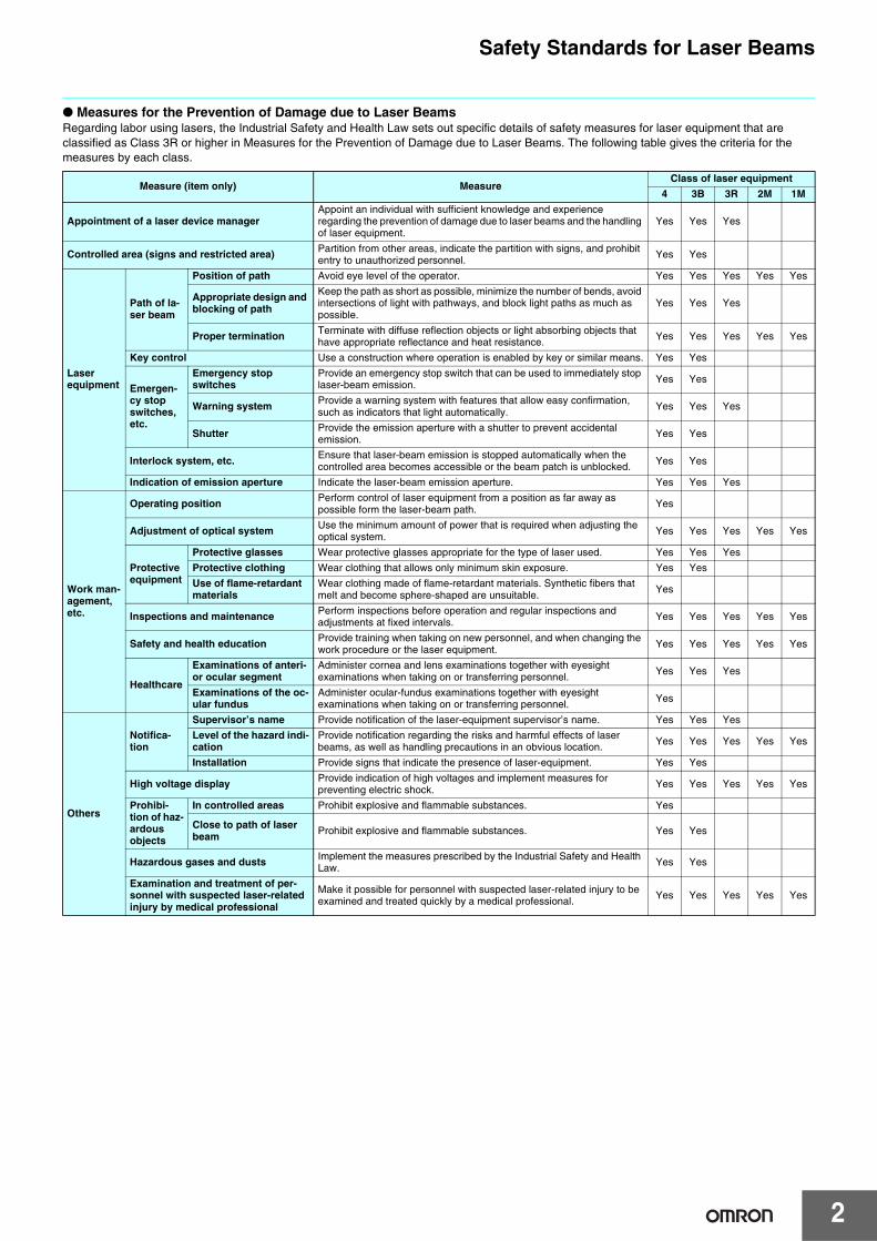
● Measures for the Prevention of Damage due to Laser BeamsRegarding labor using lasers, the Industrial Safety and Health Law sets out specific details of safety measures for laser equipment that are classified as Class 3R or higher in Measures for the Prevention of Damage due to Laser Beams. The following table gives the criteria for the measures by each class.
Measure (item only) MeasureClass of laser equipment
4 3B 3R 2M 1M
Appointment of a laser device managerAppoint an individual with sufficient knowledge and experience regarding the prevention of damage due to laser beams and the handling of laser equipment.
Yes Yes Yes
Controlled area (signs and restricted area) Partition from other areas, indicate the partition with signs, and prohibit entry to unauthorized personnel.
Yes Yes
Laser equipment
Path of la-ser beam
Position of path Avoid eye level of the operator. Yes Yes Yes Yes Yes
Appropriate design and blocking of path
Keep the path as short as possible, minimize the number of bends, avoid intersections of light with pathways, and block light paths as much as possible.
Yes Yes Yes
Proper termination Terminate with diffuse reflection objects or light absorbing objects that have appropriate reflectance and heat resistance.
Yes Yes Yes Yes Yes
Key control Use a construction where operation is enabled by key or similar means. Yes Yes
Emergen-cy stop switches, etc.
Emergency stop switches
Provide an emergency stop switch that can be used to immediately stop laser-beam emission. Yes Yes
Warning system Provide a warning system with features that allow easy confirmation, such as indicators that light automatically. Yes Yes Yes
Shutter Provide the emission aperture with a shutter to prevent accidental emission. Yes Yes
Interlock system, etc. Ensure that laser-beam emission is stopped automatically when the controlled area becomes accessible or the beam patch is unblocked. Yes Yes
Indication of emission aperture Indicate the laser-beam emission aperture. Yes Yes Yes
Work man-agement, etc.
Operating position Perform control of laser equipment from a position as far away as possible form the laser-beam path. Yes
Adjustment of optical system Use the minimum amount of power that is required when adjusting the optical system. Yes Yes Yes Yes Yes
Protective equipment
Protective glasses Wear protective glasses appropriate for the type of laser used. Yes Yes Yes
Protective clothing Wear clothing that allows only minimum skin exposure. Yes Yes
Use of flame-retardant materials
Wear clothing made of flame-retardant materials. Synthetic fibers that melt and become sphere-shaped are unsuitable. Yes
Inspections and maintenance Perform inspections before operation and regular inspections and adjustments at fixed intervals. Yes Yes Yes Yes Yes
Safety and health education Provide training when taking on new personnel, and when changing the work procedure or the laser equipment. Yes Yes Yes Yes Yes
Healthcare
Examinations of anteri-or ocular segment
Administer cornea and lens examinations together with eyesight examinations when taking on or transferring personnel. Yes Yes Yes
Examinations of the oc-ular fundus
Administer ocular-fundus examinations together with eyesight examinations when taking on or transferring personnel. Yes
Others
Notifica-tion
Supervisor’s name Provide notification of the laser-equipment supervisor’s name. Yes Yes Yes
Level of the hazard indi-cation
Provide notification regarding the risks and harmful effects of laser beams, as well as handling precautions in an obvious location. Yes Yes Yes Yes Yes
Installation Provide signs that indicate the presence of laser-equipment. Yes Yes
High voltage display Provide indication of high voltages and implement measures for preventing electric shock. Yes Yes Yes Yes Yes
Prohibi-tion of haz-ardous objects
In controlled areas Prohibit explosive and flammable substances. Yes
Close to path of laser beam Prohibit explosive and flammable substances. Yes Yes
Hazardous gases and dusts Implement the measures prescribed by the Industrial Safety and Health Law. Yes Yes
Examination and treatment of per-sonnel with suspected laser-related injury by medical professional
Make it possible for personnel with suspected laser-related injury to be examined and treated quickly by a medical professional. Yes Yes Yes Yes Yes
Safety Standards for Laser Beams
3
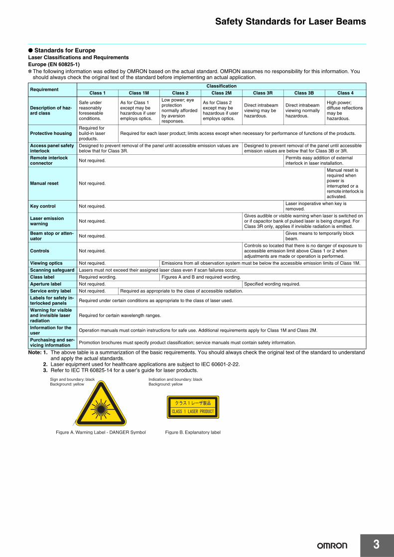
● Standards for EuropeLaser Classifications and RequirementsEurope (EN 60825-1)* The following information was edited by OMRON based on the actual standard. OMRON assumes no responsibility for this information. You
should always check the original text of the standard before implementing an actual application.
Note: 1. The above table is a summarization of the basic requirements. You should always check the original text of the standard to understand and apply the actual standards.
2. Laser equipment used for healthcare applications are subject to IEC 60601-2-22.3. Refer to IEC TR 60825-14 for a user’s guide for laser products.
RequirementClassification
Class 1 Class 1M Class 2 Class 2M Class 3R Class 3B Class 4
Description of haz-ard class
Safe under reasonably foreseeable conditions.
As for Class 1 except may be hazardous if user employs optics.
Low power; eye protection normally afforded by aversion responses.
As for Class 2 except may be hazardous if user employs optics.
Direct intrabeam viewing may be hazardous.
Direct intrabeam viewing normally hazardous.
High power; diffuse reflections may be hazardous.
Protective housingRequired for build-in laser products.
Required for each laser product; limits access except when necessary for performance of functions of the products.
Access panel safety interlock
Designed to prevent removal of the panel until accessible emission values are below that for Class 3R.
Designed to prevent removal of the panel until accessible emission values are below that for Class 3B or 3R.
Remote interlock connector Not required.
Permits easy addition of external interlock in laser installation.
Manual reset Not required.
Manual reset is required when power is interrupted or a remote interlock is activated.
Key control Not required. Laser inoperative when key is removed.
Laser emission warning Not required.
Gives audible or visible warning when laser is switched on or if capacitor bank of pulsed laser is being charged. For Class 3R only, applies if invisible radiation is emitted.
Beam stop or atten-uator Not required. Gives means to temporarily block
beam.
Controls Not required.Controls so located that there is no danger of exposure to accessible emission limit above Class 1 or 2 when adjustments are made or operation is performed.
Viewing optics Not required. Emissions from all observation system must be below the accessible emission limits of Class 1M.
Scanning safeguard Lasers must not exceed their assigned laser class even if scan failures occur.
Class label Required wording. Figures A and B and required wording.
Aperture label Not required. Specified wording required.
Service entry label Not required. Required as appropriate to the class of accessible radiation.
Labels for safety in-terlocked panels Required under certain conditions as appropriate to the class of laser used.
Warning for visible and invisible laser radiation
Required for certain wavelength ranges.
Information for the user Operation manuals must contain instructions for safe use. Additional requirements apply for Class 1M and Class 2M.
Purchasing and ser-vicing information Promotion brochures must specify product classification; service manuals must contain safety information.
Figure A. Warning Label - DANGER Symbol Figure B. Explanatory label
Sign and boundary: black Background: yellow
Indication and boundary: black Background: yellow
Safety Standards for Laser Beams
4
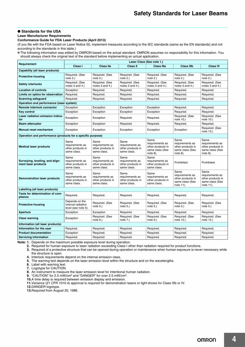
● Standards for the USALaser Manufacturer RequirementsConformance Guide for FDA Laser Products (April 2013)(If you file with the FDA based on Laser Notice 50, implement measures according to the IEC standards (same as the EN standards) and not according to the standards in this table.)* The following information was edited by OMRON based on the actual standard. OMRON assumes no responsibility for this information. You
should always check the original text of the standard before implementing an actual application.
Note: 1. Depends on the maximum possible exposure level during operation.2. Required for human exposure to laser radiation exceeding Class I other than radiation required for product functions.3. Required of a protective structure that can be opened during operation or maintenance when human exposure is never necessary while
the structure is open.4. Interlock requirements depend on the internal emission class.5. The warning text depends on the laser emission level within the structure and on the wavelengths.6. Label with warning text.7. Logotype for CAUTION.8. An instrument to measure the laser emission level for intentional human radiation.9. “CAUTION” for 2.5 mW/cm2 and “DANGER” for over 2.5 mW/cm2.10.A time delay is required between emission display and emission.11.Variance (21 CFR 1010.4) approval is required for demonstration lasers or light shows for Class IIIb or IV.12.DANGER logotype.13.Required from August 20, 1986.
RequirementLaser Class (See note 1.)
Class I Class IIa Class II Class IIIa Class IIIb Class IV
Capability (all laser products)
Protective housing Required. (See note 2.)
Required. (See note 2.)
Required. (See note 2.)
Required. (See note 2.)
Required. (See note 2.)
Required. (See note 2.)
Safety interlocks Required. (See notes 3 and 4.)
Required. (See notes 3 and 4.)
Required. (See notes 3 and 4.)
Required. (See notes 3 and 4.)
Required. (See notes 3 and 4.)
Required. (See notes 3 and 4.)
Location of controls Exception Required. Required. Required. Required. Required.
Limits on optics for observation Required. Required. Required. Required. Required. Required.
Scanning safeguard Required. Required. Required. Required. Required. Required.
Operation and performance (laser system)
Remote interlock connector Exception Exception Exception Exception Required. Required.
Key control Exception Exception Exception Exception Required. Required.
Laser radiation emission indica-tor Exception Exception Required. Required. Required. (See
note 10.)Required. (See note 10.)
Beam attenuator Exception Exception Required. Required. Required. Required.
Manual reset mechanism Exception Exception Exception Exception Exception Required. (See note 13.)
Operation and performance (products for a specific purpose)
Medical laser products
Same requirements as other products in same class.
Same requirements as other products in same class.
Same requirements as other products in same class.
Same requirements as other products in same class (See note 8).
Same requirements as other products in same class (See note 8).
Same requirements as other products in same class (See note 8).
Surveying, leveling, and align-ment laser products
Same requirements as other products in same class.
Same requirements as other products in same class.
Same requirements as other products in same class.
Same requirements as other products in same class.
Prohibited. Prohibited.
Demonstration laser products
Same requirements as other products in same class.
Same requirements as other products in same class.
Same requirements as other products in same class.
Same requirements as other products in same class.
Same requirements as other products in same class (See note 11).
Same requirements as other products in same class (See note 11).
Labelling (all laser products)
Tests for determination of com-pliance Required. Required. Required. Required. Required. Required.
Protective housingDepends on the internal radiation level (see note 5).
Required. (See note 5.)
Required. (See note 5.)
Required. (See note 5.)
Required. (See note 5.)
Required. (See note 5.)
Aperture Exception Exception Required. Required. Required. Required.
Class warning Exception Required. (See note 6.)
Required. (See note 7.)
Required. (See note 9.)
Required. (See note 12.)
Required. (See note 12.)
Information (all laser products)
Information for the user Required. Required. Required. Required. Required. Required.
Product documentation Exception Required. Required. Required. Required. Required.
Servicing information Required. Required. Required. Required. Required. Required.
Safety Standards for Laser Beams
5
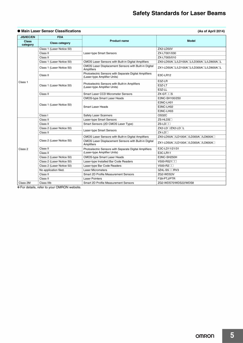
● Main Laser Sensor Classifications (As of April 2014)
* For details, refer to your OMRON website.
JIS/IEC/EN FDAProduct name ModelClass
category Class category
Class 1
Class 1 (Laser Notice 50)
Laser-type Smart Sensors
ZX2-LD50V
Class II ZX-LT001/030
Class II ZX-LT005/010
Class 1 (Laser Notice 50) CMOS Laser Sensors with Built-in Digital Amplifiers ZX0-LD50A@L/LD100A@L/LD300A@L/LD600A@L
Class 1 (Laser Notice 50)CMOS Laser Displacement Sensors with Built-in Digital Amplifiers
ZX1-LD50A@L/LD100A@L/LD300A@L/LD600A@L
Class II Photoelectric Sensors with Separate Digital Amplifiers (Laser-type Amplifier Units)
E3C-LR12
Class 1 (Laser Notice 50)Photoelectric Sensors with Built-in Amplifiers (Laser-type Amplifier Units)
E3Z-LR
E3Z-LT
E3Z-LL
Class II Smart Laser CCD Micrometer Sensors ZX-GT@@S
Class 1 (Laser Notice 50)
CMOS-type Smart Laser Heads E3NC-SH100/250
Smart Laser Heads
E3NC-LH01
E3NC-LH02
E3NC-LH03
Class I Safety Laser Scanners OS32C
Class 2
Class II Laser-type Smart Sensors ZS-HLDS@Class II Smart Sensors (2D CMOS Laser Type) ZS-LD@@Class 2 (Laser Notice 50)
Laser-type Smart SensorsZX2-LD@/ZX2-LD@L
Class II ZX-LD@
Class 2 (Laser Notice 50)CMOS Laser Sensors with Built-in Digital Amplifiers ZX0-LD50A@/LD100A@/LD300A@/LD600A@CMOS Laser Displacement Sensors with Built-in Digital Amplifiers ZX1-LD50A@/LD100A@/LD300A@/LD600A@
Class II Photoelectric Sensors with Separate Digital Amplifiers (Laser-type Amplifier Units)
E3C-LD11/21/31
Class II E3C-LR11
Class 2 (Laser Notice 50) CMOS-type Smart Laser Heads E3NC-SH250H
Class 2 (Laser Notice 50) Laser-type Installed Bar Code Readers V500-R521@@Class 2 (Laser Notice 50) Laser-type Bar Code Readers V500-R2@@No application filed. Laser Micrometers 3Z4L-S5@@RV3
Class II Smart 2D Profile Measurement Sensors ZG2-WDS3V
Class II Laser Pointers F39-PTJ/PTR
Class 2M Class IIIb Smart 2D Profile Measurement Sensors ZG2-WDS70/WDS22/WDS8
Safety Standards for Laser Beams
6
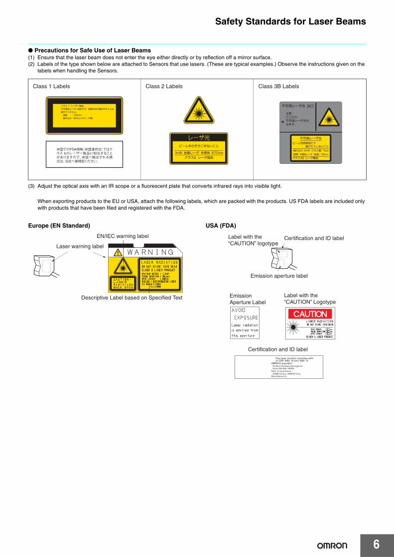
● Precautions for Safe Use of Laser Beams(1) Ensure that the laser beam does not enter the eye either directly or by reflection off a mirror surface.(2) Labels of the type shown below are attached to Sensors that use lasers. (These are typical examples.) Observe the instructions given on the
labels when handling the Sensors.
(3) Adjust the optical axis with an IR scope or a fluorescent plate that converts infrared rays into visible light.
When exporting products to the EU or USA, attach the following labels, which are packed with the products. US FDA labels are included only with products that have been filed and registered with the FDA.
Europe (EN Standard) USA (FDA)
Class 1 Labels Class 2 Labels Class 3B Labels
Laser warning label
EN/IEC warning label
Descriptive Label based on Specified Text
Certification and ID label
Certification and ID label
Emission aperture label
Label with the “CAUTION” logotype
Label with the “CAUTION” Logotype
Emission Aperture Label