phased array simulation with beamforming for 5g …...• adaptive channel estimation / equalization...
TRANSCRIPT
Phased Array Simulation with Beamforming for 5G System
Nash Tu
AE, Keysight EEsof
June, 2017
Page
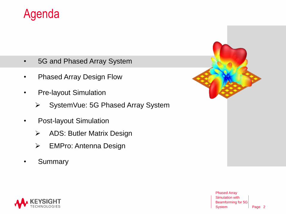
Agenda
• 5G and Phased Array System
• Phased Array Design Flow
• Pre-layout Simulation
SystemVue: 5G Phased Array System
• Post-layout Simulation
ADS: Butler Matrix Design
EMPro: Antenna Design
• Summary
Phased Array
Simulation with
Beamforming for 5G
System 2
Page
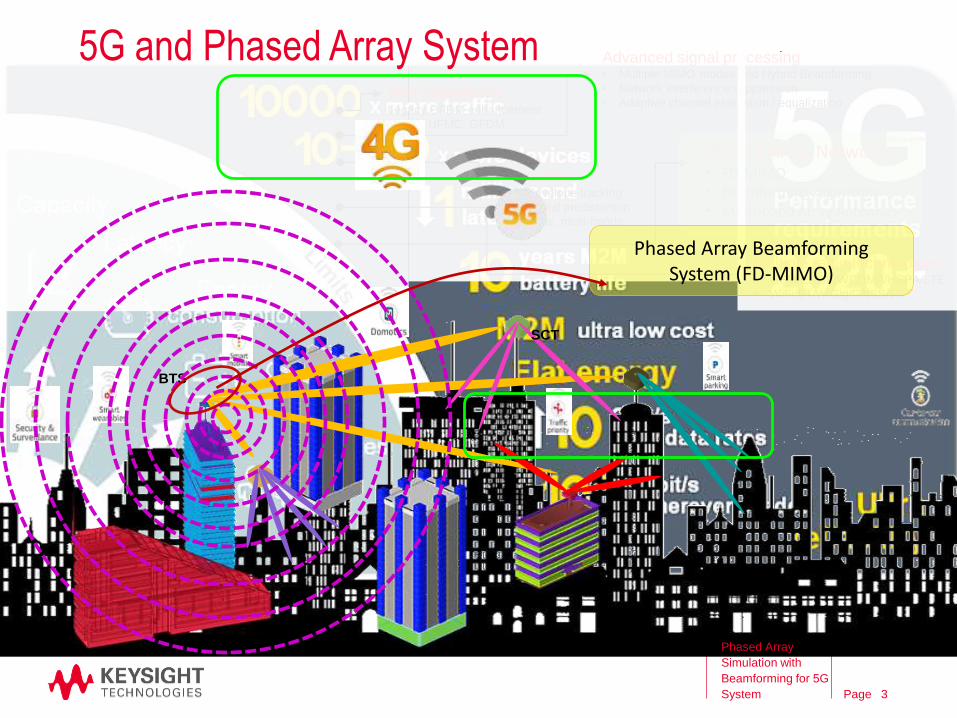
BTS
SCT
Multiple radio technologies• GSM/EDGE/WCDMA/HSPA/LTE
• WiFi/BT/WiGig/GNSS/5G
New waveformsLegacy OFDM enhancement
FBMC, UFMC, GFDM
Advanced signal processing• Multiple MIMO modes and Hybrid Beamforming
• Network interference suppression
• Adaptive channel estimation / equalization
Amplifier• Envelope tracking
• Digital predistortion
• Wide, multi-bands
Phased Array Network• FD-MIMO• Beamforming Algorithm• Multi-band Array Antennas
Phased Array Beamforming System (FD-MIMO)
5G and Phased Array System
Phased Array
Simulation with
Beamforming for 5G
System 3
Page
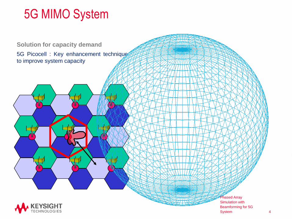
5G MIMO System
5G Picocell : Key enhancement technique
to improve system capacity
User D
ata
-6
Base
Station
User Data-2
Vertical
Beamforming
Horizontal
Beamforming
Solution for capacity demand
Phased Array
Simulation with
Beamforming for 5G
System 4

Page
Agenda
• 5G and Phased Array System
• Phased Array Design Flow
• Pre-layout Simulation
SystemVue: 5G Phased Array System
• Post-layout Simulation
ADS: Butler Matrix Design
EMPro: Antenna Design
• Summary
Phased Array
Simulation with
Beamforming for 5G
System 5
Page
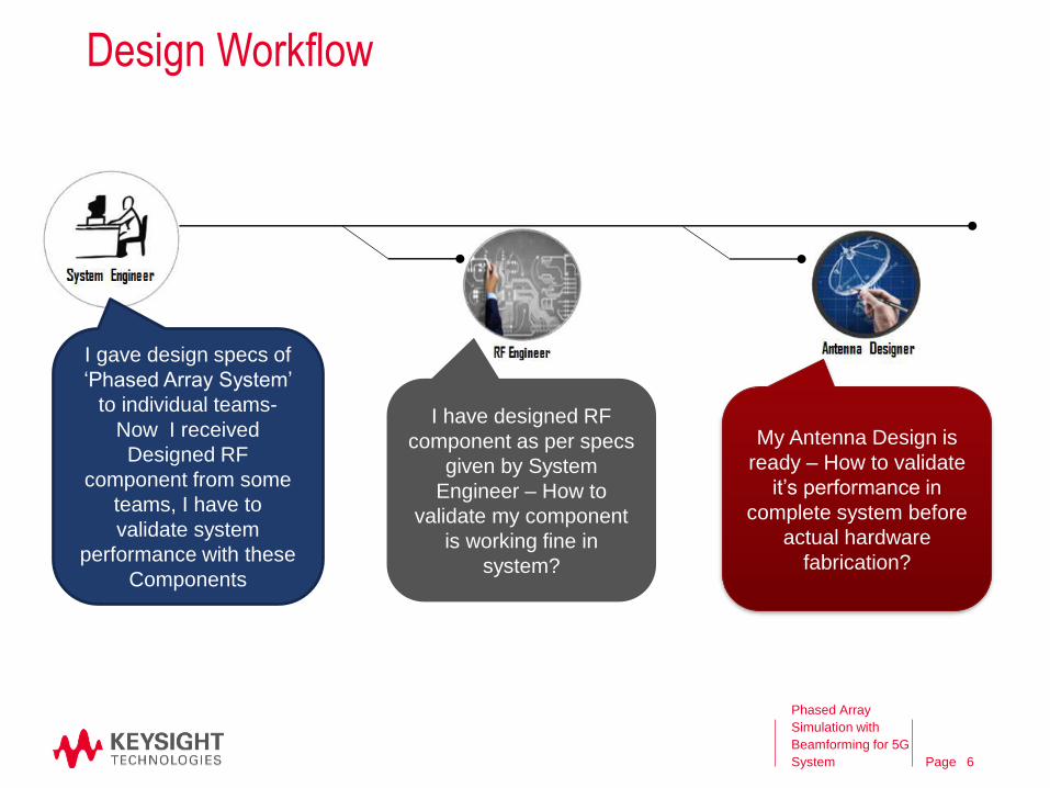
I gave design specs of
‘Phased Array System’
to individual teams-
Now I received
Designed RF
component from some
teams, I have to
validate system
performance with these
Components
I have designed RF
component as per specs
given by System
Engineer – How to
validate my component
is working fine in
system?
My Antenna Design is
ready – How to validate
it’s performance in
complete system before
actual hardware
fabrication?
Design Workflow
Phased Array
Simulation with
Beamforming for 5G
System 6

Page
System DesignRF Level Simulation
RF/Antenna Designs
Circuit Level Simulation
Antenna Design
EM Simulation
• Investigate effects of specific RF
links on antenna pattern
• System level measurements
(EVM, ACPR)
Circuit and antenna affect each other.
• The antenna’s pattern changes with the input
phase and amplitude to the ports.
• The driving circuitry is affected by the input
loads of the antenna’s ports, esp. for power
amplifiers.
1
5
2
6
System Level Design
Drive Phased Array
system with modulated
signals
3
VTB
4
SystemVue ADS EMPro
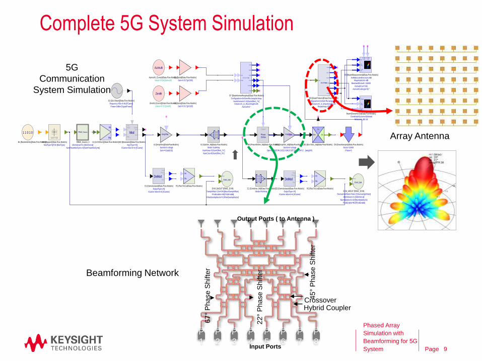
RF Beamforming Network for 5G MIMO System
System Performance with actual
Circuit components
Use SystemVue VTB in ADS
Phased Array Antenna Design
EM Simulations of Antennas
Circuit Design
• RF Circuit design for
of individual
elements(PA,
LNA…) of RF link
• System Performance
with actual Circuit
components
7
RF Beamforming System : EEsof Solution form System Design to Actual Hardware Design and Validation
Phased Array
Simulation with
Beamforming for 5G
System 7
Page
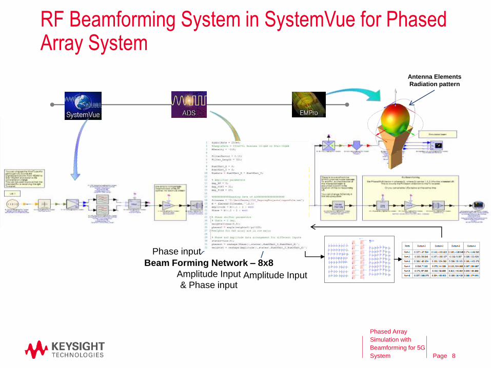
Beam Forming Network – 8x8
Amplitude Input
& Phase input
Antenna Elements
Radiation pattern
Phase input
Amplitude Input
RF Beamforming System in SystemVue for Phased Array System
Phased Array
Simulation with
Beamforming for 5G
System 8
Page
Re
Im
C4 {CxToRect@Data Flow Models}
Amplifier
Gain=4 [sqrt(16)]
GainUnit=voltage
A1 {Amplifier@Data Flow Models}
Power=0 dBm [SignalPower]
Frequency=60e+9 Hz [FCarrier]
O1 {Oscillator@Data Flow Models}
ModOUT
QUAD
OUT
Freq
Phase
Q
I
Amp
FCarrier=60e+9 Hz [FCarrier]
InputType=I/Q
M2 {Modulator@Data Flow Models}
PhaseShifter
Control
I O
M3 {PhaseShifter_M@Data Flow Models}
[]
[][]
[]
[]
[][]
[]
NumCols=8 [NumOfAnt_XV]
NumRows=8 [NumOfAnt_YV]
Mode=SubArray
S1 {Splitter_M@Data Flow Models}
FBMC_Source
NumPreambleSyms=6 [NumPreambleSyms]
IdleInterval=0 s [IdleInterval]
FBMC_Source_1
• • •• • •
• • • • • •
MAPPER
ModType=QPSK [ModType]
M1 {Mapper@Data Flow Models}
1 1 0 1 0
B1 {RandomBits@Data Flow Models}
[][][]
[][]
[][]
[]
Mode=FullArray
C1 {Combiner_M@Data Flow Models}
Re
Im
R1 {RectToCx@Data Flow Models}
DeMod I
Amp
Freq
Phase
Q
FCarrier=60e+9 Hz [FCarrier]
OutputType=I/Q
D1 {Demodulator@Data Flow Models}
FBMC_EVM
Data_In
Ref
FilterOverlapFactor=4 [FilterOverlapFactor]
PilotEnable=NO [PilotEnable]
SampleRate=10e+6 Hz [BaseSampleRate]
EVM_BefDUT {FBMC_EVM}
Amplifier
Gain=(8x8) [0.04,0.032,0.043,0.037,0.04,0.041,0… [weightV]
GainUnit=voltage
M13 {Amplifier_M@Data Flow Models}
Fc
CxEnv
E1 {EnvToCx_M@Data Flow Models}
Phase=0
Factor=10000
D3 {DownSample@Data Flow Models}
Re
Im
R2 {RectToCx@Data Flow Models}
DeMod I
Amp
Freq
Phase
Q
FCarrier=60e+9 Hz [FCarrier]
OutputType=I/Q
D2 {Demodulator@Data Flow Models}
FBMC_EVM
Data_In
Ref
PilotEnable=NO [PilotEnable]
NumDataSyms=20 [NumDataSyms]
IdleInterval=0 s [IdleInterval]
OversampleRatio=Ratio 2 [OversampleRatio]
EVM_AftDUT {FBMC_EVM}
Gain=0.017 [pi/180]
G2 {Gain@Data Flow Models}
Azimuth
Value=0.524 [Azimuth]
Azimuth1 {Const@Data Flow Models}
Zenith
Value=4.712 [Zenith]
Zenith1 {Const@Data Flow Models}
Gain=0.017 [pi/180]
G1 {Gain@Data Flow Models} Beam form erWeights
OutputZ
OutputY
OutputX
Phases
M agni tudes
Weights
Zenith
Az imuth
Azimuth=0 °
DistanceX_in_Wavelengths=0.5NumElementsY=8 [NumOfAnt_YV]
Configuration=Uniform Rectangular Array
B7 {BeamformerWeights@Data Flow Models}
BeamPattern
OutputZ
OutputY
OutputX
AntennaGain
Zenith
Az imuth
Input
RotateArray=NODistanceX_in_Wavelengths=0.5
Configuration=Uniform Rectangular Array
B6 {BeamPattern@Data Flow Models} Z
M agnitude
YZenith(Theta)
XAz imuth(Phi)
MinLevel_dB=-30
CoordinateSystem=Spherical
Beam {Dynamic3D@Data Flow Models}
M ag
Zenith
(Theta)
Az imuth
(Phi)
M ain Lobes
Az imuth
M ain Lobes
Zenith
AzimuthCutAngle=30 °
AzimuthCut=YES
BeamwidthLevel=-3 dB10
MagnitudeUnit=dBiSetMainLobeDirections=NO
B3 {BeamMeasurement@Data Flow Models}
Array Antenna
Beamforming Network
5G
Communication
System Simulation
P
1
P
2
P
3
P
4
P
5
P
6
P
7
P
8
Output Ports ( to Antenna )
Input Ports
Hybrid CouplerCrossover
67
°P
ha
se
Sh
ifte
r
22
°P
ha
se
Sh
ifte
r
45
°P
ha
se
Sh
ifte
r
Complete 5G System Simulation
Phased Array
Simulation with
Beamforming for 5G
System 9
Page
Re
Im
C4 {CxToRect@Data Flow Models}
Amplifier
Gain=4 [sqrt(16)]
GainUnit=voltage
A1 {Amplifier@Data Flow Models}
Power=0 dBm [SignalPower]
Frequency=60e+9 Hz [FCarrier]
O1 {Oscillator@Data Flow Models}
ModOUT
QUAD
OUT
Freq
Phase
Q
I
Amp
FCarrier=60e+9 Hz [FCarrier]
InputType=I/Q
M2 {Modulator@Data Flow Models}
PhaseShifter
Control
I O
M3 {PhaseShifter_M@Data Flow Models}
[]
[][]
[]
[]
[][]
[]
NumCols=8 [NumOfAnt_XV]
NumRows=8 [NumOfAnt_YV]
Mode=SubArray
S1 {Splitter_M@Data Flow Models}
FBMC_Source
NumPreambleSyms=6 [NumPreambleSyms]
IdleInterval=0 s [IdleInterval]
FBMC_Source_1
• • •• • •
• • • • • •
MAPPER
ModType=QPSK [ModType]
M1 {Mapper@Data Flow Models}
1 1 0 1 0
B1 {RandomBits@Data Flow Models}
[][][]
[][]
[][]
[]
Mode=FullArray
C1 {Combiner_M@Data Flow Models}
Re
Im
R1 {RectToCx@Data Flow Models}
DeMod I
Amp
Freq
Phase
Q
FCarrier=60e+9 Hz [FCarrier]
OutputType=I/Q
D1 {Demodulator@Data Flow Models}
FBMC_EVM
Data_In
Ref
FilterOverlapFactor=4 [FilterOverlapFactor]
PilotEnable=NO [PilotEnable]
SampleRate=10e+6 Hz [BaseSampleRate]
EVM_BefDUT {FBMC_EVM}
Amplifier
Gain=(8x8) [0.04,0.032,0.043,0.037,0.04,0.041,0… [weightV]
GainUnit=voltage
M13 {Amplifier_M@Data Flow Models}
Fc
CxEnv
E1 {EnvToCx_M@Data Flow Models}
Phase=0
Factor=10000
D3 {DownSample@Data Flow Models}
Re
Im
R2 {RectToCx@Data Flow Models}
DeMod I
Amp
Freq
Phase
Q
FCarrier=60e+9 Hz [FCarrier]
OutputType=I/Q
D2 {Demodulator@Data Flow Models}
FBMC_EVM
Data_In
Ref
PilotEnable=NO [PilotEnable]
NumDataSyms=20 [NumDataSyms]
IdleInterval=0 s [IdleInterval]
OversampleRatio=Ratio 2 [OversampleRatio]
EVM_AftDUT {FBMC_EVM}
Gain=0.017 [pi/180]
G2 {Gain@Data Flow Models}
Azimuth
Value=0.524 [Azimuth]
Azimuth1 {Const@Data Flow Models}
Zenith
Value=4.712 [Zenith]
Zenith1 {Const@Data Flow Models}
Gain=0.017 [pi/180]
G1 {Gain@Data Flow Models} Beam form erWeights
OutputZ
OutputY
OutputX
Phases
M agni tudes
Weights
Zenith
Az imuth
Azimuth=0 °
DistanceX_in_Wavelengths=0.5NumElementsY=8 [NumOfAnt_YV]
Configuration=Uniform Rectangular Array
B7 {BeamformerWeights@Data Flow Models}
BeamPattern
OutputZ
OutputY
OutputX
AntennaGain
Zenith
Az imuth
Input
RotateArray=NODistanceX_in_Wavelengths=0.5
Configuration=Uniform Rectangular Array
B6 {BeamPattern@Data Flow Models} Z
M agnitude
YZenith(Theta)
XAz imuth(Phi)
MinLevel_dB=-30
CoordinateSystem=Spherical
Beam {Dynamic3D@Data Flow Models}
M ag
Zenith
(Theta)
Az imuth
(Phi)
M ain Lobes
Az imuth
M ain Lobes
Zenith
AzimuthCutAngle=30 °
AzimuthCut=YES
BeamwidthLevel=-3 dB10
MagnitudeUnit=dBiSetMainLobeDirections=NO
B3 {BeamMeasurement@Data Flow Models}
5G Phased Array MIMO System
Baseband
(Digital)Radiating Element
(EM)
Analog
(RF)
PA
LNA
Communicatio
n Data
Signal
Processing
Antenna
ArrayLO
DA
C
AD
C
TX
RX
BFN
Block Level 5G Design
System Level Design
Actual Hardware Design
BFN
Phased Array
Simulation with
Beamforming for 5G
System 10
Page
Agenda
• 5G and Phased Array System
• Phased Array Design Flow
• Pre-layout Simulation
SystemVue: 5G Phased Array System
• Post-layout Simulation
ADS: Butler Matrix Design
EMPro: Antenna Design
• Summary
Phased Array
Simulation with
Beamforming for 5G
System 11
Page
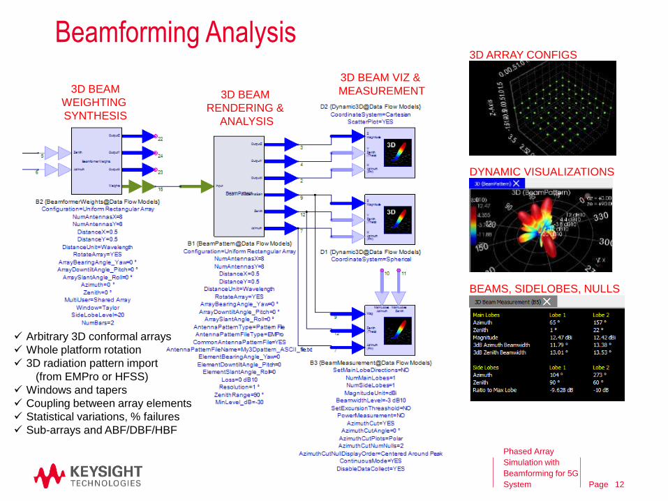
Beamforming Analysis
Phased Array
Simulation with
Beamforming for 5G
System
Arbitrary 3D conformal arrays
Whole platform rotation
3D radiation pattern import
(from EMPro or HFSS)
Windows and tapers
Coupling between array elements
Statistical variations, % failures
Sub-arrays and ABF/DBF/HBF
3D ARRAY CONFIGS
DYNAMIC VISUALIZATIONS
BEAMS, SIDELOBES, NULLS
3D BEAM
WEIGHTING
SYNTHESIS
3D BEAM
RENDERING &
ANALYSIS
3D BEAM VIZ &
MEASUREMENT
12
Page
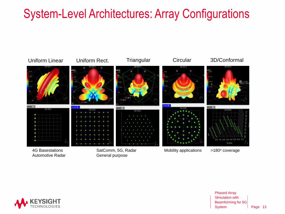
System-Level Architectures: Array Configurations
Phased Array
Simulation with
Beamforming for 5G
System
CircularUniform Rect. 3D/Conformal
4G Basestations
Automotive Radar
SatComm, 5G, Radar
General purpose
Mobility applications >180o coverage
TriangularUniform Linear
13
Page
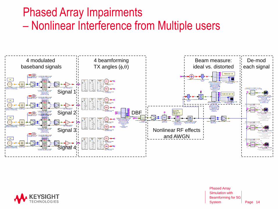
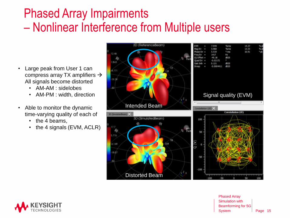
Phased Array Impairments – Nonlinear Interference from Multiple users
Phased Array
Simulation with
Beamforming for 5G
System
Signal 1
Signal 2
Signal 3
Signal 4
4 beamforming
TX angles (f,q)
4 modulated
baseband signals
Nonlinear RF effects
and AWGN
De-mod
each signal
Beam measure:
ideal vs. distorted
DBF
14
Page
Phased Array Impairments – Nonlinear Interference from Multiple users
Phased Array
Simulation with
Beamforming for 5G
System
• Large peak from User 1 can
compress array TX amplifiers
All signals become distorted
• AM-AM : sidelobes
• AM-PM : width, direction
• Able to monitor the dynamic
time-varying quality of each of
• the 4 beams,
• the 4 signals (EVM, ACLR)
Intended Beam
Distorted Beam
Signal quality (EVM)
15
Page
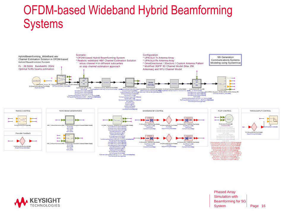
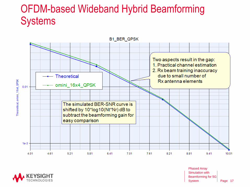
OFDM-based Wideband Hybrid Beamforming Systems
Phased Array
Simulation with
Beamforming for 5G
System
HybridBeamforming_WideBand.wsvChannel Estimation Solution in OFDM-based
Hybrid Beamforming System
5th Generation Communications Systems Modeling using SystemVue
Scenario:* OFDM-based Hybrid Beamforming System* Realistic wideband HBF Channel Estimation Solution* Various channel H in dif ferent subcarriers
* Two step channel estimation approach
Conf iguration:* UPA/ULA Tx Antenna Array* UPA/ULA Rx Antenna Array* OmniDirectional / 3Sectors / Custom Antenna Pattern* Modif ied 3GPP 3D Channel Model (Max 256
Antennas) and NYU Channel Model
TIMING CONTROL TX/RX BEAM GENERATORS WIDEBAND BF CONTROL PLOT CONTROL
Fc : 28.5GHz Bandwidth: 2GHzOptimal Tx/Rx beams estimation
THROUGHPUT CONTROL
Precoder Feedback
1 1 0 1 0
DataPattern=PN9B5 {DataPattern@Data Flow Models}
Noise
Density
NDensity=-58.331 dBm [NDensity_dBm]NDensityType=Constant noise density
A3 {AddNDensity_M@Data Flow Models}
ArrayCoupling_M
CouplingMatrix=(16x16) [1,0,0,0,0,0,0,0,0,0,0,0… [eye(Nt)]
A4 {ArrayCoupling_M@Data Flow Models}
ArrayCoupling_M
CouplingMatrix=(4x4) [1,0,0,0; 0,1,0,0; 0,0,1,0… [eye(Nr)]A1 {ArrayCoupling_M@Data Flow Models}
DataIn
RxWeights
DataOut
R F
R X
RxAntArrayWindowType=NoneRxPhaseShifterDistortion=(4x1)… [RxPhaseShifterDistortion]
RxAntennaArrayMask=(4x1) [1; 1; 1; 1] [ones(Nr,Nrrf)]Nrrf=1 [Nrrf]
NumOfRxAntz=1 [NumOfRxAntz]NumOfRxAnty=4 [NumOfRxAnty]NumOfRxAntx=1 [NumOfRxAntx]
fc=28.5e+9 Hz [fc]Subnetwork2 {RF_Rx_WB}
Flex OFDM M IM O
Sourc e RF
Flex OFDM_Sig
Flex OFDM_Const
Flex OFDM_RF
M IM OPrecoding
DataInfo2
DataInfo1
DFTSize=64 [Num_Subcarriers]FlexOFDM_Source_RF_2 {FlexOFDM_MIMO_Source_RF@5G Advanced Modem Models}
OutputTiming=BeforeInput
D1 {Delay@Data Flow Models}
TEST
REF
StartStopOption=SamplesB1
PlotControl
Wrf
Frf
RxPosition_Z=(4x1) [0; 0; 0; 0] [RxPosition_Z]RxPosition_Y=(4x1) [0; 0.5; 1; 1.5] [RxPosition_Y]
RxPosition_X=(4x1) [0; 0; 0; 0] [RxPosition_X]TxPosition_Z=(16x1) [0; 0; 0; 0; 0.5; 0.5] [TxPosition_Z]
TxPosition_Y=(16x1) [0; 0.5; 1; 1.5; 0; 0.… [TxPosition_Y]TxPosition_X=(16x1) [0; 0; 0; 0; 0; 0; 0] [TxPosition_X]
RxSlantAngle=(4x1) [0; 0; 0; 0] [RxSlantAngle]RxDowntiltAngle=(4x1) [0; 0; 0; 0] [RxDowntiltAngle]RxBearingAngle=(4x1) [0; 0; 0; 0] [RxBearingAngle]
TxSlantAngle=(16x1) [0; 0; 0; 0; 0; 0; 0] [TxSlantAngle]TxDowntiltAngle=(16x1) [0; 0; 0; 0; 0] [TxDowntiltAngle]
TxBearingAngle=(16x1) [0; 0; 0; 0; 0; 0] [TxBearingAngle]Nrrf=1 [Nrrf]
NumOfRxAntz=1 [NumOfRxAntz]
NumOfRxAnty=4 [NumOfRxAnty]NumOfRxAntx=1 [NumOfRxAntx]
RxAntennaPatternType=0Ntrf=1 [Ntrf]
NumOfTxAntz=4 [NumOfTxAntz]NumOfTxAnty=4 [NumOfTxAnty]
NumOfTxAntx=1 [NumOfTxAntx]TxAntennaPatternType=0
Disabled: OPENPlotControl {PlotControl}
OutputTiming=BeforeInputD2 {Delay@Data Flow Models}
TimingControl
Rx Beam Enable
Sy nc Idx_delay
Sy ncEn
Sy ncIdx
TimingControl {TimingControl}
HBF_Tx Beam Generator
Nrrf=1 [Nrrf]Nr=4 [Nr]
Ntrf=1 [Ntrf]
Nt=16 [Nt]HBF_TxBeamGenerator {HBF_TxBeamGenerator@5G Advanced Modem Models}
H B F _ R x B e a m Generator
Rx Weights
Rx Beam Enable
Sy nc Idx_delay
Wrf_Data
Nrrf=1 [Nrrf]
Nr=4 [Nr]Ntrf=1 [Ntrf]Nt=16 [Nt]
HBF_RxBeamGenerator {HBF_RxBeamGenerator@5G Advanced Modem Models}
HBF_Contro l ler_WB
Frf
Wrf
FreSig
RxAntArrayWindowType=NoneRxAntennaArrayMask=(4x1) [1; 1; 1; 1… [RxAntennaArrayMask]
RxPhiRange=(1x2) [-90,89] °
RxThetaRange=(1x2) [0,179] °RxBeamPhiGranularity=1 °
RxBeamThetaGranularity=1 °NumOfRxRFChains=1 [Nrrf]
NumOfRxAntz=1 [NumOfRxAntz]
NumOfRxAnty=4 [NumOfRxAnty]NumOfRxAntx=1 [NumOfRxAntx]
TxAntArrayWindowType=NoneTxAntennaArrayMask=(16x1) [1; 1; 1] [TxAntennaArrayMask]
TxPhiRange=(1x2) [-90,89] °TxThetaRange=(1x2) [0,179] °
TxBeamPhiGranularity=1 °TxBeamThetaGranularity=1 °NumOfTxRFChains=1 [Ntrf]
NumOfTxAntz=4 [NumOfTxAntz]NumOfTxAnty=4 [NumOfTxAnty]
NumOfTxAntx=1 [NumOfTxAntx]H1 {HBF_Controller_WB@5G Advanced Modem Models}
[ ]
Format=ColumnMajorNumCols=1
NumRows=1 [Nrrf]
P2 {PackBus_M@Data Flow Models}
[ ]
Format=ColumnMajorNumCols=1
NumRows=1 [Nrrf]
U2 {UnpackBus_M@Data Flow Models}
[ ]
Format=ColumnMajorNumCols=1
NumRows=1 [Ntrf]U1 {UnpackBus_M@Data Flow Models}
OutputTiming=BeforeInput
N=16 [Nt]D3 {Delay@Data Flow Models}
OutputTiming=BeforeInputN=4 [Nr]
D4 {Delay@Data Flow Models}
M IM O_3DChannel_RF
H
SigOut
SigIn
UseIntraClusterDelays=NOSimPeriod=1e-2 s
MsMovingTheta=90MsMovingPhi=0
BsLOSTheta=90BsLOSPhi=0
RxAntennaPatternType=OmniDirectionalNumberofRx=4 [Nr]
TxAntennaPatternType=OmniDirectional
NumberofTx=16 [Nt]ChannelLinkDirection=Downlink
CarrierFrequency=28.5e+9 Hz [fc]ScenarioType=UserDefined
ChannelModelType=NYU_Model
MIMO_3DChannel_RF_1
FlexO FDM _M I M O _Receiver _RF
p2Out
Sy ncEn
Sy nc Index
Bi ts Out
M IM OPrec odingMatrix
Flex OFDM_RF
DFTSize=64 [Num_Subcarriers]FelxOFDM_Receiver_RF {FlexOFDM_MIMO_Receiver_RF}
DataOutDataIn
TxWeights
R F
T X
TxAntArrayWindowType=NoneTxPhaseShifterDistortion=(16x1… [TxPhaseShifterDistortion]
TxAntennaArrayMask=(16x1) [1; 1; 1; 1; 1] [ones(Nt,Ntrf)]NumOfTxAntz=4 [NumOfTxAntz]
NumOfTxAnty=4 [NumOfTxAnty]NumOfTxAntx=1 [NumOfTxAntx]
Ntrf=1 [Ntrf]Subnetwork1 {RF_Tx_WB}
[ ]
Format=ColumnMajorNumCols=1
NumRows=1 [Ntrf]P1 {PackBus_M@Data Flow Models}
16
Page
OFDM-based Wideband Hybrid Beamforming Systems
Phased Array
Simulation with
Beamforming for 5G
System 17
Page
Agenda
• 5G and Phased Array System
• Phased Array Design Flow
• Pre-layout Simulation
SystemVue: 5G Phased Array System
• Post-layout Simulation
ADS: Butler Matrix Design
EMPro: Antenna Design
• Summary
Phased Array
Simulation with
Beamforming for 5G
System 18
Page
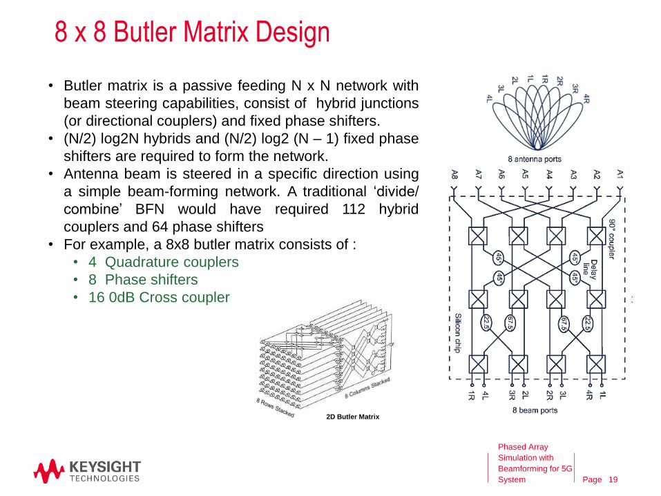
8 x 8 Butler Matrix Design
• Butler matrix is a passive feeding N x N network with
beam steering capabilities, consist of hybrid junctions
(or directional couplers) and fixed phase shifters.
• (N/2) log2N hybrids and (N/2) log2 (N – 1) fixed phase
shifters are required to form the network.
• Antenna beam is steered in a specific direction using
a simple beam-forming network. A traditional ‘divide/
combine’ BFN would have required 112 hybrid
couplers and 64 phase shifters
• For example, a 8x8 butler matrix consists of :
• 4 Quadrature couplers
• 8 Phase shifters
• 16 0dB Cross coupler
2D Butler Matrix
Phased Array
Simulation with
Beamforming for 5G
System 19
Page
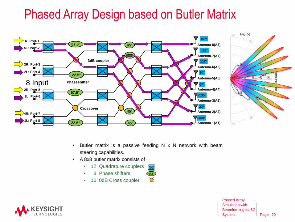
67.5°
22.5°
67.5°
22.5°
45°
45°
45°
45°
1R: Port-1
4L: Port-2
3R: Port-3
2L: Port-4
2R: Port-5
3L: Port-6
4R: Port-7
1L: Port-8
3dB coupler
Crossover
Phaseshifter
Antenna-8(A8)
Antenna-7(A7)
Antenna-6(A6)
Antenna-5(A5)
Antenna-4(A4)
Antenna-3(A3)
Antenna-2(A2)
Antenna-1(A1)
112°
90°
67°
-135°
22°
-180°
157°
-45°
• Butler matrix is a passive feeding N x N network with beam
steering capabilities.
• A 8x8 butler matrix consists of :
• 12 Quadrature couplers
• 8 Phase shifters
• 16 0dB Cross coupler
8 Input
Phased Array Design based on Butler Matrix
Phased Array
Simulation with
Beamforming for 5G
System 20

Page
27 mm
22 mm
22 mmBeam Orientation for Different Inputs
3D Beamforming Network
Phased Array
Simulation with
Beamforming for 5G
System 21
Page
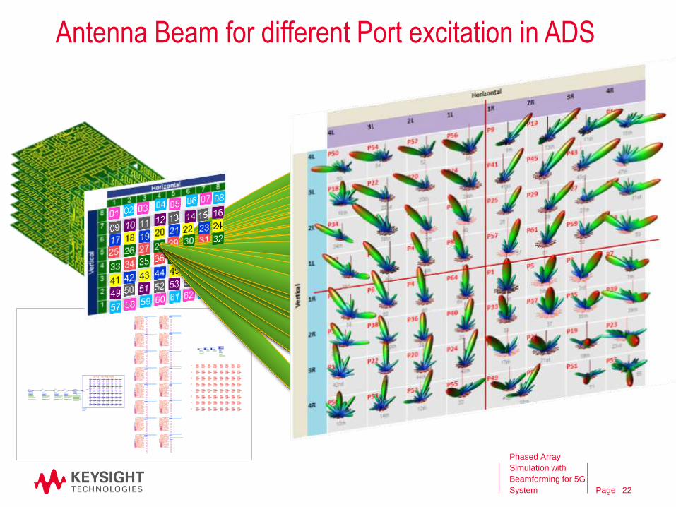
Antenna Beam for different Port excitation in ADS
Phased Array
Simulation with
Beamforming for 5G
System 22
Page
Agenda
• 5G and Phased Array System
• Phased Array Design Flow
• Pre-layout Simulation
SystemVue: 5G Phased Array System
• Post-layout Simulation
ADS: Butler Matrix Design
EMPro: Antenna Design
• Summary
23
Phased Array
Simulation with
Beamforming for 5G
System
Page
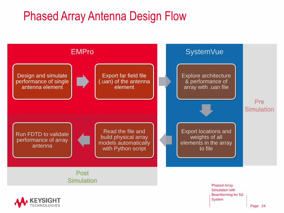
Phased Array Antenna Design Flow
SystemVueEMPro
Design and simulate performance of single
antenna element
Export far field file (.uan) of the antenna
element
Explore architecture & performance of array with .uan file
Export locations and weights of all
elements in the array to file
Read the file and build physical array
models automatically with Python script
Run FDTD to validate performance of array
antenna
Pre
Simulation
Post
SimulationPhased Array
Simulation with
Beamforming for 5G
System
24
Page
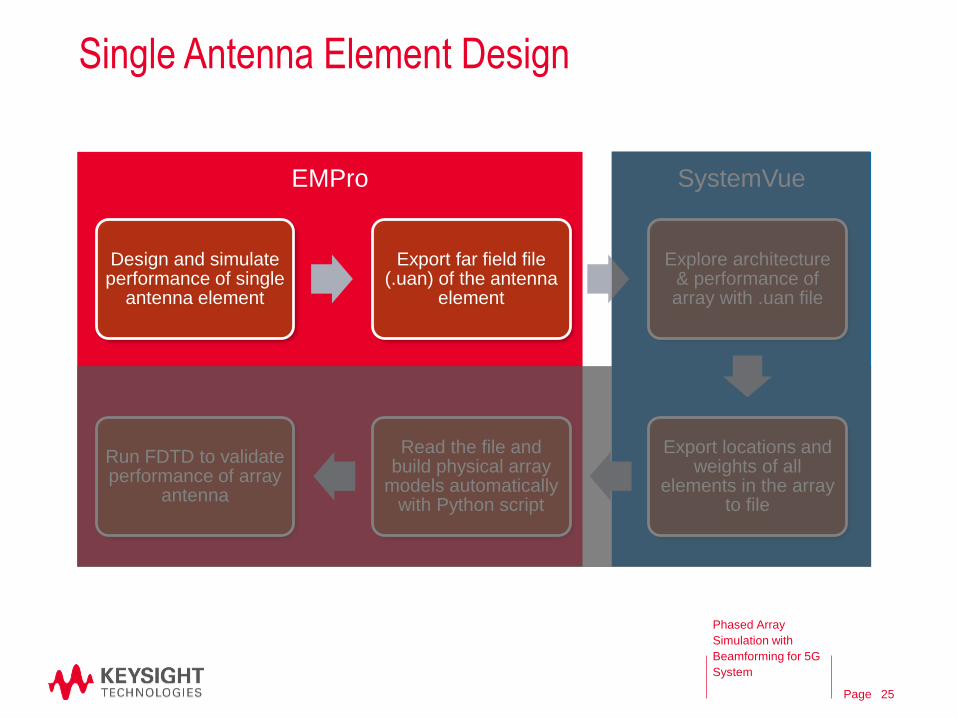
Single Antenna Element Design
SystemVueEMPro
Design and simulate performance of single
antenna element
Export far field file (.uan) of the antenna
element
Explore architecture & performance of array with .uan file
Export locations and weights of all
elements in the array to file
Read the file and build physical array
models automatically with Python script
Run FDTD to validate performance of array
antenna
Phased Array
Simulation with
Beamforming for 5G
System
25
Page
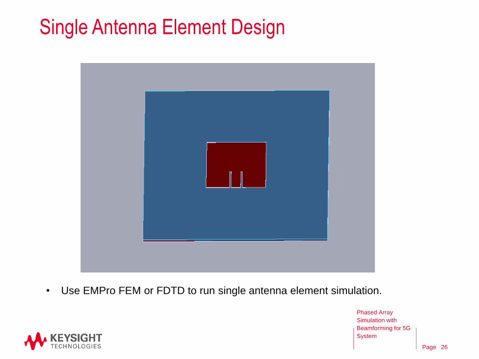
Single Antenna Element Design
• Use EMPro FEM or FDTD to run single antenna element simulation.
Phased Array
Simulation with
Beamforming for 5G
System
26
Page
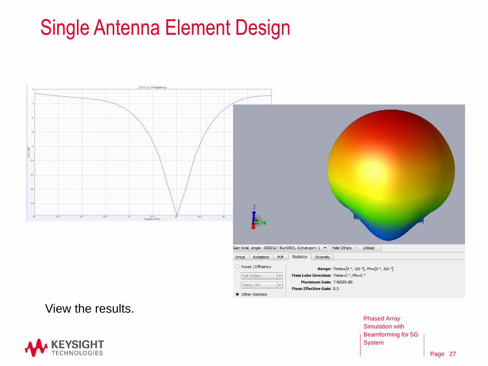
Single Antenna Element Design
View the results.Phased Array
Simulation with
Beamforming for 5G
System
27
Page
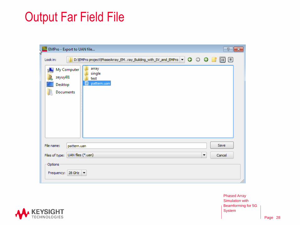
Output Far Field File
Phased Array
Simulation with
Beamforming for 5G
System
28
Page
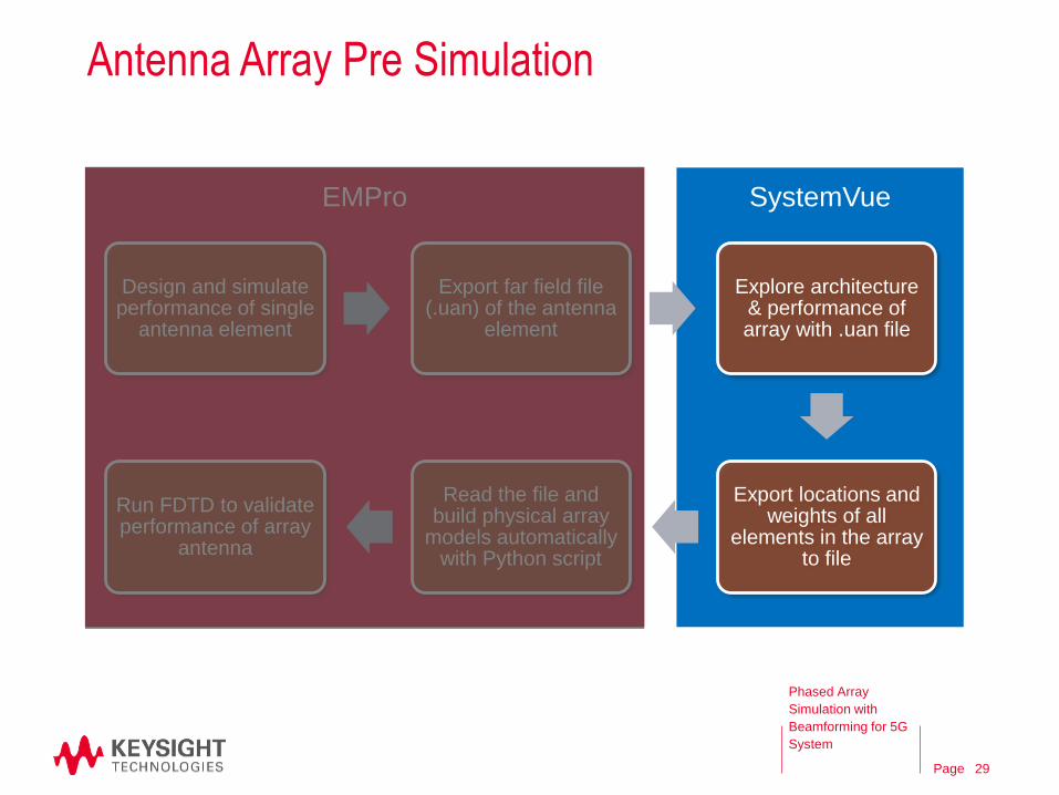
Antenna Array Pre Simulation
SystemVueEMPro
Design and simulate performance of single
antenna element
Export far field file (.uan) of the antenna
element
Explore architecture & performance of array with .uan file
Export locations and weights of all
elements in the array to file
Read the file and build physical array
models automatically with Python script
Run FDTD to validate performance of array
antenna
Phased Array
Simulation with
Beamforming for 5G
System
29

Page
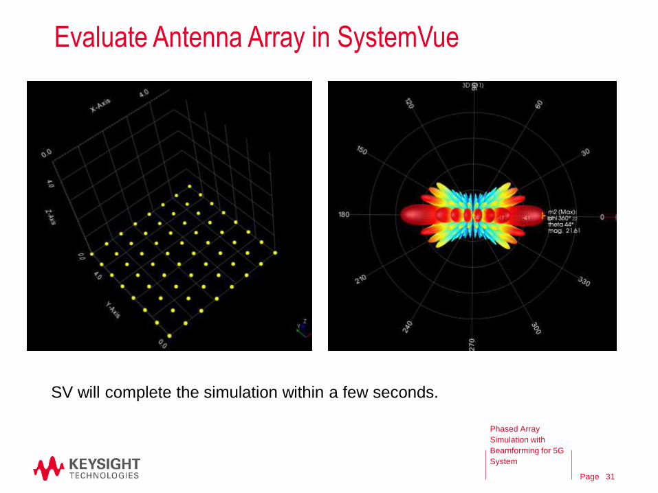
Evaluate Antenna Array in SystemVue
• For example, we want an 8*8 rectangular array with main lobe direction theta 45
degree + phi 0 degree.
• The distance between every element is set to be 0.7 lamda.
Phased Array
Simulation with
Beamforming for 5G
System
Main lobe direction setting
Weigh computing
component
Location and weight
information collecting
component
Pattern file loading
component
30
Page
Evaluate Antenna Array in SystemVue
SV will complete the simulation within a few seconds.
Phased Array
Simulation with
Beamforming for 5G
System
31
Page
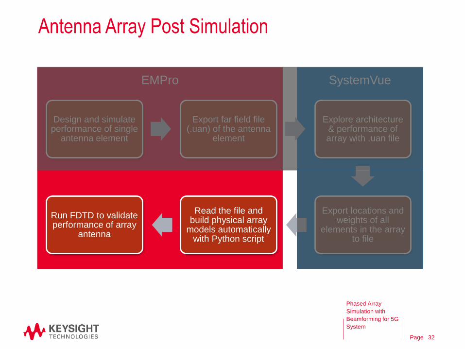
Antenna Array Post Simulation
SystemVueEMPro
Design and simulate performance of single
antenna element
Export far field file (.uan) of the antenna
element
Explore architecture & performance of array with .uan file
Export locations and weights of all
elements in the array to file
Read the file and build physical array
models automatically with Python script
Run FDTD to validate performance of array
antenna
Phased Array
Simulation with
Beamforming for 5G
System
32
Page
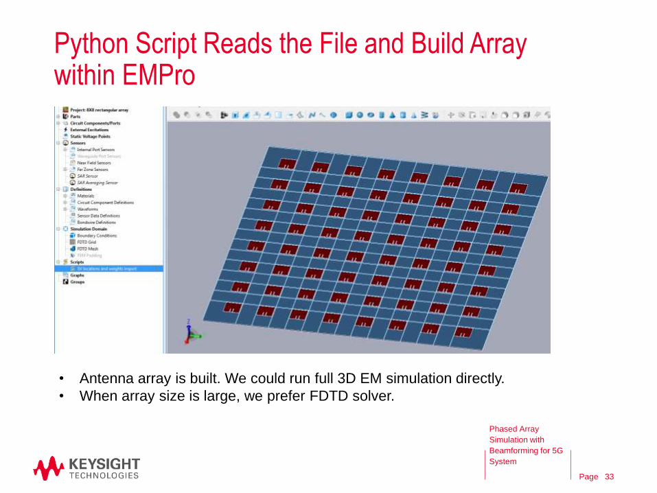
Python Script Reads the File and Build Array within EMPro
• Antenna array is built. We could run full 3D EM simulation directly.
• When array size is large, we prefer FDTD solver.
Phased Array
Simulation with
Beamforming for 5G
System
33
Page
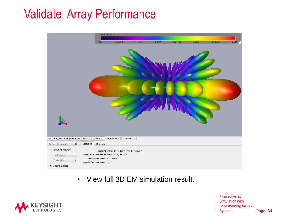
Validate Array Performance
34
• View full 3D EM simulation result.
Phased Array
Simulation with
Beamforming for 5G
System
Page
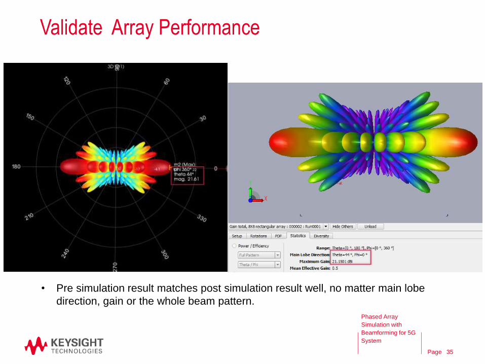
Validate Array Performance
• Pre simulation result matches post simulation result well, no matter main lobe
direction, gain or the whole beam pattern.
Phased Array
Simulation with
Beamforming for 5G
System
35
Page
More Validation
36
Phased Array
Simulation with
Beamforming for 5G
System
Page
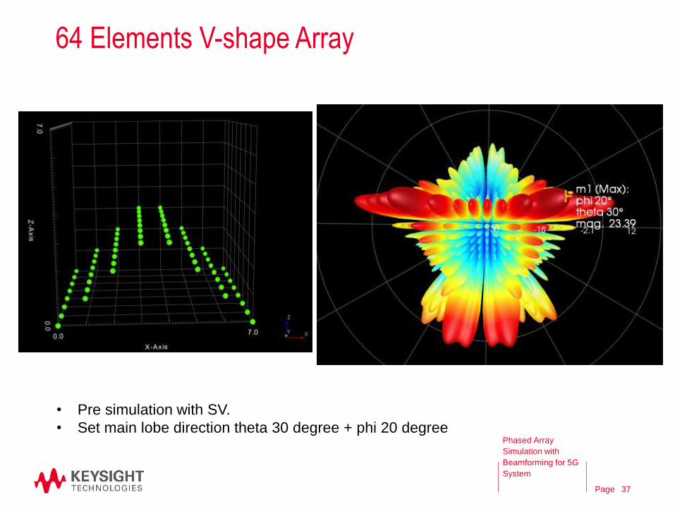
64 Elements V-shape Array
• Pre simulation with SV.
• Set main lobe direction theta 30 degree + phi 20 degreePhased Array
Simulation with
Beamforming for 5G
System
37
Page
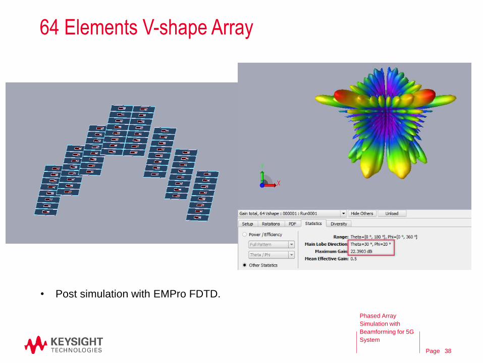
64 Elements V-shape Array
• Post simulation with EMPro FDTD.
Phased Array
Simulation with
Beamforming for 5G
System
38
Page
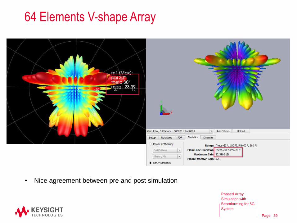
64 Elements V-shape Array
• Nice agreement between pre and post simulation
Phased Array
Simulation with
Beamforming for 5G
System
39
Page
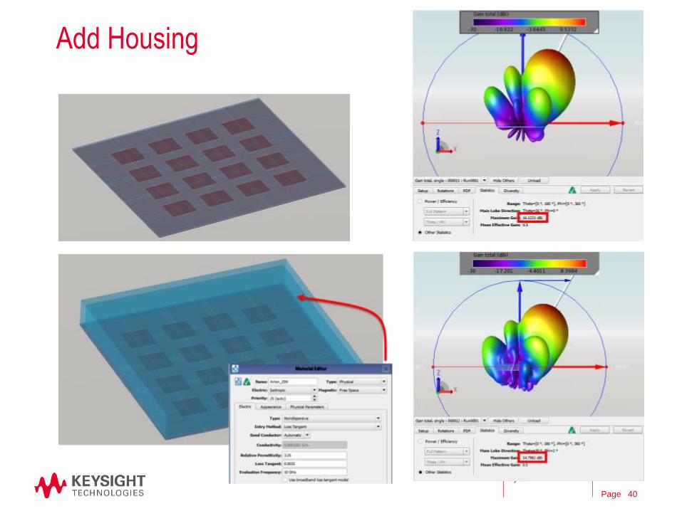
Add Housing
Phased Array
Simulation with
Beamforming for 5G
System
40
Page
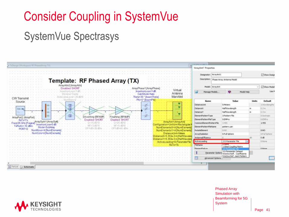
Consider Coupling in SystemVue
Phased Array
Simulation with
Beamforming for 5G
System
SystemVue Spectrasys
41
Page
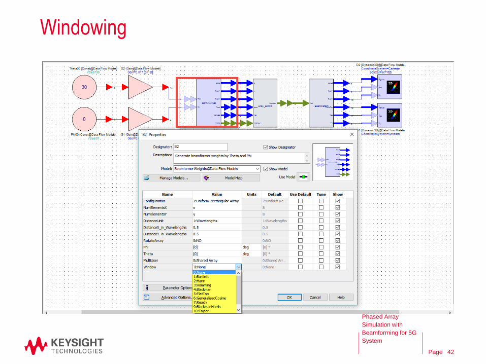
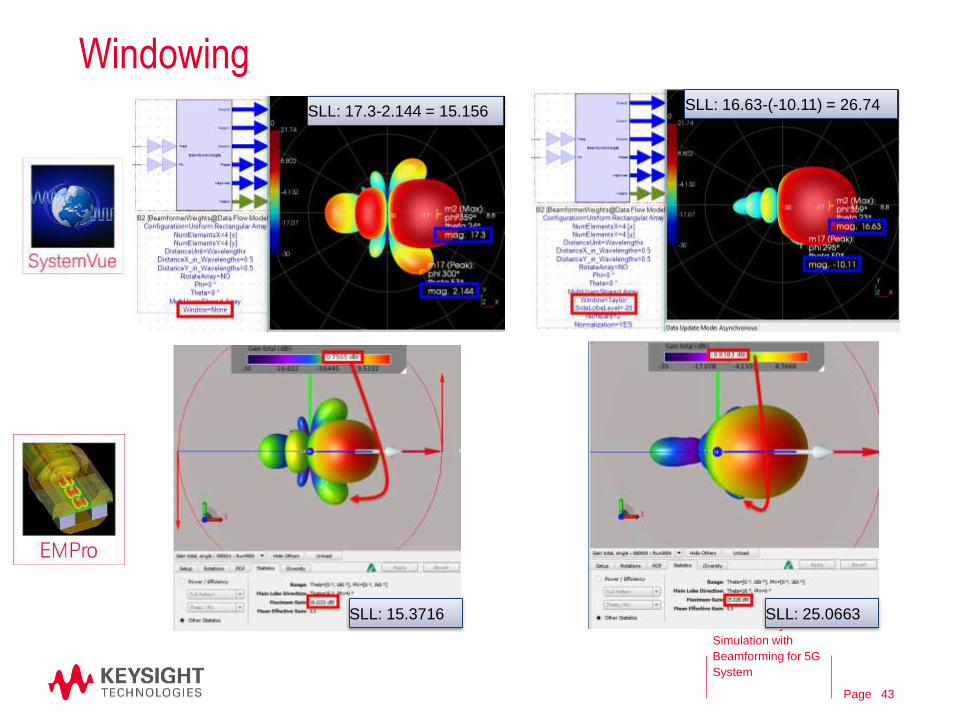
Windowing
Phased Array
Simulation with
Beamforming for 5G
System
42
Page
Windowing
Phased Array
Simulation with
Beamforming for 5G
System
SLL: 17.3-2.144 = 15.156 SLL: 16.63-(-10.11) = 26.74
SLL: 15.3716 SLL: 25.0663
43
Page
Agenda
• 5G and Phased Array System
• Phased Array Design Flow
• Pre-layout Simulation
SystemVue: 5G Phased Array System
• Post-layout Simulation
ADS: Butler Matrix Design
EMPro: Antenna Design
• Summary
44
Phased Array
Simulation with
Beamforming for 5G
System
Page
Summary
– Beamforming plays an important role in 5G system.
– Keysight offers a smooth phased array simulation flow with ADS,
EMPro, and SystemVue.
45
Phased Array
Simulation with
Beamforming for 5G
System