permagraph c - magnet-physik.de · 1 electromagnet ep 3 2 poles p 0/0 - ⌀ 92 mm 1 flat measuring...
TRANSCRIPT
www.magnet-physik.de Page 1 / 16
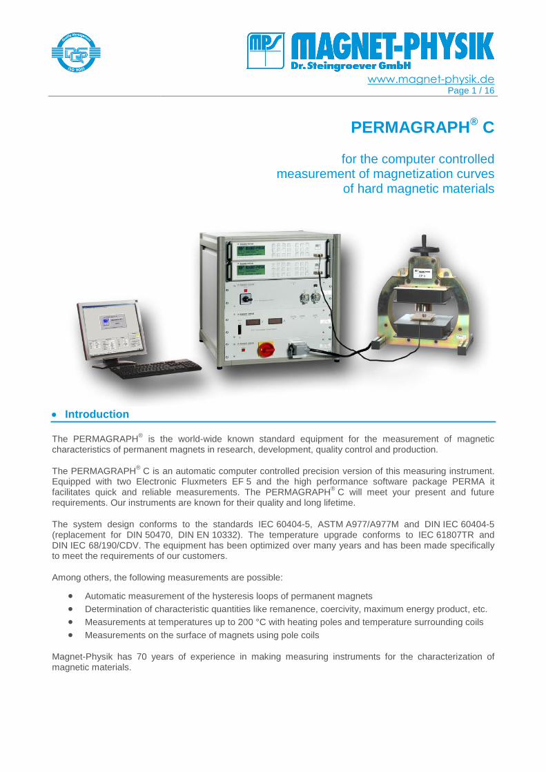
PERMAGRAPH® C
for the computer controlled
measurement of magnetization curves of hard magnetic materials
Introduction
The PERMAGRAPH® is the world-wide known standard equipment for the measurement of magnetic
characteristics of permanent magnets in research, development, quality control and production.
The PERMAGRAPH® C is an automatic computer controlled precision version of this measuring instrument.
Equipped with two Electronic Fluxmeters EF 5 and the high performance software package PERMA it facilitates quick and reliable measurements. The PERMAGRAPH
® C will meet your present and future
requirements. Our instruments are known for their quality and long lifetime.
The system design conforms to the standards IEC 60404-5, ASTM A977/A977M and DIN IEC 60404-5 (replacement for DIN 50470, DIN EN 10332). The temperature upgrade conforms to IEC 61807TR and DIN IEC 68/190/CDV. The equipment has been optimized over many years and has been made specifically to meet the requirements of our customers.
Among others, the following measurements are possible:
Automatic measurement of the hysteresis loops of permanent magnets
Determination of characteristic quantities like remanence, coercivity, maximum energy product, etc.
Measurements at temperatures up to 200 °C with heating poles and temperature surrounding coils
Measurements on the surface of magnets using pole coils
Magnet-Physik has 70 years of experience in making measuring instruments for the characterization of magnetic materials.
www.magnet-physik.de Page 2 / 16
Applications
Depending on the model of the PERMAGRAPH
® C and its particular accessories the following
measurements are possible:
Measurements on AlNiCo, Ferrite or Rare Earth magnets (e.g. Sm-Co or Nd-Fe-B) using J-compensated surrounding coils.
Measurements on Ferrite magnets using measuring poles with embedded pole coils.
Important: For the saturation of rare earth magnets an impulse magnetizer and a magnetization coil are required.
Measurement of Ferrite segment magnets with segment poles with incorporated pole coils, the poles are shaped corresponding to the radii of the segment magnet.
Measurement of AlNiCo, Ferrite or Rare earth magnets at high temperatures with up to 200 °C heatable poles and temperature resistant J-compensated surrounding coils.
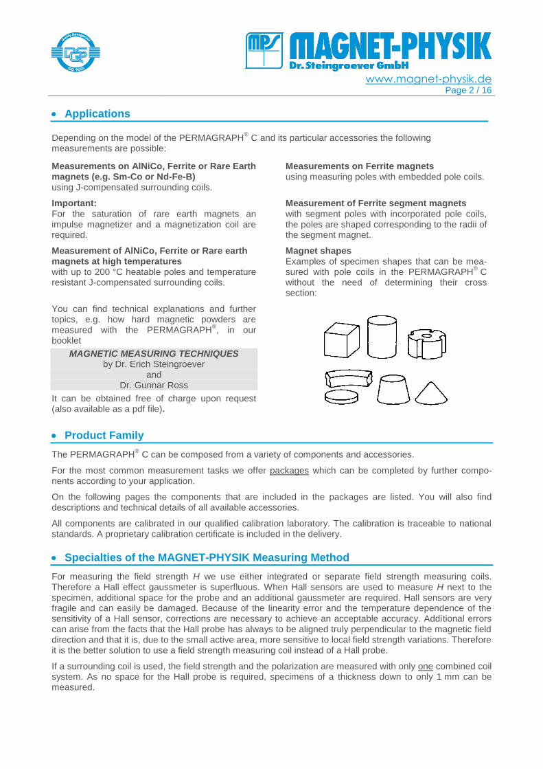
Magnet shapes Examples of specimen shapes that can be mea-sured with pole coils in the PERMAGRAPH
® C
without the need of determining their cross section:
You can find technical explanations and further topics, e.g. how hard magnetic powders are measured with the PERMAGRAPH
®, in our
booklet
MAGNETIC MEASURING TECHNIQUES by Dr. Erich Steingroever
and Dr. Gunnar Ross
It can be obtained free of charge upon request (also available as a pdf file).
Product Family
The PERMAGRAPH® C can be composed from a variety of components and accessories.
For the most common measurement tasks we offer packages which can be completed by further compo-nents according to your application.
On the following pages the components that are included in the packages are listed. You will also find descriptions and technical details of all available accessories.
All components are calibrated in our qualified calibration laboratory. The calibration is traceable to national standards. A proprietary calibration certificate is included in the delivery.
Specialties of the MAGNET-PHYSIK Measuring Method
For measuring the field strength H we use either integrated or separate field strength measuring coils. Therefore a Hall effect gaussmeter is superfluous. When Hall sensors are used to measure H next to the specimen, additional space for the probe and an additional gaussmeter are required. Hall sensors are very fragile and can easily be damaged. Because of the linearity error and the temperature dependence of the sensitivity of a Hall sensor, corrections are necessary to achieve an acceptable accuracy. Additional errors can arise from the facts that the Hall probe has always to be aligned truly perpendicular to the magnetic field direction and that it is, due to the small active area, more sensitive to local field strength variations. Therefore it is the better solution to use a field strength measuring coil instead of a Hall probe.
If a surrounding coil is used, the field strength and the polarization are measured with only one combined coil system. As no space for the Hall probe is required, specimens of a thickness down to only 1 mm can be measured.
www.magnet-physik.de Page 3 / 16
Packages, Upgrades and Options
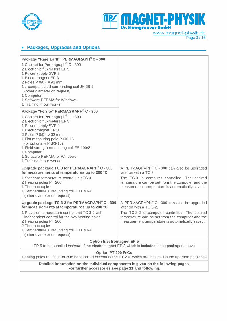
Package “Rare Earth” PERMAGRAPH C - 300
1 Cabinet for Permagraph® C - 300
2 Electronic fluxmeters EF 5 1 Power supply SVP 2 1 Electromagnet EP 3 2 Poles P 0/0 - ⌀ 92 mm 1 J-compensated surrounding coil JH 26-1
(other diameter on request) 1 Computer 1 Software PERMA for Windows 1 Training in our works
Package “Ferrite” PERMAGRAPH C - 300
1 Cabinet for Permagraph® C - 300
2 Electronic fluxmeters EF 5 1 Power supply SVP 2 1 Electromagnet EP 3
2 Poles P 0/0 - ⌀ 92 mm 1 Flat measuring pole P 6/6-15
(or optionally P 3/3-15) 1 Field strength measuring coil FS 100/2 1 Computer 1 Software PERMA for Windows 1 Training in our works
Upgrade package TC 3 for PERMAGRAPH C - 300
for measurements at temperatures up to 200 °C
1 Standard temperature control unit TC 3 2 Heating poles PT 200 1 Thermocouple 1 Temperature surrounding coil JHT 40-4
(other diameter on request)
A PERMAGRAPH C - 300 can also be upgraded later on with a TC 3.
The TC 3 is computer controlled. The desired temperature can be set from the computer and the measurement temperature is automatically saved.
Upgrade package TC 3-2 for PERMAGRAPH C - 300
for measurements at temperatures up to 200 °C
1 Precision temperature control unit TC 3-2 with independent control for the two heating poles
2 Heating poles PT 200 2 Thermocouples 1 Temperature surrounding coil JHT 40-4
(other diameter on request)
A PERMAGRAPH C - 300 can also be upgraded later on with a TC 3-2.
The TC 3-2 is computer controlled. The desired temperature can be set from the computer and the measurement temperature is automatically saved.
Option Electromagnet EP 5 EP 5 to be supplied instead of the electromagnet EP 3 which is included in the packages above
Option PT 200 FeCo Heating poles PT 200 FeCo to be supplied instead of the PT 200 which are included in the upgrade packages
Detailed information on the individual components is given on the following pages. For further accessories see page 11 and following.
www.magnet-physik.de Page 4 / 16
Technical Data
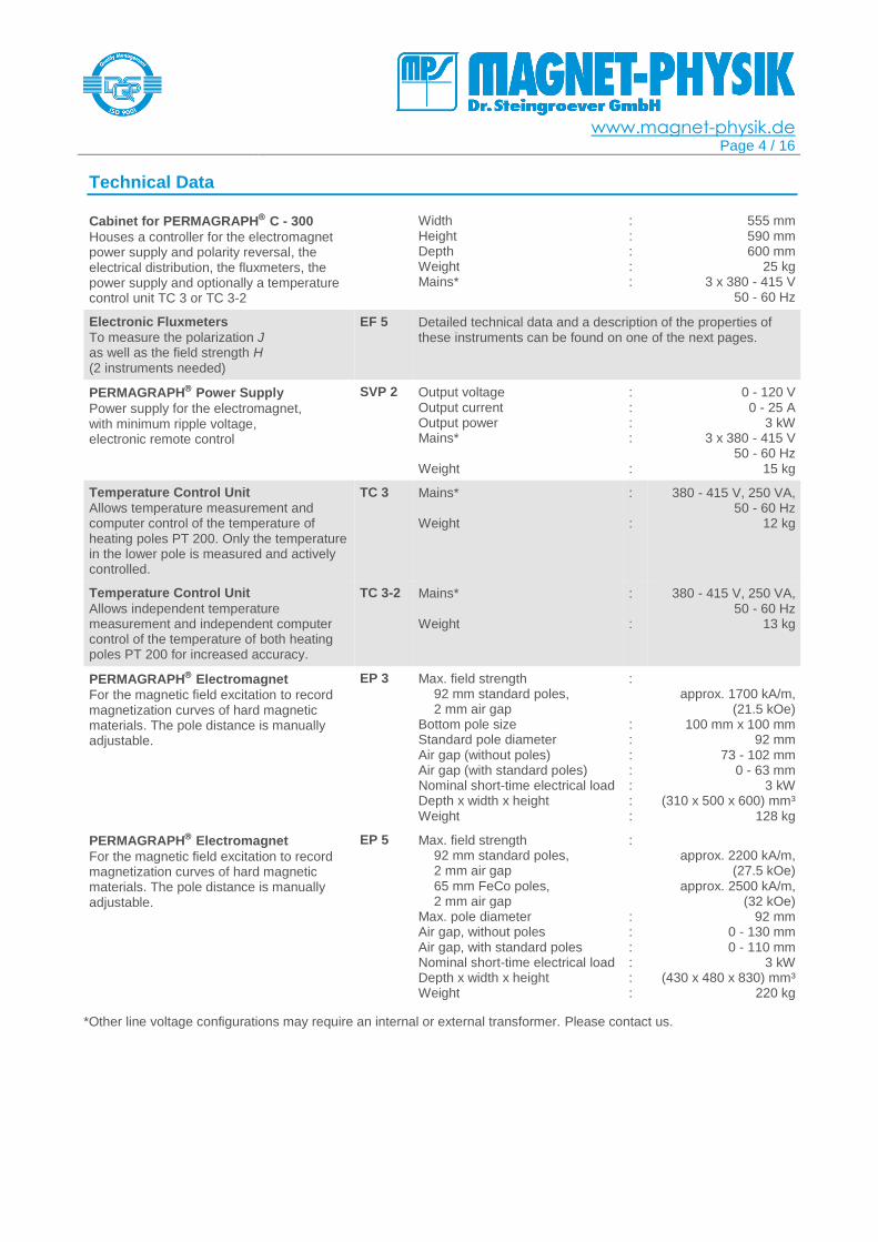
Cabinet for PERMAGRAPH C - 300
Houses a controller for the electromagnet power supply and polarity reversal, the electrical distribution, the fluxmeters, the power supply and optionally a temperature control unit TC 3 or TC 3-2
Width Height Depth Weight Mains*
: : : : :
555 mm 590 mm 600 mm
25 kg 3 x 380 - 415 V
50 - 60 Hz
Electronic Fluxmeters
To measure the polarization J as well as the field strength H (2 instruments needed)
EF 5 Detailed technical data and a description of the properties of these instruments can be found on one of the next pages.
PERMAGRAPH Power Supply
Power supply for the electromagnet, with minimum ripple voltage, electronic remote control
SVP 2 Output voltage Output current Output power Mains* Weight
: : : : :
0 - 120 V 0 - 25 A
3 kW 3 x 380 - 415 V
50 - 60 Hz 15 kg
Temperature Control Unit
Allows temperature measurement and computer control of the temperature of heating poles PT 200. Only the temperature in the lower pole is measured and actively controlled.
TC 3 Mains* Weight
: :
380 - 415 V, 250 VA, 50 - 60 Hz
12 kg
Temperature Control Unit
Allows independent temperature measurement and independent computer control of the temperature of both heating poles PT 200 for increased accuracy.
TC 3-2 Mains* Weight
: :
380 - 415 V, 250 VA, 50 - 60 Hz
13 kg
PERMAGRAPH Electromagnet
For the magnetic field excitation to record magnetization curves of hard magnetic materials. The pole distance is manually adjustable.
EP 3 Max. field strength 92 mm standard poles, 2 mm air gap
Bottom pole size Standard pole diameter Air gap (without poles) Air gap (with standard poles) Nominal short-time electrical load Depth x width x height Weight
: : : : : : : :
approx. 1700 kA/m,
(21.5 kOe) 100 mm x 100 mm
92 mm 73 - 102 mm
0 - 63 mm 3 kW
(310 x 500 x 600) mm³ 128 kg
PERMAGRAPH Electromagnet
For the magnetic field excitation to record magnetization curves of hard magnetic materials. The pole distance is manually adjustable.
EP 5 Max. field strength 92 mm standard poles, 2 mm air gap 65 mm FeCo poles, 2 mm air gap
Max. pole diameter Air gap, without poles Air gap, with standard poles Nominal short-time electrical load Depth x width x height Weight
: : : : : : :
approx. 2200 kA/m,
(27.5 kOe) approx. 2500 kA/m,
(32 kOe) 92 mm
0 - 130 mm 0 - 110 mm
3 kW (430 x 480 x 830) mm³
220 kg
*Other line voltage configurations may require an internal or external transformer. Please contact us.

www.magnet-physik.de Page 5 / 16
Operation
The PERMAGRAPH® can automatically record the demagnetization curves of permanent magnets. The
measuring method is standardized and verified by round robin tests.
Central component of the measuring instrument is an electromagnet that is used to magnetize and demagnetize the magnet specimen in order to cycle through the hysteresis loop. The magnetic field strength H and the magnetic polarization J are measured simultaneously with special measuring coils. Two integrators (fluxmeters) are required to process the output signals of the coils. The measuring coils and their parameters are automatically identified by the fluxmeters. The PERMAGRAPH
® C uses two EF 5 precision
fluxmeters with unique digitally compensated integrators.
The two fluxmeters are synchronously triggered. They are operated from a computer. The measured data are received from the two fluxmeters via digital interfaces and shown on the computer display in real-time. This allows checking the results already while the measuring procedure is in progress. The measuring process is controlled via a digital computer interface.
The computer also allows an evaluation and output of the measuring data, so that the measuring results are directly available.
Usually only the second quadrant of a hysteresis loop, the demagnetization curve, is of interest for the application of permanent magnets. Therefore the measurements can be automatically stopped after the coercivity HcJ is reached.
The measurement is carried out quasi-statically, which means that the demagnetization curve is recorded rather slowly, avoiding eddy current problems.
The specimen and measuring parameters can be stored. Thus in the case of new measurements only a few new inputs must be made.
Features of PERMA – Software for PERMAGRAPH®
Flexible, user friendly operation using menus, function keys and shortcut keys or icons Extensive help files, context-sensitive help Convenient input of measuring parameters Saving and opening of parameters and measuring data Multiple measurements can be simultaneously opened for easy comparison Existing measurements can serve as templates for new measurements Automatic calculation of measured results Automatic saving of measured data, parameters and results (e.g. under a test name or number) Saving of a group of associate measurements into a single file Export of measuring data, parameters and results to text files or to Microsoft Excel® files Export of parameters and results to text databases or SQL databases, a database viewer is
integrated in the software Print preview for measurement diagrams with curves, parameters and results Output of measurement diagrams to a printer or pdf writer (printer and pdf writer not included) Copying of measuring diagrams and result lists via the Windows® clipboard Saving measuring diagrams as pictures (bmp, gif, jpeg, png) for easy distribution Various possibilities for customer specific output design as selection of curves, calculated results,
units, measuring parameters, user-definable information texts, company logo, etc. User-definable limit classifiers for all results (out of range results are shown in red or boldface) Display of multiple curves in one diagram including results Optional display of averaged results of multiple measurements Different output diagram layouts can be saved for easy switching between different outputs Selectable units for magnetic quantities, temperatures, specimen dimensions and other parameters Full support of SI and CGS units in software and output, changing units is possible at any time Simultaneous display of results in mixed SI and CGS units can be configured by the user The number of significant digits to be displayed for results can be selected by the user Creating of result lists for multiple measurements incl. the possibility of saving, copying and printing Program menu access can be restricted for selected users (password protection)
www.magnet-physik.de Page 6 / 16
Language separately selectable for program menus and output (English, German, French, Spanish, Polish, Czech, Slovak, Russian, Chinese (simplified))
Microsoft Windows® Vista / 7 / 8 / 10 compatible
Parameters
Default parameters minimize the number of necessary inputs Automatic measuring coil type and coil data identification Calculation of the cross-sectional area from specimen geometries Input of measurement and specimen identification data to predefined or user-definable text lines Input of room and specimen temperatures in °C, °F or K Automatic room temperature recording with optional room temperature sensor Extensive parameter verification to avoid illegal or inconsistent parameter settings
Measurement
Magnetization and demagnetization curve or demagnetization curve only Drift correction: automatic or on command, reminder for drift correction by software if required Automatic polarity detection and adjustment of field direction for magnetized rare earth magnets Adjustable duration of measurement, usually 20 - 120 seconds depending on specimen type Speed enhancement by faster magnetization and sufficiently slow demagnetization Measuring speed: constant dI/dt or dJ/dt controlled Excitation to preset values of field current I, field strength H or polarization J Automatic stop at HcJ possible Automatic stop at -Imax possible
Curves
Demagnetization curve 2- or 4-quadrant hysteresis loop Recoil curves or inner (minor) loops, automatically or manual (BH)max area BH = const. hyperbolas B = 0 line
Evaluation
Remanence (Br or Jr) Coercivity of J(H) curve HcJ (intrinsic coercivity) Coercivity of B(H) curve HcB (normal coercivity) Maximum energy product (BH)max Maximum field strength Hmax Maximum polarization Jmax and Br/Jmax ratio Hk: knee shape parameter (H coordinate of J(H) curve for J = 0.9 · Br) Hx: H coordinate of J(H) curve for J = x · Br HD5 and HD2 results Tables of J(H) and B(H), where H are user defined field strengths Tables of H(J) and B(J), where J are user defined polarizations Tables of H(B) and J(B), where B are user defined flux densities (inductions) User values for tables can be predefined and stored. The corresponding functional values are
automatically interpolated. Output of specimen and measurement parameters and calculated results to ASCII text files,
Microsoft Excel® worksheets (xlsx) or Microsoft Excel® xml spreadsheets
Output of sample and measurement parameters and calculated results to databases Temperature correction: conversion of results by means of temperature coefficients of Br or HcJ
Microsoft Excel®, a SQL server and a PDF writer are not included.
www.magnet-physik.de Page 7 / 16
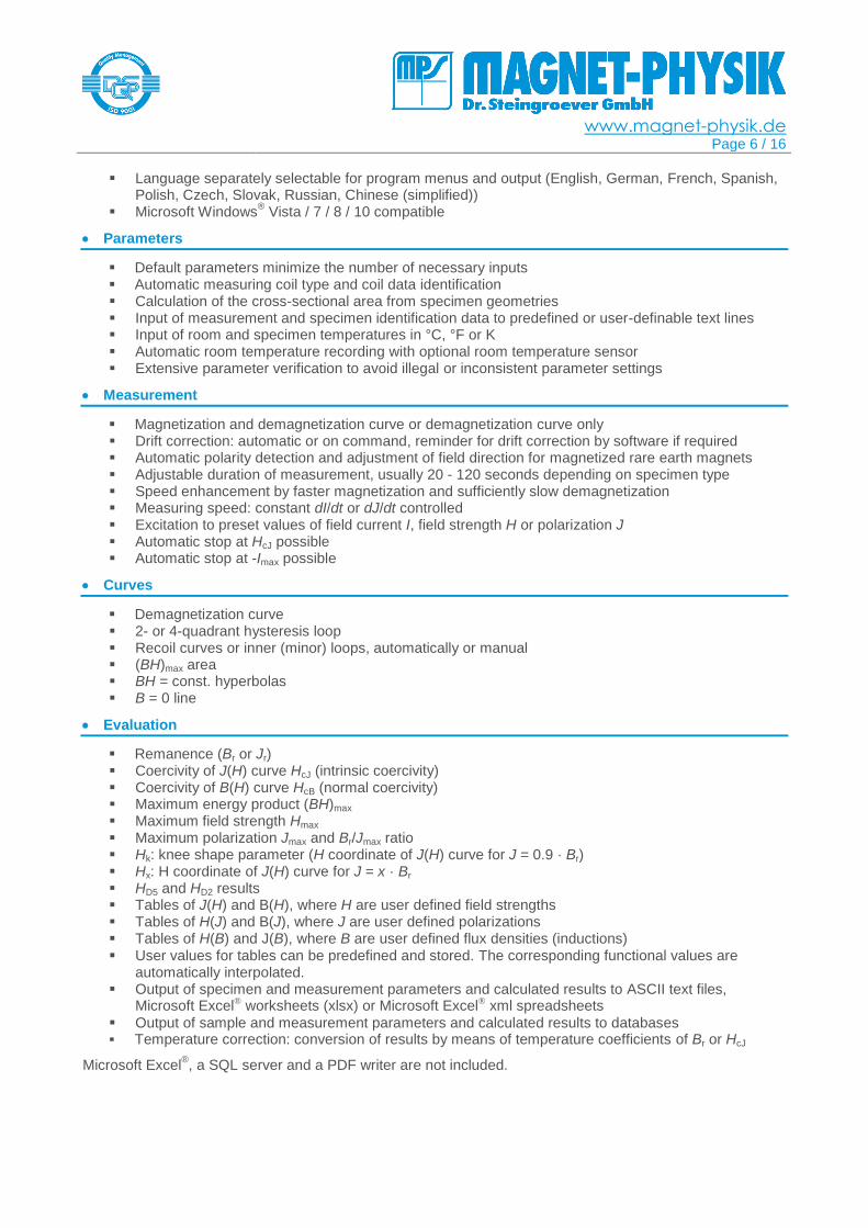
Screenshots
Main window with different measurements
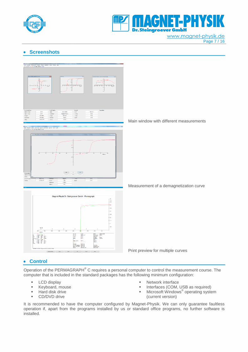
Measurement of a demagnetization curve
Print preview for multiple curves
Control
Operation of the PERMAGRAPH® C requires a personal computer to control the measurement course. The
computer that is included in the standard packages has the following minimum configuration:
LCD display Keyboard, mouse Hard disk drive CD/DVD drive
Network interface Interfaces (COM, USB as required) Microsoft Windows
® operating system
(current version)
It is recommended to have the computer configured by Magnet-Physik. We can only guarantee faultless operation if, apart from the programs installed by us or standard office programs, no further software is installed.
www.magnet-physik.de Page 8 / 16
Example Diagrams
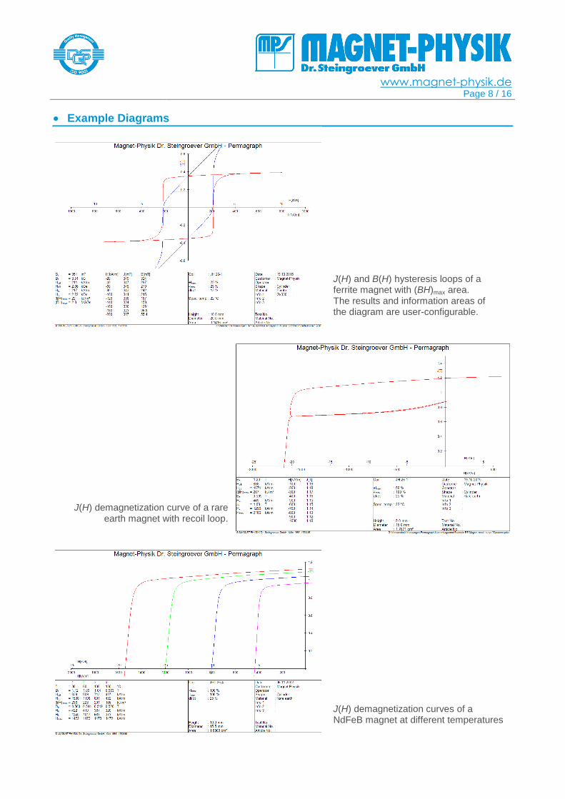
J(H) and B(H) hysteresis loops of a ferrite magnet with (BH)max area. The results and information areas of the diagram are user-configurable.
J(H) demagnetization curve of a rare earth magnet with recoil loop.
J(H) demagnetization curves of a NdFeB magnet at different temperatures
www.magnet-physik.de Page 9 / 16
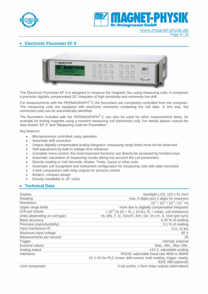
Electronic Fluxmeter EF 5
The Electronic Fluxmeter EF 5 is designed to measure the magnetic flux using measuring coils. It comprises a precision digitally compensated DC integrator of high sensitivity and extremely low drift.
For measurements with the PERMAGRAPH® C the fluxmeters are completely controlled from the computer.
The measuring coils are equipped with electronic memories containing the coil data. In this way, the connected coils can be automatically identified.
The fluxmeters included with the PERMAGRAPH® C can also be used for other measurement tasks, for
example for testing magnets using a moment measuring coil (Helmholtz coil). For details please consult the data sheets “EF 5” and “Measuring Coils for Fluxmeters”.
Key features:
Microprocessor controlled, easy operation
Automatic drift correction
Unique digitally compensated analog integrator: measuring range limits must not be observed
Self-adjustment by built-in voltage-time reference
Complete menu control, the most important functions can directly be accessed by function keys
Automatic calculation of measuring results taking into account the coil parameters
Directly reading in Volt-Seconds, Weber, Tesla, Gauss or other units
Automatic coil recognition and instrument configuration for measuring coils with data memories
4 limit comparators with relay outputs for process control
Modern, compact design
Directly installable to 19" racks
Technical Data
Display backlight LCD, 122 x 41 mm²
Reading max. 6 digits plus 2 digits for exponent
Resolution 10-4
/ 10-5
/ 10-6
/ 10-7
Vs
Upper range limits none due to digitally compensated integrator
Drift per minute < 10-6
Vs (Ri + Rs 10 k, Rs = meas. coil resistance)
Units (depending on coil type) Vs, Wb, T, G, Vs/cm², A/m, Oe, Vs cm, A, Vs/n (per turn)
Basic accuracy 0.25 % of reading
Precision (reproducibility) 0.1 % of reading
Input resistances Ri 0 , 10 k
Maximum input voltage 60 V
Measurements per second 25
Trigger internal, external
Extreme values Max., Min., Max.-Min.
Analog output ±10 V, adjustable scaling
Interfaces RS232, adjustable baud rate 4800 to 38400 24 V I/O for PLC (reset, drift control, hold reading, trigger, ready)
IEEE 488 (optional)
Limit comparator 4 trip points, c-form relay outputs (alternators)
www.magnet-physik.de Page 10 / 16
Electromagnets
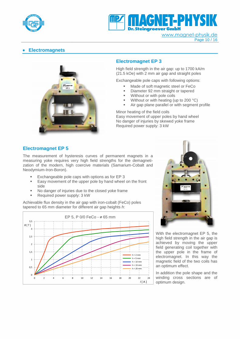
Electromagnet EP 3
High field strength in the air gap: up to 1700 kA/m (21.5 kOe) with 2 mm air gap and straight poles
Exchangeable pole caps with following options:
Made of soft magnetic steel or FeCo Diameter 92 mm straight or tapered Without or with pole coils Without or with heating (up to 200 °C) Air gap plane parallel or with segment profile
Minor heating of the field coils Easy movement of upper poles by hand wheel No danger of injuries by skewed yoke frame Required power supply: 3 kW
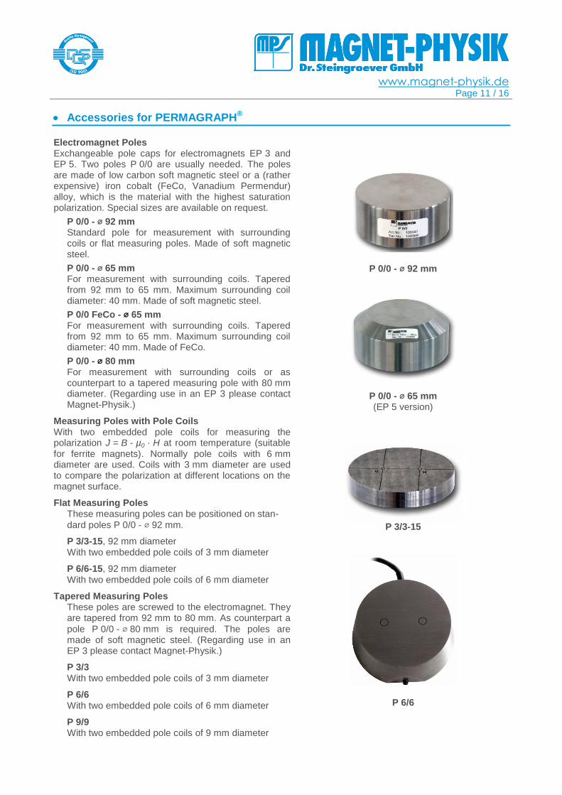
Electromagnet EP 5
The measurement of hysteresis curves of permanent magnets in a measuring yoke requires very high field strengths for the demagneti-zation of the modern, high coercive materials (Samarium-Cobalt and Neodymium-Iron-Boron).
Exchangeable pole caps with options as for EP 3 Easy movement of the upper pole by hand wheel on the front
side No danger of injuries due to the closed yoke frame Required power supply: 3 kW
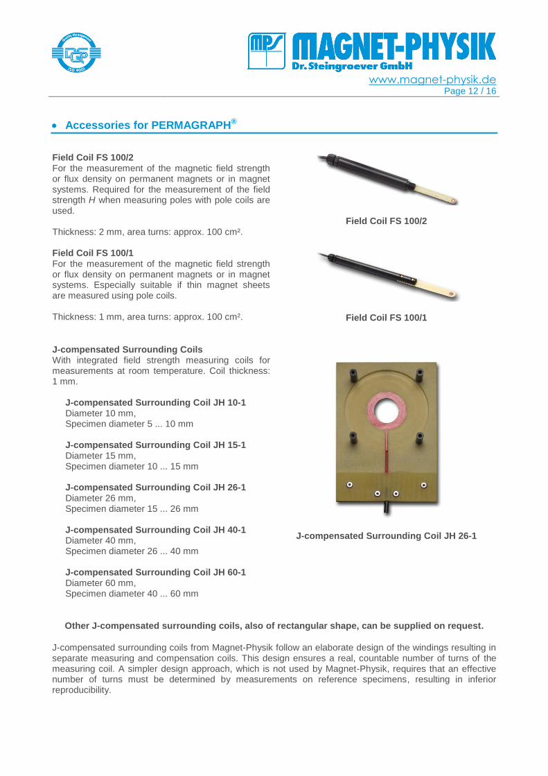
Achievable flux density in the air gap with iron-cobalt (FeCo) poles tapered to 65 mm diameter for different air gap heights h:
With the electromagnet EP 5, the high field strength in the air gap is achieved by moving the upper field generating coil together with the upper pole in the frame of electromagnet. In this way the magnetic field of the two coils has an optimum effect.
In addition the pole shape and the winding cross sections are of optimum design.
0
0,5
1
1,5
2
2,5
3
3,5
0 2 4 6 8 10 12 14 16 18 20 22 24
B [ T ]
I [ A ]
EP 5, P 0/0 FeCo - ⌀ 65 mm
h = 2 mm
h = 5 mm
h = 10 mm
h = 15 mm
h = 20 mm
www.magnet-physik.de Page 11 / 16
Accessories for PERMAGRAPH®
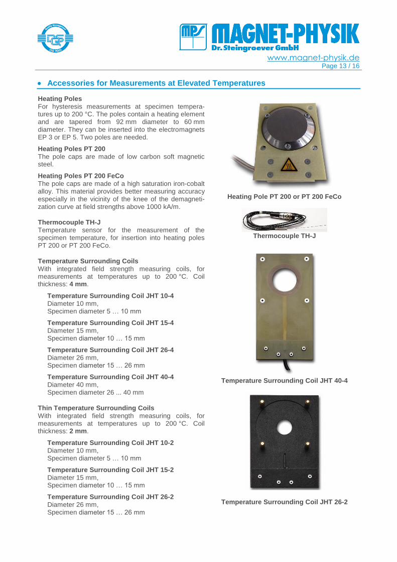
Electromagnet Poles Exchangeable pole caps for electromagnets EP 3 and EP 5. Two poles P 0/0 are usually needed. The poles are made of low carbon soft magnetic steel or a (rather expensive) iron cobalt (FeCo, Vanadium Permendur) alloy, which is the material with the highest saturation polarization. Special sizes are available on request.
P 0/0 - ⌀ 92 mm Standard pole for measurement with surrounding coils or flat measuring poles. Made of soft magnetic steel.
P 0/0 - ⌀ 65 mm For measurement with surrounding coils. Tapered from 92 mm to 65 mm. Maximum surrounding coil diameter: 40 mm. Made of soft magnetic steel.
P 0/0 FeCo - ⌀ 65 mm For measurement with surrounding coils. Tapered from 92 mm to 65 mm. Maximum surrounding coil diameter: 40 mm. Made of FeCo.
P 0/0 - ⌀ 80 mm For measurement with surrounding coils or as counterpart to a tapered measuring pole with 80 mm diameter. (Regarding use in an EP 3 please contact Magnet-Physik.)
Measuring Poles with Pole Coils With two embedded pole coils for measuring the polarization J = B - µ0 · H at room temperature (suitable for ferrite magnets). Normally pole coils with 6 mm diameter are used. Coils with 3 mm diameter are used to compare the polarization at different locations on the magnet surface.
Flat Measuring Poles These measuring poles can be positioned on stan-
dard poles P 0/0 - ⌀ 92 mm.
P 3/3-15, 92 mm diameter With two embedded pole coils of 3 mm diameter
P 6/6-15, 92 mm diameter With two embedded pole coils of 6 mm diameter
Tapered Measuring Poles These poles are screwed to the electromagnet. They are tapered from 92 mm to 80 mm. As counterpart a
pole P 0/0 - ⌀ 80 mm is required. The poles are made of soft magnetic steel. (Regarding use in an EP 3 please contact Magnet-Physik.)
P 3/3 With two embedded pole coils of 3 mm diameter
P 6/6 With two embedded pole coils of 6 mm diameter
P 9/9 With two embedded pole coils of 9 mm diameter
P 0/0 - ⌀ 92 mm
P 0/0 - ⌀ 65 mm (EP 5 version)
P 3/3-15
P 6/6
www.magnet-physik.de Page 12 / 16
Accessories for PERMAGRAPH®
Field Coil FS 100/2 For the measurement of the magnetic field strength or flux density on permanent magnets or in magnet systems. Required for the measurement of the field strength H when measuring poles with pole coils are used. Thickness: 2 mm, area turns: approx. 100 cm².
Field Coil FS 100/2
Field Coil FS 100/1 For the measurement of the magnetic field strength or flux density on permanent magnets or in magnet systems. Especially suitable if thin magnet sheets are measured using pole coils. Thickness: 1 mm, area turns: approx. 100 cm².
Field Coil FS 100/1
J-compensated Surrounding Coils With integrated field strength measuring coils for measurements at room temperature. Coil thickness: 1 mm.
J-compensated Surrounding Coil JH 10-1 Diameter 10 mm, Specimen diameter 5 ... 10 mm J-compensated Surrounding Coil JH 15-1 Diameter 15 mm, Specimen diameter 10 ... 15 mm J-compensated Surrounding Coil JH 26-1 Diameter 26 mm, Specimen diameter 15 ... 26 mm J-compensated Surrounding Coil JH 40-1 Diameter 40 mm, Specimen diameter 26 ... 40 mm J-compensated Surrounding Coil JH 60-1 Diameter 60 mm, Specimen diameter 40 ... 60 mm
J-compensated Surrounding Coil JH 26-1
Other J-compensated surrounding coils, also of rectangular shape, can be supplied on request.
J-compensated surrounding coils from Magnet-Physik follow an elaborate design of the windings resulting in separate measuring and compensation coils. This design ensures a real, countable number of turns of the measuring coil. A simpler design approach, which is not used by Magnet-Physik, requires that an effective number of turns must be determined by measurements on reference specimens, resulting in inferior reproducibility.
www.magnet-physik.de Page 13 / 16
Accessories for Measurements at Elevated Temperatures
Heating Poles For hysteresis measurements at specimen tempera-tures up to 200 °C. The poles contain a heating element and are tapered from 92 mm diameter to 60 mm diameter. They can be inserted into the electromagnets EP 3 or EP 5. Two poles are needed.
Heating Poles PT 200 The pole caps are made of low carbon soft magnetic steel.
Heating Poles PT 200 FeCo The pole caps are made of a high saturation iron-cobalt alloy. This material provides better measuring accuracy especially in the vicinity of the knee of the demagneti-zation curve at field strengths above 1000 kA/m.
Thermocouple TH-J Temperature sensor for the measurement of the specimen temperature, for insertion into heating poles PT 200 or PT 200 FeCo.
Temperature Surrounding Coils With integrated field strength measuring coils, for measurements at temperatures up to 200 °C. Coil thickness: 4 mm.
Temperature Surrounding Coil JHT 10-4 Diameter 10 mm, Specimen diameter 5 … 10 mm
Temperature Surrounding Coil JHT 15-4 Diameter 15 mm, Specimen diameter 10 … 15 mm
Temperature Surrounding Coil JHT 26-4 Diameter 26 mm, Specimen diameter 15 … 26 mm
Temperature Surrounding Coil JHT 40-4 Diameter 40 mm, Specimen diameter 26 ... 40 mm
Thin Temperature Surrounding Coils With integrated field strength measuring coils, for measurements at temperatures up to 200 °C. Coil thickness: 2 mm.
Temperature Surrounding Coil JHT 10-2 Diameter 10 mm, Specimen diameter 5 … 10 mm
Temperature Surrounding Coil JHT 15-2 Diameter 15 mm, Specimen diameter 10 … 15 mm
Temperature Surrounding Coil JHT 26-2 Diameter 26 mm, Specimen diameter 15 … 26 mm
Heating Pole PT 200 or PT 200 FeCo
Thermocouple TH-J
Temperature Surrounding Coil JHT 40-4
Temperature Surrounding Coil JHT 26-2
www.magnet-physik.de Page 14 / 16
Special Applications
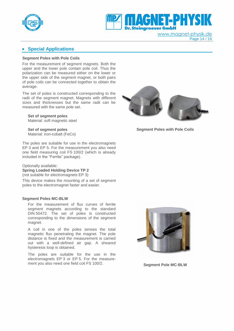
Segment Poles with Pole Coils
For the measurement of segment magnets. Both the upper and the lower pole contain pole coil. Thus the polarization can be measured either on the lower or the upper side of the segment magnet, or both pairs of pole coils can be connected together to obtain the average.
The set of poles is constructed corresponding to the radii of the segment magnet. Magnets with different sizes and thicknesses but the same radii can be measured with the same pole set.
Set of segment poles Material: soft magnetic steel Set of segment poles Material: iron-cobalt (FeCo)
The poles are suitable for use in the electromagnets EP 3 and EP 5. For the measurement you also need one field measuring coil FS 100/2 (which is already included in the “Ferrite” package). Optionally available: Spring Loaded Holding Device TP 2 (not suitable for electromagnets EP 3)
This device makes the mounting of a set of segment poles to the electromagnet faster and easier.
Segment Poles with Pole Coils
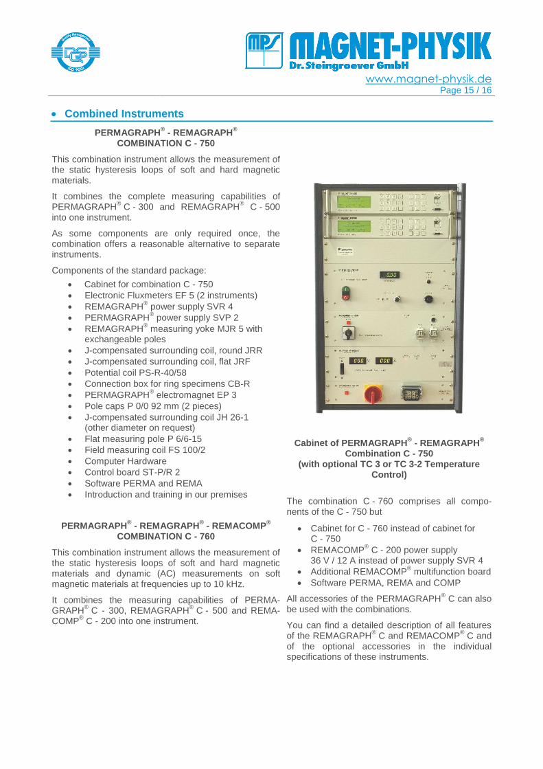
Segment Poles MC-BLW
For the measurement of flux curves of ferrite segment magnets according to the standard DIN 50472. The set of poles is constructed corresponding to the dimensions of the segment magnet.
A coil in one of the poles senses the total magnetic flux penetrating the magnet. The pole distance is fixed and the measurement is carried out with a well-defined air gap. A sheared hysteresis loop is obtained.
The poles are suitable for the use in the electromagnets EP 3 or EP 5. For the measure-ment you also need one field coil FS 100/2.
Segment Pole MC-BLW
www.magnet-physik.de Page 15 / 16
Combined Instruments
PERMAGRAPH® - REMAGRAPH
®
COMBINATION C - 750
This combination instrument allows the measurement of the static hysteresis loops of soft and hard magnetic materials.
It combines the complete measuring capabilities of PERMAGRAPH
® C - 300 and REMAGRAPH
® C - 500
into one instrument.
As some components are only required once, the combination offers a reasonable alternative to separate instruments.
Components of the standard package:
Cabinet for combination C - 750
Electronic Fluxmeters EF 5 (2 instruments)
REMAGRAPH® power supply SVR 4
PERMAGRAPH® power supply SVP 2
REMAGRAPH® measuring yoke MJR 5 with
exchangeable poles
J-compensated surrounding coil, round JRR
J-compensated surrounding coil, flat JRF
Potential coil PS-R-40/58
Connection box for ring specimens CB-R
PERMAGRAPH® electromagnet EP 3
Pole caps P 0/0 92 mm (2 pieces)
J-compensated surrounding coil JH 26-1 (other diameter on request)
Flat measuring pole P 6/6-15
Field measuring coil FS 100/2
Computer Hardware
Control board ST-P/R 2
Software PERMA and REMA
Introduction and training in our premises
PERMAGRAPH® - REMAGRAPH
® - REMACOMP
®
COMBINATION C - 760
This combination instrument allows the measurement of the static hysteresis loops of soft and hard magnetic materials and dynamic (AC) measurements on soft magnetic materials at frequencies up to 10 kHz.
It combines the measuring capabilities of PERMA-GRAPH
® C - 300, REMAGRAPH
® C - 500 and REMA-
COMP® C - 200 into one instrument.
Cabinet of PERMAGRAPH® - REMAGRAPH
®
Combination C - 750 (with optional TC 3 or TC 3-2 Temperature
Control)
The combination C - 760 comprises all compo-nents of the C - 750 but
Cabinet for C - 760 instead of cabinet for C - 750
REMACOMP® C - 200 power supply
36 V / 12 A instead of power supply SVR 4
Additional REMACOMP® multifunction board
Software PERMA, REMA and COMP
All accessories of the PERMAGRAPH® C can also
be used with the combinations.
You can find a detailed description of all features of the REMAGRAPH
® C and REMACOMP
® C and
of the optional accessories in the individual specifications of these instruments.
www.magnet-physik.de Page 16 / 16
MAGNET-PHYSIK Dr. Steingroever GmbH Emil-Hoffmann-Straße 3, 50996 Köln, Germany
Phone: +49 2236 3919-0 ▪ Fax: +49 2236 3919-19
[email protected] www.magnet-physik.de
MAGNET-PHYSICS Inc. 6330 East 75th Street, Suite 224, Indianapolis, IN 46250, USA
Phone: +1 317 577 8700 ▪ Fax: +1 317 578 2510
[email protected] www.magnet-physics.com
3115/18 PERMAGRAPH C © MAGNET-PHYSIK Dr. Steingroever GmbH, Köln 2018
Further Accessories
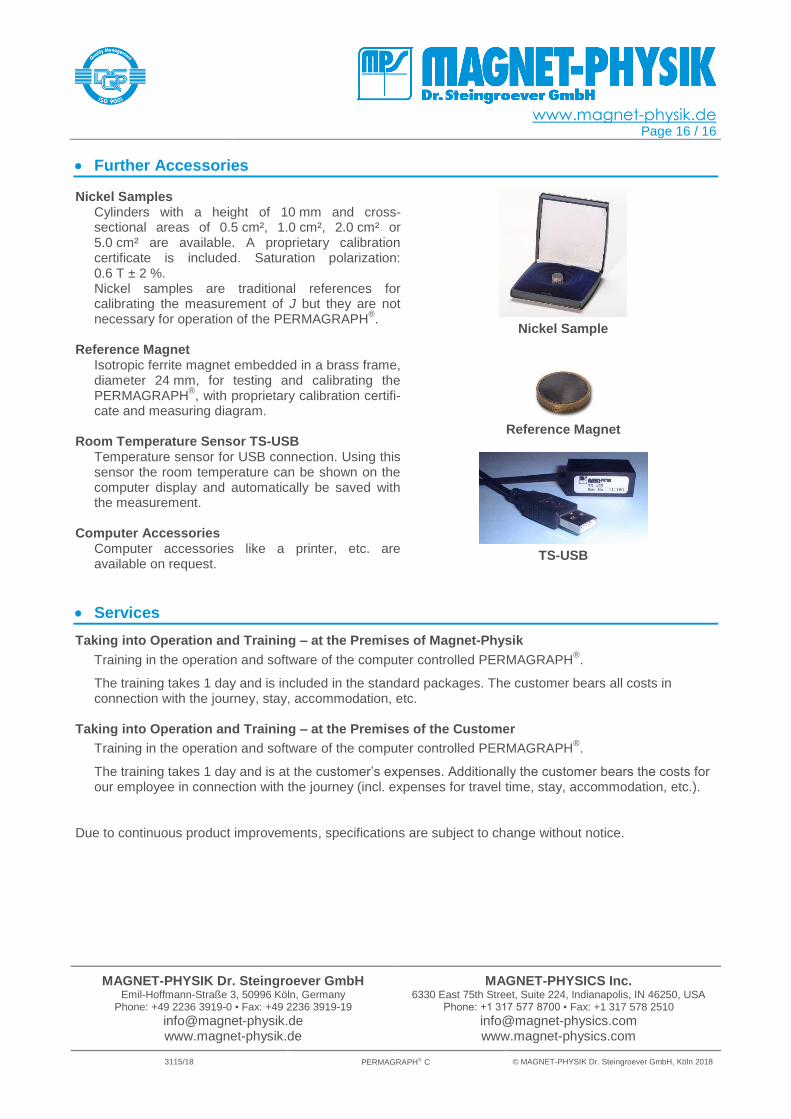
Nickel Samples Cylinders with a height of 10 mm and cross-sectional areas of 0.5 cm², 1.0 cm², 2.0 cm² or 5.0 cm² are available. A proprietary calibration certificate is included. Saturation polarization: 0.6 T ± 2 %. Nickel samples are traditional references for calibrating the measurement of J but they are not necessary for operation of the PERMAGRAPH
®.
Reference Magnet
Isotropic ferrite magnet embedded in a brass frame, diameter 24 mm, for testing and calibrating the PERMAGRAPH
®, with proprietary calibration certifi-
cate and measuring diagram.
Room Temperature Sensor TS-USB Temperature sensor for USB connection. Using this sensor the room temperature can be shown on the computer display and automatically be saved with the measurement.
Computer Accessories Computer accessories like a printer, etc. are available on request.
Nickel Sample
Reference Magnet
TS-USB
Services
Taking into Operation and Training – at the Premises of Magnet-Physik
Training in the operation and software of the computer controlled PERMAGRAPH®.
The training takes 1 day and is included in the standard packages. The customer bears all costs in connection with the journey, stay, accommodation, etc.
Taking into Operation and Training – at the Premises of the Customer
Training in the operation and software of the computer controlled PERMAGRAPH®.
The training takes 1 day and is at the customer’s expenses. Additionally the customer bears the costs for our employee in connection with the journey (incl. expenses for travel time, stay, accommodation, etc.).
Due to continuous product improvements, specifications are subject to change without notice.