performance of bubble deck slabumpir.ump.edu.my/id/eprint/26124/1/performance of bubble deck.pdf ·...
TRANSCRIPT
PERFORMANCE
OF
BUBBLE DECK SLAB
LIEW MUN KAI
B. ENG (HONS.) CIVIL ENGINEERING
UNIVERSITI MALAYSIA PAHANG
SUPERVISOR’S DECLARATION
I hereby declare that I have checked this thesis and in my opinion, this thesis is
adequate in terms of scope and quality for the award of the Bachelor Degree in Civil
Engineering.
_______________________________
(Supervisor’s Signature)
Full Name : Dr Nor Ashikin Muhamad Khairussaleh
Position : Senior Lecturer
Date : 11 JUNE 2018
STUDENT’S DECLARATION
I hereby declare that the work in this thesis is based on my original work except for
quotations and citations which have been duly acknowledged. I also declare that it has
not been previously or concurrently submitted for any other degree at Universiti
Malaysia Pahang or any other institutions.
_______________________________
(Student’s Signature)
Full Name : LIEW MUN KAI
ID Number : AA 14133
Date : 11 JUNE 2018
PERFORMANCE
OF
BUBBLE DECK SLAB
LIEW MUN KAI
Thesis submitted in fulfillment of the requirements
for the award of the
Bachelor Degree in Civil Engineering
Faculty of Civil Engineering and Earth Resources
UNIVERSITI MALAYSIA PAHANG
JUNE 2018
ii
ACKNOWLEDGEMENTS
First and foremost, I would like to show my gratitude and thank my supervisor, Dr. Nor
Ashikin Binti Muhamad Khairussaleh for her supervision, advice, guidance,
encouragement and support in completing my research. Her guidance helped me
throughout the research study and thesis writing. I have been amazingly fortunate to
have a supervisor who gave me the freedom to explore on my own, and at the same
time the guidance to recover when my steps faltered.
In addition, I would like to thank Mr. Muhammad Nurul Fakhri Bin Rusli from the
bottom of my heart for offering guidance, information and advice in helping me to
complete my Final Year Project. Furthermore, I wish to express sincere thanks to all the
technician assistants of Concrete Laboratory, Faculty of Civil Engineering and Earth
Resources, University Malaysia Pahang (UMP) for assisting me in conducting the
laboratory works.
I would like to give a special thanks to my beloved friend, Kam Seng Hai who is always
there providing me with help as an additional workforce during the execution of my
project works and sincerely offering me suggestions and ideas regarding my Final Year
Project. Moreover, I would like to take this opportunity to give my warmest thanks to
all of those who have helped me with my works and have collaborated the ideas to
complete my thesis.
Lastly, I owe my loving thanks especially to my beloved mother, father and siblings
who always give me their moral support, encouragement and pray for my success. Their
understanding and encouragement gave me the strength to concentrate on my studies
and complete my Final Year Project on time.
iii
ABSTRAK
Struktur slab dianggap sebagai salah satu struktur terbesar yang menggunakan sejumlah
besar konkrit dalam pembinaan bangunan. Konkrit adalah bahan tunggal yang paling
banyak digunakan di dunia. Malangnya, konkrit mempunyai masalah [6]. Bahan-bahan
konkrit yang dicipta akan mencemarkan alam sekitar. Pada tahun 1990-an, Jorgen
Bruenig telah mencipta slab berongga biaxial yang pertama yang dipanggil slab
gelembung dek. Sistem slab gelembung dek bertindak sebagai kaedah praktikal
membuang jumlah konkrit dari tengah-tengah slab lantai kerana tidak melaksanakan
sebarang tujuan struktur [1]. Oleh itu, ia mengurangkan berat mati struktur secara
dramatik kerana jumlah signifikan konkrit telah 'dipindahkan'. Kekosongan di tengah-
tengah slab rata dipenuhi dengan sfera plastik yang membuang slab berat diri. Secara
mengagumkan, penyingkiran berat badan slab kira-kira hasil sebanyak 35% dalam
mengurangkan sekatan beban mati yang tinggi dan span yang pendek [9]. Jumlah
kuantiti konkrit yang dikurangkan telah mengakibatkan penurunan pengeluaran karbon
dioksida secara tidak langsung dan dengan menggunakan plastik kitar semula sebagai
bahan pengganti alternatif untuk sistem konkrit gelembung dek boleh dianggap sebagai
kaedah pembinaan slab yang menyumbang kepada teknologi hijau. Prestasi papak
gelembung gelung ditentukan dengan perbandingan dibuat terhadap papak
konvensional yang berdasarkan kekuatan lenturan, jenis kegagalan dan corak retak dan
penyebaran. Spesimen yang digunakan ialah 1500mm dengan 1500mm untuk lebar dan
panjang dengan ketebalan 285mm. Sebanyak 25 gelembung plastik HDPE berongga
ketebalan 230mm telah digunakan untuk spesimen gelembung dek. Besi tetulang keluli
yang digunakan ialah tebal 6mm keluli hasil ringan. Tambahan pula, sebanyak 12 kiub
konkrit dimensi 150 kubik mm dengan gred konkrit 30 dibahagikan kepada 4 jenis
masa pengawetan konkrit dengan 3 setiap satu iaitu 3 hari, 7 hari, 14 hari dan 28 hari
sebelum ujian mampatan dilakukan. Selain itu, ujian tegangan telah dijalankan untuk
menghasilkan keluli yang tinggi bersaiz 8mm dan 10mm manakala keluli ringan adalah
6mm, 8mm dan 10mm. Ujian fleksural dilakukan pada kedua-dua slab gelembung dek
dan slab konvensional dengan menggunakan tiga ujian lenturan titik selepas
pengawetan kedua-dua slab dalam air selama 28 hari. Daripada keputusan yang
diperoleh, penurunan kekuatan ricih sebanyak 53% untuk slab gelembung dek
manakala 36% untuk slab pepejal konvensional dengan kekuatan ricih reka bentuk
136.64 kN. Kekuatan lenturan slab gelembung dek adalah 447.51 MPa yang lebih
rendah daripada slab konvensional, 608.09 MPa. Ia dapat disimpulkan bahawa slab
gelembung dek dengan berat badan yang lebih rendah dan dimensi yang sama
berbanding dengan papak pepejal konvensional mempunyai beban muktamad yang
lebih tinggi daripada papak pepejal konvensional. Selain itu, pada beban puncak,
retakan utama dan mikro retakan berlaku di tepi berhampiran pertengahan slab.
iv
ABSTRACT
Slab structure is considered as one of the largest structural members that consumes
large amount of concrete in a building construction. Concrete is the single most widely
used material in the world. Unfortunately, concrete has a problem [6]. Concrete created
substances that polluted the environment. In the 1990’s, Jorgen Bruenig had invented
the first biaxial voided slab called bubble deck slab. Bubble deck slab system acts as a
method of practically removing the concrete volume from the middle of a floor slab for
not performing any structural purpose [1]. Thereby it reduces the structural dead weight
dramatically as significant amount of concrete volume has been ‘evacuated’. The voids
in the middle of a flat slab are filled with plastic spheres that remove the self-weight of
slab. Impressively, the removal of self-weight of the slab approximately result by 35%
in removing the restriction of high dead loads and short spans [9]. The reduced amount
of concrete volume has led to the decreasing production of carbon dioxide indirectly
and by using recycled plastic as an alternative replacement material for concrete, bubble
deck slab system can be considered as a slab construction method that contributes to
green technology. The performance of bubble deck slab was determined with
comparisons being made against the conventional solid slab which was based on the
flexural strength, type of failures and the crack pattern and propagation. The specimens
used were 1500mm by 1500mm for width and length with a thickness of 285mm. A
total of 25 HDPE hollow plastic bubble balls of thickness 230mm were used for the
bubble deck slab specimen. The reinforcement steel bar meshes used were 6mm thick
of mild yield steel. Furthermore, a total of 12 concrete cubes of dimensions 150 cubic
mm with concrete grade 30 were divided into 4 kinds of concrete curing periods with 3
each which were 3 days, 7 days, 14 days and 28 days before compression test was
conducted. Apart from that, tensile test was carried out for high yield steel size 8mm
and 10mm while mild steel are 6mm, 8mm and 10mm. Flexural test was done on both
the bubble deck slab and conventional solid slab by the application of three point
flexural testing after both slabs were cured by water for a total of 28 days. From the
results obtained, the percentage drop of shear strength was 53% for bubble deck slab
whilst 36% for conventional solid slab with comparison with design shear strength of
136.64 kN. The modulus of rupture of bubble deck slab was 447.51 MPa which was
lower than conventional slab, 608.09 MPa. It can be concluded that bubble deck slab
with lower self-weight and same dimensions as compared to conventional solid slab has
a higher ultimate load than conventional solid slab. Moreover, at peak load,
microcracking occurred at the sides near the middle of the slab.
v
TABLE OF CONTENT
DECLARATION
TITLE PAGE
ACKNOWLEDGEMENTS ii
ABSTRAK iii
ABSTRACT iv
TABLE OF CONTENT v
LIST OF TABLES ix
LIST OF FIGURES x
LIST OF SYMBOLS xii
LIST OF ABBREVIATIONS xiii
CHAPTER 1 INTRODUCTION 1
1.1 History Background 1
1.2 Problem Statement 3
1.3 Objective 4
1.4 Scope of Study 5
1.5 Significance of Study 6
CHAPTER 2 LITERATURE REVIEW 8
2.1 Introduction 8
2.2 Materials 8
2.2.1 Concrete 8
2.2.2 Steel 8

vi
2.2.3 Plastic Hollow Spheres 9
2.3 High Density Polyethylene or HDPE 12
2.3.1 History of HDPE 12
2.3.2 Physical Chemistry and Mechanical Properties of HDPE 13
2.3.3 Advantages of HDPE 16
2.4 Basic Principle of Schematic Design 17
2.5 Fire Resistance 18
2.6 Types of Bubble Deck 19
2.6.1 Type A - Filigree Elements 19
2.6.2 Type B - Reinforcement Modules 19
2.6.3 Type C - Finished Planks 20
2.7 Advantages of Bubble Deck 20
2.7.1 Material and Weight Reduction 21
2.7.2 Construction and Time Saving 21
2.7.3 Cost Saving 21
2.7.4 Green Design 22
2.8 Structural Properties 22
2.8.1 Technical Certifications 23
2.8.2 Bending Stiffness and Deflection 24
2.8.3 Shear Strength 26
2.8.4 Punching Shear 28
2.9 Flexural Testing 33
2.10 Modelling of A Bubble Deck Slab Prototype 34
CHAPTER 3 METHODOLOGY 38
3.1 Introduction 38
vii
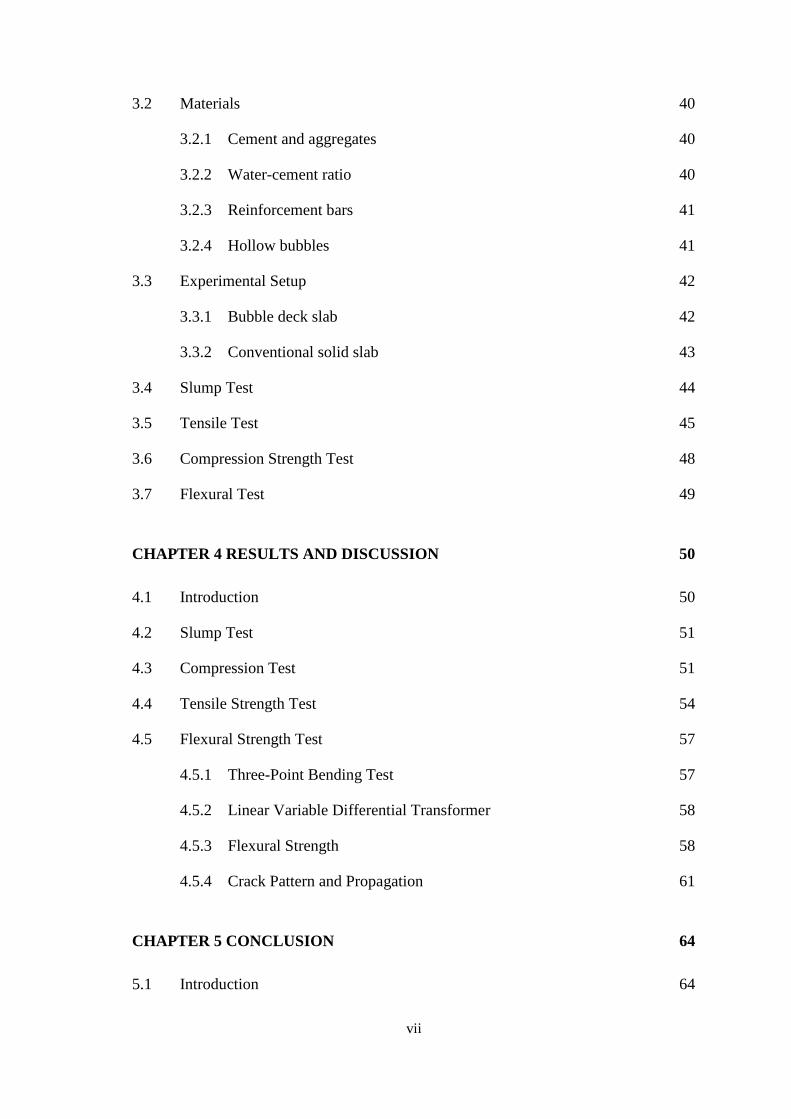
3.2 Materials 40
3.2.1 Cement and aggregates 40
3.2.2 Water-cement ratio 40
3.2.3 Reinforcement bars 41
3.2.4 Hollow bubbles 41
3.3 Experimental Setup 42
3.3.1 Bubble deck slab 42
3.3.2 Conventional solid slab 43
3.4 Slump Test 44
3.5 Tensile Test 45
3.6 Compression Strength Test 48
3.7 Flexural Test 49
CHAPTER 4 RESULTS AND DISCUSSION 50
4.1 Introduction 50
4.2 Slump Test 51
4.3 Compression Test 51
4.4 Tensile Strength Test 54
4.5 Flexural Strength Test 57
4.5.1 Three-Point Bending Test 57
4.5.2 Linear Variable Differential Transformer 58
4.5.3 Flexural Strength 58
4.5.4 Crack Pattern and Propagation 61
CHAPTER 5 CONCLUSION 64
5.1 Introduction 64

viii
5.2 Conclusion 64
5.3 Recommendation 66
REFERENCES 68
APPENDIX A SAMPLE APPENDIX 1 70
ix
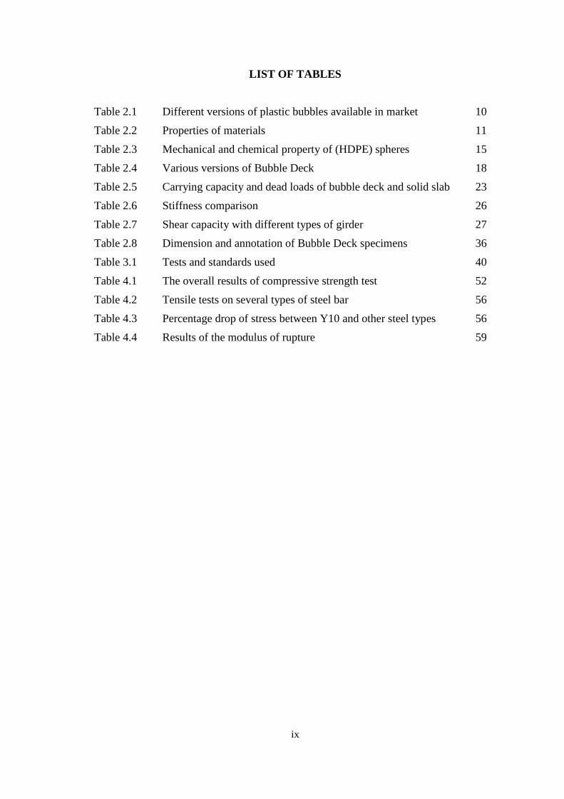
LIST OF TABLES
Table 2.1 Different versions of plastic bubbles available in market 10
Table 2.2 Properties of materials 11
Table 2.3 Mechanical and chemical property of (HDPE) spheres 15
Table 2.4 Various versions of Bubble Deck 18
Table 2.5 Carrying capacity and dead loads of bubble deck and solid slab 23
Table 2.6 Stiffness comparison 26
Table 2.7 Shear capacity with different types of girder 27
Table 2.8 Dimension and annotation of Bubble Deck specimens 36
Table 3.1 Tests and standards used 40
Table 4.1 The overall results of compressive strength test 52
Table 4.2 Tensile tests on several types of steel bar 56
Table 4.3 Percentage drop of stress between Y10 and other steel types 56
Table 4.4 Results of the modulus of rupture 59
x
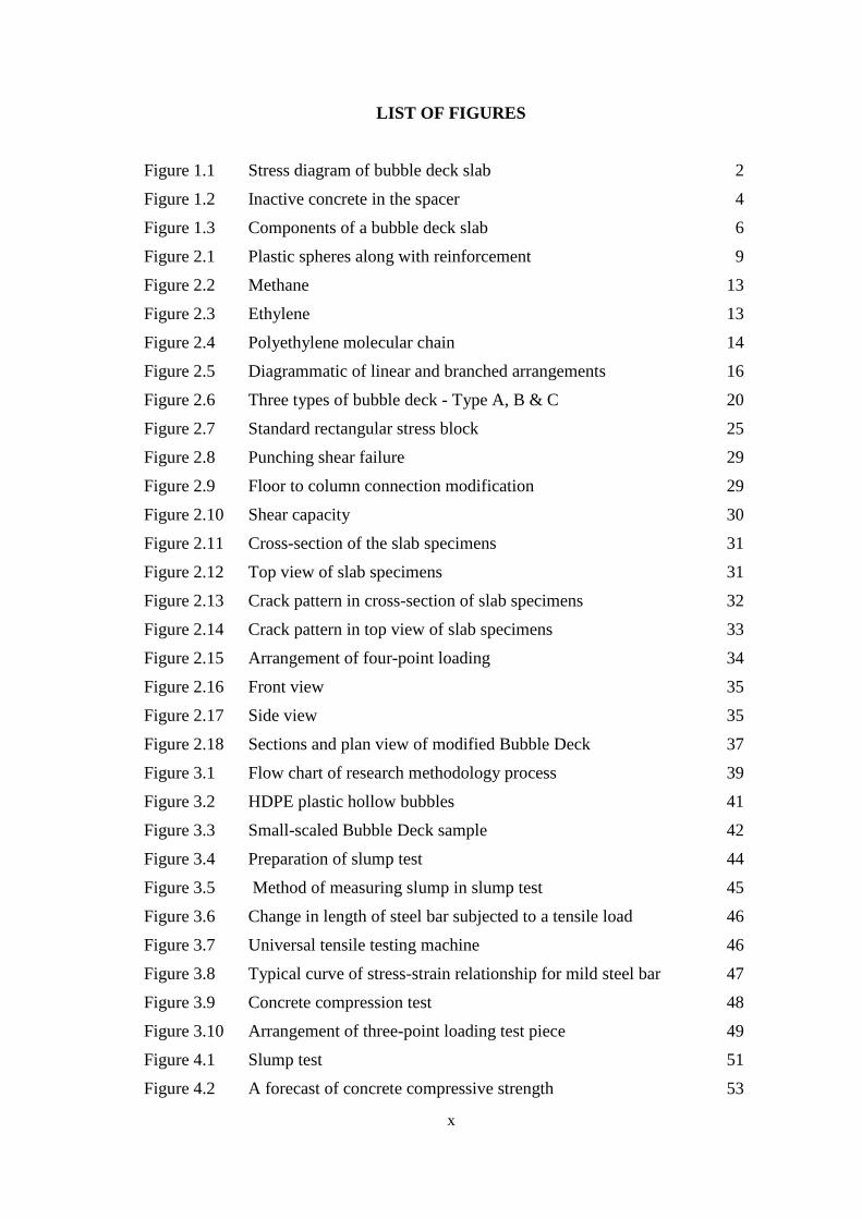
LIST OF FIGURES
Figure 1.1 Stress diagram of bubble deck slab 2
Figure 1.2 Inactive concrete in the spacer 4
Figure 1.3 Components of a bubble deck slab 6
Figure 2.1 Plastic spheres along with reinforcement 9
Figure 2.2 Methane 13
Figure 2.3 Ethylene 13
Figure 2.4 Polyethylene molecular chain 14
Figure 2.5 Diagrammatic of linear and branched arrangements 16
Figure 2.6 Three types of bubble deck - Type A, B & C 20
Figure 2.7 Standard rectangular stress block 25
Figure 2.8 Punching shear failure 29
Figure 2.9 Floor to column connection modification 29
Figure 2.10 Shear capacity 30
Figure 2.11 Cross-section of the slab specimens 31
Figure 2.12 Top view of slab specimens 31
Figure 2.13 Crack pattern in cross-section of slab specimens 32
Figure 2.14 Crack pattern in top view of slab specimens 33
Figure 2.15 Arrangement of four-point loading 34
Figure 2.16 Front view 35
Figure 2.17 Side view 35
Figure 2.18 Sections and plan view of modified Bubble Deck 37
Figure 3.1 Flow chart of research methodology process 39
Figure 3.2 HDPE plastic hollow bubbles 41
Figure 3.3 Small-scaled Bubble Deck sample 42
Figure 3.4 Preparation of slump test 44
Figure 3.5 Method of measuring slump in slump test 45
Figure 3.6 Change in length of steel bar subjected to a tensile load 46
Figure 3.7 Universal tensile testing machine 46
Figure 3.8 Typical curve of stress-strain relationship for mild steel bar 47
Figure 3.9 Concrete compression test 48
Figure 3.10 Arrangement of three-point loading test piece 49
Figure 4.1 Slump test 51
Figure 4.2 A forecast of concrete compressive strength 53
xi
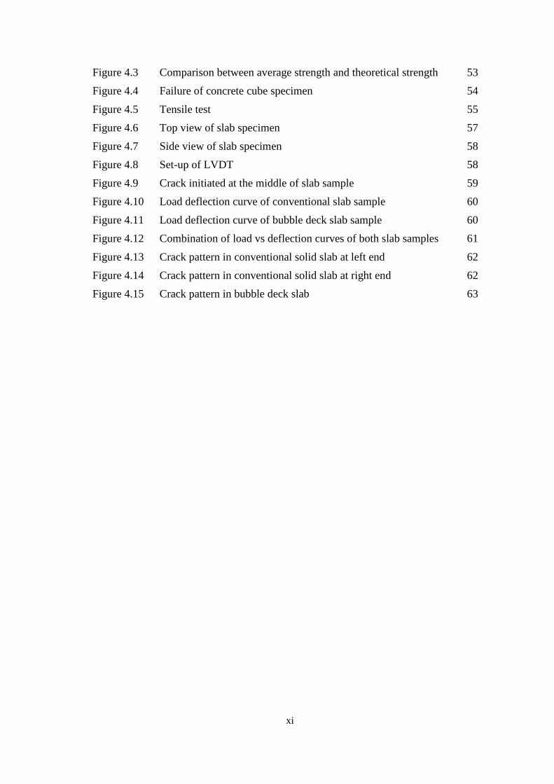
Figure 4.3 Comparison between average strength and theoretical strength 53
Figure 4.4 Failure of concrete cube specimen 54
Figure 4.5 Tensile test 55
Figure 4.6 Top view of slab specimen 57
Figure 4.7 Side view of slab specimen 58
Figure 4.8 Set-up of LVDT 58
Figure 4.9 Crack initiated at the middle of slab sample 59
Figure 4.10 Load deflection curve of conventional slab sample 60
Figure 4.11 Load deflection curve of bubble deck slab sample 60
Figure 4.12 Combination of load vs deflection curves of both slab samples 61
Figure 4.13 Crack pattern in conventional solid slab at left end 62
Figure 4.14 Crack pattern in conventional solid slab at right end 62
Figure 4.15 Crack pattern in bubble deck slab 63
xii
LIST OF SYMBOLS
ᵒc Degree Celsius
E Modulus of Elasticity
kN Kilo Newton
mm Millimetre
m Metre
% Percentage
kN/mm2 Kilo Newton per millimetre square
xiii
LIST OF ABBREVIATIONS
HDPE High Density Polyethylene
BD BubbleDeck
OPC Ordinary Portland Cement
UTM
LVDT
Eq.
et al
Universal Testing Machine
Linear Variable Differential Transformer
Equation
et alia
1
CHAPTER 1
INTRODUCTION
1.1 History Background
Slab structure is considered as one of the largest structural members that
consumes large amount of concrete in a building construction (Bhade & Barelikar,
2016). Since it requires a big amount of concrete volume, it has to be designed in
appropriate way. According to Bhade and Barelikar (2016), the deflection of the slab
structure tends to increase as the concentrated load acting on the slab is great which
leads to the expanding of slab thickness. The high thickness of slabs will create a
heavier slab due to the increasing of self-weight of and also the size of column and
foundations. In conclusion, the increase of size of structure members such as the beam
and column will generally increase the total amount of materials used and consequently
the cost increases as well.
In the mid-20th Century, the voided or hollow core floor system was created to
reduce the high weight-to-strength ratio of typical concrete systems. This concept
removes or replaces concrete from the centre of the slab, where it is less useful, with a
lighter material in order to decrease the dead weight of the concrete floor. However,
these hollow cavities significantly decrease the slabs resistance to shear and fire, thus
reducing its structural integrity (Lai, 2010). Thus, there is a numerous number of
researches continue to perform and conduct tests in order to overcome this problem
especially to the design engineers in order to reduce the weight of the slab structure
without affecting the structural integrity.
In the 1990’s, Jorgen Bruenig had invented the first biaxial voided slab called
bubble deck slab (Mirajkar et al, 2017). Bubble deck slab system acts as a method of
2
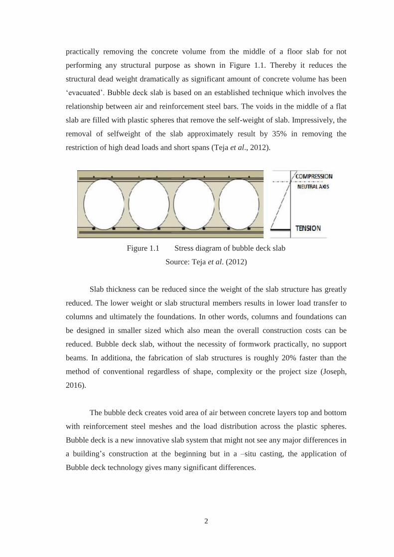
practically removing the concrete volume from the middle of a floor slab for not
performing any structural purpose as shown in Figure 1.1. Thereby it reduces the
structural dead weight dramatically as significant amount of concrete volume has been
‘evacuated’. Bubble deck slab is based on an established technique which involves the
relationship between air and reinforcement steel bars. The voids in the middle of a flat
slab are filled with plastic spheres that remove the self-weight of slab. Impressively, the
removal of selfweight of the slab approximately result by 35% in removing the
restriction of high dead loads and short spans (Teja et al., 2012).
Figure 1.1 Stress diagram of bubble deck slab
Source: Teja et al. (2012)
Slab thickness can be reduced since the weight of the slab structure has greatly
reduced. The lower weight or slab structural members results in lower load transfer to
columns and ultimately the foundations. In other words, columns and foundations can
be designed in smaller sized which also mean the overall construction costs can be
reduced. Bubble deck slab, without the necessity of formwork practically, no support
beams. In additiona, the fabrication of slab structures is roughly 20% faster than the
method of conventional regardless of shape, complexity or the project size (Joseph,
2016).
The bubble deck creates void area of air between concrete layers top and bottom
with reinforcement steel meshes and the load distribution across the plastic spheres.
Bubble deck is a new innovative slab system that might not see any major differences in
a building’s construction at the beginning but in a –situ casting, the application of
Bubble deck technology gives many significant differences.
3
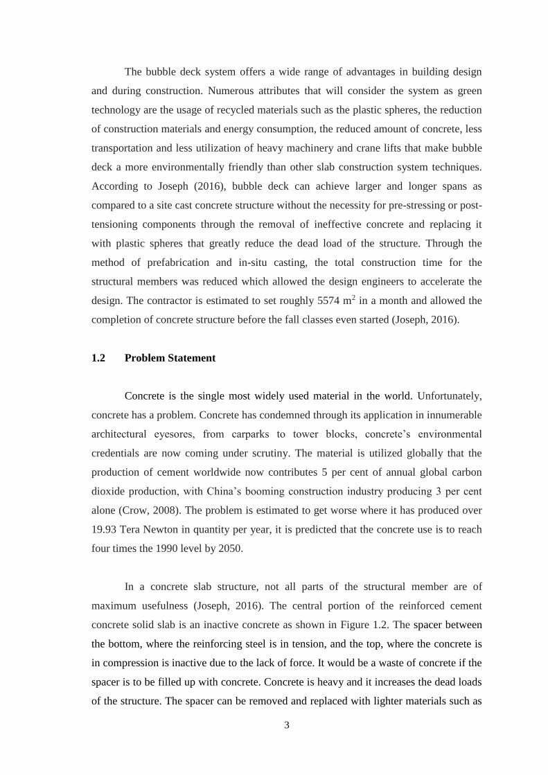
The bubble deck system offers a wide range of advantages in building design
and during construction. Numerous attributes that will consider the system as green
technology are the usage of recycled materials such as the plastic spheres, the reduction
of construction materials and energy consumption, the reduced amount of concrete, less
transportation and less utilization of heavy machinery and crane lifts that make bubble
deck a more environmentally friendly than other slab construction system techniques.
According to Joseph (2016), bubble deck can achieve larger and longer spans as
compared to a site cast concrete structure without the necessity for pre-stressing or post-
tensioning components through the removal of ineffective concrete and replacing it
with plastic spheres that greatly reduce the dead load of the structure. Through the
method of prefabrication and in-situ casting, the total construction time for the
structural members was reduced which allowed the design engineers to accelerate the
design. The contractor is estimated to set roughly 5574 m2 in a month and allowed the
completion of concrete structure before the fall classes even started (Joseph, 2016).
1.2 Problem Statement
Concrete is the single most widely used material in the world. Unfortunately,
concrete has a problem. Concrete has condemned through its application in innumerable
architectural eyesores, from carparks to tower blocks, concrete’s environmental
credentials are now coming under scrutiny. The material is utilized globally that the
production of cement worldwide now contributes 5 per cent of annual global carbon
dioxide production, with China’s booming construction industry producing 3 per cent
alone (Crow, 2008). The problem is estimated to get worse where it has produced over
19.93 Tera Newton in quantity per year, it is predicted that the concrete use is to reach
four times the 1990 level by 2050.
In a concrete slab structure, not all parts of the structural member are of
maximum usefulness (Joseph, 2016). The central portion of the reinforced cement
concrete solid slab is an inactive concrete as shown in Figure 1.2. The spacer between
the bottom, where the reinforcing steel is in tension, and the top, where the concrete is
in compression is inactive due to the lack of force. It would be a waste of concrete if the
spacer is to be filled up with concrete. Concrete is heavy and it increases the dead loads
of the structure. The spacer can be removed and replaced with lighter materials such as
68
REFERENCES
Bhade, B. G., & Barelikar, S. M. (2016). AN EXPERIMENTAL STUDY ON TWO WAY
BUBBLE DECK SLAB WITH SPHERICAL HOLLOW BALLS International Journal Of
Recent Bhagyas AN EXPERIMENTAL STUDY ON TWO WAY BUBBLE DECK
SLAB WITH SPHERICAL HOLLOW BALLS AN EXPERIMENTAL STUDY ON
TWO WAY BUBBLE DECK SLAB WITH SPHE. THE OFFICIAL PUBLICATION OF
INTERNATIONAL JOURNAL OF RECENT SCIENTIFIC RESEARCH (IJRSR) THE
OFFICIAL PUBLICATION OF INTERNATIONAL JOURNAL OF RECENT SCIENTIFIC
RESEARCH, 7(6). Retrieved from http://www.recentscientific.
BubbleDeck Voided Flat Slab Solutions. (2008). Retrieved from http://www.bubbledeck-
uk.com/pdf/2-BDTechManualv1a.pdf
Călin, S., Gînţu, R., & Dascălu, G. (n.d.). SUMARY OF TESTS AND STUDIES DONE
ABROAD ON THE BUBBLE DECK SYSTEM. Retrieved from
http://www.bipcons.ce.tuiasi.ro/Archive/157.pdf
Călin, S., Gînţu, R., & Dascălu, G. (2009). SUMARY OF TESTS AND STUDIES DONE
ABROAD ON THE BUBBLE DECK SYSTEM. Retrieved from
http://www.bipcons.ce.tuiasi.ro/Archive/157.pdf
Crow, J. M. (2008). The concrete conundrum. Chemistry World, (March), 62–66.
Gabriel, L. H. (n.d.). Chapter History and Physical Chemistry of HDPE History of HDPE and
HDPE Pipe. Retrieved from https://plasticpipe.org/pdf/chapter-
1_history_physical_chemistry_hdpe.pdf
Joseph, A. V. (2016). Structural Behaviour of Bubble Deck, (August).
https://doi.org/10.13140/RG.2.1.3287.6885
Kozłowski, M., Kadela, M., & Kukiełka, A. (2015). Fracture Energy of Foamed Concrete
Based on Three-Point Bending Test on Notched Beams. Procedia Engineering, 108, 349–
354. https://doi.org/10.1016/J.PROENG.2015.06.157
69
Lai, T. (2010). Structural Behavior of BubbleDeck * Slabs And Their Application to
Lightweight Bridge Decks, 42.
Mirajkar, S., Balapure, M., & Trupti Kshirsagar, A. (2017). STUDY OF BUBBLE DECK
SLAB. International Journal of Research In Science & Engineering, (7), 2394–8299.
Retrieved from www.ijrise.org%[email protected]
Ricker, M., Häusler, F., & Randl, N. (2017). Punching strength of flat plates reinforced with
UHPC and double- headed studs. https://doi.org/10.1016/j.engstruct.2017.01.018
Schnellenbach-Held, M., & Pfeffer, K. (2002). Punching behavior of biaxial hollow slabs.
Cement and Concrete Composites, 24(6), 551–556. https://doi.org/10.1016/S0958-
9465(01)00071-3
Shu, J., Belletti, B., Muttoni, A., Scolari, M., & Plos, M. (2017). Internal force distribution in
RC slabs subjected to punching shear. https://doi.org/10.1016/j.engstruct.2017.10.005
Teja, P. P., Kumar, P. V., Mounika, C. R., & Saha, P. (2012). Structural Behavior of Bubble
Deck Slab, (January 2012), 383–388.
Vakil, R. R., & Madhuri Nilesh, M. (2017). Comparative Study of Bubble Deck Slab and Solid
Deck Slab – A Review. Retrieved from
http://data.conferenceworld.in/IETEOCTOBER2017/28.pdf