performance of a poly(2,5-benzimidazole)-based polymer electrolyte membrane fuel cell
TRANSCRIPT
ww.sciencedirect.com
i n t e rn a t i o n a l j o u r n a l o f h y d r o g e n en e r g y 3 7 ( 2 0 1 2 ) 7 2 1 2e7 2 2 0
Available online at w
journal homepage: www.elsevier .com/locate/he
Performance of a poly(2,5-benzimidazole)-based polymerelectrolyte membrane fuel cell
Jose J. Linares, Cassandra Sanches, Valdecir A. Paganin, Ernesto R. Gonzalez*
Instituto de Quımica de Sao Carlos, University of Sao Paulo, Av. Trabalhador Sao-Carlense, 400 CP 780, CEP 13560-970 Sao Carlos, SP, Brazil
a r t i c l e i n f o
Article history:
Received 8 September 2011
Received in revised form
15 November 2011
Accepted 5 December 2011
Available online 30 December 2011
Keywords:
High temperature PEMFC
Cell performance
ABPBI
CO tolerance
Humidity
Temperature
* Corresponding author. Tel.: þ55 1633739899E-mail address: [email protected] (E.R.
0360-3199/$ e see front matter Copyright ªdoi:10.1016/j.ijhydene.2011.12.030
a b s t r a c t
The performance of an ABPBI-based High Temperature H2/O2 PEMFC system was studied
under different experimental conditions. Increasing the temperature from 130 to 170 �C
improved the cell performance, even though further increase was not beneficial for the
system. Humidification of the H2 stream ameliorated this behaviour, even though oper-
ating above 170 �C is not advisable in terms of cell performance. A significant electrolyte
dehydration seems to negatively affect the fuel cell performance, especially in the case of
the anode. In the presence of 2% vol. CO in the H2 stream, the temperature exerted
a positive effect on the cell performance, reducing the strong adsorption of this poison on
the platinum sites. Moreover, humidification of the H2 þ CO stream increased the
maximum power densities of the cell, further alleviating the CO poisoning effects. Actual
COeO2 fuel cell results confirmed the significant beneficial effect of the relative humidity
on the kinetics of the CO oxidation process.
Copyright ª 2011, Hydrogen Energy Publications, LLC. Published by Elsevier Ltd. All rights
reserved.
1. Introduction high temperatures [6,7]. Also, an enhancement of the oxygen
HighTemperature (120e200 �C) Polymer ElectrolyteMembrane
Fuel Cells (HT-PEMFC) are a promising alternative to low
temperature (up to 90 �C) Nafion� based PEMFC [1e4]. The idea
for developing this system arose from the limitations of the
traditional system, primarily from the point of view of the
tolerance to fuel impurities, such as the carbon monoxide
coming from a hydrocarbon reforming process [5]. In this
process, typical carbon monoxide contents of thousands of
ppm are obtained, making strictly mandatory the imple-
mentation of advanced CO cleaning processes (Partial Oxida-
tion, Water Gas Shift, Membrane Technology), which rises the
complexity and the cost of the system. One alternative to
overtake this limitation is to take advantage of the behaviour
of the CO adsorption process on platinum. This process
exhibits a negative value of the entropy, being disfavoured at
; fax: þ55 1633739903.Gonzalez).2011, Hydrogen Energy P
reduction reaction could be expected under those conditions.
Increasing the operational temperature requires materials
with a high thermal, mechanical and chemical stability, low
fuel and comburent permeability, and high proton conduc-
tivity [8]. Among the different existing options, poly-
benzimidazoles (PBIs) emerged as one of the most interesting
ones. Polybenzimidazoles are a family of highly aromatic
thermoplastic polymers with a high glass transition temper-
ature (Tg > 400), and a basic nature due to a pair of unpaired
electrons of two nitrogen atoms in the imidazole ring. Pure
PBIs are electronic and ionic insulators, but properly impreg-
nated with an acid, they become good proton conductors. One
of the most suitable acids is phosphoric acid. This acid is not
aggressive to the polymer structure, and has got a low vapour
pressure and a high chemical stability, allowing its use at high
temperatures, such as in the case of Phosphoric Acid Fuel
ublications, LLC. Published by Elsevier Ltd. All rights reserved.
i n t e r n a t i o n a l j o u r n a l o f h y d r o g e n en e r g y 3 7 ( 2 0 1 2 ) 7 2 1 2e7 2 2 0 7213
Cells (PAFC). Therefore, from the combination of PBIs with
H3PO4 arises a very interesting candidate for HT-PEMFC.
The most extensively used PBI is the Poly[2,2-(m-phenyl-
ene)-5,5-bibenzimidazole] (m-PBI). As Li et al. [1] recently
showed in a review, over the last 16 years, since the first
proposal of use of H3PO4-doped m-PBI for fuel cell application
by Prof. Savinell’s research group [9], there has been an expo-
nential growth in the interest for this material. Another poly-
mer of the family of the polybenzimidazole is the poly(2,5-
benzimidazole) (ABPBI). ABPBI can be easily synthesized from
a single monomer, 3,4-diaminobenzoic acid, obtaining more
easily high molecular weights [10]. This polymer was firstly
proposed for fuel cell applications by Litt et al. [11] in 1997, and
significantly developed by Prof. Gomez-Romero’s research
group [12]. However, less attention has been paid to this
system due to intrinsic handling difficulties, especially during
the preparation of the membrane (use of strong acids for the
casting procedure), aswell as, somehow, a lower performance.
Nonetheless, important straightforward steps have been
recently taken improving significantly the performance of this
system, as demonstrated by a series of recent papers [13e18].
In this context, this paper aims to study the behaviour of
a high temperature ABPBI-based PEMFC under different
experimental conditions. In the first part, it is analyzed the
influence of two typical operating variable, such as the
temperature and the humidification of the anode stream on
the cell performance, when operating the cell on neat
hydrogen. In the second part, the same study and protocol is
applied, but feeding the system with hydrogen contaminated
with carbon monoxide. Finally, pure CO was fed into the cell
operating on CO/O2 in order to assess the real capacity of the
system for oxidizing CO.
2. Materials and method
2.1. ABPBI polymer synthesis and membrane casting
ABPBI polymer was prepared by a polycondensation process
described elsewhere [19,20]. Briefly, it consisted of the auto-
polycondensation of 3,4-diaminobenzoic acid (97%, Aldrich)
in polyphosphoric acid (115% Aldrich) under inert atmosphere
at 150e180 �C for 5 h. Afterwards, the polymer solution was
poured into water, neutralized with NaOH, washed several
times with Milli-Q water, and dried at 80 �C overnight in
a vacuum oven. Once isolated the polymer powder, this was
dissolved in methanesulfonic acid (99.5%, Aldrich) at room
temperature, leaving the system until complete solution for
24 h. The polymer solution was then spread onto an optically
plane tempered glass plate, evaporating the solvent at 100 �C.Membranes were peeled off the support by immersion in
water, neutralized in a 10% wt. NH4OH solution, washed
several times in boiling Milli-Q water, and stored in 80%
H3PO4, at least for one week.
2.2. Preparation of the electrodes and the membrane-electrode-assembly
Electrodes were prepared as follows. A diffusion layer was
made with carbon powder (Vulcan XC-72R) and 15% w/w.
Teflon TE-3893 (Dupont) was applied homogeneously over
a carbon cloth (PWB-3, Stackpole) by vacuum filtration. On top
of this layer a catalyst ink was applied by brushing. The ink
was composed of a Pt/C catalyst (20% Pt on Vulcan XC-72R, E-
TEK Inc.), PBI (from Aldrich at 5% in N,N0-dimethylacetamide,
DMAc), and DMAc as solvent. The process took place on a hot
aluminium plate (60 �C). The platinum loading for both elec-
trodes was 0.5 mg/cm2, with a PBI loading normalized with
respect to the carbon catalyst loading (C/PBI ratio) of 20 [21].
Afterwards, the electrodes were cured in an oven at 190 �C for
2 h, and then impregnatedwith a 10%H3PO4 (loading of 20mg/
cm2), leaving them overnight in order to ensure the complete
soaking of the electrodes.
In order to prepare the membrane-electrode-assembly
(MEA), a piece of membrane was taken out from the H3PO4
doping bath, and placed between the electrodes (active area of
4.62 cm2). Hot pressing was carried out with the aid of a press,
applying 1 tonne and 150 �C for 15 min. MEAs prepared were
stored in sealed plastic bags for future use in the fuel cell.
2.3. Electrochemical measurements
The cell hardware consisted of two graphite monopolar
plates, into which a 4-channel serpentine geometry was
machined.Within the graphite plates, heating rodswere fitted
in order to heat the cell up. Temperature was controlled with
the aid of a temperature controller (Flyever). Temperatures
used in this study were 130e150e170e190 �C. During the
measurements, pure H2 or 2% vol. CO in H2 (White Martins)
were fed into the cell at a flow rate of 100 ml min�1. The
comburent, pure oxygen (White Martins) was introduced at
a flow rate of 75 ml min�1. In the case of the measurements in
which hydrogen was also introduced in the cathodic
compartment, the flow was readjusted to 100 ml min�1, and
humidified by bubbling inwater at room temperature. Relative
humidity of the fuel stream was controlled by applying the
fuel un-humidified or after bubbling it through a water
chamber at 25 �C or 60 �C. In order to prevent condensation of
the water vapour present in the hydrogen stream, the length
of the connecting pipe between the humidifier and the fuel
cell was shortened and electric heat traced. Assuming
complete saturation of the hydrogen stream at the corre-
sponding temperature, water vapour partial pressures were
approximately 2,500 and 20,000 Pa, respectively. Higher
temperatures of the water chamber did not lead to enhance-
ment in the cell performance, most likely due to an excessive
dilution of the fuel streams as Lobato et al. [22] demonstrated.
Previous to the polarization curves measurements at the
different temperatures and water vapour partial pressures,
the system was polarized at 0.6 V until stabilization of the
current (normally 2e3 h). Next, polarization curves were
carried out under potentiostatic conditions, waiting for
a stable value of the current. They were recorded with the aid
of a potentiostat/galvanostat AUTOLAB PGSTAT 302 (Ecoche-
mie) equipped with a current booster of 20 A from the lowest
to the highest temperature. Measurements were performed
from open circuit voltage (OCV) down to 100 mV.
In the case of the operation with H2 also in the cathode,
polarization curves were carried out under galvanostatic
conditions, from 0 to 90% of the maximum current density
0 250 500 750 1000 1250 1500 1750 0
100 200 300 400 500 600 700 800 900
Cell v
oltag
e / m
V
Current density / mA cm -2
0 50 100 150 200 250 300 350 400
Po
wer d
en
sity / m
W cm
-2
0 250 500 750 1000 1250 1500 1750 0
100 200 300 400 500 600 700 800 900
iR
c
orre
cte
d C
ell V
olta
ge
/ m
V
Current density / mA cm -2
0.0 10 100 1000 0
50
100
150
200
250
Sp
ec
ific
re
sista
nce
/ m
cm
2
Current density / mA cm -2
0 400 800 1200 1600 0
25
50
75
100
125
150
iR
co
rrected
an
od
e
po
te
ntia
l / m
V
Current density / mA cm -2
130ºC 150ºC 170ºC 190ºC
a
b
c
d
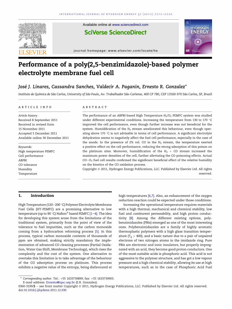
Fig. 1 e (a) Polarization curves (solid symbols) and power
density (hollow symbols), (b) iR-corrected polarization
curves, (c) Ohmic resistance vs. current density, and (d)
Polarization curves when operating the cell on H2/H2 at
different temperatures (-: 130 �C; C: 150 �C; :: 170 �C;
;: 190 �C). Cell operated on dry neat hydrogen at
atmospheric pressure. When operating on H2/H2 the
i n t e rn a t i o n a l j o u r n a l o f h y d r o g e n en e r g y 3 7 ( 2 0 1 2 ) 7 2 1 2e7 2 2 07214
achieved during the normal operation of the cell. Eventually,
in the case of the CO/O2 tests, the system was polarized
potentiostatically from OCV down to 0 V. The ohmic (iR)
contribution was assessed by AC impedance, taking the
uncompensated resistance obtained at high frequencies for
each point of the polarization curves.
3. Results and discussion
3.1. Performance on neat hydrogen fuel
3.1.1. Influence of the temperature on the cell performanceThe influence of the temperature on the cell behaviour of an
ABPBI-based PEMFC is displayed in Fig. 1. Firstly, Fig. 1(a)
shows the influence of the temperature on the actual cell
performance, and on the power density drawn from the cell.
In Fig. 1(b) the iR-corrected polarization curves are depicted.
Fig. 1(c) collects the corresponding values of the ohmic resis-
tance of the polarization curves of Fig. 1(a). Fig. 1(d) shows the
results corresponding to the H2/H2 operation of the cell. The
cell was operated on dry hydrogen and oxygen.
Influence of the temperature on the cell performance
shows an increment of the performance up to 150 �C, with no
further increases above this temperature, and even a decrease
when operating at 190 �C. The maximum power peak is ob-
tained at 150 �C with a value of 343 mW cm�2, decreasing at
190 �C to 257mWcm�2. This behaviour is not easily explained.
Indeed, in the literature, it is generally accepted that
increasing the temperature from 120 to 200 �C comes
accompanied of a monotonous enhancement of the cell
performance [22e25]. Lobato et al. [26] reported a similar
influence of the cell temperature on the analogous m-PBI-
based PEMFC system, showing that when the cell was left to
stabilize for 24 h at different temperatures, the subsequent
polarization curves showed an optimum performance at
150 �C. They explained their results mainly in terms of the
electrolyte dehydration, which increases the ohmic resis-
tance, and as a consequence of this, diminishes the electrode
performance, since the electrolyte within it is a key element
allowing the transportation of protons generated/consumed
in the electrochemical reactions. However, looking at Fig. 1(b)
and (c), it can be seen that actual larger ohmic resistance are
only observed when operating the cell at low current densi-
ties, region in which a detailed observation of the iR-corrected
polarization curves shows the expected positive intrinsic
effect of the temperature. Contrarily, at high current densities,
the ohmic resistance decreases with the temperature,
whereas the cell performance does not improve above 150 �C[if the ohmic resistance in the catalyst layer diminishes, an
enhancement in the electrode performance collected in
Fig. 1(b) may be expected]. The behaviour of the ohmic resis-
tance can be simply explained in terms of the larger hydration
of the electrolyte when operating the cell at high current
density, due to the large amount of water vapour produced in
the cathode. On the other hand, the explanation for the
cathode/pseudo-reference electrode was humidified at
room temperature.
0 400 800 1200 16000
100200300400500600700800900
050100150200250300350400
Ce
ll vo
ltag
e / m
V
Current density / mA cm-2
Po
wer d
en
sity
/ m
W c
m-2
0 400 800 1200 16000
100200300400500600700800900
Cell vo
lta
ge
/ m
V
Current density / mA cm-2
0.0 100 10000
50
100
150
200
250
Sp
ec
ific
resis
tan
ce
/ m
Ωc
m2
Current density / mA cm-2
0 400 800 1200 16000
20406080
100120140160
iR
c
orre
cte
d
an
od
e p
ote
ntial / m
V
Current density / mA cm-2
a
b
c
d
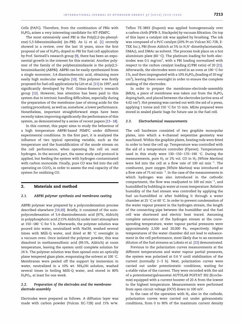
Fig. 2 e (a) Polarization curves (solid symbols) and power
density (hollow symbols), (b) iR-corrected polarization
curves, (c) Ohmic resistance vs. current density, and (d)
Polarization curves when operating the cell on H2/H2 at
different water vapour pressures (-: dry; C: 2,500 Pa; ::
20,000 Pa). Cell operated at 190 �C with neat hydrogen at
atmospheric pressure.
i n t e r n a t i o n a l j o u r n a l o f h y d r o g e n en e r g y 3 7 ( 2 0 1 2 ) 7 2 1 2e7 2 2 0 7215
behaviour of the electrode is more complex. The cell perfor-
mance comes from the summation of the anodic and cathodic
polarizations. It is generally, and most of the time correct to
assume, that most of it comes from the oxygen reduction
reaction [27]. Nonetheless, for this H3PO4-doped system, the
anode possesses a non-negligible contribution, as Seland et al.
[28] demonstrated. Indeed, having a look at the results when
operating the cell on H2/H2 mode [Fig. 1(d)], they are similar to
those of the overall polarization curves, with an enhancement
when the temperature was increased from 130 �C to 150 �C,and significantly worsening when operating at 190 �C.Therefore, a significant contribution of the performance
decays at high temperatures may come from the anode. The
electrolytewithin it is operating under strict dry conditions, so
that it can undergo a severe dehydration at the highest
temperature (despite the fact that in global terms the
ohmic resistance decreases with the temperature above
50 mA cm�2). This leads to a decrease in the performance of
the anode for the hydrogen oxidation reaction, and hence, in
the global cell performance.
3.1.2. Influence of the relative humidity on the cellperformanceIn view of the previous results, it seems interesting to study
the influence of introducing a pre-humidified hydrogen
stream on the anode. The presence of water vapour has been
reported to significantly enhance the ABPBI membrane
conductivity [19]. Therefore, it may be expected to observe
a beneficial effect of the relative humidity on the cell perfor-
mance. In this sense, Fig. 2 displays the cell performance at
190 �C after humidifying the fuel 25 �C and 60 �C. The
temperature of 190 �Cwas intentionally chosen because of the
significant drop in the cell performance ascribed to the
dehydration in the anode, as seen in Fig. 1(d). Fig. 2 displays
the cell performance at 190 �C as a function of fuel humidity in
a sequence similar to Fig. 1.
The pre-humidification of the hydrogen stream shows
a noticeable influence on the cell performancewhen operating
at 190 �C. The higher thewater vapour pressure, the higher the
maximum power of the cell, from 257 mW cm�2 for dry
hydrogen, to 358 mW cm�2 for a water vapour pressure of
20,000 Pa, which corresponds to an increase of 39%. Lobato
et al. [22] observed a similar behaviour, even though not as
notorious as in these results. As it canbe seen fromFig. 2(c), the
pre-humidification of the hydrogen stream causes a notable
decrease in the ohmic resistance of the system, attributed to
the increase in the electrolyte conductivity, althoughhumidity
is only applied in the anode. Large conductivity assists in
increasing the electrode performance with the relative
humidity. The importance of the relative humidity on the
performance of the anode is shown in Fig. 1(d). As can be
observed, the potential of the H2/H2 system diminishes the
higher the relative humidity in the anode streams, so the
hydrogen oxidation reaction is significantly enhanced when
operating with humidified fuel. Moreover, Liu et al. [29] re-
ported that the relative humidity increased the oxygen solu-
bility through the acid doped PBI. A similar behaviour should
not be disregarded with the hydrogen solubility in acid doped
ABPBI. Hydrogen solubility in doped polybenzimidazoles
system is significantly lowered compared to Nafion� [30].
i n t e rn a t i o n a l j o u r n a l o f h y d r o g e n en e r g y 3 7 ( 2 0 1 2 ) 7 2 1 2e7 2 2 07216
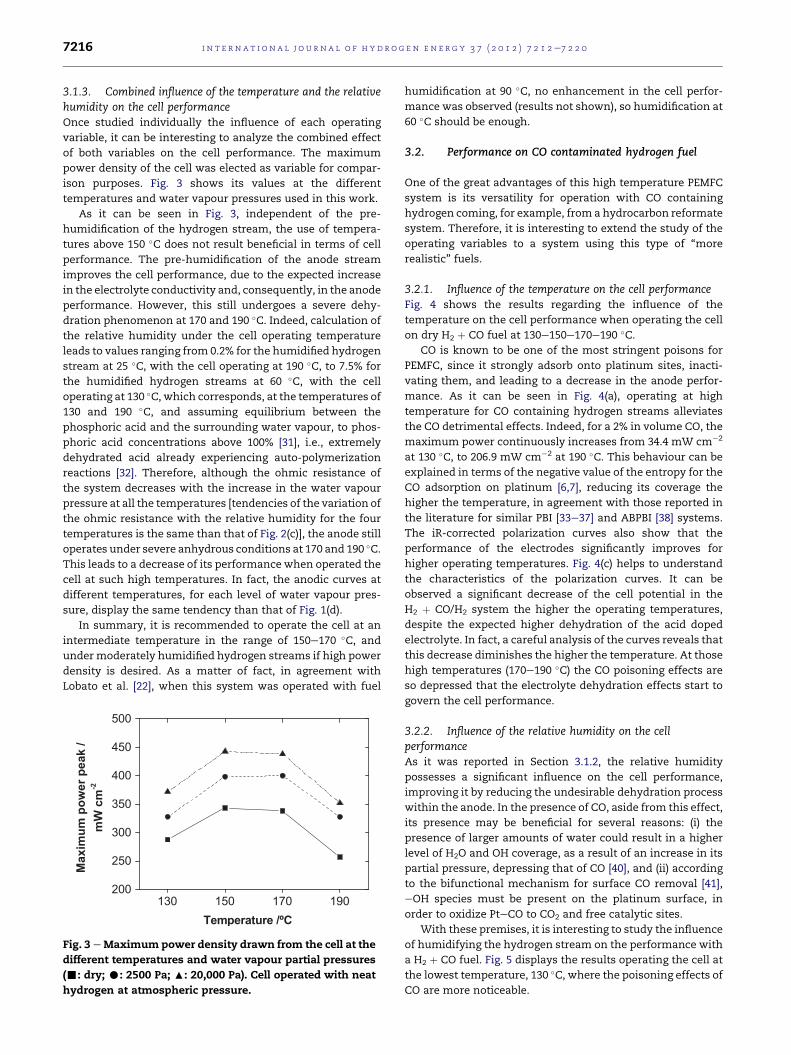
3.1.3. Combined influence of the temperature and the relativehumidity on the cell performanceOnce studied individually the influence of each operating
variable, it can be interesting to analyze the combined effect
of both variables on the cell performance. The maximum
power density of the cell was elected as variable for compar-
ison purposes. Fig. 3 shows its values at the different
temperatures and water vapour pressures used in this work.
As it can be seen in Fig. 3, independent of the pre-
humidification of the hydrogen stream, the use of tempera-
tures above 150 �C does not result beneficial in terms of cell
performance. The pre-humidification of the anode stream
improves the cell performance, due to the expected increase
in the electrolyte conductivity and, consequently, in the anode
performance. However, this still undergoes a severe dehy-
dration phenomenon at 170 and 190 �C. Indeed, calculation of
the relative humidity under the cell operating temperature
leads to values ranging from 0.2% for the humidified hydrogen
stream at 25 �C, with the cell operating at 190 �C, to 7.5% for
the humidified hydrogen streams at 60 �C, with the cell
operating at 130 �C, which corresponds, at the temperatures of
130 and 190 �C, and assuming equilibrium between the
phosphoric acid and the surrounding water vapour, to phos-
phoric acid concentrations above 100% [31], i.e., extremely
dehydrated acid already experiencing auto-polymerization
reactions [32]. Therefore, although the ohmic resistance of
the system decreases with the increase in the water vapour
pressure at all the temperatures [tendencies of the variation of
the ohmic resistance with the relative humidity for the four
temperatures is the same than that of Fig. 2(c)], the anode still
operates under severe anhydrous conditions at 170 and 190 �C.This leads to a decrease of its performance when operated the
cell at such high temperatures. In fact, the anodic curves at
different temperatures, for each level of water vapour pres-
sure, display the same tendency than that of Fig. 1(d).
In summary, it is recommended to operate the cell at an
intermediate temperature in the range of 150e170 �C, and
under moderately humidified hydrogen streams if high power
density is desired. As a matter of fact, in agreement with
Lobato et al. [22], when this system was operated with fuel
130 150 170 190200
250
300
350
400
450
500
Ma
xim
um
p
ow
er p
ea
k /
mW
c
m-2
Temperature /ºC
Fig. 3 eMaximum power density drawn from the cell at the
different temperatures and water vapour partial pressures
(-: dry; C: 2500 Pa; :: 20,000 Pa). Cell operated with neat
hydrogen at atmospheric pressure.
humidification at 90 �C, no enhancement in the cell perfor-
mance was observed (results not shown), so humidification at
60 �C should be enough.
3.2. Performance on CO contaminated hydrogen fuel
One of the great advantages of this high temperature PEMFC
system is its versatility for operation with CO containing
hydrogen coming, for example, from a hydrocarbon reformate
system. Therefore, it is interesting to extend the study of the
operating variables to a system using this type of “more
realistic” fuels.
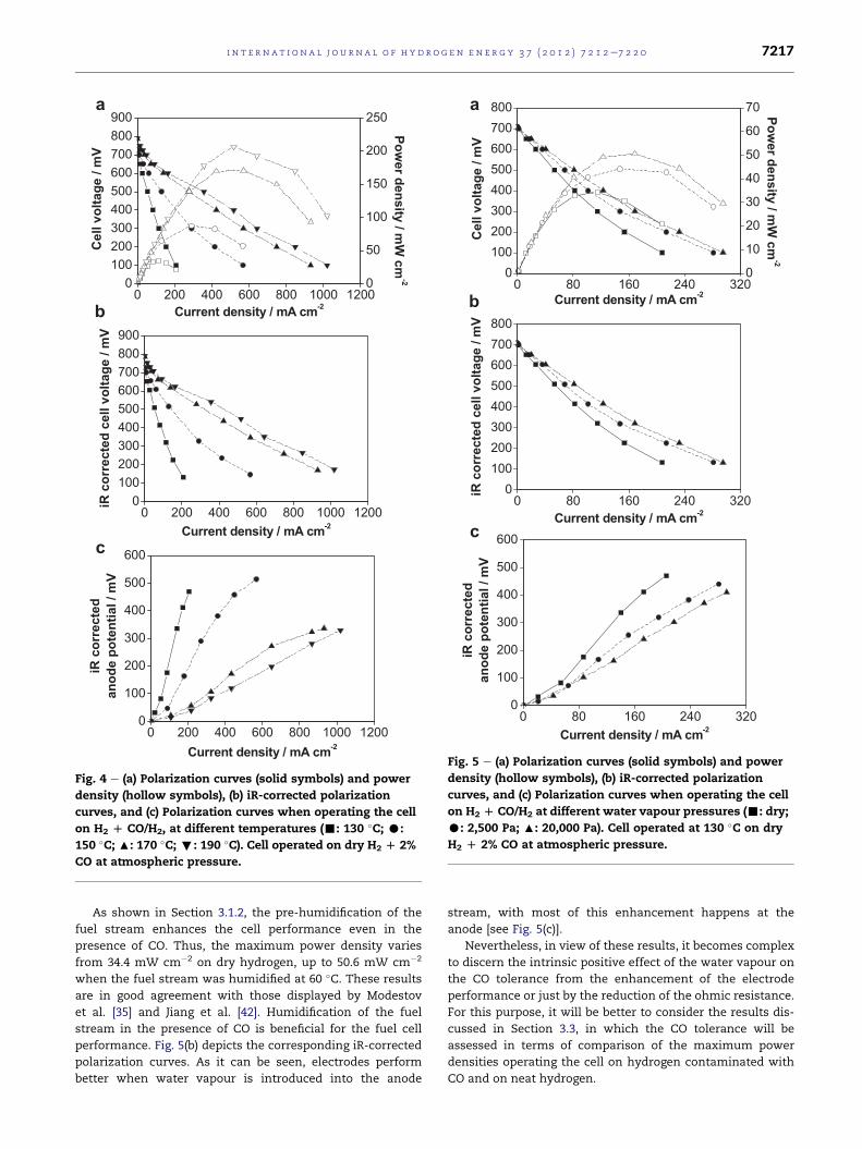
3.2.1. Influence of the temperature on the cell performanceFig. 4 shows the results regarding the influence of the
temperature on the cell performance when operating the cell
on dry H2 þ CO fuel at 130e150e170e190 �C.CO is known to be one of the most stringent poisons for
PEMFC, since it strongly adsorb onto platinum sites, inacti-
vating them, and leading to a decrease in the anode perfor-
mance. As it can be seen in Fig. 4(a), operating at high
temperature for CO containing hydrogen streams alleviates
the CO detrimental effects. Indeed, for a 2% in volume CO, the
maximum power continuously increases from 34.4 mW cm�2
at 130 �C, to 206.9 mW cm�2 at 190 �C. This behaviour can be
explained in terms of the negative value of the entropy for the
CO adsorption on platinum [6,7], reducing its coverage the
higher the temperature, in agreement with those reported in
the literature for similar PBI [33e37] and ABPBI [38] systems.
The iR-corrected polarization curves also show that the
performance of the electrodes significantly improves for
higher operating temperatures. Fig. 4(c) helps to understand
the characteristics of the polarization curves. It can be
observed a significant decrease of the cell potential in the
H2 þ CO/H2 system the higher the operating temperatures,
despite the expected higher dehydration of the acid doped
electrolyte. In fact, a careful analysis of the curves reveals that
this decrease diminishes the higher the temperature. At those
high temperatures (170e190 �C) the CO poisoning effects are
so depressed that the electrolyte dehydration effects start to
govern the cell performance.
3.2.2. Influence of the relative humidity on the cellperformanceAs it was reported in Section 3.1.2, the relative humidity
possesses a significant influence on the cell performance,
improving it by reducing the undesirable dehydration process
within the anode. In the presence of CO, aside from this effect,
its presence may be beneficial for several reasons: (i) the
presence of larger amounts of water could result in a higher
level of H2O and OH coverage, as a result of an increase in its
partial pressure, depressing that of CO [40], and (ii) according
to the bifunctional mechanism for surface CO removal [41],
eOH species must be present on the platinum surface, in
order to oxidize PteCO to CO2 and free catalytic sites.
With these premises, it is interesting to study the influence
of humidifying the hydrogen stream on the performance with
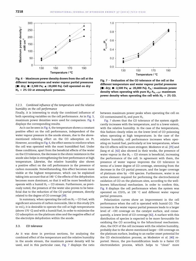
a H2 þ CO fuel. Fig. 5 displays the results operating the cell at
the lowest temperature, 130 �C, where the poisoning effects of
CO are more noticeable.
0 200 400 600 800 1000 12000
100200300400500600700800900
Ce
ll v
olta
ge
/ m
V
Current density / mA cm-2
0
50
100
150
200
250
Po
we
r d
en
sity
/ m
W c
m-2
0 200 400 600 800 1000 12000
100200300400500600700800900
iR
c
orre
cted
ce
ll v
oltag
e / m
V
Current density / mA cm-2
0 200 400 600 800 1000 12000
100
200
300
400
500
600
iR
co
rrected
an
od
e p
ote
ntia
l / m
V
Current density / mA cm-2
a
b
c
Fig. 4 e (a) Polarization curves (solid symbols) and power
density (hollow symbols), (b) iR-corrected polarization
curves, and (c) Polarization curves when operating the cell
on H2 D CO/H2, at different temperatures (-: 130 �C; C:
150 �C; :: 170 �C; ;: 190 �C). Cell operated on dry H2 D 2%
CO at atmospheric pressure.
0 80 160 240 3200
100200300400500600700800
Cell vo
ltag
e / m
V
Current density / mA cm-2
0
10
20
30
40
50
60
70P
ow
er d
en
sity / m
W cm
-2
0 80 160 240 3200
100200300400500600700800
iR
c
orre
cte
d c
ell v
olta
ge
/ m
V
Current density / mA cm-2
0 80 160 240 3200
100
200
300
400
500
600
iR
c
orre
cte
d
an
od
e p
ote
ntia
l / m
V
Current density / mA cm-2
a
b
c
Fig. 5 e (a) Polarization curves (solid symbols) and power
density (hollow symbols), (b) iR-corrected polarization
curves, and (c) Polarization curves when operating the cell
on H2 D CO/H2 at different water vapour pressures (-: dry;
C: 2,500 Pa; :: 20,000 Pa). Cell operated at 130 �C on dry
H2 D 2% CO at atmospheric pressure.
i n t e r n a t i o n a l j o u r n a l o f h y d r o g e n en e r g y 3 7 ( 2 0 1 2 ) 7 2 1 2e7 2 2 0 7217
As shown in Section 3.1.2, the pre-humidification of the
fuel stream enhances the cell performance even in the
presence of CO. Thus, the maximum power density varies
from 34.4 mW cm�2 on dry hydrogen, up to 50.6 mW cm�2
when the fuel stream was humidified at 60 �C. These results
are in good agreement with those displayed by Modestov
et al. [35] and Jiang et al. [42]. Humidification of the fuel
stream in the presence of CO is beneficial for the fuel cell
performance. Fig. 5(b) depicts the corresponding iR-corrected
polarization curves. As it can be seen, electrodes perform
better when water vapour is introduced into the anode
stream, with most of this enhancement happens at the
anode [see Fig. 5(c)].
Nevertheless, in view of these results, it becomes complex
to discern the intrinsic positive effect of the water vapour on
the CO tolerance from the enhancement of the electrode
performance or just by the reduction of the ohmic resistance.
For this purpose, it will be better to consider the results dis-
cussed in Section 3.3, in which the CO tolerance will be
assessed in terms of comparison of the maximum power
densities operating the cell on hydrogen contaminated with
CO and on neat hydrogen.
130 150 170 1900
50
100
150
200
250
300M
ax
im
um
p
ow
er d
en
sity
/
mW
c
m-2
Temperature / ºC
Fig. 6 eMaximum power density drawn from the cell at the
different temperatures and water vapour partial pressures
(-: dry; C: 2,500 Pa; :: 20,000 Pa). Cell operated on dry
H2 D 2% CO at atmospheric pressure.
130 150 170 1900.0
0.2
0.4
0.6
0.8
1.0
PH
+C
O/P
H
Temperature / °C
Fig. 7 e Evaluation of the CO tolerance of the cell at the
different temperature and water vapour partial pressures
(-: dry; C: 2,500 Pa; :: 20,000 Pa). PH2 : maximum power
density when operating with pure H2; PH2DCO: maximum
power density when operating the cell with H2 D 2% CO.
i n t e rn a t i o n a l j o u r n a l o f h y d r o g e n en e r g y 3 7 ( 2 0 1 2 ) 7 2 1 2e7 2 2 07218
3.2.3. Combined influence of the temperature and the relativehumidity on the cell performanceFinally, it is interesting to study the combined influence of
both operating variables on the cell performance. As in Fig. 3,
maximum power densities were used for comparison. Fig. 6
displays the corresponding results.
As it can be seen in Fig. 6, the temperature shows a constant
positive effect on the cell performance, independent of the
water vapour pressure in the anode stream, due to the above-
mentioned relieving effect on the CO adsorption on Pt.
However, according to Fig. 6, the effect seems to reinforcewhen
the cell was operated with the most humidified fuel. Under
these conditions, apart from the beneficial effects of the water
on theCO tolerance, the decrease in the ohmic resistance in the
anode also helps in strengthening the best performance at high
temperature. Likewise, the relative humidity also shows
a positive effect on the cell performance in the presence of
carbon monoxide. Notwithstanding, this effect becomes more
visible at the highest temperature, which can be explained
taking into account that at 190 �C the effects of the dehydration
becomes more dominant, so that it will be more beneficial to
operate with a humid H2 þ CO stream. Furthermore, as previ-
ously noted, the presence of the water also proves to be bene-
ficial due to the reduction of the CO partial pressure, directly
related to the degree of CO coverage [39].
In summary, when operating the cell on H2 þ CO fuel, with
significant amounts of carbonmonoxide, like in this study (2%
in vol.), it is desirable to operate the cell at high temperatures
(above 170 �C) and with a humid fuel, in order to minimize the
CO adsorption on the platinum sites and the negative effect of
the electrolyte dehydration within the anode.
3.3. CO tolerance
As it was done in previous sections, for analyzing the
combined effect of the temperature and the relative humidity
in the anode stream, the maximum power density will be
used, and in this particular case, Fig. 7 displays the ratio
between maximum power peaks when operating the cell on
CO contaminated H2 and pure H2.
Fig. 7 shows that the CO tolerance of the system signifi-
cantly increases with the temperature, and to a lower extent,
with the relative humidity. In the case of the temperatures,
this fashion clearly relies on the lower level of CO poisoning
when operating at high temperatures. In the case of the
relative humidity, cell performance increases when oper-
ating on humid fuel, particularly at low temperatures, where
the CO effects will be more stringent. Modestov et al. [35] and
Jiang et al. [42] also showed in their works, the presence of
water vapour in the H2 þ CO stream is beneficial, increasing
the performance of the cell. In agreement with them, the
presence of water vapour improves the CO tolerance in
terms of a lower degree of CO coverage, stemming from the
decrease in the CO partial pressure, and the larger coverage
of platinum sites by eOH species. Furthermore, water is an
active element required for performing the electrochemical
oxidation of CO on the platinum sites, according to the well-
known bifunctional mechanism. In order to confirm this,
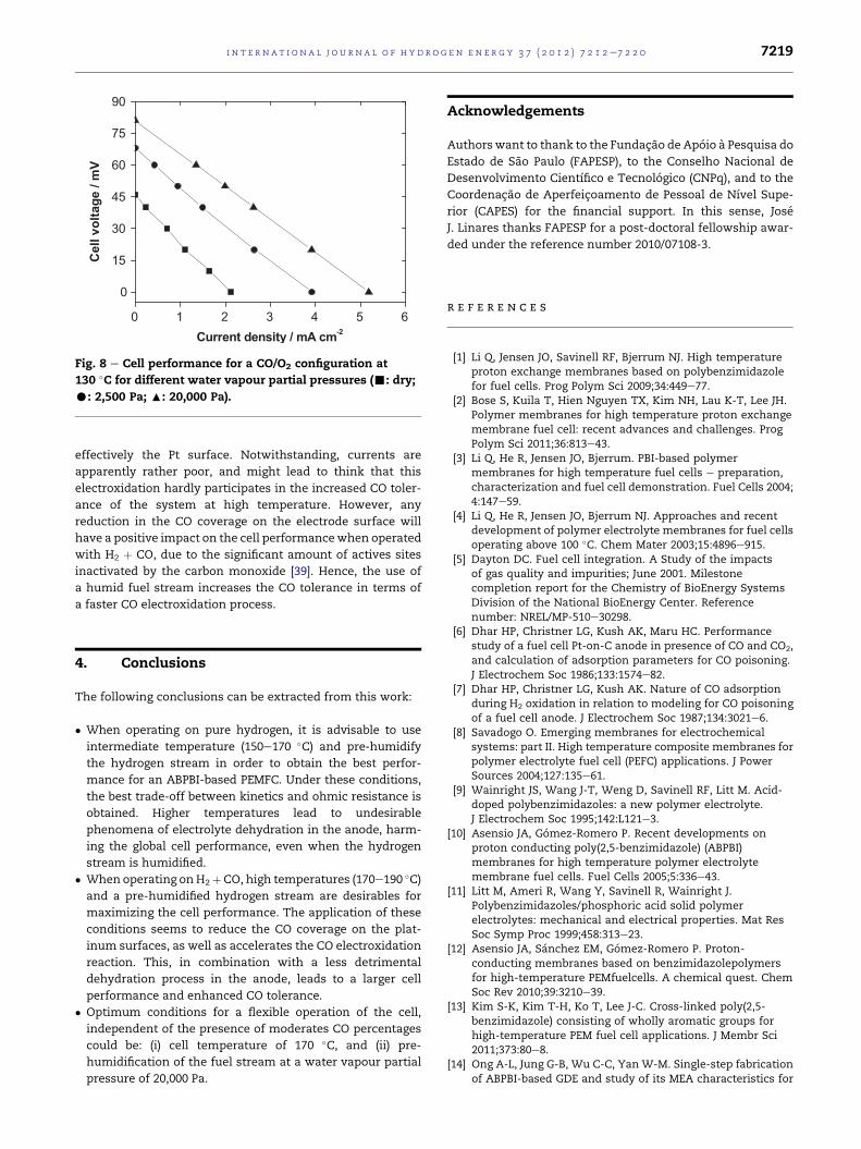
Fig. 8 displays the cell performance when the system was
operated on CO/O2 at 130 �C and different water vapour
partial pressures.
Polarization curves show an improvement in the cell
performance when the cell is operated with humid CO. The
increase in the water vapour partial pressure leads to a larger
level of eOH coverage on the catalyst surface, and conse-
quently, a lower level of CO coverage [42]. A surface with this
distribution of species is expected to be more favourable for
oxidizing the CO according to the bifunctional mechanism.
Also, the OCV of the cell increases with the relative humidity,
probably due to the above-mentioned larger eOH coverage on
the platinum surface, leading to an earlier onset potential for
the CO electroxidation process, as Modestov et al. [40] re-
ported. Hence, the pre-humidification leads to a faster CO
electroxidation process, which helps to “clean” more
0 1 2 3 4 5 6
0
15
30
45
60
75
90C
ell v
oltag
e / m
V
Current density / mA cm-2
Fig. 8 e Cell performance for a CO/O2 configuration at
130 �C for different water vapour partial pressures (-: dry;
C: 2,500 Pa; :: 20,000 Pa).
i n t e r n a t i o n a l j o u r n a l o f h y d r o g e n en e r g y 3 7 ( 2 0 1 2 ) 7 2 1 2e7 2 2 0 7219
effectively the Pt surface. Notwithstanding, currents are
apparently rather poor, and might lead to think that this
electroxidation hardly participates in the increased CO toler-
ance of the system at high temperature. However, any
reduction in the CO coverage on the electrode surface will
have a positive impact on the cell performancewhen operated
with H2 þ CO, due to the significant amount of actives sites
inactivated by the carbon monoxide [39]. Hence, the use of
a humid fuel stream increases the CO tolerance in terms of
a faster CO electroxidation process.
4. Conclusions
The following conclusions can be extracted from this work:
� When operating on pure hydrogen, it is advisable to use
intermediate temperature (150e170 �C) and pre-humidify
the hydrogen stream in order to obtain the best perfor-
mance for an ABPBI-based PEMFC. Under these conditions,
the best trade-off between kinetics and ohmic resistance is
obtained. Higher temperatures lead to undesirable
phenomena of electrolyte dehydration in the anode, harm-
ing the global cell performance, even when the hydrogen
stream is humidified.
� When operating onH2þCO, high temperatures (170e190 �C)and a pre-humidified hydrogen stream are desirables for
maximizing the cell performance. The application of these
conditions seems to reduce the CO coverage on the plat-
inum surfaces, as well as accelerates the CO electroxidation
reaction. This, in combination with a less detrimental
dehydration process in the anode, leads to a larger cell
performance and enhanced CO tolerance.
� Optimum conditions for a flexible operation of the cell,
independent of the presence of moderates CO percentages
could be: (i) cell temperature of 170 �C, and (ii) pre-
humidification of the fuel stream at a water vapour partial
pressure of 20,000 Pa.
Acknowledgements
Authorswant to thank to the Fundacao de Apoio a Pesquisa do
Estado de Sao Paulo (FAPESP), to the Conselho Nacional de
Desenvolvimento Cientıfico e Tecnologico (CNPq), and to the
Coordenacao de Aperfeicoamento de Pessoal de Nıvel Supe-
rior (CAPES) for the financial support. In this sense, Jose
J. Linares thanks FAPESP for a post-doctoral fellowship awar-
ded under the reference number 2010/07108-3.
r e f e r e n c e s
[1] Li Q, Jensen JO, Savinell RF, Bjerrum NJ. High temperatureproton exchange membranes based on polybenzimidazolefor fuel cells. Prog Polym Sci 2009;34:449e77.
[2] Bose S, Kuila T, Hien Nguyen TX, Kim NH, Lau K-T, Lee JH.Polymer membranes for high temperature proton exchangemembrane fuel cell: recent advances and challenges. ProgPolym Sci 2011;36:813e43.
[3] Li Q, He R, Jensen JO, Bjerrum. PBI-based polymermembranes for high temperature fuel cells e preparation,characterization and fuel cell demonstration. Fuel Cells 2004;4:147e59.
[4] Li Q, He R, Jensen JO, Bjerrum NJ. Approaches and recentdevelopment of polymer electrolyte membranes for fuel cellsoperating above 100 �C. Chem Mater 2003;15:4896e915.
[5] Dayton DC. Fuel cell integration. A Study of the impactsof gas quality and impurities; June 2001. Milestonecompletion report for the Chemistry of BioEnergy SystemsDivision of the National BioEnergy Center. Referencenumber: NREL/MP-510e30298.
[6] Dhar HP, Christner LG, Kush AK, Maru HC. Performancestudy of a fuel cell Pt-on-C anode in presence of CO and CO2,and calculation of adsorption parameters for CO poisoning.J Electrochem Soc 1986;133:1574e82.
[7] Dhar HP, Christner LG, Kush AK. Nature of CO adsorptionduring H2 oxidation in relation to modeling for CO poisoningof a fuel cell anode. J Electrochem Soc 1987;134:3021e6.
[8] Savadogo O. Emerging membranes for electrochemicalsystems: part II. High temperature composite membranes forpolymer electrolyte fuel cell (PEFC) applications. J PowerSources 2004;127:135e61.
[9] Wainright JS, Wang J-T, Weng D, Savinell RF, Litt M. Acid-doped polybenzimidazoles: a new polymer electrolyte.J Electrochem Soc 1995;142:L121e3.
[10] Asensio JA, Gomez-Romero P. Recent developments onproton conducting poly(2,5-benzimidazole) (ABPBI)membranes for high temperature polymer electrolytemembrane fuel cells. Fuel Cells 2005;5:336e43.
[11] Litt M, Ameri R, Wang Y, Savinell R, Wainright J.Polybenzimidazoles/phosphoric acid solid polymerelectrolytes: mechanical and electrical properties. Mat ResSoc Symp Proc 1999;458:313e23.
[12] Asensio JA, Sanchez EM, Gomez-Romero P. Proton-conducting membranes based on benzimidazolepolymersfor high-temperature PEMfuelcells. A chemical quest. ChemSoc Rev 2010;39:3210e39.
[13] Kim S-K, Kim T-H, Ko T, Lee J-C. Cross-linked poly(2,5-benzimidazole) consisting of wholly aromatic groups forhigh-temperature PEM fuel cell applications. J Membr Sci2011;373:80e8.
[14] Ong A-L, Jung G-B, Wu C-C, Yan W-M. Single-step fabricationof ABPBI-based GDE and study of its MEA characteristics for

i n t e rn a t i o n a l j o u r n a l o f h y d r o g e n en e r g y 3 7 ( 2 0 1 2 ) 7 2 1 2e7 2 2 07220
high-temperature PEM fuel cells. Int J Hydrogen Energ 2010;35:7866e73.
[15] Wippermann K, Wannek C, Oetjen H-F, Mergel J, Lehnert W.Cell resistances of poly(2,5-benzimidazole)-based hightemperature polymer membrane fuel cell membraneelectrode assemblies: time dependence and influence ofoperating parameters. J Power Sources 2010;195:2806e9.
[16] Zheng H, Petrik L, Mathe M. Preparation and characterisationof porous poly(2,5benzimidazole) (ABPBI) membranes usingsurfactants as templates for polymer electrolyte membranefuel cells. Int J Hydrogen Energy 2010;35:3745e50.
[17] Wannek C, Lehnert W, Mergel J. Membrane electrodeassemblies for high-temperature polymer electrolyte fuelcells based on poly(2,5-benzimidazole) membranes withphosphoric acid impregnation via the catalyst layers. J PowerSources 2009;192:258e66.
[18] Wannek C, Kohnen B, Oetjen H-F, Lippert H, Mergel J.Durability of ABPBI-based MEAs for high temperaturePEMFCs at different operating conditions. Fuel Cells 2008;8:87e95.
[19] Linares JJ, Sanches C, Paganin VA, Gonzalez ER. Poly(2,5-Benzimidazole) membranes: physico-chemicalcharacterization and high temperature PEMFC. Appl ECSTrans 2011;41:1579e93.
[20] Ashino NM, Camargo APM, Morgado DL, Frollini E,Gonzalez ER. Development of electrolyte membranes for fuelcells operating at intermediate temperatures (130e200�C).ECS Trans 2009;19:51e62.
[21] Lobato J, Canizares P, Rodrigo MA, Linares JJ, Pinar FJ. Studyof the influence of the amount of PBI-H3PO4 in the catalyticlayer of a high temperature PEMFC. Int J Hydrogen Energ2010;35:1347e55.
[22] Lobato J, Canizares P, Rodrigo MA, Linares JJ, Ubeda D,Pinar FJ. Study of the catalytic layer in polybenzimidazole-based high temperature PEMFC: effect of platinum contenton the carbon support. Fuel Cells 2010;10:312e9.
[23] Jespersen JL, Schaltz E, Kær SK. Electrochemicalcharacterization of a polybenzimidazole-based hightemperature proton exchange membrane unit cell. J PowerSources 2009;191:289e96.
[24] Zhang J, Tang Y, Song C, Zhang J. Polybenzimidazole-membrane-based PEM fuel cell in the temperature range of120e200 �C. J Power Sources 2007;172:163e71.
[25] Mamlouk M, Scott K. The effect of electrode parameters onperformance of a phosphoric acid-doped PBI membrane fuelcell. Int J Hydrogen Energy 2010;35:784e93.
[26] Lobato J, Canizares P, Rodrigo MA, Linares JJ. PBI-basedpolymer electrolyte membranes fuel cells. Temperatureeffects on cell performance and catalyst stability.Electrochim Acta 2007;52:3910e20.
[27] Jalani NH, Ramani M, Ohlsson K, Buelte S, Pacifico G,Pollard R, et al. Performance analysis and impedancespectral signatures of high temperature PBI-phosphoric acidgel membrane fuel cells. J Power Sources 2006;160:1096e113.
[28] Seland F, Berning T, Børresen B, Tunold R. Improving theperformance of high-temperature PEM fuel cells based on PBIelectrolyte. J Power Sources 2006;160:27e36.
[29] Liu Z, Wainright JS, Litt MH, Savinell RF. Study of the oxygenreduction reaction (ORR) at Pt interfaced with phosphoricacid doped polybenzimidazole at elevated temperature andlow relative humidity. Electrochim Acta 2006;51:3914e23.
[30] Mamlouk M, Scott K. Phosphoric acid-doped electrodes fora PBI polymer membrane fuel cell. Int J Energ Res 2011;35:507e19.
[31] MacDonald DI, Boyack JR. Density, electrical conductivity,and vapor pressure of concentrated phosphoric acid. J ChemEng 1969;14:380e4.
[32] Ma Y-L, Wainright JS, Litt MH, Savinell RF. Conductivity ofPBI membranes for high-temperature polymer electrolytefuel cells. J Electrochem Soc 2004;151:A8e16.
[33] Li Q, He R, Gao J-A, Jensen JO, Bjerrum NJ. The CO poisoningeffect in PEMFCs operational at temperatures up to 200�C.J Electrochem Soc 2003;150:A1599e605.
[34] Andreasen SJ, Vang JR, Kær SK. High temperature PEM fuelcell performance characterisation with CO and CO2 usingelectrochemical impedance spectroscopy. Int J HydrogenEnerg 2011;36:9815e30.
[35] Modestov AD, Tarasevich MR, Filimonov VY, Davydova ES.CO tolerance and CO oxidation at Pt and PteRu anodecatalysts in fuel cell with polybenzimidazole-H3PO4
membrane. Electrochim Acta 2010;55:6073e80.[36] Moser H, Perchthaler M, Hacker V, Siebenhofer M.
Experimental study of CO and temperature impact on HighTemperature Proton Exchange Membrane Fuel Cell (HT-PEMFC) performance and current distribution. AIChE annualmeeting, conference proceedings; 2009.
[37] Wang C-P, Chu H-S, Yan Y-Y, Hsueh K- L. Transientevolution of carbon monoxide poisoning effect of PBImembrane fuel cells. J Power Sources 2007;170:235e41.
[38] Krishnan P, Park J-S, Kim C-S. Performance of a poly(2,5-benzimidazole) membrane based high temperature PEM fuelcell in the presence of carbon monoxide. J Power Sources2006;159:817e23.
[39] Kohlmayr G, Stonehart P. Adsorption kinetics for carbonmonoxide on platinum in hot phosphoric acid. ElectrochimActa 1973;18:211e23.
[40] Modestov AD, Tarasevich MR, Leykin AY. COelectrooxidation study on Pt and PteRu in H3PO4 using MEAwith PBI-H3PO4 membrane. J Power Sources 2011;196:2994e3002.
[41] Lopes PP, Freitas KS, Ticianelli EA. CO tolerance of PEMFCanodes: mechanisms and electrode designs. Electrocatal2010;1:200e12.
[42] Jiang R, Russell Kunz H, Fenton JM. Influence of temperatureand relative humidity on performance and CO tolerance ofPEM fuel cells with Nafion�-Teflon�-Zr(HPO4)2 highertemperature composite membranes. Electrochim Acta 2006;51:5596e605.