performance • flexibility • intelligence • energy ... · • flexibility • intelligence •...
TRANSCRIPT
P R O D U C T S E L E C T I O N D A T A
Drycoolers
09PE
Translation of the original document N°20030, 02.2017
• Performance
• Flexibility
• Intelligence
• Energy optimisation
• Acoustic optimisation

2
09PE
UseThe 09PE range is particularly suited to tertiary, industrial and healthcare applications.Drycoolers in the 09PE range are mainly designed for cooling water or glycol/water mix for: - Condensers for water chillers, - Free cooling,
These devices are designed to be installed outdoors.
Range09PE is a large modular range, which offers: - 3 casing lengths (S, M or L module), allowing either the
dimensions, the capacity or the power consumption to be optimised.
- A range of sizes, from 1 to 14 fans. - 2 impeller diameters, 800 or 910 mm.
- Several rotation speeds, from 300 to 1 000 rpm. - Configuration: horizontal or vertical unit.
Various combinations of these elements, as well as the choice of a number of options, allow us to provide devices that are adapted to a lange range of applications and environments.
Description
Excellent resistance to corrosionThe casing boasts category C3 protection against corrosion, in line with ISO standard 12944-2 – colour RAL 7035 (light grey)
1
2
4 3
5
5
a Coil Coppertubingandmanifolds,high-performancealuminiumfins,resistanttofouling. Anti-shear system for tube bundles. Piping:ISOPN16type02ArotatingflangesinlinewithDIN2642in304Lstainlesssteel(1or2input(s)/outputs(s)dependingontheflowrate) b Fan motor assemblies Profilescollarswithgalvanisedsteelwithpolyesterpowdercoatingontheinternalandexternalsurfaces. Aluminium and polypropylene impellers. ClassFmotor-IP54-3PH400V+/-10%50Hz+/-2%-Standardconnectiontothemotorterminalboxes BlackprotectivegrillecompliantwithstandardBSISO12499. Individualpartitioning. Themotorsarealsoavailableina60Hzversionorinothervoltagesc Casing Galvanisedsteelwithpolyesterpowdercoating.AssemblyusingstainlessrivetsandLANTHANUMnutsandboltsforthefeet.d Feet Galvanisedsteelwithpolyesterpowdercoatingontheinternalandexternalsurfaces.e Protective enclosures on the elbows and manifolds
Each device is tested: - The coil sealing is subjected to an underwater airtightness test. - For devices with the terminal box or electrical cabinet option:
rotation tests, dielectric tests, current measurement.
The 09PE range complies with the following European directives: - Machinery Directive 2006/42/EC, - EMC Directive 2014/30/UE, - Pressure Equipment Directive (PED) 2014/68/UE.
3
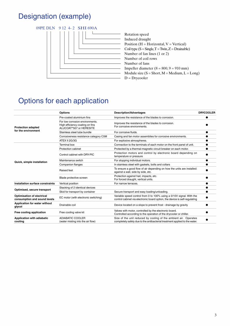
Designation(example)09PE DLN 9 12 4- 2 SHI 690A
Rotation speedInduced draughtPosition (H = Horizontal, V = Vertical)Coil type (S = Single, T = Twin, Z = Drainable)Number of fan lines (1 or 2)Number of coil rowsNumber of fansImpeller diameter (8 = 800, 9 = 910 mm)Module size (S = Short, M = Medium, L = Long)D = Drycooler
Options for each applicationOptions Description/Advantages DRYCOOLER
Protection adaptedfor the environment
Pre-coatedaluminiumfins Improvestheresistanceofthebladestocorrosion. ●Forlowcorrosionenvironments. Highefficiencycoatingonfins ALUCOAT®507orHERESITE
Improvestheresistanceofthebladestocorrosion.Forcorrosiveenvironments. ●
Stainless steel tube bundle Forcorrosivefluids. ●CorrosivenessresistancecategoryC5M Casingandfanmotorassembliesforcorrosiveenvironments. ●ATEXII2G/3G Forexplosiveatmospheres. ●
Quick, simple installation
Terminalbox Connection to the terminals of each motor on the front panel of unit. ●Protection cabinet Protected by a thermal-magnetic circuit breaker on each motor. ●
ControlcabinetwithDRY-PIC Protection motors and control by electronic board depending on temperature or pressure ●
Maintenanceswitch Forstoppingindividualmotors. ●Companionflanges Instainlesssteelwithgaskets,boltsandcollars ●
Raised feet Toensureagoodflowofairdependingonhowtheunitsareinstalled:againstawall,sidebyside,etc. ●
Bladeprotectivescreen Protection against hail, impacts, etc.Forforceddraught,verticalunits. ●
Installation surface constraints Verticalposition Fornarrowterraces. ●
Optimised, secure transportStackingof2identicaldevices ●Skid for transport by container Securetransportandeasyloading/unloading. ●
Optimisation of electrical consumption and sound levels ECmotor(withelectronicswitching) Variablespeedcontrolfrom0to100%usinga0/10Vsignal.Withthe
controlcabinetviaelectronicboardoption,thedeviceisself-regulating ●
Application for water without glycol Drainable coil Devicelocatedonaslopetopreventfrost-drainagebygravity ●
Free cooling application Freecoolingvalvekit Valveswithmotor,controlledbytheelectronicboard.Controlled according to the operation of the drycooler or chiller. ●
Application with adiabatic cooling
ADIABATICCOOLER(watermistingintotheairflow)
Size of the unit reduced by cooling of the ambient air. Operatescompletelysafelyduetotheantibacterialtreatmentappliedtothewater. ●

4
ElectricalspecificationsI : maximum input current P : maximum power inputThe currents and power actually absorbed depend on the operation point and will be indicated in detail when the unit is selected.
AC MOTORS EC MOTORS
Speed 900 690 890 6801000
Wiring Δ Y Δ YI(A) P(kW) I(A) P(kW) I(A) P(kW) I(A) P(kW) I(A) P(kW)
9010-1 5,3 2,65 3 1,84 3,9 2,13 2,3 1,33 4,4 2,98
9020-1 10,6 5,3 6 3,68 7,8 4,26 4,6 2,66 8,8 5,96
9030-1 15,9 7,95 9 5,52 11,7 6,39 6,9 3,99 13,2 8,94
9040-1 21,2 10,6 12 7,36 15,6 8,52 9,2 5,32 17,6 11,92
9050-1 26,5 13,25 15 9,2 19,5 10,65 11,5 6,65 22 14,9
9040-2 21,2 10,6 12 7,36 15,6 8,52 9,2 5,32 17,6 11,92
9060-2 31,8 15,9 18 11,04 23,4 12,78 13,8 7,98 26,4 17,88
9080-2 42,4 21,2 24 14,72 31,2 17,04 18,4 10,64 35,2 23,84
9100-2 53 26,5 30 18,4 39 21,3 23 13,3 44 29,8
9120-2 63,6 31,8 36 22,08 46,8 25,56 27,6 15,96 52,8 35,76
9140-2 74,2 37,1 42 25,76 54,6 29,82 32,2 18,62 61,6 41,72
AC MOTORS EC MOTORS
Speed 900 700 690 560 425 300510 (E8B) 740 (E8A)
Wiring Δ Y Δ Y Δ YI(A) P(kW) I(A) P(kW) I(A) P(kW) I(A) P(kW) I(A) P(kW) I(A) P(kW) I(A) P(kW) I(A) P(kW)
8010-1 3,65 1,98 2,4 1,43 2,1 0,895 1,05 0,56 0,42 0,194 0,35 0,075 0,49 0,298 1,4 0,918
8020-1 7,3 3,96 4,8 2,86 4,2 1,79 2,1 1,12 0,84 0,388 0,7 0,15 0,98 0,596 2,8 1,836
8030-1 10,95 5,94 7,2 4,29 6,3 2,685 3,15 1,68 1,26 0,582 1,05 0,225 1,47 0,894 4,2 2,754
8040-1 14,6 7,92 9,6 5,72 8,4 3,58 4,2 2,24 1,68 0,776 1,4 0,3 1,96 1,192 5,6 3,672
8050-1 18,25 9,9 12 7,15 10,5 4,475 5,25 2,8 2,1 0,97 1,75 0,375 2,45 1,49 7 4,59
8060-1 21,9 11,88 14,4 8,58 12,6 5,37 6,3 3,36 2,52 1,164 2,1 0,45 2,94 1,788 8,4 5,508
8040-2 14,6 7,92 9,6 5,72 8,4 3,58 4,2 2,24 1,68 0,776 1,4 0,3 1,96 1,192 5,6 3,672
8060-2 21,9 11,88 14,4 8,58 12,6 5,37 6,3 3,36 2,52 1,164 2,1 0,45 2,94 1,788 8,4 5,508
8080-2 29,2 15,84 19,2 11,44 16,8 7,16 8,4 4,48 3,36 1,552 2,8 0,6 3,92 2,384 11,2 7,344
8100-2 36,5 19,8 24 14,3 21 8,95 10,5 5,6 4,2 1,94 3,5 0,75 4,9 2,98 14 9,18
8120-2 43,8 23,76 28,8 17,16 25,2 10,74 12,6 6,72 5,04 2,328 4,2 0,9 5,88 3,576 16,8 11,016
8140-2 51,1 27,72 33,6 20,02 29,4 12,53 14,7 7,84 5,88 2,716 4,9 1,05 6,86 4,172 19,6 12,852
5
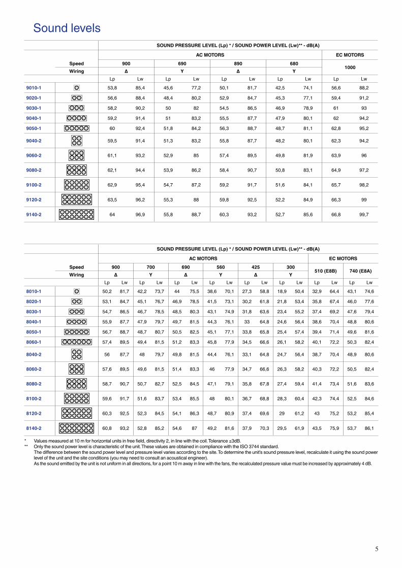
SoundlevelsSOUND PRESSURE LEVEL (Lp) * / SOUND POWER LEVEL (Lw)** - dB(A)
AC MOTORS EC MOTORS
Speed 900 690 890 6801000
Wiring Δ Y Δ YLp Lw Lp Lw Lp Lw Lp Lw Lp Lw
9010-1 53,8 85,4 45,6 77,2 50,1 81,7 42,5 74,1 56,6 88,2
9020-1 56,6 88,4 48,4 80,2 52,9 84,7 45,3 77,1 59,4 91,2
9030-1 58,2 90,2 50 82 54,5 86,5 46,9 78,9 61 93
9040-1 59,2 91,4 51 83,2 55,5 87,7 47,9 80,1 62 94,2
9050-1 60 92,4 51,8 84,2 56,3 88,7 48,7 81,1 62,8 95,2
9040-2 59,5 91,4 51,3 83,2 55,8 87,7 48,2 80,1 62,3 94,2
9060-2 61,1 93,2 52,9 85 57,4 89,5 49,8 81,9 63,9 96
9080-2 62,1 94,4 53,9 86,2 58,4 90,7 50,8 83,1 64,9 97,2
9100-2 62,9 95,4 54,7 87,2 59,2 91,7 51,6 84,1 65,7 98,2
9120-2 63,5 96,2 55,3 88 59,8 92,5 52,2 84,9 66,3 99
9140-2 64 96,9 55,8 88,7 60,3 93,2 52,7 85,6 66,8 99,7
SOUND PRESSURE LEVEL (Lp) * / SOUND POWER LEVEL (Lw)** - dB(A)
AC MOTORS EC MOTORS
Speed 900 700 690 560 425 300510 (E8B) 740 (E8A)
Wiring Δ Y Δ Y Δ YLp Lw Lp Lw Lp Lw Lp Lw Lp Lw Lp Lw Lp Lw Lp Lw
8010-1 50,2 81,7 42,2 73,7 44 75,5 38,6 70,1 27,3 58,8 18,9 50,4 32,9 64,4 43,1 74,6
8020-1 53,1 84,7 45,1 76,7 46,9 78,5 41,5 73,1 30,2 61,8 21,8 53,4 35,8 67,4 46,0 77,6
8030-1 54,7 86,5 46,7 78,5 48,5 80,3 43,1 74,9 31,8 63,6 23,4 55,2 37,4 69,2 47,6 79,4
8040-1 55,9 87,7 47,9 79,7 49,7 81,5 44,3 76,1 33 64,8 24,6 56,4 38,6 70,4 48,8 80,6
8050-1 56,7 88,7 48,7 80,7 50,5 82,5 45,1 77,1 33,8 65,8 25,4 57,4 39,4 71,4 49,6 81,6
8060-1 57,4 89,5 49,4 81,5 51,2 83,3 45,8 77,9 34,5 66,6 26,1 58,2 40,1 72,2 50,3 82,4
8040-2 56 87,7 48 79,7 49,8 81,5 44,4 76,1 33,1 64,8 24,7 56,4 38,7 70,4 48,9 80,6
8060-2 57,6 89,5 49,6 81,5 51,4 83,3 46 77,9 34,7 66,6 26,3 58,2 40,3 72,2 50,5 82,4
8080-2 58,7 90,7 50,7 82,7 52,5 84,5 47,1 79,1 35,8 67,8 27,4 59,4 41,4 73,4 51,6 83,6
8100-2 59,6 91,7 51,6 83,7 53,4 85,5 48 80,1 36,7 68,8 28,3 60,4 42,3 74,4 52,5 84,6
8120-2 60,3 92,5 52,3 84,5 54,1 86,3 48,7 80,9 37,4 69,6 29 61,2 43 75,2 53,2 85,4
8140-2 60,8 93,2 52,8 85,2 54,6 87 49,2 81,6 37,9 70,3 29,5 61,9 43,5 75,9 53,7 86,1
* Valuesmeasuredat10mforhorizontalunitsinfreefield,directivity2,inlinewiththecoil.Tolerance±3dB.** Onlythesoundpowerlevelischaracteristicoftheunit.ThesevaluesareobtainedincompliancewiththeISO3744standard. Thedifferencebetweenthesoundpowerlevelandpressurelevelvariesaccordingtothesite.Todeterminetheunit’ssoundpressurelevel,recalculateitusingthesoundpower
leveloftheunitandthesiteconditions(youmayneedtoconsultanacousticalengineer). Asthesoundemittedbytheunitisnotuniforminalldirections,forapoint10mawayinlinewiththefans,therecalculatedpressurevaluemustbeincreasedbyapproximately4dB.

6
DimensionsHorizontal Position - Induced Draught
AB
CD
E
1 40
0 m
ax55
0***
F
Unitshownhas2fanlines-no.ofmotorsbetweenthefeetisnotcontractuallybinding* forunitswithinput/outputtubesontheoppositeside** standard feet
No. of motors 1 2 3 4 5 6 4 6 8 10 12 14
DSN S module
A - - - - 1840 1840 - - - 1840 1840 1840B - - - - 2790 3740 - - - 2790 3740 4690C 830 1780 2730 3680 4630 5580 1780 2730 3680 4630 5580 6530D 950 1900 2850 3800 4750 5700 1900 2850 3800 4750 5700 6650Max empty weight without options +/-10% (kg) 233 369 503 666 809 928 638 875 1135 1393 1617 1874
DMN M module
A - - - 3140 3140 - - 3140 3140 4740 3140B - - - - 4740 - - - 4740 - 7940C 1480 3080 4680 6280 7880 3080 4680 6280 7880 9480 11080D 1600 3200 4800 6400 8000 3200 4800 6400 8000 9600 11200Max empty weight without options +/-10% (kg) 314 523 712 958 1183 918 1298 1645 2029 2388 2772
DLN L module
A - - - 3740 3740 - - 3740 3740 5640B - - - - 5640 - - - 5640 -C 1780 3680 5580 7480 9380 3680 5580 7480 9380 11280D 1900 3800 5700 7600 9500 3800 5700 7600 9500 11400Max empty weight without options +/-10% (kg) 352 599 846 1110 1373 1036 1474 1929 2384 2806
AllE 1240 2360F 1280 2400
Dimensions in mm.
Vertical position
A
BC
D
E
H
1 0671 110
*
F
Unitshownhas2fanlines-no.ofmotorsbetweenthefeetisnotcontractuallybinding* forunitswithinput/outputtubesontheoppositeside

7
No. of motors 1 2 3 4 5 6 4 6 8 10 12 14
DSN S module
A - - - 1840 1840 1840 - - 1840 1840 1840 1840B - - - - 2790 3740 - - - 2790 3740 4690C - - - - - - - - - - - -D - - - - - - - - - - - -E 830 1780 2730 3680 4630 5580 1780 2730 3680 4630 5580 6530F 950 1900 2850 3800 4750 5700 1900 2850 3800 4750 5700 6650Max empty weight without options +/-10% (kg) 282 419 554 705 915 1039 684 922 1181 1497 1727 1983
DMN M module
A - - 1540 1540 1540 - 1540 1540 1540 3140 3140B - - 3140 4740 3140 - 3140 4740 3140 6340 4740C - - - - 4740 - - - 4740 - 6340D - - - - 6340 - - - 6340 - 7940E 1480 3080 4680 6280 7880 3080 4680 6280 7880 9480 11080F 1600 3200 4800 6400 8000 3200 4800 6400 8000 9600 11200Max empty weight without options +/-10% (kg) 356 558 835 1046 1339 927 1383 1734 2187 2464 2920
DLN L module
A - - 1840 1840 1840 - 1840 1840 1840 3740B - - 3740 5640 3740 - 3740 5640 3740 7540C - - - - 5640 - - - 5640 -D - - - - 7540 - - - 7540 -E 1780 3680 5580 7480 9380 3680 5580 7480 9380 11280F 1900 3800 5700 7600 9500 3800 5700 7600 9500 11400Max empty weight without options +/-10% (kg) 399 639 972 1204 1537 1053 1572 1986 2501 2842
All H 1375 2495
Dimensions in mm.
Installation recommendations ■ These units are designed to operate outside.
When starting up, frost and snow could adversely affect the operation of horizontal units.
As a general measure, all steps should be taken to avoid the risk of air recycling. This is especially important when the installation comprises several units.
It is not recommended to install units near the hot air extraction duct outlet or close to deciduous plants (this could cause fouling).
■ A horizontal unit must have a surrounding free area of 1.5 m. Where the use of anti-vibration mounts is required, use a rigid frame which locks the feet together..
■ A vertical unit should preferably be placed parallel to the direction of the wind. It is not recommended for use with low fan rotation speeds. In addition, we recommend that these units be stabilised using braces connecting their two upper ends to fixed supports (wall or framework).
■ If speed regulators other than those recommended by the manufacturer are used, check that these are compatible with the electric motors.
■ Commissioning and maintenance: refer to the instruction manual.
■ These units comply with the European directives. The installer is responsible for ensuring the compliance of
the installation. The installer must ensure safety and protective devices (emergency stop, shut-off valves, lightning protection, etc.) are put in place and are accessible.

OrderNo.:10030,02.2017-SupersedesorderNo.:10030,11.2015. ManufacturedforCarrierinFrance.Themanufacturerreservestherighttochangeanyproductspecificationswithoutnotice. PrintedintheEuropeanUnion.
www.eurovent-certification.comwww.certiflash.com