performance · engine - 2az-fe engine 01meg02y valve timing : intake valve opening angle: exhaust...
TRANSCRIPT
NEW MODEL OUTLINE
01MMO40Y01MMO39Y
Torque(N.m) (ft.lbf)
240
220
200
180
160
140
180
160
140
120
100
1000
Output(HP) (kW)
180
160
140
120
100
80
60
40
20
0
140
120
100
80
60
40
20
0
2000 3000 4000 5000 6000 7000
Engine Speed (rpm)
2AZ-FE Engine 2GR-FE Engine
Torque(N.m) (ft.lbf)
340
320
300
280
260
240
260
240
220
200
180
1000
Output(HP) (kW)280
260
240
220
100
80
60
40
20
0
140
120
100
80
60
40
20
0
2000 3000 4000 5000 6000 7000
Engine Speed (rpm)
200
180
160
140
120
200
180
160
MO-29
PERFORMANCE
Power Train
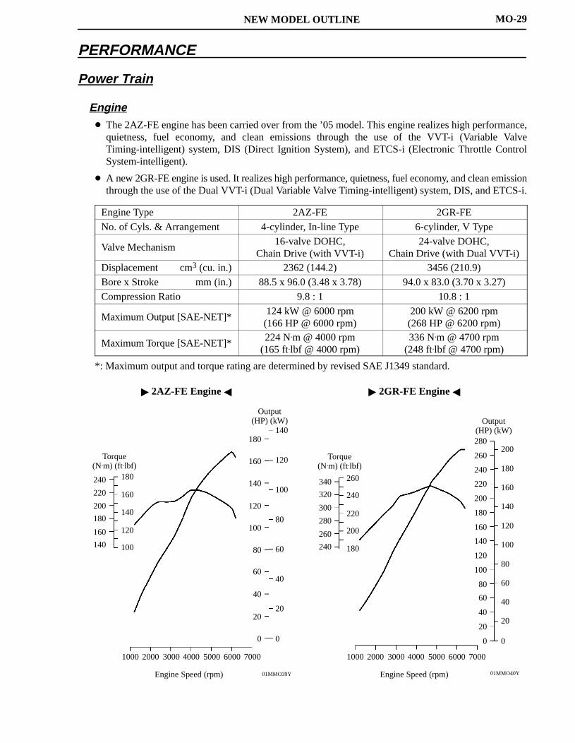
Engine The 2AZ-FE engine has been carried over from the ’05 model. This engine realizes high performance,
quietness, fuel economy, and clean emissions through the use of the VVT-i (Variable ValveTiming-intelligent) system, DIS (Direct Ignition System), and ETCS-i (Electronic Throttle ControlSystem-intelligent).
A new 2GR-FE engine is used. It realizes high performance, quietness, fuel economy, and clean emissionthrough the use of the Dual VVT-i (Dual Variable Valve Timing-intelligent) system, DIS, and ETCS-i.
Engine Type 2AZ-FE 2GR-FE
No. of Cyls. & Arrangement 4-cylinder, In-line Type 6-cylinder, V Type
Valve Mechanism16-valve DOHC,
Chain Drive (with VVT-i)24-valve DOHC,
Chain Drive (with Dual VVT-i)Displacement cm3 (cu. in.) 2362 (144.2) 3456 (210.9)
Bore x Stroke mm (in.) 88.5 x 96.0 (3.48 x 3.78) 94.0 x 83.0 (3.70 x 3.27)
Compression Ratio 9.8 : 1 10.8 : 1
Maximum Output [SAE-NET]*124 kW @ 6000 rpm(166 HP @ 6000 rpm)
200 kW @ 6200 rpm(268 HP @ 6200 rpm)
Maximum Torque [SAE-NET]*224 N.m @ 4000 rpm
(165 ft.lbf @ 4000 rpm)336 N.m @ 4700 rpm
(248 ft.lbf @ 4700 rpm)
*: Maximum output and torque rating are determined by revised SAE J1349 standard.

NEW MODEL OUTLINE
01NMO87Y
01NMO86Y
Four-wheel Drive Lock Switch
Electric Control CouplingPropeller Shaft
Transfer
Engine
Transaxle
Front Differential
Control Current
4WD ECU
Rear Differential
Speed Sensor
Yaw Rate & Deceleration Sensor
Steering Angle Sensor
ECM
System Configuration Diagram
MO-30
Transaxle
The U140F and U241E 4-speed automatic transaxles have been carried over from the ’05 model.
New U151E and U151F 5-speed automatic transaxles are used.
A new GF1A transfer is used.
Transaxle Type4-speed Automatic 5-speed Automatic
Transaxle TypeU140F U241E U151F U151E
Transfer Type GF1A — GF1A —
Combination with Engine 2AZ-FE 2GR-FE
Drive Type 4WD 2WD 4WD 2WD
1st 3.938 3.943 4.235
2nd 2.194 2.197 2.360
Gear 3rd 1.411 1.413 1.517 GearRatio* 4th 1.019 1.020 1.047
5th — — 0.756
Reverse 3.141 3.145 3.378
*: Counter Gear Ratio Included
Active Torque Control 4WD System
A new active torque control 4WD system with an electric control coupling is used.
The active torque control 4WD system, which has an electric control coupling in the front part of the reardifferential, transmits torque to the rear wheels when needed, and only in the amount needed, based oninformation provided by various sensors.
By operating the four-wheel drive lock switch provided on the instrument panel, the driver can select thefollowing modes: the AUTO mode to optimally control the torque that is transmitted to the rear wheels,and the LOCK mode that locks the torque that is transmitted to the rear wheels to the maximum amount.

NEW MODEL OUTLINE
01MCH100Y
MO-31
Chassis
Front Suspension Rear Suspension
TypeMacPherson Strut TypeIndependent Suspension
TypeDouble Wishbone TypeIndependent Suspension
Steering
TypeGear Type
EPS (Electronic Power Steering)Rack & Pinion
Brake
Front Brake Type Ventilated Disc
Front Rotor Size15 inch: 275 x 25 mm (10.82 x 0.87 in.)*1
16 inch: 296 x 28 mm (11.84 x 1.10 in.)*2
Rear Brake Type Solid Disc
Rear Rotor Size 15 inch: 281 x 12 mm (11.24 x 0.48 in.)
Parking BrakeType
Lever Type
Brake ControlABS (Anti-lock Brake System) with EBD (Electronic Brake force Distribution) &Brake Assist & TRAC (Traction Control) & Hill-start Assist Control*3 & DAC(Downhill Assist Control)*3 & VSC (Vehicle Stability Control)*4
*1: 2AZ-FE Engine Models with Rear No. 1 Seat Only*2: 2GR-FE Engine Models and Models with Rear No. 2 Seat*3: Standard Equipment on 2GR-FE Engine Models and Models with Rear No. 2 Seat*4: 2WD models have been provided with Auto LSD (Limited Slip Differential).
NEW MODEL OUTLINE
01NMO88Y 01NMO89Y
Standstill
’06 Model
Slow Backward Movement
’05 Model
MO-32
Enhanced VSC System
The enhanced VSC (Vehicle Stability Control) system is standard equipment on all models.
In addition to the ABS, TRAC, and VSC controls provided by the conventional system, the enhancedVSC system effects cooperative control with the EPS (Electric Power Steering) and active torque control4WD system in order to realize excellent driving stability and maneuverability.
See CH-92 for details on the enhanced VSC system.
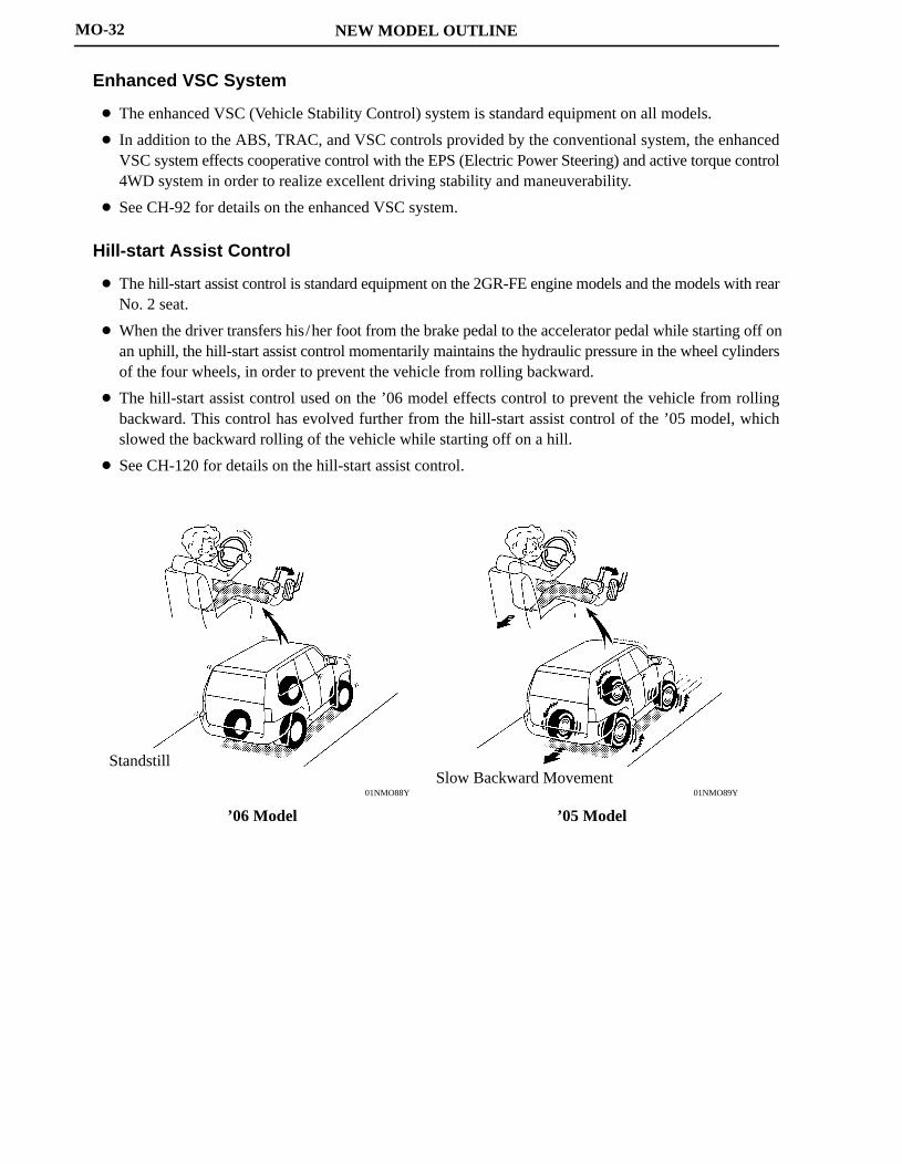
Hill-start Assist Control
The hill-start assist control is standard equipment on the 2GR-FE engine models and the models with rearNo. 2 seat.
When the driver transfers his/her foot from the brake pedal to the accelerator pedal while starting off onan uphill, the hill-start assist control momentarily maintains the hydraulic pressure in the wheel cylindersof the four wheels, in order to prevent the vehicle from rolling backward.
The hill-start assist control used on the ’06 model effects control to prevent the vehicle from rollingbackward. This control has evolved further from the hill-start assist control of the ’05 model, whichslowed the backward rolling of the vehicle while starting off on a hill.
See CH-120 for details on the hill-start assist control.

ENGINE
ENGINE - 2AZ-FE ENGINE
01NEG49Y
01NEG50Y
EG-2
2AZ-FE ENGINE
DESCRIPTION
The 2AZ-FE engine is an in-line, 4-cylinder, 2.4-liter, 16-valve DOHC engine. This engine uses the VVT-i(Variable Valve Timing-intelligent) system, DIS (Direct Ignition System), ETCS-i (Electronic ThrottleControl System-intelligent). It has been developed to realize high performance, quietness, fuel economy andclean emission.

ENGINE - 2AZ-FE ENGINE
01MEG02Y
Valve Timing : Intake Valve Opening Angle: Exhaust Valve Opening Angle
VVT-i OperationRange
VVT-i OperationRange
TDC3 3
43
65
25
45
BDC
EG-3
Engine Specifications
No. of Cyls. & Arrangement 4-cylinder, In-line
Valve Mechanism 16-valve DOHC, Chain Drive (with VVT-i)
Combustion Chamber Pentroof Type
Manifolds Cross-flow
Fuel System SFI
Ignition System DIS
Displacement cm3 (cu. in.) 2362 (144.1)
Bore x Stroke mm (in.) 88.5 x 96.0 (3.48 x 3.78)
Compression Ratio 9.8 : 1
Max. Output*1 (SAE-NET) 124 kW @ 6000 rpm (166 HP @ 6000 rpm)
Max. Torque*1 (SAE-NET) 224 N.m @ 4000 rpm (165 ft-lbf @ 4000 rpm)
IntakeOpen 3 - 43 BTDC
Valve Timing
IntakeClose 65 - 25 ABDC
Valve Timing
ExhaustOpen 45 BBDC
ExhaustClose 3 ATDC
Firing Order 1 - 3 - 4 - 2
Research Octane Number 91 or higher
Octane Rating 87 or higher
Oil Grade ILSAC
Tailpipe Emission Regulation ULEV-II, SFTP
Evaporative Emission Regulation LEV-II, ORVR
Engine Service Mass*2 (Reference) kg (lb) 138 (304.2)
*1: Maximum output and torque rating is determined by revised SAE J1349 standard.*2: Weight shows the figure with oil and water fully filled.

ENGINE - 2AZ-FE ENGINEEG-4
FEATURES OF 2AZ-FE ENGINE
The 2AZ-FE engine has achieved the following performance through the use of the items listed below.
(1) High performance and reliability
(2) Low noise and vibration
(3) Lightweight and compact design
(4) Good serviceability
(5) Clean emission and fuel economy
Section Item (1) (2) (3) (4) (5)
Engine
A cylinder block made of aluminum alloy along with amagnesium alloy die-cast cylinder head cover is used.
EngineProper A taper squish shape is used for the combustion chamber. p
A resin gear balance shaft is used.
V lA timing chain and chain tensioner are used.
ValveMechanism
The shim-less type valve lifters are used. Mechanism
The VVT-i system is used.
A chacoal filter is used in the air cleaner cap.
Intake and Intake manifold made of plastic is used. Intake andExhaustS
The linkless-type throttle body is used.
System A thin-wall ceramic TWC (Three-Way Catalytic converter)is used.
The fuel returnless system is used.
FuelSystem
Quick connectors are used to connect the fuel hose with thefuel pipe.
System12-hole type fuel injectors with high atomizing performanceare used.
IgnitionSystem
Iridium-tipped spark plugs are used.
ChargingSystem
The segment conductor type generator is used.
StartingSystem
PS (Planetary reduction-Segment conductor motor) typestarter is used.
The ETCS-i is used.
EngineControl
The DIS (Direct Ignition System) makes ignition timingadjustment unnecessary.
ControlSystem The non-contact type sensor is used in the throttle position
sensor.
The planar type air-fuel ratio sensor is used.

ENGINE - 2AZ-FE ENGINE
DR011EG20
Cylinder Head Cover
Cylinder Head Cover Gasket
02AEG02Y02AEG01Y
CylinderBore Side
Front
OuterSide
Shim
A
A
A - A Cross Section
EG-5
ENGINE PROPER
1. Cylinder Head Cover
A lightweight magnesium alloy die-castcylinder head cover is used.
Acrylic rubber, which excels in heat resistanceand reliability, is used for the cylinder headcover gasket.
2. Cylinder Head Gasket
A steel-laminate type cylinder head gasket is used. A shim has been added around the cylinder bore toincrease the sealing surface, thus improving the sealing performance and durability.

ENGINE - 2AZ-FE ENGINE
208EG67DR011EG21
Exhaust Side
Intake Side
A
A
A - A Cross Section
Injector
INEX
BypassPassage
Taper Squish
EG-6
3. Cylinder Head
Through the adoption of the taper squish combustion chamber, the engine knocking resistance and fuelefficiency have been improved.
An upright intake port is used to improve the intake efficiency.
Installing the injectors in the cylinder head enables the injectors inject fuel as close as possible to thecombustion chamber. This prevents the fuel from adhering to the intake port walls, which reduces HCexhaust emissions.
The routing of the water jacket in the cylinder head has been optimized to realize the high coolingperformance. In addition, a water bypass passage has been provided below the exhaust ports to reduce thenumber of parts and the weight.

ENGINE - 2AZ-FE ENGINE
DR011EG2201NEG26Y
Air Flow During Engine Revolution
Water PumpSwirl Chamber
CrankshaftBearing Cap
Plastic RegionTightening Bolts
Thermostat Housing
Air ConditioningCompressor Brackets
Air Passage Holes
Air Flow
NOTICE
Never attempt to machine the cylinder because it has a thin liner thickness.
EG-7
4. Cylinder Block
Lightweight aluminum alloy is used for the cylinder block.
By producing the thin cast-iron liners and cylinder block as a unit, compaction is realized.
Air passage holes are provided in the crankshaft bearing area of the cylinder block. As a result, the air atthe bottom of the cylinder flows smoother, and pumping loss (back pressure at the bottom of the pistongenerated by the piston’s reciprocal movement) is reduced to improve the engine’s output.
The oil filter and the air conditioning compressor brackets are integrated into the crankcase. Also, thewater pump swirl chamber and thermostat housing are integrated into the cylinder block.
ENGINE - 2AZ-FE ENGINE
01NEG27Y
Irregularly shapedouter castingsurface of liner
Cylinder Block
Liner
A
A
A - A Cross Section
01NEG28Y
Water JacketSpacer
Water Jacket
A - A Cross Section
A
A
EG-8
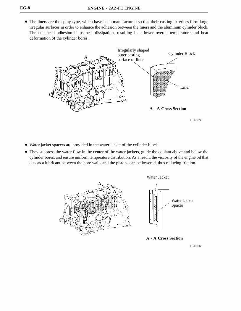
The liners are the spiny-type, which have been manufactured so that their casting exteriors form largeirregular surfaces in order to enhance the adhesion between the liners and the aluminum cylinder block.The enhanced adhesion helps heat dissipation, resulting in a lower overall temperature and heatdeformation of the cylinder bores.
Water jacket spacers are provided in the water jacket of the cylinder block.
They suppress the water flow in the center of the water jackets, guide the coolant above and below thecylinder bores, and ensure uniform temperature distribution. As a result, the viscosity of the engine oil thatacts as a lubricant between the bore walls and the pistons can be lowered, thus reducing friction.
ENGINE - 2AZ-FE ENGINE
01MEG01Y
Taper Squish Shape
: Resin Coating
240EG45
Plastic Region Tightening Bolts
EG-9
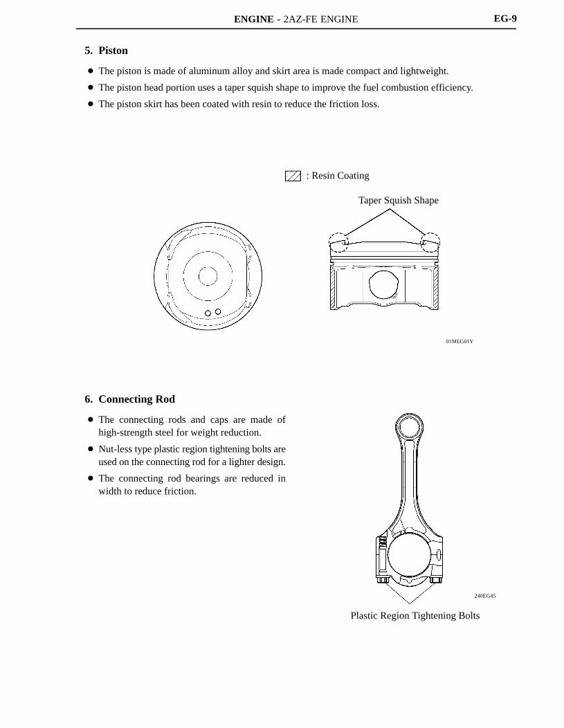
5. Piston
The piston is made of aluminum alloy and skirt area is made compact and lightweight.
The piston head portion uses a taper squish shape to improve the fuel combustion efficiency.
The piston skirt has been coated with resin to reduce the friction loss.
6. Connecting Rod
The connecting rods and caps are made ofhigh-strength steel for weight reduction.
Nut-less type plastic region tightening bolts areused on the connecting rod for a lighter design.
The connecting rod bearings are reduced inwidth to reduce friction.

ENGINE - 2AZ-FE ENGINE
01NEG31Y
No.1 JournalBalance Shaft Drive Gear
Oil Hole
Crank PinBalance Weight
01NEG32Y
: Resin Gear
Balance ShaftHousing
Balance Shaft No.1
Balance Shaft No.2
CrankshaftBalance Shaft Drive Gear
EG-10
7. Crankshaft
The forged crankshaft has 5 journals and 8 balance weights.
The crankshaft is made of forged steel.
Pin and journal fillets are roll-finished to maintain adequate strength.
The balance shaft drive gear is provided for the crankshaft.
8. Balance Shaft
General
A balance shaft is used to reduce vibrations.
The crankshaft directly drives the No. 1 balance shaft.
In addition, a resin gear is used on the driven side to suppress noise and offer lightweight design.
ENGINE - 2AZ-FE ENGINE
286EG71
Top Dead Center
Point of Max. Speed
Bottom Dead Center
Point ofMax. Speed
Point ofMax. Speed
90
286EG72
Inertial Force of CylindersNo.2 and No.3
Combined Inertial Force ofAll Cylinders
Unbalanced SecondaryInertial Force
Inertial Force of CylinderNo.1 and No.4
Force Inertial force that cannot be canceled
Crankshaft Angle
- 90 90 270
1800- 180
Inertial Force Generated by the In-line 4 Cylinders
286EG73
0 90 180 270
AB
CD
E
Inertial Force of Balancer
Crankshaft Angle
Secondary Inertial Force
Mass Direction ofBalance Shaft
Inertial Force ofBalancer
Mass Direction of Balance Shaft at Crankshaft Angle
EG-11
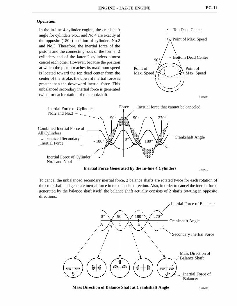
Operation
In the in-line 4-cylinder engine, the crankshaftangle for cylinders No.1 and No.4 are exactly atthe opposite (180) position of cylinders No.2and No.3. Therefore, the inertial force of thepistons and the connecting rods of the former 2cylinders and of the latter 2 cylinders almostcancel each other. However, because the positionat which the piston reaches its maximum speedis located toward the top dead center from thecenter of the stroke, the upward inertial force isgreater than the downward inertial force. Thisunbalanced secondary inertial force is generatedtwice for each rotation of the crankshaft.
To cancel the unbalanced secondary inertial force, 2 balance shafts are rotated twice for each rotation ofthe crankshaft and generate inertial force in the opposite direction. Also, in order to cancel the inertial forcegenerated by the balance shaft itself, the balance shaft actually consists of 2 shafts rotating in oppositedirections.

ENGINE - 2AZ-FE ENGINE
240EG46181EG10
VVT-i Controller
Intake Camshaft ExhaustCamshaft
ChainTensioner
Chain Damper
Chain Slipper
Camshaft
ValveLifter
Service Tip
The adjustment of the valve clearance is accomplished by selecting and replacing the appropriatevalve lifters.A total of 35 valve lifters are available in 0.02 mm (0.008 in.) increments, from 5.06 mm (0.199 in.)to 5.74 mm (0.226 in.). For details, refer to 2006 RAV4 Repair Manual (Pub. No. RM01M1U).
EG-12
VALVE MECHANISM
1. General
The VVT-i system is used to improve fuel economy, engine performance and reduce exhaust emissions.For details of VVT-i system, see page EG-48.
The intake and exhaust camshafts are driven by a timing chain.
Along with the increase in the amount of valve lift, the shim-less type valve lifter is used. This valve lifterincreases the cam contact surface.

ENGINE - 2AZ-FE ENGINE
181EG11
VVT-i ControllerIntake Camshaft
Timing Rotor
Exhaust Camshaft
Timing Sprocket
185EG25
181EG14
Cam Spring
Cam
PlungerSpring
ChainTensioner
Chain Damper
Oil Jet
Chain Tensioner
Chain Slipper
EG-13
2. Camshaft
The intake camshaft is provided with timing rotor to trigger the camshaft position sensor.
In conjunction with the adoption of the VVT-i system, an oil passage is provided in the intake camshaftin order to supply engine oil pressure to the VVT-i system.
A VVT-i controller has been installed on the front of the intake camshaft to vary the timing of the intakevalves.
3. Timing Chain
A roller chain with an 8 mm (0.315 in.) pitch is used to make the engine more compact.
The timing chain is lubricated by an oil jet.
The chain tensioner uses a spring and oil pressure to maintain proper chain tension at all times.
The chain tensioner suppresses noise generated by the timing chain.
A ratchet type non-return mechanism is used.
To achieve excellent serviceability, the chain tensioner is constructed so that it can be removed andinstalled from the outside of the timing chain cover.

ENGINE - 2AZ-FE ENGINE
208EG07
VVT-i Controller
Camshaft TimingOil Control Valve
Oil ReturnHole
Oil PumpOil Filter
ChainTensioner
01NEG33Y
BypassValve
ReliefValve
Main Oil Hole
Oil Filter
Oil Pump
Oil Strainer
ChainTensioner
Cylinder Head
ExhaustCamshaftJournal
Oil ControlValve
VVT-i Controller
Oil Pan
IntakeCamshaftJournal
CrankshaftJournal
CrankshaftPin
Oil Jet
Piston
CylinderBlock
BaranceShaft
TimingChain
EG-14
LUBRICATION SYSTEM
1. General
The lubrication circuit is fully pressurized and oil passes through an oil filter.
The trochoid gear type oil pump is chain-driven by the crankshaft.
The oil filter is attached downward from the crankcase to improve serviceability.
Along with the adoption of the VVT-i system, the cylinder head is provided with a VVT-i controller anda camshaft timing oil control valve. This system is operated by the engine oil.
Oil Circuit
ENGINE - 2AZ-FE ENGINE
01NEG34Y
Oil Jets
CheckValve Oil
Bottom Side View Oil Jet Cross Section
EG-15
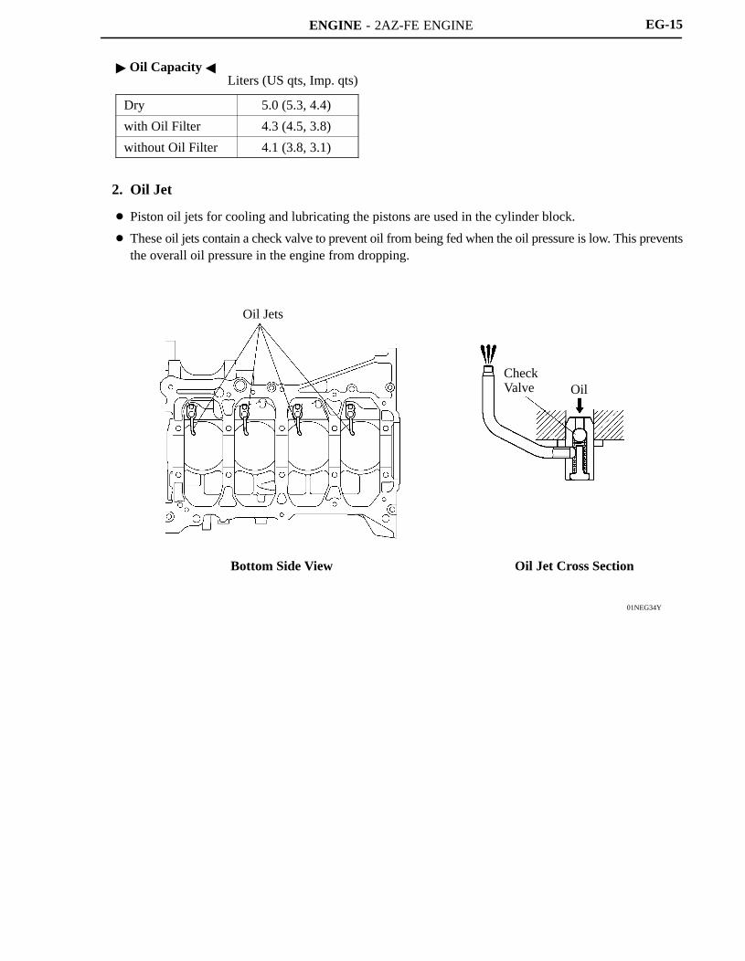
Oil Capacity Liters (US qts, Imp. qts)
Dry 5.0 (5.3, 4.4)
with Oil Filter 4.3 (4.5, 3.8)
without Oil Filter 4.1 (3.8, 3.1)
2. Oil Jet
Piston oil jets for cooling and lubricating the pistons are used in the cylinder block.
These oil jets contain a check valve to prevent oil from being fed when the oil pressure is low. This preventsthe overall oil pressure in the engine from dropping.
ENGINE - 2AZ-FE ENGINE
01NEG35Y
Throttle Body
To Heater Core
To Radiator
Thermostat
From Radiator
Water Pump
Bypass Passage
01NEG59Y
Bypass PassageCylinder Head
Water Pump
Cylinder Block
ThermostatReservoirTank
Radiator
ThrottleBody
Heater Core
EG-16
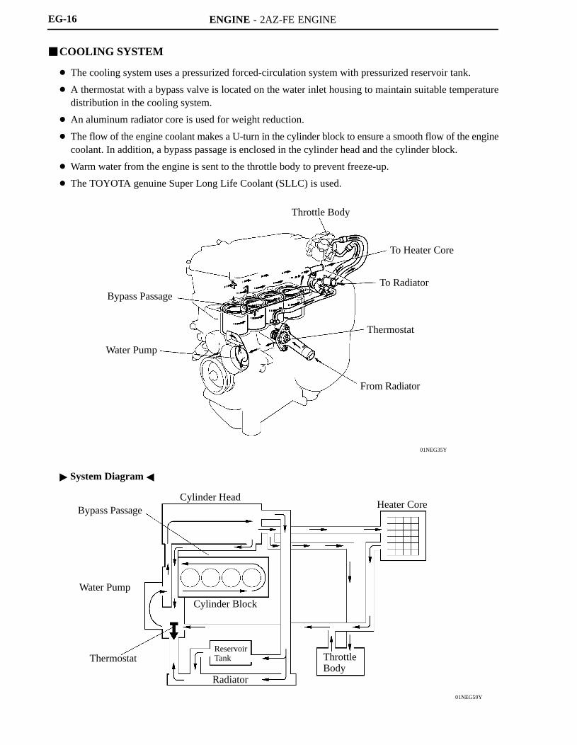
COOLING SYSTEM
The cooling system uses a pressurized forced-circulation system with pressurized reservoir tank.
A thermostat with a bypass valve is located on the water inlet housing to maintain suitable temperaturedistribution in the cooling system.
An aluminum radiator core is used for weight reduction.
The flow of the engine coolant makes a U-turn in the cylinder block to ensure a smooth flow of the enginecoolant. In addition, a bypass passage is enclosed in the cylinder head and the cylinder block.
Warm water from the engine is sent to the throttle body to prevent freeze-up.
The TOYOTA genuine Super Long Life Coolant (SLLC) is used.
System Diagram

ENGINE - 2AZ-FE ENGINE EG-17
Engine Coolant Specifications
EngineCoolant
Type
TOYOTA genuine Super Long Life Coolant(SLLC) or similar high quality ethyleneglycol based non-silicate, non-amine,non-nitrite and non-borate coolant withlong-life hybrid organic acid technology(coolant with long-life hybrid organic acidtechnology is a combination of lowphosphates and organic acids.) Do not useplain water alone.
Color Pink
Capacity M/T 6.6 (7.0, 5.8)CapacityLiters (US qts, Imp. qts) A/T 6.7 (7.1, 5.9)
Maintenance First Time 100,000 mile (160,000 km)MaintenanceIntervals Subsequent Every 50,000 mile (80,000 km)
Thermostat Opening Temperature C (F) 80 - 84 (176 - 183)
SLLC is pre-mixed (the U.S.A. models: 50 % coolant and 50 % deionized water, the Canada. models:55 % coolant and 45 % deionized water). Therefore, no dilution is needed when SLLC in the vehicle isadded or replaced.
If LLC is mixed with SLLC, the interval for LLC (every 25,000 miles / 40,000 km or 24 monthswhichever comes first) should be used.
You can also apply the new maintenance interval (every 50,000 miles / 80,000 km) to vehicles initiallyfilled with LLC (red-colored), if you use SLLC (pink-colored) for the engine coolant change.
ENGINE - 2AZ-FE ENGINE
01MEG32Y
Exhaust Manifold
Intake Manifold
Main Muffler
Sub Muffler
TWC
Air Cleaner
TWC
EG-18
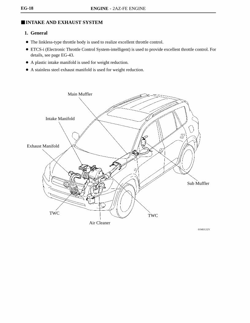
INTAKE AND EXHAUST SYSTEM
1. General
The linkless-type throttle body is used to realize excellent throttle control.
ETCS-i (Electronic Throttle Control System-intelligent) is used to provide excellent throttle control. Fordetails, see page EG-43.
A plastic intake manifold is used for weight reduction.
A stainless steel exhaust manifold is used for weight reduction.
ENGINE - 2AZ-FE ENGINE
01MEG10Y
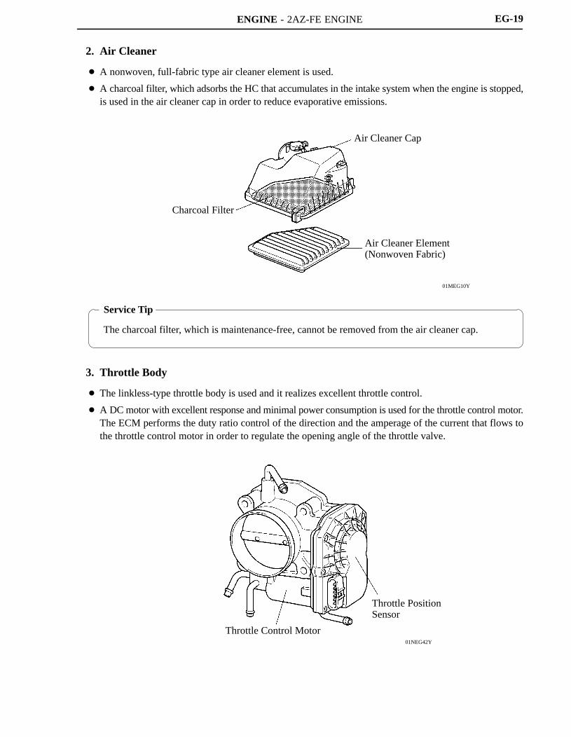
Charcoal Filter
Air Cleaner Cap
Air Cleaner Element(Nonwoven Fabric)
Service Tip
The charcoal filter, which is maintenance-free, cannot be removed from the air cleaner cap.
01NEG42Y
Throttle PositionSensor
Throttle Control Motor
EG-19
2. Air Cleaner
A nonwoven, full-fabric type air cleaner element is used.
A charcoal filter, which adsorbs the HC that accumulates in the intake system when the engine is stopped,is used in the air cleaner cap in order to reduce evaporative emissions.
3. Throttle Body
The linkless-type throttle body is used and it realizes excellent throttle control.
A DC motor with excellent response and minimal power consumption is used for the throttle control motor.The ECM performs the duty ratio control of the direction and the amperage of the current that flows tothe throttle control motor in order to regulate the opening angle of the throttle valve.

ENGINE - 2AZ-FE ENGINE
01NEG37Y
Mesh Type Gasket
01NEG38Y
TWC
EG-20
4. Intake Manifold
The intake manifold has been made of plastic to reduce the weight and the amount of heat transferred fromthe cylinder head. As a result, it has become possible to reduce the intake air temperature and improve theintake volumetric efficiency.
A mesh type gasket is used, in order to reduce the intake noise.
5. Exhaust Manifold
A stainless steel exhaust manifold is used for improving the warm-up of TWC (Three-Way Catalyticconverter) and for weight reduction.

ENGINE - 2AZ-FE ENGINE
01MEG33Y
Ball Joint
SpringGasket
Bolt
Sub Muffler
Ball JointMain Muffler
TWC
Ball Joint
EG-21
6. Exhaust Pipe
The exhaust pipe uses two ball joints in order to achieve a simple construction and ensured reliability.
The TWC can improve exhaust emission by optimizing the cell density and the wall thickness.

ENGINE - 2AZ-FE ENGINE
01MEG30Y
Fuel Pump Assembly Fuel Filter Pressure Regulator
Quick Connector
Injector
Fuel Tank
Canister
EG-22
FUEL SYSTEM
1. General
The fuel returnless system is used to reduce evaporative emissions.
A fuel cut control is used to stop the fuel pump when the SRS airbag is deployed in a front or side collision.For details, see page EG-53.
A quick connector is used in the fuel main pipe to improve serviceability.
The 12-hole type fuel injector is used.
The ORVR (On-board Refueling Vapor Recovery) system is used. For details, see page EG-54.

ENGINE - 2AZ-FE ENGINE
185EG16
PulsationDumper
Pressure Regulator
Fuel PumpAssembly
Fuel Tank
Fuel Filter
Fuel Pump
DR011EG18
EG-23
2. Fuel Returnless System
Fuel returnless system is used to reduce the evaporative emission. As shown below, by integrating the fuelfilter and pressure regulator with fuel pump assembly, the fuel return system in which the fuel returns fromthe engine area is discontinued and temperature rise inside the fuel tank is prevented.
3. Fuel Injector
The 12-hole type injector is used. By modifying itsinjector nozzle to a taper shape, this injector hasachieved high atomizing performance of fuel. Inaddition, the injector provides good performancewith the lightweight moving parts and theoptimized magnetic circuit.

ENGINE - 2AZ-FE ENGINE
165EG25
CamshaftPositionSensor
CrankshaftPositionSensor
VariousSensor
G2
NEECM
IGT1
IGT2
IGT3
IGT4
IGF
+B
Ignition Coil(with Igniter)
No.1 Cylinder
No.2 Cylinder
No.3 Cylinder
No.4 Cylinder
185EG38
0.7 mm(0.028 in.)
Iridium Tip
EG-24
IGNITION SYSTEM
1. General
A DIS (Direct Ignition System) is used. The DIS improves the ignition timing accuracy, reduceshigh-voltage loss, and enhances the overall reliability of the ignition system by eliminating the distributor.
The DIS in this engine is an independent ignition system which has one ignition coil (with igniter) for eachcylinder.
Iridium-tipped spark plugs are used.
2. Spark Plug
Iridium-tipped spark plugs are used to improve ignition performance while maintaining the same durabilityof the platinum-tipped spark plugs.
Specifications
DENSO SK20R11
NGK IFR6A11
Plug Gap1.0 - 1.1 mm
(0.039 - 0.043 in.)

ENGINE - 2AZ-FE ENGINE
206EG40
206EG41
206EG42
Stator SegmentConductor
Stator
Joined
Joined SegmentConductor System
SegmentConductor
Stator StatorConductorWire
Conductor Wire
A
A
A - A CrossSection
Segment Conductor Type Generator
B
B
B - B CrossSection
Conventional Type Generator
Winding System
Stator
SegmentConductor
Cross Section
Stator of Segment Conductor Type Generator
EG-25
CHARGING SYSTEM
1. Segment Conductor Type Generator
A compact and lightweight segment conductor type generator that generates high amperage output in ahighly efficient manner is used.
This generator has a joined segment conductor system in which multiple segment conductors are weldedtogether to form the stator. Compared to the conventional winding system, the electrical resistance isreduced due to the shape of the segment conductors, and their arrangement helps to make the generatorcompact.
Specifications
Type SE0
Rated Voltage 12 V
Rated Output 100 A
Initial Output Starting Speed Max. 1,500 rpm

ENGINE - 2AZ-FE ENGINE
01NEG45Y
Regulator
B
M
IG
RLO
L
Ignition Switch
To DischargeWarning Light
Generator
ECM
281EG13281EG12
Coil SpringPulley
Helical Coil Type One-way Clutch
EG-26
Wiring Diagram
2. Generator Pulley
A helical coil type one-way clutch is used on the generator pulley in order to reduce the load that acts onthe auxiliary equipment belt.
The pulley mounting nut and the generator pulley have been integrated to achieve a compact construction.

ENGINE - 2AZ-FE ENGINE
01NEG46Y
Armature
Surface Commutator
Permanent Magnet
Brush
Length
EG-27
STARTING SYSTEM
1. General
A compact and lightweight PS (Planetary reduction-Segment conductor motor) type starter is used.
Because the PS type starter contains an armature that uses square-shaped conductors, and its surfacefunctions as a commutator, it has resulted in both improving its output torque and reducing its overalllength.
In place of the field coil used in the conventional type starter, the PS type starter uses two types ofpermanent magnets: main magnets and interpolar magnets. The main magnets and interpolar magnetshave been efficiently arranged to increase the magnetic flux and to shorten the length of the yoke.
Specifications
Starter Type PS Type
Rating Output 1.7 kW
Rating Voltage 12 V
Length*1 mm (in.) 128 (5.04)
Weight g (lb) 2950 (6.50)
Rotational Direction*2 Counterclockwise
*1: Length from the mounted area to the rear end of the starter*2: Viewed from pinion side
ENGINE - 2AZ-FE ENGINE
206EG20
Conventional Type
A - ACross Section
(PS Type)
B - BCross Section
(Conventional Type)
B
B
A
A
Armature
ArmatureBrush
Commutator
Brush
Surface Commutator
Square-shapedConductor
Round-shapedConductor
PS Type
222EG15
Main Magnet Interpolar Magnet
YokeMain Magnet
Armature
Cross Section of Yoke
Magnetic Flux Generated byRelationship between Main Magnets
Magnetic Flux Generatedby Interpolar Magnets
NN
NS
S
S
EG-28
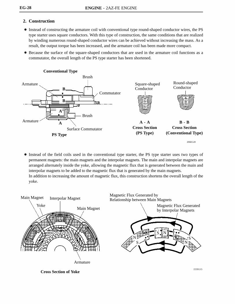
2. Construction
Instead of constructing the armature coil with conventional type round-shaped conductor wires, the PStype starter uses square conductors. With this type of construction, the same conditions that are realizedby winding numerous round-shaped conductor wires can be achieved without increasing the mass. As aresult, the output torque has been increased, and the armature coil has been made more compact.
Because the surface of the square-shaped conductors that are used in the armature coil functions as acommutator, the overall length of the PS type starter has been shortened.
Instead of the field coils used in the conventional type starter, the PS type starter uses two types ofpermanent magnets: the main magnets and the interpolar magnets. The main and interpolar magnets arearranged alternately inside the yoke, allowing the magnetic flux that is generated between the main andinterpolar magnets to be added to the magnetic flux that is generated by the main magnets.In addition to increasing the amount of magnetic flux, this construction shortens the overall length of theyoke.

ENGINE - 2AZ-FE ENGINE
240EG98
Idler Pulley for Automatic TensionerGenerator Pulley
Water Pump Pulley
Air ConditioningCompressor Pulley
Crankshaft Pulley
Idler Pulley
258RV77
Arm Idler Pulley
TensionerA - A Cross Section
A
A
EG-29
SERPENTINE BELT DRIVE SYSTEM
1. General
Accessory components are driven by a serpentine belt consisting of a single V-ribbed belt. It reduces theoverall engine length, weight and the number of engine parts.
An automatic tensioner eliminates the need for tension adjustment.
2. Automatic Tensioner
The automatic tensioner consists of an idler pulley and a tensioner. The idler pulley maintains belt tensionby the force of the spring that is located in the tensioner.
ENGINE - 2AZ-FE ENGINEEG-30
ENGINE CONTROL SYSTEM
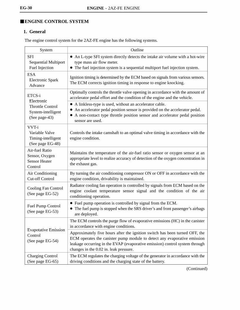
1. General
The engine control system for the 2AZ-FE engine has the following systems.
System Outline
SFI Sequential MultiportFuel Injection
An L-type SFI system directly detects the intake air volume with a hot-wiretype mass air flow meter.
The fuel injection system is a sequential multiport fuel injection system.
ESA Electronic Spark Advance
Ignition timing is determined by the ECM based on signals from various sensors.The ECM corrects ignition timing in response to engine knocking.
ETCS-i Electronic
Optimally controls the throttle valve opening in accordance with the amount ofaccelerator pedal effort and the condition of the engine and the vehicle.
Electronic Throttle ControlSystem-intelligent (See page-43)
A linkless-type is used, without an accelerator cable. An accelerator pedal position sensor is provided on the accelerator pedal. A non-contact type throttle position sensor and accelerator pedal position
sensor are used.
VVT-i Variable ValveTiming-intelligent (See page EG-48)
Controls the intake camshaft to an optimal valve timing in accordance with theengine condition.
Air-fuel Ratio Sensor, OxygenSensor HeaterControl
Maintains the temperature of the air-fuel ratio sensor or oxygen sensor at anappropriate level to realize accuracy of detection of the oxygen concentration inthe exhaust gas.
Air Conditioning Cut-off Control
By turning the air conditioning compressor ON or OFF in accordance with theengine condition, drivability is maintained.
Cooling Fan Control (See page EG-52)
Radiator cooling fan operation is controlled by signals from ECM based on theengine coolant temperature sensor signal and the condition of the airconditioning operation.
Fuel Pump Control (See page EG-53)
Fuel pump operation is controlled by signal from the ECM. The fuel pump is stopped when the SRS driver’s and front passenger’s airbags
are deployed.
Evapotative Emission
The ECM controls the purge flow of evaporative emissions (HC) in the canisterin accordance with engine conditions.
Evapotative EmissionControl (See page EG-54)
Approximately five hours after the ignition switch has been turned OFF, theECM operates the canister pump module to detect any evaporative emissionleakage occurring in the EVAP (evaporative emission) control system throughchanges in the 0.02 in. leak pressure.
Charging Control (See page EG-65)
The ECM regulates the charging voltage of the generator in accordance with thedriving conditions and the charging state of the battery.
(Continued)

ENGINE - 2AZ-FE ENGINE EG-31
System Outline
EngineImmobilizer*2
Prohibits fuel delivery and ignition if an attempt is made to start the engine withan invalid ignition key.
Diagnosis (See page EG-67)
When the ECM detects a malfunction, the ECM diagnoses and memorizes thefailed section.
Fail-safe (See page EG-67)
When the ECM detects a malfunction, the ECM stops or controls the engineaccording to the data already stored in memory.
*2: Models with Engine Immobilizer System
ENGINE - 2AZ-FE ENGINE
01MEG04Y
SENSORS ACTUATORS
MASS AIR FLOW METER
INTAKE AIR TEMPERATURESENSOR
ENGIEN COOLANTTEMPERATURE SENSOR
THROTTLE POSITIONSENSOR
CRANKSHAFT POSITIONSENSOR
CAMSHAFT POSITIONSENSOR
ACCELERATOR PEDALPOSITION SENSOR
AIR-FUEL RATIO SENSOR(Bank 1, Sensor 1)
HEATED OXYGEN SENSOR(Bank 1, Sensor 2)
KNOCK SENSOR
COMBINATION METER
Vehicle Speed Signal
IGNITION SWITCH
Ignition Signal Starter Signal
PARK/NEUTRAL POSITIONSWITCH
TRANSMISSION CONTROLSWITCH
CRUISE CONTROL SWITCH
VG
THA
THW
VTA1
VTA2
NE
G2
VPAVPA2
A1A
OX1B
KNK1
SPD
IGSWSTA
D, 2, L
R, P, N
3
CCS
ECM
#10
#20
#30
#40
IGT1 IGT4
IGF1
M
OC1
FC
HA1A
HT1B
SFI
No.1 INJECTOR
No.2 INJECTOR
No.3 INJECTOR
No.4 INJECTOR
ESA
IGNITION COILwith IGNITER
SPARK PLUGS
ETCS-i
THROTTLE CONTROLMOTOR
VVT-i
CAMSHAFT TIMING OILCONTROL VALVE
FUEL PUMP CONTROL
CIRCUIT OPENINGRELAY
AIR-FUEL RATIO ANDHEATED OXYGEN SENSORHEATER CONTROL
AIR-FUEL RATIO SENSORHEATER (Bank1, Sensor1)
HEATED OXYGEN SENSORHEATER (Bank1, Sensor2)
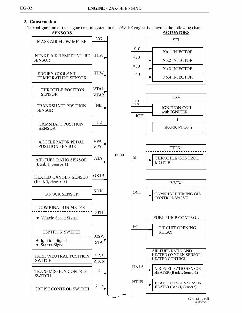
EG-32
2. ConstructionThe configuration of the engine control system in the 2AZ-FE engine is shown in the following chart.
(Continued)

ENGINE - 2AZ-FE ENGINE
01MEG05Y
DEFGGER SWITCH
TAIL LIGHT SWITCH
STOP LIGHT SWITCH
CURRENT SENSOR
CANISTER PUMP MODULE
CANISTER PRESSURESENSOR
TRANSPONDER KEY ECU*
AIRBAG SENSOR ASSEMBLY
EPS ECU
AIR CONDITIONING ECU
SKID CONTROL ECU
DLC3
BATTERY
ELS1
ELS3
STPST1-
THB
VCIB
PPMP
IMIIMO
CANH,CANL
TC
TACH
BATT
ECM
FANH
FANL
MPMP
VPMP
PRG
RLO
DF
MREL
+B
W
COOLING FAN CONTROL
COOLING FAN RELAY No.1
COOLING FAN RELAY No.2
COOLING FAN RELAY No.3
EVAPORATIVE EMISSIONCONTROL
CANISTER PUMP MODULE
LEAK DETECTION PUMP
VENT VALVE
GENERATOR
MAIN RELAY
COMBINATION METER
MIL
PURGE VSV
: CAN
EG-33
*: Models with Engine Immobilizer System

ENGINE - 2AZ-FE ENGINE
01MEG09Y
Accelerator PedalPosition Sensor
Generator
MILDLC3
Park/NeutralPosition Switch
IgnitionSwitch
Circuit Opening Relay ECM
Battery
ThrottlePositionSensor
ThrottleControlMotor
Purge VSV
Mass Air Flow Meter Intake Air Temperature
SensorCamshaft PositionSensorCamshaft
TimingOil ControlValve
Ignition Coilwith Igniter
Injector
Knock Sensor
EngineCoolantTemperatureSensor
Crankshaft PositionSensorCanister
Filter
Fuel Pump
Canister Pump Module Vent Valve Leak Detection Pump Canister Pressure Sensor
TWCs
Heated Oxygen Sensor(Bank 1, Sensor 2)
Air-fuel Ratio Sensor(Bank 1, Sensor 1)
EG-34
3. Engine Control System Diagram

ENGINE - 2AZ-FE ENGINE
01MEG31Y
DLC3Accelerator PedalPosition Sensor
Mass Air Flow Meter(Built-in Intake Air Temperature Sensor)
VSV (for EVAP)
Battery CurrentSensor
Fuel Pump
Canister Pump Module Vent Valve Leak Detection Pump Canister Pressure Sensor
ECMHeated Oxygen Sensor(Bank 1, Sensor 2)
Air Fuel Ratio Sensor(Bank 1, Sensor 1)
Camshaft TimingOil Control Valve
Injector Knock Sensor
Ignition Coil with Igniter
Throttle PositionSensor
Camshaft PositionSensor
Water TemperatureSensorCrakshaft Position
Sensor
EG-35
4. Layout of Main Components
ENGINE - 2AZ-FE ENGINEEG-36
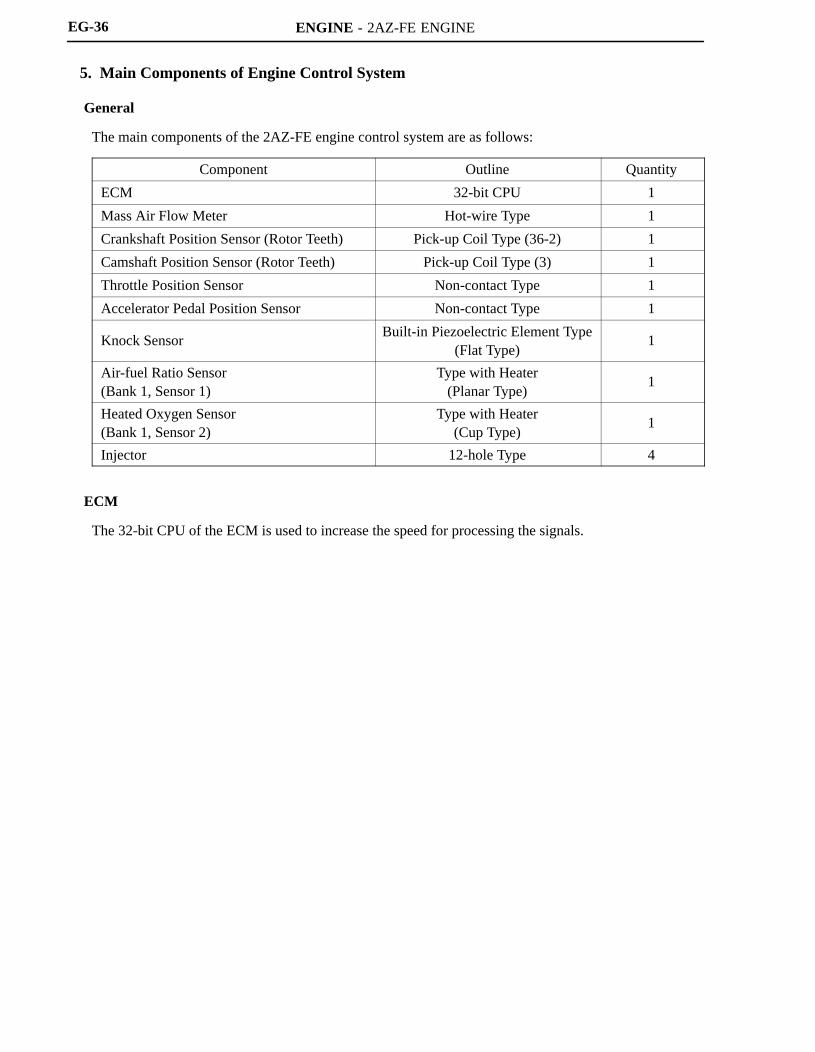
5. Main Components of Engine Control System
General
The main components of the 2AZ-FE engine control system are as follows:
Component Outline Quantity
ECM 32-bit CPU 1
Mass Air Flow Meter Hot-wire Type 1
Crankshaft Position Sensor (Rotor Teeth) Pick-up Coil Type (36-2) 1
Camshaft Position Sensor (Rotor Teeth) Pick-up Coil Type (3) 1
Throttle Position Sensor Non-contact Type 1
Accelerator Pedal Position Sensor Non-contact Type 1
Knock SensorBuilt-in Piezoelectric Element Type
(Flat Type)1
Air-fuel Ratio Sensor (Bank 1, Sensor 1)
Type with Heater(Planar Type)
1
Heated Oxygen Sensor (Bank 1, Sensor 2)
Type with Heater(Cup Type)
1
Injector 12-hole Type 4
ECM
The 32-bit CPU of the ECM is used to increase the speed for processing the signals.

ENGINE - 2AZ-FE ENGINE
00REG21Y
D13N11
Air-fuelRatio Sensor
A1A+
(3.3V)
A1A-(2.9V)
ECM
HeatedOxygenSensor
OX1B
EX1B
ECM
Air-fuel Ratio Sensor Circuit Heated Oxygen Sensor
: Air-fuel Ratio Sensor: Heated Oxygen Sensor
Air-fuel Ratio Sensor DataDisplayed on Hand-heldTester
4.2
2.2
11 (Rich) 14.7 19 (Lean)
0.1
1
Heated OxygenSensor Output (V)
Air-fuel Ratio
EG-37
Air-fuel Ratio Sensor and Heated Oxygen Sensor
1) General
The air-fuel ratio sensor and heated oxygen sensor differ in output characteristics.
Approximately 0.4V is constantly applied to the air-fuel ratio sensor, which outputs an amperage thatvaries in accordance with the oxygen concentration in the exhaust emission. The ECM converts thechanges in the output amperage into voltage in order to linearly detect the present air-fuel ratio. Theair-fuel ratio sensor data is read out by the hand-held tester.
The output voltage of the heated oxygen sensor changes in accordance with the oxygen concentrationin the exhaust emission. The ECM uses this output voltage to determine whether the present air-fuelratio is richer or leaner than the stoichiometric air-fuel ratio.

ENGINE - 2AZ-FE ENGINE
271EG45
Alumina
Dilation Layer
Alumina
PlatinumElectrode
Sensor Element (Zirconia)
Heater
Atmosphere
PlatinumElectrode
Heater
Atmosphere
Sensor Element(Zirconia)
Planar Type Air-fuel Ratio Sensor Cup Type Heated Oxygen Sensor
204EG54
Temperature SensingElement
Platinum Hot-wireElement
Air Flow
Intake AirTemperatureSensor
EG-38
2) Construction
The basic construction of the air-fuel ratio sensor and heated oxygen sensor is the same. However, theyare divided into the cup type and the planar type, according to the different types of heater constructionthat are used.
The cup type sensor contains a sensor element that surrounds a heater.
The planar type sensor uses alumina, which excels in heat conductivity and insulation, to integrate asensor element with a heater, thus realizing the excellent warm-up performance of the sensor.
Warm-up Specification
Sensor Type Planar Type Cup Type
Warm-up Time Approx. 10 sec. Approx. 30 sec.
Mass Air Flow Meter
The compact and lightweight mass air flow meter, which is a plug-in type, allows a portion of the intakeair to flow through the detection area. By directly measuring the mass and the flow rate of the intake air,the detection precision is ensured and the intake air resistance is reduced.
This mass air flow meter has a built-in intake air temperature sensor.

ENGINE - 2AZ-FE ENGINE
214CE04
: Conventional Type
: Flat Type
(V)
Voltage
Frequency (Hz)
A
B
A:Detection Band ofConventional Type
B: Detection Band ofFlat Type
Characteristic of Knock Sensor
214CE01214CE02
Steel Weight
Insulator
PiezoelectricElement
Open/Short CircuitDetection Resistor
Flat Type Knock Sensor(Non-resonant Type)
PiezoelectricElement
Vibration Plate
Conventional Type Knock Sensor(Resonant Type)
EG-39
Knock Sensor (Flat Type)
1) General
In the conventional type knock sensor (resonant type), a vibration plate which has the same resonancepoint as the knocking frequency of the engine is built in and can detect the vibration in this frequencyband.On the other hand, a flat type knock sensor (non-resonant type) has the ability to detect vibration in awider frequency band from about 6 kHz to 15 kHz, and has the following features.
The engine knocking frequency will change a bit depending on the engine speed. The flat type knocksensor can detect the vibration even when the engine knocking frequency is changed. Thus thevibration detection ability is increased compared to the conventional type knock sensor, and a moreprecise ignition timing control is possible.
2) Construction
The flat type knock sensor is installed on the engine through the stud bolt installed on the cylinderblock. For this reason, a hole for the stud bolt is running through the center of the sensor.
Inside of the sensor, a steel weight is located on the upper portion and a piezoelectric element is locatedunder the weight through the insulator.
The open/short circuit detection resistor is integrated.
ENGINE - 2AZ-FE ENGINE
214CE08
Steel Weight
Inertia
Piezoelectric Element
214CE06
Knock Sensor
200 kΩ
Piezoelectric Element
Open/Short Circuit Detection Resistor
KNK1
EKNK
ECM
5 V
200 kΩ
IC
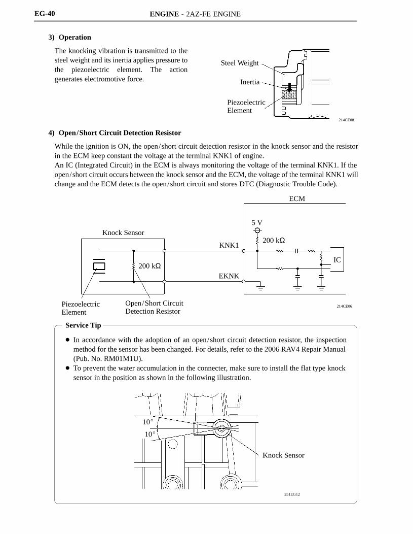
Service Tip
In accordance with the adoption of an open/short circuit detection resistor, the inspectionmethod for the sensor has been changed. For details, refer to the 2006 RAV4 Repair Manual(Pub. No. RM01M1U).
To prevent the water accumulation in the connecter, make sure to install the flat type knocksensor in the position as shown in the following illustration.
251EG12
10
10
Knock Sensor
EG-40
3) Operation
The knocking vibration is transmitted to thesteel weight and its inertia applies pressure tothe piezoelectric element. The actiongenerates electromotive force.
4) Open/Short Circuit Detection Resistor
While the ignition is ON, the open/short circuit detection resistor in the knock sensor and the resistorin the ECM keep constant the voltage at the terminal KNK1 of engine.An IC (Integrated Circuit) in the ECM is always monitoring the voltage of the terminal KNK1. If theopen/short circuit occurs between the knock sensor and the ECM, the voltage of the terminal KNK1 willchange and the ECM detects the open/short circuit and stores DTC (Diagnostic Trouble Code).

ENGINE - 2AZ-FE ENGINE
01NEG43Y
238EG79230LX12
Throttle Body
Throttle PositionSensor Portion
Throttle ControlMotor
MagneticYoke
Hall IC
Cross Section
Throttle PositionSensor
Magnetic Yoke
HallIC
HallIC
VTA1
ETA
VCTA
VTA2
ECMOutputVoltage
(V)5
0
Fully Close
10 90 ()
Fully Open
VTA2
VTA1
Throttle Valve Opening Angle
Service Tip
The inspection method differs from the conventional contact type throttle position sensor becausethis non-contact type sensor uses a Hall IC.For details, refer to the 2006 RAV4 Repair Manual (Pub. No. RM01M1U).
EG-41
Throttle Position Sensor
The throttle position sensor is mounted on the throttle body to detect the opening angle of the throttle valve.The throttle position sensor converts the magnetic flux density that changes when the magnetic yoke(located on the same axis as the throttle shaft) rotates around the Hall IC into electric signals to operate thethrottle control motor.

ENGINE - 2AZ-FE ENGINE
00SEG39Y
228TU25228TU24
A
A
Internal Construction
A - A Cross Section
AcceleratorPedal Arm
Hall IC
Magnetic Yoke
Accelerator PedalPosition Sensor
Magnetic Yoke
HallIC
HallIC
VPA
EPA
VCPAVPA2
EPA2
ECM OutputVoltage
(V)
5
0
VPA2
VPA
Fully Close Fully Open
90
Accelerator Pedal Depressed Angle
VCP2
Service Tip
The inspection method differs from the conventional contact type accelerator pedal position sensorbecause this non-contact type sensor uses a Hall IC.For details, refer to the 2006 RAV4 Repair Manual (Pab. No. RM01M0U).
EG-42
Accelerator Pedal Position Sensor
The non-contact type accelerator pedal position sensor uses a Hall IC.
The magnetic yoke that is mounted at the accelerator pedal arm rotates around the Hall IC in accordancewith the amount of effort that is applied to the accelerator pedal. The Hall IC converts the changes in themagnetic flux at that time into electrical signals, and outputs them as accelerator pedal effort to the ECM.
The Hall IC contains circuits for the main and sub signals. It converts the accelerator pedal depressedangles into electric signals with two differing characteristics and outputs them to the ECM.

ENGINE - 2AZ-FE ENGINE
00REG17Y
Accelerator PedalPosition Sensor
Throttle Valve
Throttle Position Sensor
ThrottleControlMotor
Mass AirFlow Meter
ECMSkidControlECU
IgnitionCoil
FuelInjector
: CAN
EG-43
6. ETCS-i (Electronic Throttle Control System-intelligent)
General
The ETCS-i is used, providing excellent throttle control in all the operating ranges. In the 2AZ-FEengine, the accelerator cable has been discontinued, and an accelerator pedal position sensor has beenprovided on the accelerator pedal.
In the conventional throttle body, the throttle valve opening is determined by the amount of theaccelerator pedal effort. In contrast, the ETCS-i uses the ECM to calculate the optimal throttle valveopening that is appropriate for the respective driving condition and uses a throttle control motor to controlthe opening.
The ETCS-i controls the IAC (Idle Air Control) system, the TRAC (Traction Control), VSC (VehicleStability Control) system and curise control system.
In case of an abnormal condition, this system switches to the limp mode.
System Diagram

ENGINE - 2AZ-FE ENGINE
Throttle Body
Throttle PositionSensor Portion
ReductionGears
Throttle Valve
Magnetic Yoke
Hall IC
Throttle ControlMotor
A
View from A
Cross Section 01NEG44Y
EG-44
Construction
1) Throttle Position Sensor
The throttle position sensor is mounted on the throttle body, to detect the opening angle of the throttlevalve.
2) Throttle Control Motor
A DC motor with excellent response and minimal power consumption is used for the throttle controlmotor. The ECM performs the duty ratio control of the direction and the amperage of the current thatflows to the throttle control motor in order to regulate the opening of the throttle valve.
Operation
1) General
The ECM drives the throttle control motor by determining the target throttle valve opening in accordancewith the respective operating condition.
Non-linear Control
Idle Air Control
TRAC Throttle Control
VSC Coordination Control
Cruise Control
ENGINE - 2AZ-FE ENGINE
005EG13Y
: With Control: Without Control
Vehicle’sLongitudinal G
Throttle ValveOpening Angle
Accelerator PedalDepressed Angle
0
0
0 Time
EG-45
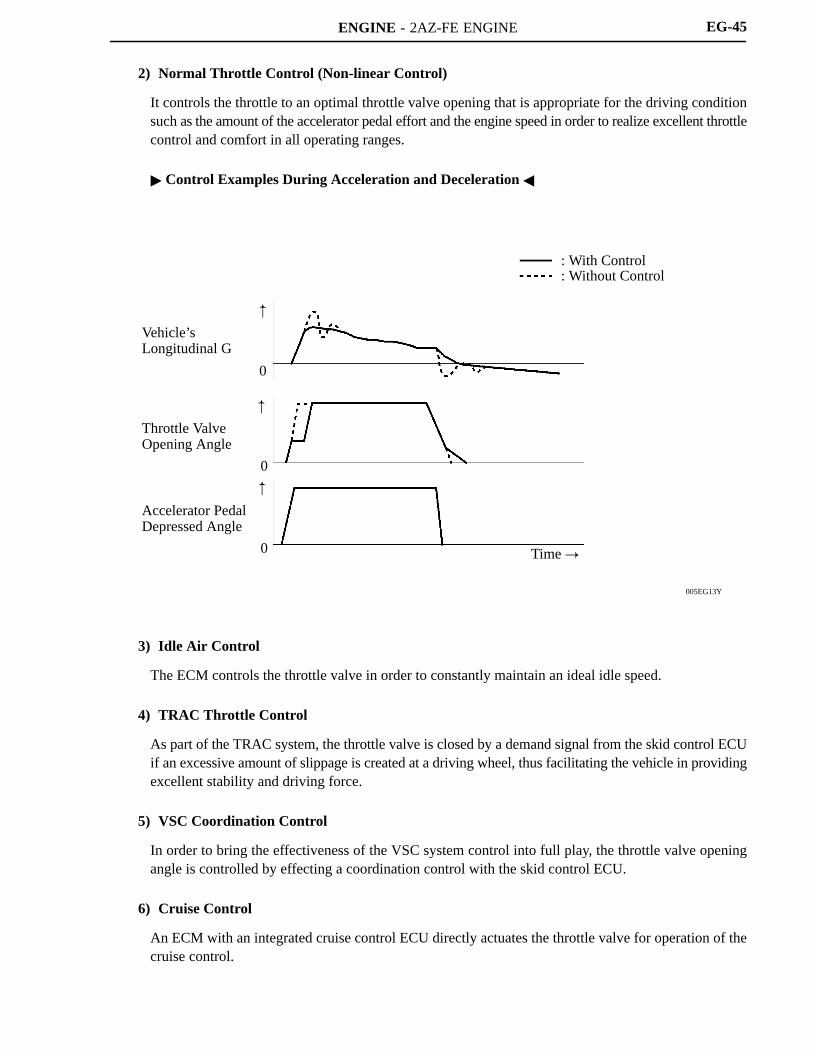
2) Normal Throttle Control (Non-linear Control)
It controls the throttle to an optimal throttle valve opening that is appropriate for the driving conditionsuch as the amount of the accelerator pedal effort and the engine speed in order to realize excellent throttlecontrol and comfort in all operating ranges.
Control Examples During Acceleration and Deceleration
3) Idle Air Control
The ECM controls the throttle valve in order to constantly maintain an ideal idle speed.
4) TRAC Throttle Control
As part of the TRAC system, the throttle valve is closed by a demand signal from the skid control ECUif an excessive amount of slippage is created at a driving wheel, thus facilitating the vehicle in providingexcellent stability and driving force.
5) VSC Coordination Control
In order to bring the effectiveness of the VSC system control into full play, the throttle valve openingangle is controlled by effecting a coordination control with the skid control ECU.
6) Cruise Control
An ECM with an integrated cruise control ECU directly actuates the throttle valve for operation of thecruise control.

ENGINE - 2AZ-FE ENGINE
199EG45
ECM
Accelerator PedalPosition Sensor
Main
Sub MainSub
ThrottlePositionSensor
Open
Throttle Valve ReturnSpring
ThrottleControlMotor
Accelerator Pedal Throttle Body
199EG46
Accelerator Pedal Throttle Body
ECM
Accelerator PedalPosition Sensor
MainSub
Close byReturn Spring
MainSub
ThrottlePositionSensor
Throttle Valve ReturnSpring
ThrottleControlMotor
EG-46
Fail-safe of Accelerator Pedal Position Sensor
The accelerator pedal position sensor is comprised of two (main, sub) sensor circuits. If a malfunctionoccurs in either one of the sensor circuits, the ECM detects the abnormal signal voltage differencebetween these two sensor circuits and switches to the limp mode. In the limp mode, the remaining circuitis used to calculate the accelerator pedal depressed angle, in order to operate the vehicle under the limpmode control.
If both circuits have malfunctions, the ECM detects the abnormal signal voltage from these two sensorcircuits and stops the throttle control. At this time, the vehicle can be driven within its idling range.

ENGINE - 2AZ-FE ENGINE
199EG47
Injectors ECM Ignition Coils
Accelerator PedalPosition Sensor
MainSub Main
Sub
Return toPrescribed Angle
Throttle ValveReturnSpring
ThrottleControlMotor
Accelerator Pedal Throttle Body
EG-47
Fail-safe of Throttle Position Sensor
The throttle position sensor is comprised of two (main, sub) sensor circuits. If a malfunction occurs ineither one or both of the sensor circuits, the ECM detects the abnormal signal voltage difference betweenthese two sensor circuits, cuts off the current to the throttle control motor, and switches to the limp mode.Then, the force of the return spring causes the throttle valve to return and stay at the prescribed openingangle. At this time, the vehicle can be driven in the limp mode while the engine output is regulatedthrough the control of the fuel injection (intermittent fuel-cut) and ignition timing in accordance with theaccelerator opening.
The same control as above is effected if the ECM detects a malfunction in the throttle control motorsystem.

ENGINE - 2AZ-FE ENGINE
DR011EG25
Camshaft Position Sensor
Engine CoolantTemperature Sensor
CrankshaftPosition Sensor
Camshaft TimingOil Control Valve
Throttle PositionSensor
ECM
Mass Air Flow Meter Vehicle Speed Signal
221EG16
Crankshaft Position Sensor
Mass Air Flow Meter
Throttle Position Sensor
Engine Coolant Temp. Sensor
Camshaft Position Sensor
Vehicle Speed Signal
ECM
Target Valve Timing
Feedback
Correction
Actual Valve Timing
Duty-cycleControl
Camshaft TimingOil Control Valve
EG-48
7. VVT-i (Variable Valve Timing-intelligent) System
General
The VVT-i system is designed to control the intake camshaft within a range of 40 (of Crankshaft Angle)to provide valve timing that is optimally suited to the engine condition. This realizes proper torque inall the speed ranges as well as realizing excellent fuel economy, and reducing exhaust emissions.
Using the engine speed signal, vehicle speed signal, and the signals from mass air flow meter, throttleposition sensor and engine coolant temperature sensor, the ECM can calculate optimal valve timing foreach driving condition and controls the camshaft timing oil control valve. In addition, the ECM usessignals from the camshaft position sensor and crankshaft position sensor to detect the actual valve timing,thus providing feedback control to achieve the target valve timing.

ENGINE - 2AZ-FE ENGINE
185EG48
185EG49
185EG50
287EG34
185EG48
185EG48
TDCLatest Timing
EX IN
BDCTo Advance Side
EX IN
EX IN
To Advance Side
EX IN
To Retard Side
Latest Timing
EX IN
Latest Timing
EX IN
EG-49
Effectiveness of the VVT-i System
Operation State Objective Effect
During Idling At Light Load
Minimizing overlap toreduce blowback to theintake side
Stabilized idling rpm Better fuel economy
At Medium LoadIncreasing overlapincreases internal EGR,reducing pumping loss
Better fuel economy Improved emission
control
In Low to MediumSpeed Range withHeavy Load
Advancing the intakevalve close timing forvolumetric efficiencyimprovement
Improved torque in lowto medium speed range
In High Speed Rangewith Heavy Load
Retarding the intakevalve close timing forvolumetric efficiencyimprovement
Improved output
At LowTemperature
Minimizing overlap toprevent blowback tothe intake side leads tothe lean burningcondition, andstabilizes the idlingspeed at fast idle
Stabilized fastidle rpm
Better fuel economy
Upon Starting Stopping the
Engine
Minimizing overlap tominimize blowback tothe intake side
Improved startability

ENGINE - 2AZ-FE ENGINE
169EG36
HousingLock Pin
Intake Camshaft
Vane (Fixed on Intake Camshaft)
Oil Pressure
At a Stop In Operation
Lock Pin
221EG17
To VVT-i Controller(Advance Side)
To VVT-i Controller(Retard Side)
Sleeve
Spring
DrainOil Pressure
DrainSpool Valve
CoilPlunger
EG-50
Construction
1) VVT-i Controller
This controller consists of the housing driven by the timing chain and the vane fixed on the intakecamshaft.The oil pressure sent from the advance or retard side path at the intake camshaft causes rotation in theVVT-i controller vane circumferential direction to vary the intake valve timing continuously.When the engine is stopped, the intake camshaft will be in the most retarded state to ensure startability.When hydraulic pressure is not applied to the VVT-i controller immediately after the engine has beenstarted, the lock pin locks the movement of the VVT-i controller to prevent a knocking noise.
2) Camshaft Timing Oil Control Valve
This camshaft timing oil control valve controls the spool valve position in accordance with the duty-cyclecontrol from the ECM. This allows hydraulic pressure to be applied to the VVT-i controller advance orretard sides. When the engine is stopped, the camshaft timing oil control valve is in the most retardedstate.

ENGINE - 2AZ-FE ENGINE
198EG35
Vane
Rotation Direction
Oil Pressure
ECM
IN Drain
198EG36
Vane
Rotation Direction
Oil Pressure
Drain IN
ECM
EG-51
Operation
1) Advance
When the camshaft timing oil control valve is operated as illustrated below by the advance signals fromthe ECM, the resultant oil pressure is applied to the advance side vane chamber to rotate the camshaftin the advance direction.
2) Retard
When the camshaft timing oil control valve is operated as illustrated below by the retard signals fromthe ECM, the resultant oil pressure is applied to the retard side vane chamber to rotate the camshaft inthe retard direction.
3) Hold
After reaching the target timing, the valve timing is held by keeping the camshaft timing oil control valvein the neutral position unless the traveling state changes.This adjusts the valve timing at the desired target position and prevents the engine oil from running outwhen it is unnecessary.

ENGINE - 2AZ-FE ENGINE
01NEG09Y
01NEG10Y
AirConditioningECU
Engine CoolantTemperature Sensor
FANL
ECM
FANH
Cooling FanRelay No.3
Cooling FanMotor No.2
Cooling FanRelay No.1
Cooling FanMotor No.1
Low Speed (Series Connection)
High Speed (Parallel Connection)
AirConditioningECU
Engine CoolantTemperature Sensor
FANL
ECM
FANH
Cooling FanRelay No.3
Cooling FanMotor No.2
Cooling FanRelay No.1
Cooling FanRelay No.2
Cooling FanMotor No.1: CAN
Cooling FanRelay No.2
EG-52
8. Cooling Fan Control
On the models with air conditioning, the ECM controls the operation of the cooling fan in two speeds (Lowand High) based on the engine coolant temperature sensor signal and the air conditioning ECU signal. Thiscontrol is accomplished by operating the 2 fan motors in 2 stages through low speed (series connection) andhigh speed (parallel connection).
Wiring Diagram
Cooling Fan Operation
Air Conditioning Condition Engine Coolant Temperature C (F)
A/C Compressor Refrigerant Pressure 94 (201.2) or lower 95.5 (203.9) or higher
OFF 1.2 MPa (12.5 kgf /cm2, 178 psi) or lower OFF High
ON1.2 MPa (12.5 kgf /cm2, 178 psi) or lower Low High
ON1.2 MPa (12.5 kgf /cm2, 178 psi) or higher High High

ENGINE - 2AZ-FE ENGINE
00REG18Y
Front AirbagSensor(RH and LH)
Curtain ShieldAirbag Sensor*(RH and LH)
AirbagSensor
Side AirbagSensor*(RH or LH)
ECM
CircuitOpeningRelay
FuelPumpMotor
: CAN
EG-53
9. Fuel Pump Control
A fuel cut control is used to stop the fuel pump when the SRS airbag is deployed at the front collision. In thissystem, the airbag deployment signal from the airbag sensor is detected by the ECM, which turns OFF thecircuit opening relay.After the fuel cut control has been activated, turning the ignition switch from OFF to ON cancels the fuel cutcontrol, and the engine can be restarted.
*: Models with SRS Driver, Front Passenger, Side and Curtain Shield Airbags

ENGINE - 2AZ-FE ENGINE
Service Tip
The canister pump module performs the EVAP leak check. This check is done approximately fivehours after the engine is turned off. So you may hear sound coming from underneath the luggagecompartment for several minutes. It does not indicate a malfunction.
The pinpoint pressure test procedure is carried out by pressurizing the fresh air line that runs fromthe pump module to the air filler neck. For details, refer to the 2006 RAV4 Repair Manual (Pub.No. RM01M1U).
EG-54
10. EVAP (evaporative Emission) Control System
General
The EVAP (evaporative emission) control system prevents the vapor gas that is created in the fuel tank frombeing released directly into the atmosphere.
The canister stores the vapor gas that has been created in the fuel tank.
The ECM controls the purge VSV in accordance with the driving conditions in order to direct the vaporgas into the engine, where it is burned.
In this system, the ECM checks the evaporative emission leak and outputs DTC (Diagnostic TroubleCode) in the event of a malfunction. An EVAP (evaporative emission) leak check consists of anapplication of a vacuum pressure to the system and monitoring the changes in the system pressure in orderto detect a leakage.
This system consists of the purge VSV, canister, refueling valve, canister pump module, and ECM.
The ORVR (Onboard Refueling Vapor Recovery) function is provided in the refueling valve.
The canister pressure sensor has been included to the canister pump module.
The canister filter has been provided on the fresh air line. This canister filter is maintenance-free.
The followings are the typical conditions for enabling an EVAP leak check:
Typical EnablingCondition
Five hours have elapsed after the engine has been turned OFF*. Altitude: Below 2400 m (8000 feet) Battery voltage: 10.5 V or more Ignition switch: OFF Engine coolant temperature: 4.4 to 35C (40 to 95F) Intake air temperature: 4.4 to 35C (40 to 95F)
*: If engine coolant temperature does not drop below 35C (95F), this time should be extended to 7hours.Even after that, if the temperature is not less than 35C (95F), the time should be extended to 9.5 hours.

ENGINE - 2AZ-FE ENGINE
00REG22Y
To Intake Manifold
Purge VSV
Purge AirLine
ECM
Fuel Tank
Canister Filter
Fresh Air Line
Refueling Valve
Canister Pump Module
VentValve
Leak Detection Pump& Pump Motor
CanisterPressure Sensor
CanisterP
M
EG-55
System Diagram
Function of Main Components
Component Function
Canister Contains activated charcoal to absorb the vapor gas that is created in thefuel tank.
Refueling
Controls the flow rate of the vapor gas from the fuel tank to the canisterwhen the system is purging or during refueling.Refueling
ValveRestrictor Passage Prevents a large amount of vacuum during purge operation or system
monitoring operation from affecting the pressure in the fuel tank.
Fresh Air Line Fresh air goes into the canister and the cleaned drain air goes out intothe atmosphere.
Vent Valve Opens and closes the fresh air line in accordance with the signals fromthe ECM.
CanisterPump Module
Leak DetectionPump
Applies vacuum pressure to the EVAP control system in accordancewith the signals from the ECM.p
CanisterPressure Sensor
Detects the pressure in the EVAP control system and sends the signalsto the ECM.
Purge VSV
Opens in accordance with the signals from the ECM when the systemis purging, in order to send the vapor gas that was absorbed by thecanister into the intake manifold. In system monitoring mode, this valvecontrols the introduction of the vacuum into the fuel tank.
Canister Filter Prevents dust and debris in the fresh air from entering the system.
ECM
Controls the canister pump module and purge VSV in accordance withthe signals from various sensors, in order to achieve a purge volume thatsuits the driving conditions. In addition, the ECM monitors the systemfor any leakage and outputs a DTC if a malfunction is found.
ENGINE - 2AZ-FE ENGINE
D13N07285EG76
Chamber AFresh Air Line
RefuelingValve (Open)
Chamber B
From FuelTank
Internal Pressure
CanisterTo FuelTank
Positive Pressure(Fuel Tank Pressure)
Restrictor PassageNegative Pressure(Intake Manifold Pressure)
During Refueling During Purge Operation orSystem Monitoring Operation
228TU119
Fuel Tank Cap Fresh Air
Fuel Inlet Pipe
To Canister
Cleaned Drain Air
EG-56
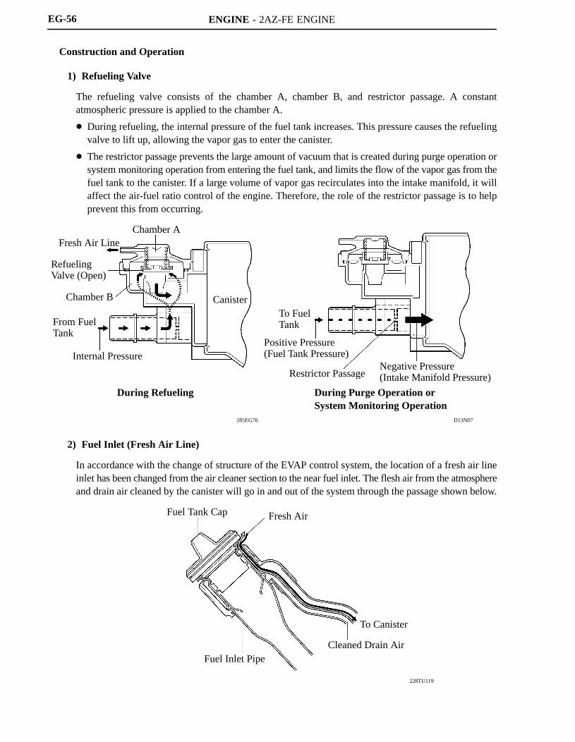
Construction and Operation
1) Refueling Valve
The refueling valve consists of the chamber A, chamber B, and restrictor passage. A constantatmospheric pressure is applied to the chamber A.
During refueling, the internal pressure of the fuel tank increases. This pressure causes the refuelingvalve to lift up, allowing the vapor gas to enter the canister.
The restrictor passage prevents the large amount of vacuum that is created during purge operation orsystem monitoring operation from entering the fuel tank, and limits the flow of the vapor gas from thefuel tank to the canister. If a large volume of vapor gas recirculates into the intake manifold, it willaffect the air-fuel ratio control of the engine. Therefore, the role of the restrictor passage is to helpprevent this from occurring.
2) Fuel Inlet (Fresh Air Line)
In accordance with the change of structure of the EVAP control system, the location of a fresh air lineinlet has been changed from the air cleaner section to the near fuel inlet. The flesh air from the atmosphereand drain air cleaned by the canister will go in and out of the system through the passage shown below.

ENGINE - 2AZ-FE ENGINE
279EG26
D13N17
279EG25
Fresh Air
CanisterPressure Sensor
Leak Detection Pump
Pump Motor Vane Pump
CanisterPressure Sensor
Vent Valve
Fresh Air
Canister
Canister Pump Module
Fresh Air
Vent Valve
Filter
Filter
MLeak Detection Pump& Pump Motor
CanisterPressure Sensor
P
Reference Orifice[0.5 mm (0.02 in.) Diameter]
Filter
To Canister
EG-57
3) Canister Pump Module
Canister pump module consists of the vent valve, leak detection pump, and canister pressure sensor.
The vent valve switches the passages in accordance with the signals received from the ECM.
A DC type brushless motor is used for the pump motor.
A vane type vacuum pump is used.
Simple Diagram
ENGINE - 2AZ-FE ENGINE
00REG23Y
To Intake Manifold
Atmosphere
Purge VSV(Open)
ECM
00REG24Y
Close
Open
EG-58
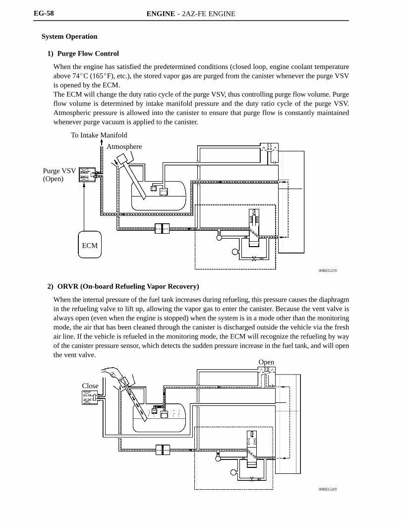
System Operation
1) Purge Flow Control
When the engine has satisfied the predetermined conditions (closed loop, engine coolant temperatureabove 74C (165F), etc.), the stored vapor gas are purged from the canister whenever the purge VSVis opened by the ECM.The ECM will change the duty ratio cycle of the purge VSV, thus controlling purge flow volume. Purgeflow volume is determined by intake manifold pressure and the duty ratio cycle of the purge VSV.Atmospheric pressure is allowed into the canister to ensure that purge flow is constantly maintainedwhenever purge vacuum is applied to the canister.
2) ORVR (On-board Refueling Vapor Recovery)
When the internal pressure of the fuel tank increases during refueling, this pressure causes the diaphragmin the refueling valve to lift up, allowing the vapor gas to enter the canister. Because the vent valve isalways open (even when the engine is stopped) when the system is in a mode other than the monitoringmode, the air that has been cleaned through the canister is discharged outside the vehicle via the freshair line. If the vehicle is refueled in the monitoring mode, the ECM will recognize the refueling by wayof the canister pressure sensor, which detects the sudden pressure increase in the fuel tank, and will openthe vent valve.

ENGINE - 2AZ-FE ENGINE
275TU47
PurgeVSV
VentValve
Pump Motor
SystemPressure
ON (Open)OFF (Close)
ON
OFF (Vent)
ON
OFF
Atmospheric Pressure
0.02 in. Leak Pressure
1) 2) 3) 4) 5) 6)
EG-59
3) EVAP Leak Check
a. General
The EVAP leak check operates in accordance with the following timing chart:
Timing Chart
Order Operation Description Time
1)Atmospheric PressureMeasurement
ECM turns vent valve OFF (vent) and measures EVAPcontrol system pressure to memorize atmospheric pressure.
10 sec.
2)0.02 in. LeakPressure Measurement
Leak detection pump creates negative pressure (vacuum)through 0.02 in. orifice and the pressure is measured. ECMdetermines this as 0.02 in. leak pressure.
60 sec.
3) EVAP Leak Check
Leak detection pump creates negative pressure (vacuum) inEVAP control system and EVAP control system pressure ismeasured. If stabilized pressure is larger than 0.02 in. leakpressure, ECM determines EVAP control system has aleakage.If EVAP control system pressure does not stabilize within 12minutes, ECM cancels EVAP monitor.
Within12 min.
4) Purge VSV MonitorECM opens purge VSV and measures EVAP control systempressure increase. If increase is large, ECM interprets this asnormal.
10 sec.
5)Repeat 0.02 in. LeakPressure Measurement
Leak detection pump creates negative pressure (vacuum)through 0.02 in. orifice and pressure is measured. ECMdetermines this as 0.02 in. leak pressure.
60 sec.
6) Final CheckECM measures atmospheric pressure and records monitorresult.
—
ENGINE - 2AZ-FE ENGINE
00REG25Y
D13N22
Atmosphere
Purge VSV(OFF)
ECM
Canister Pump Module
Vent Valve(OFF)
Leak Detection Pump& Pump Motor
CanisterPressure Sensor
Purge VSV
Vent Valve
Pump Motor
System Pressure
ON (Open)
OFF (Close)
ONOFF (Vent)
ONOFF
Atmospheric Pressure
0.02 in. Leak Pressure
Atmospheric Pressure Measurement
P
M
EG-60
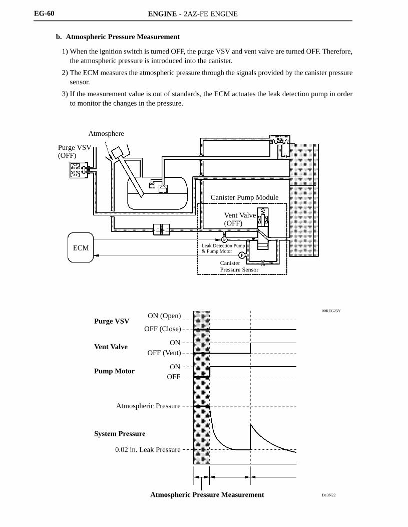
b. Atmospheric Pressure Measurement
1) When the ignition switch is turned OFF, the purge VSV and vent valve are turned OFF. Therefore,the atmospheric pressure is introduced into the canister.
2) The ECM measures the atmospheric pressure through the signals provided by the canister pressuresensor.
3) If the measurement value is out of standards, the ECM actuates the leak detection pump in orderto monitor the changes in the pressure.
ENGINE - 2AZ-FE ENGINE
00REG26Y
275TU48
Atmosphere
Purge VSV(OFF)
ECM
Canister Pump Module
Vent Valve(OFF)
Leak Detection Pump& Pump Motor
Canister PressureSensor
Reference Orifice
Purge VSV
Vent Valve
Pump Motor
System Pressure
ON (Open)OFF (Close)
ON
OFF (Vent)
ON
OFF
Atmospheric Pressure
0.02 in. Leak Pressure
0.02 in. Leak Pressure Measurement
M
P
EG-61
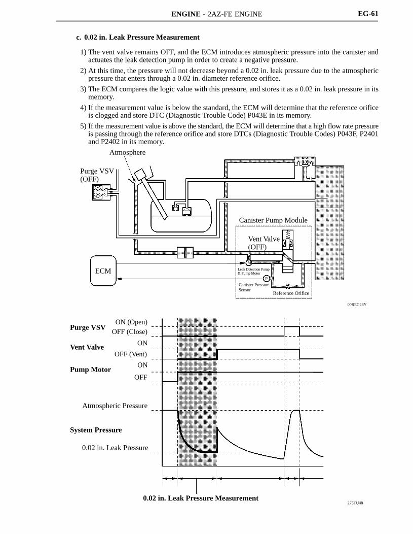
c. 0.02 in. Leak Pressure Measurement
1) The vent valve remains OFF, and the ECM introduces atmospheric pressure into the canister andactuates the leak detection pump in order to create a negative pressure.
2) At this time, the pressure will not decrease beyond a 0.02 in. leak pressure due to the atmosphericpressure that enters through a 0.02 in. diameter reference orifice.
3) The ECM compares the logic value with this pressure, and stores it as a 0.02 in. leak pressure in itsmemory.
4) If the measurement value is below the standard, the ECM will determine that the reference orificeis clogged and store DTC (Diagnostic Trouble Code) P043E in its memory.
5) If the measurement value is above the standard, the ECM will determine that a high flow rate pressureis passing through the reference orifice and store DTCs (Diagnostic Trouble Codes) P043F, P2401and P2402 in its memory.

ENGINE - 2AZ-FE ENGINE
00REG27Y
275TU49
Purge VSV(OFF)
Atmosphere
ECM
Canister Pump Module
Vent Valve(ON)
Leak Detection Pump& Pump Motor
CanisterPressure Sensor
M
P
Reference Orifice
Vacuum
Purge VSV
Vent Valve
Pump Motor
System Pressure
OFF (Close)ON (Open)
ON
OFF (Vent)
ON
OFF
Atmospheric Pressure
0.02 in. Leak Pressure
EVAP Leak Check
P0455
P0456
Normal
EG-62
d. EVAP Leak Check
1) While actuating the leak detection pump, the ECM turns ON the vent valve in order to introduce avacuum into the canister.
2) When the pressure in the system stabilizes, the ECM compares this pressure with the 0.02 in. leakpressure in order to check for a leakage.
3) If the measurement value is below the 0.02 in. leak pressure, the ECM determines that there is noleakage.
4) If the measurement value is above the 0.02 in. leak pressure and near atmospheric pressure, the ECMdetermines that there is a gross leakage (large hole) and stores DTC P0455 in its memory.
5) If the measurement value is above the 0.02 in. leak pressure, the ECM determines that there is a smallleakage and stores DTC P0456 in its memory.
ENGINE - 2AZ-FE ENGINE
00REG28Y
275TU50
M
P
Atmosphere
Atmosphere
Purge VSV(ON)
ECM
Canister Pump Module
Vent Valve(ON)
Leak Detection Pump& Pump Motor
CanisterPressure Sensor
Purge VSV Monitor
P0441
Normal
Purge VSV
Vent Valve
Pump Motor
System Pressure
ON (Open)
OFF (Close)
ON
OFF (Vent)
ON
OFF
Atmospheric Pressure
0.02 in. Leak Pressure
EG-63
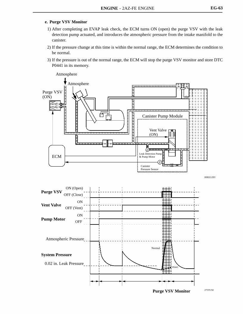
e. Purge VSV Monitor
1) After completing an EVAP leak check, the ECM turns ON (open) the purge VSV with the leakdetection pump actuated, and introduces the atmospheric pressure from the intake manifold to thecanister.
2) If the pressure change at this time is within the normal range, the ECM determines the condition tobe normal.
3) If the pressure is out of the normal range, the ECM will stop the purge VSV monitor and store DTCP0441 in its memory.
ENGINE - 2AZ-FE ENGINE
01MEG03Y
275TU51
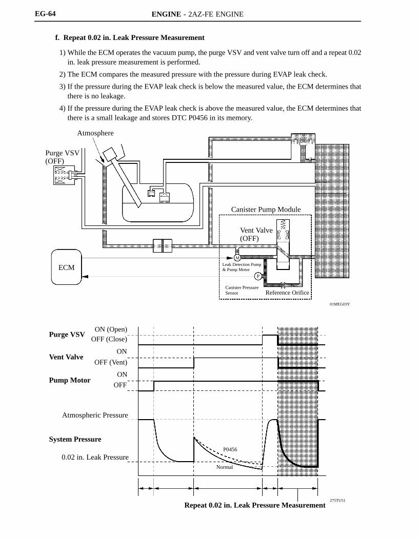
Repeat 0.02 in. Leak Pressure Measurement
Atmosphere
Purge VSV(OFF)
ECM
Canister Pump Module
Vent Valve(OFF)
Leak Detection Pump& Pump Motor
Canister PressureSensor Reference Orifice
Purge VSV
Vent Valve
Pump Motor
System Pressure
ON (Open)OFF (Close)
ON
OFF (Vent)
ON
OFF
Atmospheric Pressure
0.02 in. Leak PressureP0456
Normal
M
P
EG-64
f. Repeat 0.02 in. Leak Pressure Measurement
1) While the ECM operates the vacuum pump, the purge VSV and vent valve turn off and a repeat 0.02in. leak pressure measurement is performed.
2) The ECM compares the measured pressure with the pressure during EVAP leak check.
3) If the pressure during the EVAP leak check is below the measured value, the ECM determines thatthere is no leakage.
4) If the pressure during the EVAP leak check is above the measured value, the ECM determines thatthere is a small leakage and stores DTC P0456 in its memory.
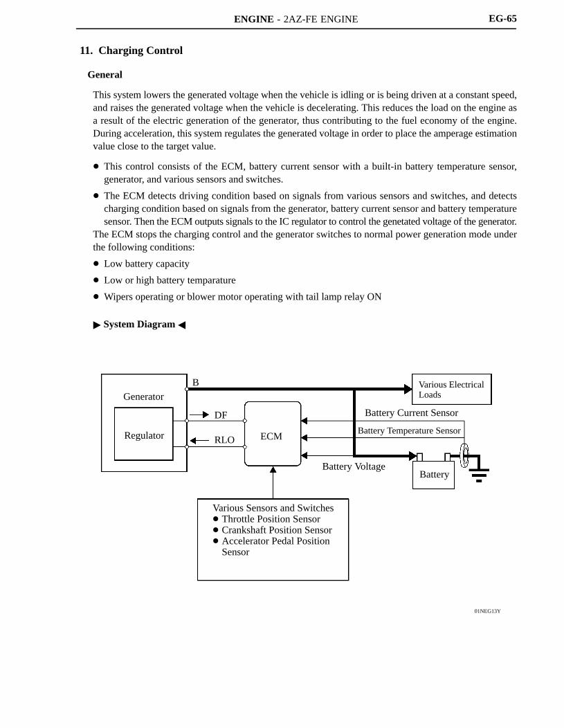
ENGINE - 2AZ-FE ENGINE
01NEG13Y
Generator
Regulator
B
DF
RLO ECM
Various ElectricalLoads
Battery Current Sensor
Battery Temperature Sensor
Battery VoltageBattery
Various Sensors and Switches Throttle Position Sensor Crankshaft Position Sensor Accelerator Pedal Position
Sensor
EG-65
11. Charging Control
General
This system lowers the generated voltage when the vehicle is idling or is being driven at a constant speed,and raises the generated voltage when the vehicle is decelerating. This reduces the load on the engine asa result of the electric generation of the generator, thus contributing to the fuel economy of the engine.During acceleration, this system regulates the generated voltage in order to place the amperage estimationvalue close to the target value.
This control consists of the ECM, battery current sensor with a built-in battery temperature sensor,generator, and various sensors and switches.
The ECM detects driving condition based on signals from various sensors and switches, and detectscharging condition based on signals from the generator, battery current sensor and battery temperaturesensor. Then the ECM outputs signals to the IC regulator to control the genetated voltage of the generator.
The ECM stops the charging control and the generator switches to normal power generation mode underthe following conditions:
Low battery capacity
Low or high battery temparature
Wipers operating or blower motor operating with tail lamp relay ON
System Diagram

ENGINE - 2AZ-FE ENGINE
258AS61281EG86
OutputVoltage
5 (V)
0- 100 Current +100 (A)
Characteristic of Current Sensor
288EG61C
(C)60Battery Temperature
0
Resistance
(kΩ)
6
EG-66
Battery Current Sensor
Installed on the negative terminal of the battery, this sensor detects the amount of charging and dischargingamperage of the battery and sends signal to the ECM. Based on this signal, the ECM calculates the batterycapacity. A Hall IC is used for detecting the amount of charging and discharging amperage. The changesthat occur in the magnetic flux density in the core as a result of the charging and amperage of the batteryare converted and output as voltage.
Batter Temperature Sensor
The battery temperature sensor is built into the battery current sensor.
The battery characteristic (battery internal resistance) of taking in current for charging varies accordingto battery electrolyte temperature. If the electrolyte temperature is too low or too high, the battery internalresistance will increase, resulting in early deterioration. To prevent this, the battery temperature sensorchanges its resistance as shown below to detect the temperature.
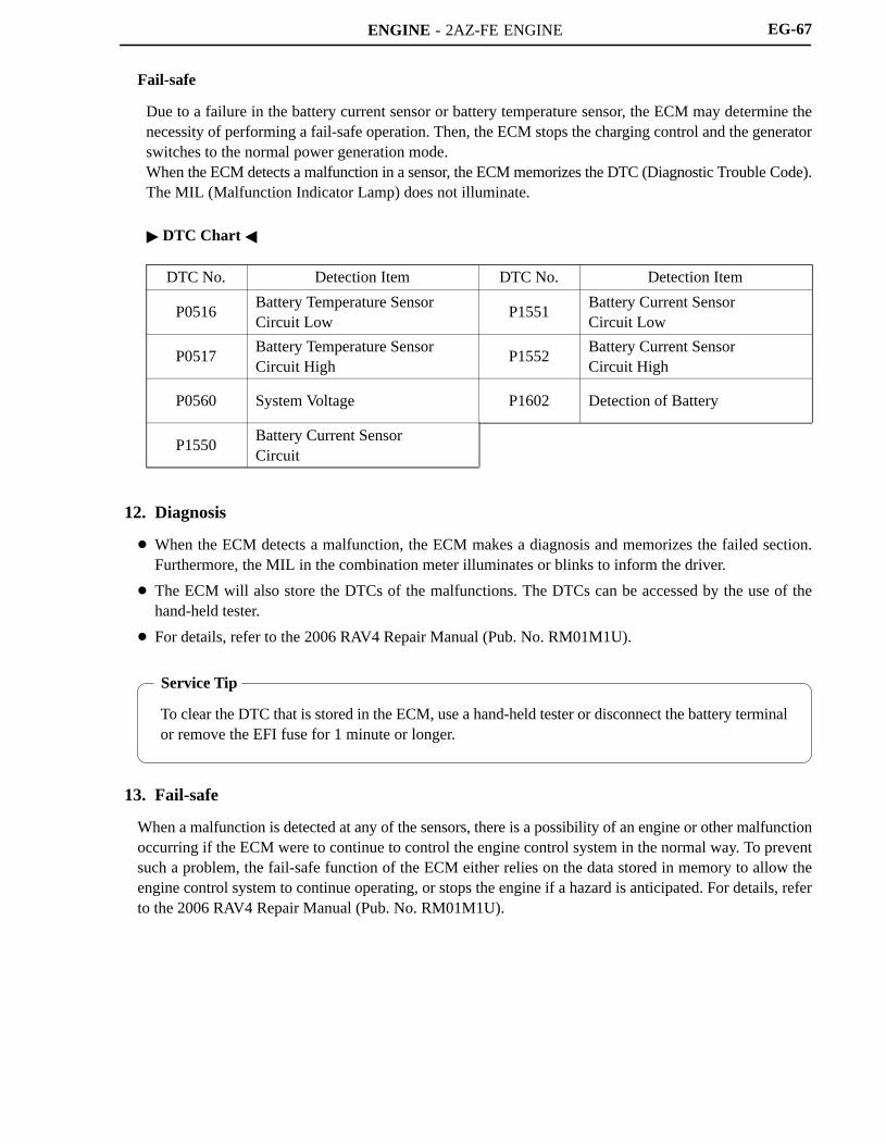
ENGINE - 2AZ-FE ENGINE
Service Tip
To clear the DTC that is stored in the ECM, use a hand-held tester or disconnect the battery terminalor remove the EFI fuse for 1 minute or longer.
EG-67
Fail-safe
Due to a failure in the battery current sensor or battery temperature sensor, the ECM may determine thenecessity of performing a fail-safe operation. Then, the ECM stops the charging control and the generatorswitches to the normal power generation mode.When the ECM detects a malfunction in a sensor, the ECM memorizes the DTC (Diagnostic Trouble Code).The MIL (Malfunction Indicator Lamp) does not illuminate.
DTC Chart
DTC No. Detection Item DTC No. Detection Item
P0516Battery Temperature SensorCircuit Low
P1551Battery Current SensorCircuit Low
P0517Battery Temperature SensorCircuit High
P1552Battery Current SensorCircuit High
P0560 System Voltage P1602 Detection of Battery
P1550Battery Current SensorCircuit
12. Diagnosis
When the ECM detects a malfunction, the ECM makes a diagnosis and memorizes the failed section.Furthermore, the MIL in the combination meter illuminates or blinks to inform the driver.
The ECM will also store the DTCs of the malfunctions. The DTCs can be accessed by the use of thehand-held tester.
For details, refer to the 2006 RAV4 Repair Manual (Pub. No. RM01M1U).
13. Fail-safe
When a malfunction is detected at any of the sensors, there is a possibility of an engine or other malfunctionoccurring if the ECM were to continue to control the engine control system in the normal way. To preventsuch a problem, the fail-safe function of the ECM either relies on the data stored in memory to allow theengine control system to continue operating, or stops the engine if a hazard is anticipated. For details, referto the 2006 RAV4 Repair Manual (Pub. No. RM01M1U).