pencil beam all-optical ultrasound imaging - ucl · pencil beam all-optical ultrasound imaging...
TRANSCRIPT
Pencil beam all-optical ultrasound imaging
ERWIN J. ALLES,1,* SACHA NOIMARK,1,2 EDWARD ZHANG,1 PAUL C.BEARD,1 AND ADRIEN E. DESJARDINS1
1Department of Medical Physics and Biomedical Engineering, University College London, London WC1E6BT, UK2Materials Chemistry Research Centre, UCL Department of Chemistry, London WC1H 0AJ, UK*[email protected]
Abstract: A miniature, directional fibre-optic acoustic source is presented that employsgeometrical focussing to generate a nearly-collimated acoustic pencil beam. When paired with afibre-optic acoustic detector, an all-optical ultrasound probe with an outer diameter of 2.5 mmis obtained that acquires a pulse-echo image line at each probe position without the need forimage reconstruction. B-mode images can be acquired by translating the probe and concatenatingthe image lines, and artefacts resulting from probe positioning uncertainty are shown to besignificantly lower than those observed for conventional synthetic aperture scanning of a non-directional acoustic source. The high image quality obtained for excised vascular tissue suggeststhat the all-optical ultrasound probe is ideally suited for in vivo, interventional applications.
Published by The Optical Society under the terms of the Creative Commons Attribution 4.0 License. Further distributionof this work must maintain attribution to the author(s) and the published article’s title, journal citation, and DOI.
OCIS codes: (170.7170) Ultrasound; (110.5125) Photoacoustics; (110.2350) Fiber optics imaging; (060.2380) Fiberoptics sources and detectors; (170.0110) Imaging systems.
References and links1. Y. Hou, J.-S. Kim, S.-W. Huang, S. Ashkenazi, L. J. Guo, and M. O’Donnell, “Characterization of a broadband all-
optical ultrasound transducer-from optical and acoustical properties to imaging,” IEEE Trans. Ultrason. FerroelectricsFreq. Contr. 55(8), 1867–1877 (2008).
2. Y. Hou, S. Ashkenazi, S.-W. Huang, and M. O’Donnell, “An integrated optoacoustic transducer combining etalonand black PDMS structures,” IEEE Trans. Ultrason. Ferroelectrics Freq. Contr. 55(12), 2719–2725 (2008).
3. E. Biagi, S. Cerbai, L. Masotti, L. Belsito, A. Roncaglia, G. Masetti, and N. Speciale, “Fiber optic broadbandultrasonic probe for virtual biopsy: Technological solutions,” J. Sensors 2010, 917314 (2010).
4. C. Sheaff and S. Ashkenazi, “An all-optical thin-film high-frequency ultrasound transducer,” in Proceedings of IEEEInternational Ultrasonics Symposium (IEEE, 2011), pp. 1944–1947.
5. B.-Y. Hsieh, S.-L. Chen, T. Ling, L.J. Guo, and P.-C. Li, “All-optical scanhead for ultrasound and photoacousticimaging - imaging mode switching by dichroic filtering,” Photoacoustics 2(1), 39–46 (2014).
6. C. Sheaff and S. Ashkenazi, “Polyimide-etalon all-optical ultrasound transducer for high frequency applications,”Proc. SPIE 8943, 894334M (2014).
7. R.J. Colchester, E.Z. Zhang, C.A. Mosse, P.C. Beard, I. Papakonstantinou, and A.E. Desjardins, “Broadband miniatureoptical ultrasound probe for high resolution vascular tissue imaging,” Biomed. Opt. Express 6(4), 1502–1511 (2015).
8. P.C. Beard, “Biomedical photoacoustic imaging,” Interface focus 1(4), 602–631 (2011).9. B. Cox, E. Zhang, J. Laufer, and P. Beard, “Fabry-Pérot polymer film fibre-optic hydrophones and arrays for ultrasound
field characterisation,” in Journal of Physics: Conference Series, volume 1 (IOP Publishing, 2004), pp. 32–37.10. E.Z. Zhang and P.C. Beard, “Characteristics of optimized fibre-optic ultrasound receivers for minimally invasive
photoacoustic detection,” Proc. SPIE 9323, 932311 (2015).11. S. Leinders, W. Westerveld, J. Pozo, P. van Neer, B. Snyder, P. O’Brien, H. Urbach, N. de Jong, and M. Verweij,
“A sensitive optical micro-machined ultrasound sensor (OMUS) based on a silicon photonic ring resonator on anacoustical membrane,” Sci. Rep. 5, 14328 (2015).
12. H.W. Baac, J.G. Ok, A. Maxwell, K.-T. Lee, Y.-C. Chen, A.J. Hart, Z. Xu, E. Yoon, and L.J. Guo, “Carbon-nanotubeoptoacoustic lens for focused ultrasound generation and high-precision targeted therapy,” Sci. Rep. 2, 989 (2012).
13. R.J. Colchester, C.A. Mosse, D.S. Bhachu, J.C. Bear, C.J. Carmalt, I.P. Parkin, B.E. Treeby, I. Papakonstantinou, andA.E. Desjardins, “Laser-generated ultrasound with optical fibres using functionalised carbon nanotube compositecoatings,” Appl. Phys. Lett. 104(17), 173502 (2014).
14. S. Noimark, R.J. Colchester, B.J. Blackburn, E.Z. Zhang, E.J. Alles, S. Ourselin, P.C. Beard, I. Papakonstantinou,I.P. Parkin, and A.E. Desjardins, “Carbon-nanotube-PDMS composite coatings on optical fibres for all-opticalultrasound imaging,” Appl. Funct. Mater. (to be published).
Vol. 7, No. 9 | 1 Sep 2016 | BIOMEDICAL OPTICS EXPRESS 3696
#268617 Journal © 2016
http://dx.doi.org/10.1364/BOE.7.003696 Received 27 Jun 2016; revised 8 Aug 2016; accepted 8 Aug 2016; published 26 Aug 2016

15. E. Zhang, J. Laufer, and P. Beard, “Backward-mode multiwavelength photoacoustic scanner using a planar Fabry-Pérotpolymer film ultrasound sensor for high-resolution three-dimensional imaging of biological tissues,” Appl. Opt.47(4), 561–577 (2008).
16. X. Zeng and R.J. McGough, “Optimal simulations of ultrasonic fields produced by large thermal therapy arrays usingthe angular spectrum approach,” J. Acoust. Soc. Am. 125(5), 2967–2977 (2009).
17. M. Karaman, P.-C. Li, and M. O’Donnell, “Synthetic aperture imaging for small scale systems,” IEEE Trans.Ultrason. Ferroelectrics Freq. Contr. 42(3), 429–442 (1995).
18. RJ McGough, “FOCUS: Fast Object-Oriented C++ Ultrasound Simulator,” http://www.egr.msu.edu/~fultras-web/.
19. J.T. Fokkema and P.M. van den Berg, Seismic Applications of Acoustic Reciprocity (Elsevier, 1993).20. B.J. Manning, K. Ivancev, and P.L. Harris, “In situ fenestration in the aortic arch,” J. Vasc. Surg. 52(2), 491–494
(2010).21. S.H. Contreras Ortiz, T. Chiu, and M.D. Fox, “Ultrasound image enhancement: A review,” Biomed. Signal Process.
Contr. 7(5), 419–428 (2012).22. H. Gomersall, D. Hodgson, R. Prager, N. Kingsbury, G. Treece, and A. Gee, “Efficient implementation of
spatially-varying 3-D ultrasound deconvolution,” IEEE Trans. Ultrason. Ferroelectrics Freq. Contr. 58(1), 234–238(2011).
23. F. Kral, E.J. Puschban, H. Riechelmann, and W. Freysinger, “Comparison of optical and electromagnetic tracking fornavigated lateral skull base surgery,” Int. J. Med. Robot. 9(2), 247–252 (2013).
24. E. Lugez, H. Sadjadi, D.R. Pichora, R.E. Ellis, S.G. Akl, and G. Fichtinger, “Electromagnetic tracking in surgicaland interventional environments: usability study,” Int. J. Comput. Assist. Radiol. Surg. 10(3), 253–262 (2015).
25. E.J. Alles, R.J. Colchester, and A.E. Desjardins, “Adaptive light modulation for improved resolution and efficiency inall-optical pulse-echo ultrasound,” IEEE Trans. Ultrason. Ferroelectrics Freq. Contr. 63(1), 83–90 (2016).
26. J.-y. Lu, T.K. Song, R.R. Kinnick, and J.F. Greenleaf, “In vitro and in vivo real-time imaging with ultrasonic limiteddiffraction beams,” IEEE Trans. Med. Imag. 12(4), 819–829 (1993).
27. A. Nikoozadeh, O. Oralkan, M. Gencel, J.W. Choe, D.N. Stephens, A. De La Rama, P. Chen, F. Lin, A. Dentinger, andD. Wildes, “Forward-looking intracardiac imaging catheters using fully integrated CMUT arrays,” in Proceedings ofIEEE International Ultrasonics Symposium (IEEE, 2010), pp. 770–773.
28. VisualSonics, “Vevo 770 System,” http://www.visualsonics.com/products/vevo-770.
1. Introduction
All-optical ultrasound imaging has recently been demonstrated to yield high-quality images thatcompare favourably to those obtained with conventional piezoelectric ultrasound probes [1–7].In all-optical ultrasound probes, ultrasound is generated photoacoustically through pulsed ormodulated illumination of an optically absorbing coating, where thermal deposition causes anincrease in pressure that propagates through the surrounding medium as an acoustic wave [8].Back-scattered acoustic waves are typically detected using Fabry-Pérot etalons [2, 3, 6, 9, 10] orring resonators [5, 11].An optical acoustic source fabricated on the tip of an optical fibre can generate ultrasound
with bandwidths and pressures comparable to or better than those generated by conventionalpiezoelectric transducers [12–14]. When paired with a fibre containing an optical acousticdetector, an all-optical acoustic probe is obtained that is readily miniaturised and inexpensive tofabricate. Such all-optical ultrasound probes, which typically comprise two optical fibres (oneeach for transmission and reception), are ideally suited to minimally invasive interventionalapplications where space is limited.
Images of ex vivo tissue have previously been acquired through precise motorised scanning ofan all-optical ultrasound probe across a synthetic aperture, whilst recording pulse-echo signals atuniform intervals [7]. Due to the low directionality of the acoustic source and the high sensitivityof the detector, the resulting images exhibit high resolution and low noise levels. However, theparadigm of mechanically scanning a synthetic aperture is unrealistic in an interventional setting,where micron-scale accuracy in probe position manipulation or tracking is currently not possible.As will be shown below, the resulting positioning uncertainty can introduce strong artefacts uponimage reconstruction.In this study, a different approach is presented where a highly directional optical acoustic
source is used to generate a nearly-collimated pencil beam. Only structures located within
Vol. 7, No. 9 | 1 Sep 2016 | BIOMEDICAL OPTICS EXPRESS 3697
the pencil beam are insonified and generate a pulse-echo response, and hence only a singlerecording is required to obtain an image line. As no image reconstruction is required to focus theacoustic energy, the positioning uncertainty image artefacts can be mitigated. The performanceof a non-directional and a directional probe are compared both in the absence and presence ofpositioning errors, and the image quality obtained with the directional probe is demonstrated onex vivo vascular tissue.
2. Methods
Two all-optical pulse-echo ultrasound imaging probes were developed. The first probe wasnon-directional, where ultrasound was generated at the distal end of a flat-cleaved optical fibre.The second probe achieved an acoustic pencil beam through directional ultrasound transmissionby a concave surface. With both probes, pulsed laser light with a duration of 2 ns and a wavelengthof 1064 nm (SPOT-10-500-1064, Elforlight, U.K.) was delivered to an optically absorbingcoating to generate ultrasound via the photoacoustic effect. To record the acoustic pulse-echosignals, a fibre-optic acoustic detector was used that comprised a Fabry-Pérot cavity at the distalend [10]. This detector was interrogated by measuring the detector’s reflectivity with a tunablelaser (TUNICS T100S-HP, Yenista, France) and a custom photodiode. The wavelength of theinterrogation laser was adjusted to correspond with the peak derivative of the detector’s cavitytransfer function [15]. Acoustic data were sampled using a high-speed data acquisition card(250 MSa/s, 14-bit; M4i.4420-x8, Spectrum, Germany). Acoustical cross-talk between the opticalsource and detector was suppressed using the method described in [7], and digital time gaincompensation was applied to compensate for geometrical attenuation.
2.1. Non-directional probe
In the non-directional probe, ultrasound was generated in an optically absorbing coating depositedon a step-index optical fibre (core/cladding diameter: 200/220 µm). This coating comprised athin (≤ 1 µm) layer of functionalised carbon nanotubes as optical absorbers and a 20 µm thicklayer of polydimethylsiloxane (PDMS) as an elastomeric host, and was dip-coated onto the distalend of the optical fibre [14].
2.2. Pencil beam probe
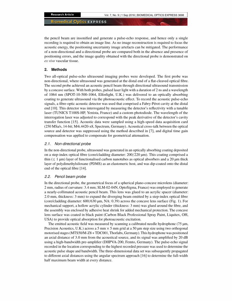
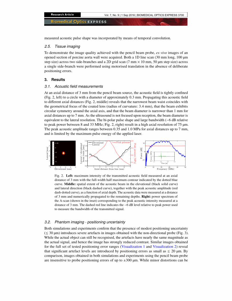
In the directional probe, the geometrical focus of a spherical plano-concave microlens (diameter:2 mm, radius of curvature: 3.4 mm; SLM-02-04N, OptoSigma, France) was employed to generatea nearly-collimated acoustic pencil beam. This lens was glued to an acrylic spacer (diameter:2.0 mm, thickness: 3 mm) to expand the diverging beam emitted by a step-index optical fibre(core/cladding diameter: 600/630 µm, NA: 0.39) across the concave lens surface (Fig. 1). Formechanical support, a hollow acrylic cylinder (thickness: 3 mm) was glued around the fibre, andthe assembly was enclosed by adhesive heat shrink for added mechanical protection. The concavelens surface was coated in black paint (Carbon Black Professional Spray Paint, Liquitex, OH,USA) to provide optical absorption for photoacoustic excitation.
The emitted acoustic field was measured by scanning a calibrated needle hydrophone (75 µm,Precision Acoustics, U.K.) across a 5 mm × 5 mm grid at a 50 µm step size using two orthogonalmotorised stages (MTS50/M-Z8 +TDC001, Thorlabs, Germany). This hydrophonewas positionedan axial distance of 3.0 mm from the acoustical source, and its signal was amplified by 20 dBusing a high-bandwidth pre-amplifier (DHPVA-200, Femto, Germany). The pulse-echo signalrecorded in the location corresponding to the highest recorded pressure was used to determine theacoustic pulse shape and bandwidth. The three-dimensional data set was subsequently propagatedto different axial distances using the angular spectrum approach [16] to determine the full-widthhalf maximum beam width at every distance.
Vol. 7, No. 9 | 1 Sep 2016 | BIOMEDICAL OPTICS EXPRESS 3698
2 mm
Acrylicbeam expander
Fibre Acrylic supportstructure
Lens
Fig. 1. Schematic (top) and photograph (bottom) of the focussed optical ultrasound source.The inset (top right) shows a photograph of the probe after applying an optically absorbingcoating.
2.3. Data acquisition and image reconstruction
To excite the pencil beam source, the laser was tuned to its maximum pulse energy of 42.0 µJ(corresponding to a fluence of 1.34 mJ/cm2), which occurred at a pulse repetition rate of 500 Hz,and pulse-echo signals were amplified by 20 dB and averaged over 100 recordings. The envelopesof the A-scans were directly displayed as image lines without reconstruction, and the spatial offset(2.5 mm) between the centres of the source and detector was accounted for in the conversion fromtime to axial distance. To excite the non-directional probe, the laser parameters were adjusted(pulse repetition rate: 100 Hz, pulse energy: 30.4 µJ, fluence: 96.8 mJ/cm2) to avoid thermaldamage to the optical coating, and 10 recordings were averaged without pre-amplification. Imageswere reconstructed using the delay-and-sum algorithm [17], and the envelope of the resultingB-mode images was taken along the axial dimension.
2.4. Positioning uncertainty
The effect of positioning uncertainty on the image quality was studied, both numerically andexperimentally, using a phantom consisting of a circular specular reflector (diameter: 240 µm).Experimentally, this target was realised by the tip of a graphite rod (diameter: 240 ± 10 µm). Thetarget was positioned at various axial distances from the acoustical source in 1 mm intervals. Thisphantom was imaged (in simulation and experiment) by mechanically scanning either the non-directional or the pencil beam probe along a 5 mm long line at a step size of 25 µm, and recordingpulse-echo signals at each location. In both numeric simulations and experiment, probe positioninguncertainty was introduced by deliberately adding positioning errors to each scan location in boththe axial (depth) and lateral (scan dimension) directions. These positioning errors were sampledfrom uniform random distributions with ranges of 0 (no error), ±10,±20,±30,±40 and ± 50 µm.The positioning errors were identical for both probes. An additional experiment was performedwhere axial and lateral positioning errors that ranged between ±100 and ±2000 µm at 100 µmincrements were introduced numerically through data resampling rather than experimentallythrough spatial offsets.
In numerical simulations, the pressure at the location of the disc target was computed using theFOCUS package [18]. For the non-directional probe, the source was modelled as a disc (diameter:200 µm); for the directional probe, as a spherical section (radius of curvature: 3.4 mm). Thediameter of the simulated lens was slightly smaller than that of the actual lens to account for aninhomogeneous illumination; its value (1.5 mm) was determined empirically by matching thebeam diameter for axial depths up to 7 mm to that obtained from measured data. The target wasmodelled as a disk (diameter: 240 µm) of point scatterers spaced 2 µm apart, and the free-spaceGreen’s function [19] was used to propagate the scattered waves back to the detector. The
Vol. 7, No. 9 | 1 Sep 2016 | BIOMEDICAL OPTICS EXPRESS 3699
measured acoustic pulse shape was incorporated by means of temporal convolution.
2.5. Tissue imaging
To demonstrate the image quality achieved with the pencil beam probe, ex vivo images of anopened section of porcine aorta wall were acquired. Both a 1D line scan (30 mm long, 100 µmstep size) across two side-branches and a 2D grid scan (7 mm × 10 mm, 50 µm step size) acrossa single side-branch were performed using motorised translation in the absence of deliberatepositioning errors.
3. Results
3.1. Acoustic field measurements
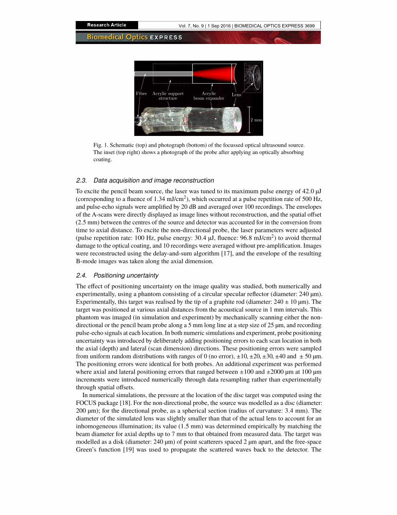
At an axial distance of 3 mm from the pencil beam source, the acoustic field is tightly confined(Fig. 2, left) to a circle with a diameter of approximately 0.3 mm. Propagating this acoustic fieldto different axial distances (Fig. 2, middle) reveals that the narrowest beam waist coincides withthe geometrical focus of the coated lens (radius of curvature: 3.4 mm), that the beam exhibitscircular symmetry around the axial axis, and that the beam diameter is narrower than 1 mm foraxial distances up to 7 mm. As the ultrasound is not focused upon reception, the beam diameter isequivalent to the lateral resolution. The bi-polar pulse shape and large bandwidth (−6 dB relativeto peak power between 8 and 33 MHz; Fig. 2, right) result in a high axial resolution of 75 µm.The peak acoustic amplitude ranges between 0.35 and 1.0 MPa for axial distances up to 7 mm,and is limited by the maximum pulse energy of the applied laser.
Peak pressureLateralElevational P
eak pressu
re [MP
a]
1.0
0.8
0.6
0.4
Axial distance from lens [mm]0 1 2 3 4 5 6 7
Lat
eral
/ e
leva
tion
albea
m w
aist
[m
m]
1.2
0.8
0.4
1.0
0.6
0.2
Elevational [mm]0 1 2 3 4 5
Lat
eral
[m
m]
0
1
2
3
4
5
-2 dB
-6
-10
-14
-18
Frequency [MHz]0 10 20 30 40 50
Pow
er [dB
]10
0
-10
1
0
-1Pre
ssure
[M
Pa]
1.5 2.0 2.5 3.0Time [ms]
Fig. 2. Left: maximum intensity of the transmitted acoustic field measured at an axialdistance of 3 mm with the full-width half maximum contour indicated by the dotted bluecurve. Middle: spatial extent of the acoustic beam in the elevational (black solid curve)and lateral direction (black dashed curve), together with the peak acoustic amplitude (reddash-dotted curve), as a function of axial depth. The acoustic data were measured at a distanceof 3 mm and numerically propagated to the remaining depths. Right: power spectrum ofthe A-scan (shown in the inset) corresponding to the peak acoustic intensity measured at adistance of 3 mm. The dashed red line indicates the −6 dB level relative to peak power usedto measure the bandwidth of the transmitted signal.
3.2. Phantom imaging - positioning uncertainty
Both simulations and experiments confirm that the presence of modest positioning uncertainty(≤ 30 µm) introduces severe artefacts in images obtained with the non-directional probe (Fig. 3).While the actual object can still be recognised, the artefacts have nearly the same magnitude asthe actual signal, and hence the image has strongly reduced contrast. Similar images obtainedfor the full set of tested positioning error ranges (Visualization 1 and Visualization 2) revealthat significant artefact levels are introduced by positioning errors as small as ≤ 20 µm. Bycomparison, images obtained in both simulations and experiments using the pencil beam probeare insensitive to probe positioning errors of up to ±300 µm. While minor distortions can be
Vol. 7, No. 9 | 1 Sep 2016 | BIOMEDICAL OPTICS EXPRESS 3700
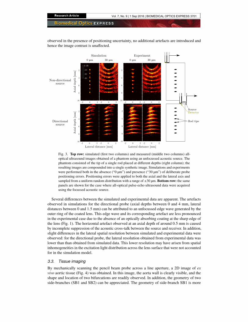
observed in the presence of positioning uncertainty, no additional artefacts are introduced andhence the image contrast is unaffected.
-2 0 2 -2 0 2
2
4
6
8
10
Simulation Experiment0 mm 30 mm
-2 0 2 -2 0 2
2
4
6
8
10
0 dB
-10
-20
-30
2
4
6
8
10-2 0 2 -2 0 2
0 mm 30 mm
-2 0 2 -2 0 2
2
4
6
8
10
Directionalsource
Non-directionalsource
Lateral distance [mm] Lateral distance [mm]
Axi
al d
epth
[m
m]
Axi
al d
epth
[m
m] Detector
Source
Rod tips
Fig. 3. Top row: simulated (first two columns) and measured (middle two columns) all-optical ultrasound images obtained of a phantom using an unfocussed acoustic source. Thephantom consisted of the tip of a single rod placed at different depths (right column); theresulting images are compounded into a single synthetic image. Simulations and experimentswere performed both in the absence (“0 µm”) and presence (“30 µm”) of deliberate probepositioning errors. Positioning errors were applied to both the axial and the lateral axis andsampled from a uniform random distribution with a range of ±30 µm. Bottom row: the samepanels are shown for the case where all-optical pulse-echo ultrasound data were acquiredusing the focussed acoustic source.
Several differences between the simulated and experimental data are apparent. The artefactsobserved in simulations for the directional probe (axial depths between 0 and 4 mm, lateraldistances between 0 and 1.5 mm) can be attributed to an unfocussed edge wave generated by theouter ring of the coated lens. This edge wave and its corresponding artefact are less pronouncedin the experimental case due to the absence of an optically absorbing coating at the sharp edge ofthe lens (Fig. 1). The horizontal artefact observed at an axial depth of around 0.5 mm is causedby incomplete suppression of the acoustic cross-talk between the source and receiver. In addition,slight differences in the lateral spatial resolution between simulated and experimental data wereobserved: for the directional probe, the lateral resolution obtained from experimental data waslower than than obtained from simulated data. This lower resolution may have arisen from spatialinhomogeneities in the excitation light distribution across the lens surface that were not accountedfor in the simulation model.
3.3. Tissue imaging
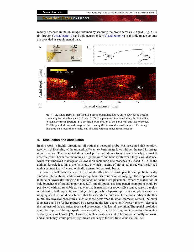
By mechanically scanning the pencil beam probe across a line aperture, a 2D image of exvivo aortic tissue (Fig. 4) was obtained. In this image, the aorta wall is clearly visible, and theshape and location of two bifurcations are readily observed. In addition, the geometry of twoside-branches (SB1 and SB2) can be appreciated. The geometry of side-branch SB1 is more
Vol. 7, No. 9 | 1 Sep 2016 | BIOMEDICAL OPTICS EXPRESS 3701
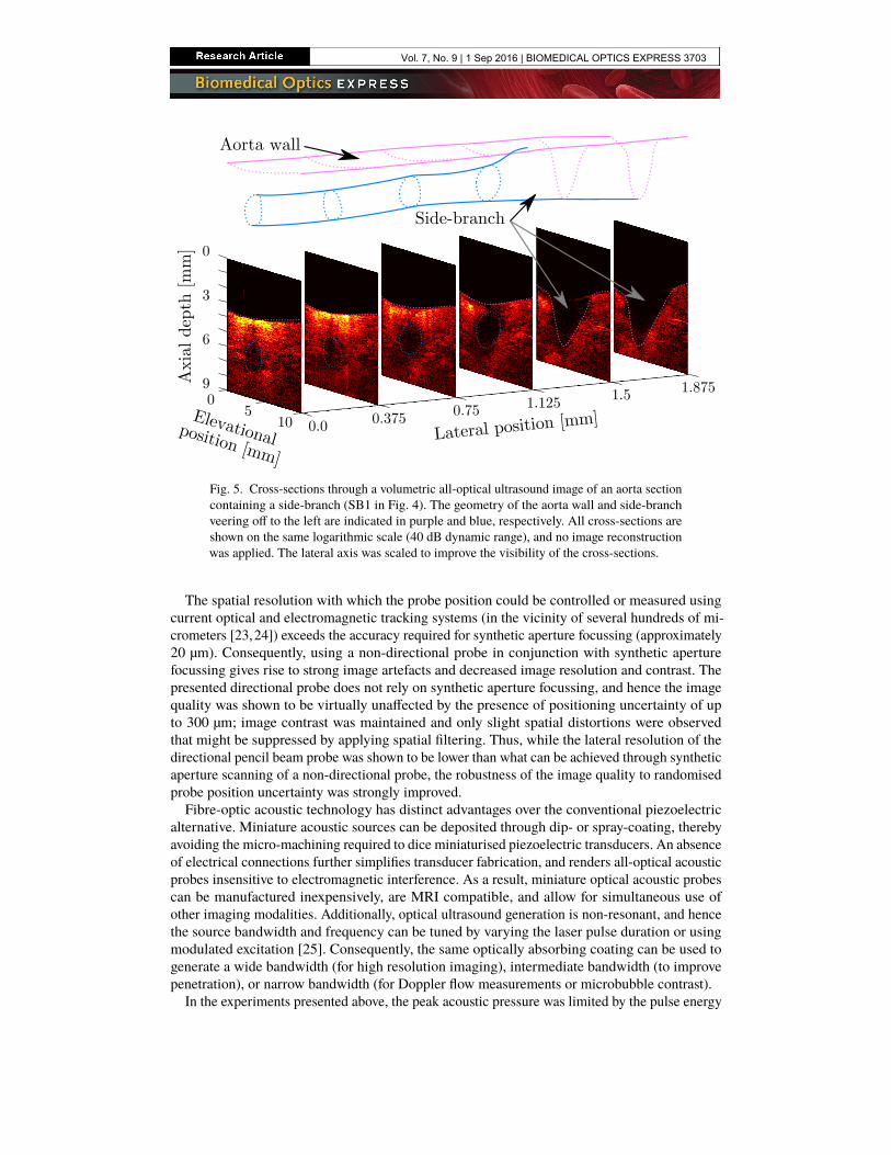
readily observed in the 3D image obtained by scanning the probe across a 2D grid (Fig. 5). Afly-through (Visualization 3) and volumetric render (Visualization 4) of this 3D image volumeare provided as supplemental data.
0 5 10 15 20 25
0
2
4
6
8
Lateral distance [mm]
Axi
al d
epth
[m
m]
0 -12.5 -25 dB
SB1 SB2
C.
SB1 SB2A.
10 mm SB1 SB2
B.
Fig. 4. A. Photograph of the focussed probe positioned above an ex vivo aortic sectioncontaining two side-branches (SB1 and SB2). The probe was translated along the dotted lineto scan a synthetic aperture. B. Schematic cross-section of the aorta wall and side-branches.C. All-optical ultrasound image acquired using the focussed acoustic source. The image,displayed on a logarithmic scale, was obtained without image reconstruction.
4. Discussion and conclusion
In this work, a highly directional all-optical ultrasound probe was presented that employsgeometrical focussing of the transmitted beam to form image lines without the need for imagereconstruction. The presented directional probe was shown to generate a nearly collimatedacoustic pencil beam that maintains a high pressure and bandwidth over a large axial distance,which was employed to image an ex vivo aorta containing side-branches in 2D and in 3D. To theauthors’ knowledge, this is the first study in which imaging of biological tissue was performedwith a geometrically focused optically transmitted acoustic beam.
Given its small outer diameter of 2.5 mm, the all-optical acoustic pencil beam probe is ideallysuited to interventional and endoscopic applications of ultrasound imaging. These applicationsinclude endovascular imaging for guidance of aortic stent placement, where visualisation ofside-branches is of crucial importance [20]. An all-optical acoustic pencil beam probe could bepositioned within a steerable tip catheter that is manually or robotically scanned across a regionof interest to build up an image. Using this approach in laparoscopic or fetoscopic contexts, animaging aperture could be achieved that far exceeds the port size. For compatibility with otherminimally invasive procedures, such as those performed in small-diameter vessels, the outerdiameter could be further reduced by decreasing the lens diameter. However, this will decreasethe tightness of the acoustical focus and consequently the lateral resolution. The spatial resolutioncould be improved through spatial deconvolution, particularly using implementations involvingspatially varying kernels [21]. However, such approaches tend to be computationally intensive,and as such they would present significant challenges for real-time visualisation [22].
Vol. 7, No. 9 | 1 Sep 2016 | BIOMEDICAL OPTICS EXPRESS 3702
Axi
al d
epth
[m
m] 0
3
6
9
Elevational position [mm]
05
10Lateral position [mm]0.0 0.375 0.75 1.125 1.5 1.875
Side-branch
Aorta wall
Fig. 5. Cross-sections through a volumetric all-optical ultrasound image of an aorta sectioncontaining a side-branch (SB1 in Fig. 4). The geometry of the aorta wall and side-branchveering off to the left are indicated in purple and blue, respectively. All cross-sections areshown on the same logarithmic scale (40 dB dynamic range), and no image reconstructionwas applied. The lateral axis was scaled to improve the visibility of the cross-sections.
The spatial resolution with which the probe position could be controlled or measured usingcurrent optical and electromagnetic tracking systems (in the vicinity of several hundreds of mi-crometers [23,24]) exceeds the accuracy required for synthetic aperture focussing (approximately20 µm). Consequently, using a non-directional probe in conjunction with synthetic aperturefocussing gives rise to strong image artefacts and decreased image resolution and contrast. Thepresented directional probe does not rely on synthetic aperture focussing, and hence the imagequality was shown to be virtually unaffected by the presence of positioning uncertainty of upto 300 µm; image contrast was maintained and only slight spatial distortions were observedthat might be suppressed by applying spatial filtering. Thus, while the lateral resolution of thedirectional pencil beam probe was shown to be lower than what can be achieved through syntheticaperture scanning of a non-directional probe, the robustness of the image quality to randomisedprobe position uncertainty was strongly improved.Fibre-optic acoustic technology has distinct advantages over the conventional piezoelectric
alternative. Miniature acoustic sources can be deposited through dip- or spray-coating, therebyavoiding the micro-machining required to dice miniaturised piezoelectric transducers. An absenceof electrical connections further simplifies transducer fabrication, and renders all-optical acousticprobes insensitive to electromagnetic interference. As a result, miniature optical acoustic probescan be manufactured inexpensively, are MRI compatible, and allow for simultaneous use ofother imaging modalities. Additionally, optical ultrasound generation is non-resonant, and hencethe source bandwidth and frequency can be tuned by varying the laser pulse duration or usingmodulated excitation [25]. Consequently, the same optically absorbing coating can be used togenerate a wide bandwidth (for high resolution imaging), intermediate bandwidth (to improvepenetration), or narrow bandwidth (for Doppler flow measurements or microbubble contrast).
In the experiments presented above, the peak acoustic pressure was limited by the pulse energy
Vol. 7, No. 9 | 1 Sep 2016 | BIOMEDICAL OPTICS EXPRESS 3703
provided by the excitation laser; after prolonged use of the probe, no deterioration in acousticperformance of the sound-generating coating on the directional probe was observed. In particular,the cross-talk amplitude and wavefront monitored over a period of 4.5 hours varied by lessthan 3 %. However, preliminary experiments not reported here suggest the damage thresholdfluence for the coating is up to 50 times higher than the fluence used in this work. Therefore,light sources with higher pulse energies could be employed to increase the peak acoustic pressureto tens of MPa, thereby enabling therapeutic use, as previously suggested by Baac et al. [12].The peak acoustic amplitude could be further increased by switching to materials that convertoptical to acoustic energy more efficiently, such as those based on multi-walled carbon nanotubesovercoated with PDMS [12,14].Focussed or collimated acoustical beams for use in biomedical imaging have been generated
through various approaches. For instance, an annular array of piezoelectric transducers (diameter:25 mm) has been used to generate a non-diffracting Bessel beam [26]. Alternatively, minia-ture two-dimensional arrays (diameter: 2.5 mm) comprising either piezoelectric or capacitivemicromachined ultrasound transducers (CMUTs) can be used to dynamically focus acousticbeams at different locations and depths [27]. Furthermore, single miniature geometrically fo-cussed piezoelectric transducers (diameter: 5 mm) have previously been used in commercialultrasound scanners [28], where images were generated by rapidly wobbling the transducer.While miniaturised piezoelectric or CMUT sources can yield bandwidths and pressures that aresimilar to those obtained with the all-optical probes presented in this study, their significantlyhigher manufacturing costs prohibit widespread interventional use where probes are treated asdisposables. However, focussed piezoelectric or CMUT transducers can typically be used forboth acoustic transmission and detection, and hence a better lateral resolution than demonstratedin this work can be obtained. Similarly, a more directional fibre-optic acoustic detector could beused to improve the lateral resolution. Alternatively, lenses with different diameters or radii ofcurvature could be used to manufacture acoustic sources that generate a tighter focus or a largerdepth of field.This study demonstrates how changing the geometry of the optical acoustic source enables a
different imaging approach to all-optical ultrasound imaging that is robust to probe positioninguncertainty. With the resulting probe, it is expected that high quality images can be obtained invivo using probe manipulation and tracking methods that are suitable to an interventional setting.
Funding
European Research Council (ERC) (European Starting Grant 310970 MOPHIM); InnovativeEngineering for Health award by the Wellcome Trust [WT101957] and the Engineering andPhysical Sciences Research Council (EPSRC) [NS/A000027/1]; European Union project FAMOS(FP7 ICT, Contract 317744).
Acknowledgments
The authors thank Dr Sandy Mosse for assistance with the experimental set-up.
Vol. 7, No. 9 | 1 Sep 2016 | BIOMEDICAL OPTICS EXPRESS 3704