programmable logic controller - farnell element14 programming tool (kglwin) on-line editing...
TRANSCRIPT

ISO 9001
Programmable Logic Controller

0101
Programming
Network
Performance
Functions
ALL in

Aiming at the Compactness and High Function
Powerful programming Tool (KGLWIN)
°· High function and performance with Exclusive MPU chip- Execution speed : 0.5µs/step
- Program capacity : 7ksteps
°· Various built-in functions for the enlarging application fields- One(1) High speed counter (1~16kHz, 2~8kHz)
- One(1) Pulse train output (2kHz)
- Eight(8) PID control with auto tuning
- Eight(8) Pulse catch inputs
- Filtered input
- Eight(8) External interrupt inputs
- One(1) RS-232C I/F (dedicated, user defined, Modbus protocol)
°· Windows-based tool (Windows 95, 98 and NT )
°· Applicable to all the K series
°· Ladder diagram, Mnemonic language supported
°· Possible to Edit a program in RUN mode
°· Forced I/O On/Off
°· Display the comments in a program
°· Available all printers supported by Wndows
°· Powerful debuggings- Execution step by step
- Execution to a given step
- Execution till the data becomes a given value.
- Execution the cycles at the No. of given times
0302
ONE, All for your needs

02020303
P00 P01 P02
One high-frequency pulse output(max. 2kpps) enables to build stepping motor and simple positioning control systems.
It can be applied for temperature control, Pressure control, Flow control in the fields such as Chemical and processIndustries, Glass and ceramics, Wood and paper industry, Food & Drink industry and Furnace, etc.
Single high speed counter up to 16kHz enables and resets input, as up/down counter for connecting incrementalencoders or high speed pulse generator. This counter is independent of the CPU ladder logic execution, so counting isnot affected(16kHz for 1phase, 8kHz for 2phases, 24bits) by the scan time.
Sensor
Analog Input
Analog OutputHeater
External preset input(24Vdc)
CommonPhase A
Phase B
Fan
Com 0
Pulse output
Direction output
Stepping motor
Motor drive
Conveyor
Sensor
Digital Output
PG
Motor
Main Unit
Main Unit Analog I/O Module
120
Furnace
Applications
Single High Speed Up / Down Counter (built-in)
Eight (8) PID loops with auto tuning (built-in)
Pulse Output (built-in, TR type)

0404
Pulse catch inputs can capture fast pulse inputs that cannot normally be detected during the nomal input cycling.Max. 8 different pulse catch inputs(P000~P007) are available and pulses with width as small as 0.2ms can be captured. You can configure these inputs in the basic parameter setting of KGLWIN.
Inputs with filters prevent the CPU from reading abnormal inputs and reduce the possibility of input malfunction.The fillter time can be programmed from 0 to 15ms in 1ms increments.
Flow Meter
Watt Hour Meter
Flow Meter
Watt Hour Meter
Shorter pulses than filter time are ignored
Input signal
Pulse input
Internal statusScan 1 Scan 2 Scan 3
Internal status
Input signal
Internal status
Filter time Filter time
TIME
000000
Discrete inputs with filters (built-in)
000000
Eight (8) Pulse catch Inputs (built-in)
0505
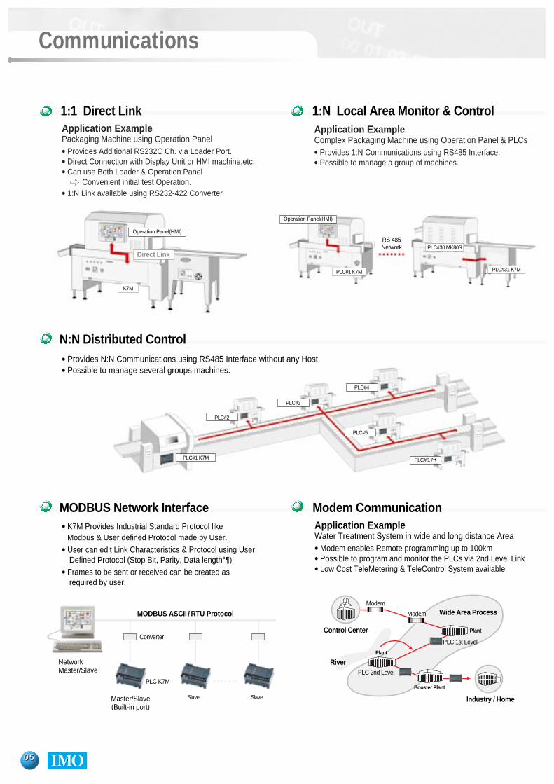
Communications
Application Example Packaging Machine using Operation Panel
• Provides Additional RS232C Ch. via Loader Port.• Direct Connection with Display Unit or HMI machine,etc.• Can use Both Loader & Operation Panel
Convenient initial test Operation.• 1:N Link available using RS232-422 Converter
Application ExampleComplex Packaging Machine using Operation Panel & PLCs
• Provides 1:N Communications using RS485 Interface.• Possible to manage a group of machines.
1:1 Direct Link 1:N Local Area Monitor & Control
• K7M Provides Industrial Standard Protocol like Modbus & User defined Protocol made by User.
• User can edit Link Characteristics & Protocol using User Defined Protocol (Stop Bit, Parity, Data length°¶)
• Frames to be sent or received can be created asrequired by user.
MODBUS Network Interface Modem Communication
Industry / Home
Wide Area Process
River
Modem
Modem
PLC 2nd Level
PLC 1st Level
Booster Plant
Plant
Plant
Application ExampleWater Treatment System in wide and long distance Area
• Modem enables Remote programming up to 100km• Possible to program and monitor the PLCs via 2nd Level Link• Low Cost TeleMetering & TeleControl System available
N:N Distributed Control• Provides N:N Communications using RS485 Interface without any Host.• Possible to manage several groups machines.
PLC#1 K7M
PLC#30 MK80S
PLC#31 K7M
PLC#1 K7M
PLC#2
PLC#3
PLC#4
PLC#5
PLC#6,7°
K7M
RS 485Network
Direct Link
Operation Panel(HMI)
Operation Panel(HMI)
Control CenterConverter
NetworkMaster/Slave
MODBUS ASCII / RTU Protocol
Master/Slave(Built-in port)
PLC K7M
Slave Slave

0606
Programming Tool (KGLWIN)
On-line Editing
Debugging
Powerful debuggings- Execution step by step- Execution to a given step- Execution till the data becomes a given value.- Execution the cycles at the No. of given times
Overview- Windows-based tool (Windows 95, 98 and NT)- Applicable to all the MASTER-K series- Ladder diagram, Mnemonic language supported- Remote programming via network is available- Several windows can be displayed in a screen- Display the comments in a program Available all printers supported by Windows
- Possible to Edit a program in RUN mode- Forced I/O On/Off and change the value of data
On-line Editing
Multi-Window

0707
Specification
Perfomance specification of main module
Item Specifications Remarks
Program control methodCyclic operation of stored program,interrupt task operation
I/O control method Refresh method, Direct I/O method
Mnemonic programLadder Diagram
30 kinds
218 kinds
0.5 µs/step
7ksteps
20 ~ 80 points
P0000 ~ P013F
M0000 ~ M191F
K0000 ~ K031F Non volatile area
L0000 ~ L063F
F0000 ~ F063F
C000 ~ C255
S00.00 ~ S99.99
D0000 ~ D4999
100ms : T000 ~ T19110ms : T192 ~ T255
Changeable byparameter setting
Programming language
Processing speed
Program capacity
I/O points
Basic
Application
I/O area (P)
Aux. Area (M)
Keep area (K)
Link area (L)
Special area (F)
Timer (T)
Counter (C)
Step control area (S)
Data register (D)
PID control
Counting speed
Counting modes
Highspeedcounter
Multiplication
Pulse input
Pulse output
External interrupt
Input filter
Cnet I/F Function(RS-232C)
No. of instructions
Data memory
Built-in special
function
Controlled by instructionAuto tuning, Forward/reverse actionForced output, Operation scan time setup
Dedicated protocolMODBUS protocolUser-defined protocol
1-phase: 16kHz(1 channel)2-phase: 8kHz(1 channel)
3 counting modes- 1 phase, Up/down count with program input- 1 phase, Up/down count with B phase input- 2 phase, Up/down count with phase difference
select one of 1, 2, or 4
Pulse width: 0.2 ms, 8 points
1x 2 kHz (Transistor output only)
8 points, 0.4ms
0 ~ 15ms
*Remark) K7M-DR10S(/DC), K7M-DT10,:Built in RS232 and RS-485 I/F, not available for Cnet I/F module

0808
Input
Output(Transistor)
Insulation Device
Rated Input VoltageRated Input Current
Operation VoltageMax. Simultaneously On
On Voltage / CurrentOff Voltage / Current
Input ImpedanceOff OnOn Off
ResponseTime
Output(Relay)
Operation IndicatorExternal wiring
* Remark K7M-DR10S/DC, DR20S/DC, DR30S/DC, DR40S/DC, DR60S/DC : DC 12~24V powered.
Photo couplerDC12~24V
DC12V 4.5mA, DC24V 9mADC10.2~28.8V (Ripple : 5% or less)
100% Simultaneously onMore than DC9.5V/3.5mA (P000~P002 : 6.3mA)
Less than DC5V/1.8mA (P000~P002 : 6.3mA)About 2.7K (P000~P002 : 1.5K )
1~15ms1~15ms
LEDTerminal block (M3 x 6 screw)
ItemType K7M-DR10S(/DC) K7M-DR20S(/DC) K7M-DR30S(/DC) K7M-DR40S(/DC) K7M-DR60S(/DC) G7E-DR10A
K7M-DT10S K7M-DT20S K7M-DT30S K7M-DT40S K7M-DT60S -Input Point 6 12 18 24 36 6
Insulation Device
Rated Load Voltage/ Current
Minimum Input
Max. Load VoltageMax. Switching Frequency
Surge Killer
Off OnOn Off
ResponseTime
Operation IndicatorExternal wiring
Item Type K7M-DR10S(/DC) K7M-DR20S(/DC) K7M-DR30S(/DC) K7M-DR40S(/DC) K7M-DR60S(/DC) G7E-DR10A-
Switching DeviceOutput Pointt 4 8 12 16 24 4
MechanicalLifetime ofRelay Electrical
Relay
Relay
DC24V / 2A (Resistive load), AC220V / 2A (COS¨ =1) 1 Point2A/1 Point/com, 4A/2 Points/com, 4A/4 Points/com
DC5V/1mA
AC250V DC110V1,200 Times/Hour
NoneOver 0.1 million timesOver 20 million times
Within 10msWithin 12ms
LEDTerminal block (M3 x 6 screw)
Rated Load VoltageRated Load Current
Common Method
Operation IndicatorInsulation Device
Surge Killer
Off OnOn Off
ResponseTime
Internal Power Consumption
Item Type K7M-DT10S K7M-DT20S K7M-DT30S K7M-DT40S K7M-DT60S --Output Pointt 4 8 12 16 24 -
DC 12/240.5A/1 Point, 3A/1com
Less than 2ms
8 Points / 1com, Sink type
LEDPhoto couplerClamp diode
170mA
Less than 2ms

Analog PotentiometerModule (G7F-AT2A)
Cnet I/F Module(G7L-CUEB, G7L-
CUEC)
Analog I/O module(G7F-ADHA)
- Four analog potentiometer can beused on the job manually to adjust set Points such as timer values ofother variables, without going intoPLC program.
- Adjustment can be made from thefront part of the module using variable resistors
- RS-422/485 interface enables communication between computerand 32 PLCs using the multidrop System(G7L-CUEC)
- MODBUS Master/Slave mode canbe used on a MODBUS RTU or ASCII mode
- Long distance communicationthrough RS-232C modem connection(G7L-CUEB)
- Communication parameter setting can be made in Programming Tool(KGLWIN)
Option Module
Analog input
Digital Output ResolutionVoltage/Current Selection
Analog Input Channels
Absolute Maximum Input
Digital Output Resolution
Analog Output
Voltage/Current SelectionAnalog Input Channels
Absolute Maximum Input
D/A part
A/D part
Item Specifications
Maximum Resolution
AccuracyConversion TimeInsulation DeviceExternal WiringPower supply
Current consumptionWeight
VoltageCurrent
VoltageCurrent
Voltage
Current
VoltageCurrent
DC 0~10VDC 0~20mADC 0~20mA
Power Specification
0909
Option module
DC0~10VDC0~20mA or 4~20mA
12bit (0~4,000)• Selected by dip switch • Short V and 1 terminal for current Input
2channels/moduleDC+12V
DC+25mA12bit (0~4,000)
DC0~10V (load impedance 2KΩ-1MΩ)DC0~20mA (load impedance 560Ω)DC4~20mA (load impedance 560Ω)
Separated terminal1channels/module
DC+15VDC+24mA
2.5mV (1/4,000)5 (1/4,000)
6.25 (1/3,200)±0.5% or less (Full scale)
Scan time+1.5ms/channelsPhoto coupler between Input terminal and ground (No insulation between channels)
14Point terminal blockDC24V, 80mA DC5V, 10mA
240g
Dedicated Mode
KGMWIN ModeModbus Mode
User ModeDate BitStop BitStart BitParity
D/A part
Mode
Item SpecificationsRS-422, Modem (RS-232C)
Supports multidrop/1:1 communication via LG dedicated protocol Supports highspeed link service
Supports remote control via MASTER-K PLC protocolSupports master and slave function with MODBUS Protocol (ASCII, RTU)
Operated with user-defined protocol7 or 81 or 21 or 2
Even / Odd / NoneAsynchronous method
9,600/19,200/38,400/56,000/76,800/115,200/128,000 bpsParameter setting with KGLWIN software
500m180g
No. of TimersDigital Output Range
Timers SettingAccuracy of Timer
Current Consumption
Weight
Item Specifications4 Point
(8bit) 0~200Set by adjustable volume switch
±2.0% (Full acale)50mA200g
SynchronizationTransmission Speed
Setting MethodMax. Cable Length
Weight
TypeRated Voltage
Input Voltage RangeFrequency
Leakage CurrentDropout Tolerance
Output CurrentOutput Voltage
Over-Current Voltage
AC PoweredAC100~240 (Free voltage)
AC85~264V47~63Hz
20ms or less0.2A (Isolated from DC5V)
24V±10% (21.6~26.4V)0.22~1.5A
DC PoweredDC12~24V (Free Valtage)
DC10.2~28.8V-
2ms or less---
DC24VOutput
Input
Item Specifications
3mA or less (AC264V, 63Hz)

1010
Wiring Diagrams
System Configuration
P00P01
P40 P41 P42 P44 P46P47P45P43
P03 P05 P07 P09 P0BP02 P04 P06 P08 P0A OUT
AC100FG Com0 Com1 Com2 Com3
240U P40
P00 P02P01 P03 P05
P04
P41 P42 P43
P00P01
P40 P41 P42 P44 P46 P48 P4AP43 P45 P47 P49 P4B
P03 P05 P07 P09 P0B P0D P0F P11P02 P04 P06 P08 P0A P0C P0E P10
P00 P02 P04 P06 P08 P0A P0D P0F P11 P13 P15 P17P01 P03 P05 P07 P09 P0B P0C P0E P10 P12 P14 P16
P40 P41 P42 P44 P46 P48 P4A P4C P4EP43 P45 P47 P49 P4B P4D P4F
P00 P02 P04 P06 P08 P0A P0C P0E P10 P13 P15 P17 P19 P1B P1D P1F P21 P23P01 P03 P05 P07 P09 P0B P0D P0F P11 P12 P14 P16 P18 P1A P1C P1E P20 P22
P40 P41 P42 P44 P46 P48 P4A P4C P4E P50 P52 P54 P56P43 P45 P47 P49 P4B P4D P4F P51 P53 P55 P57
100 101 102 103 104 105 COMO
000 COM1 001 COM2 002 003COMO
K7M-DR20S K7M-DR30S
K7M-DR40S K7M-DR60S
G7E-DR10A
K7M-DR10S
Max. 3 Modules
• Base Unit• Processing speed : 0.5 µs • Program capacity : 7k steps • Type : K7M-DR10S K7M-DR10S/DC K7M-DT10SK7M-DR20S K7M-DR20S/DC K7M-DT20SK7M-DR30S K7M-DR30S/DC K7M-DT30SK7M-DR40S K7M-DR40S/DC K7M-DT40SK7M-DR60S K7M-DR60S/DC K7M-DT60S
Memory pack*When only basic unit is used : connect to the expansion connector of the basic unit.*When expansion unit is used : connect to the expansion connector of the last connected expansion unit.
• Available System• Digital I/Output : 2 Modules• Analog I/O : 2 Modules• Analog Timer : 3 Modules• Cnet I/F : 1 Module
• Expansion Unit• Digital I/Output : DC 6 Points/Relay 4Point• Analog I/O : Input 2ch, Output 1ch. • Analog timer : 4 Points• Cnet I/F: for RS-422/RS-232C (for modem)• Fnet (Master) • DevicNet (Slave) • Profibus-DP (Slave)
• Option Pack• RTC (Real time clock) Pack• Memory pack (For program back-up)
Max. 3Modules
Wiring Diagrams

IMO constantly endeavors to improveour products so that information
in this catalog is subject tochange without notice.
Product list
Dimensions
Type Part Number Specification Power Supply Remarks
1. Main unit 2. Expansion modules(Unit : mm )
K7M-DR10S 85
A B
135
135
165
215
85
95
145
145
175
225
95
K7M-DR20S
K7M-DR30S
K7M-DR40S
K7M-DR60S
G7E-DR10A
G7F-ADHA
G7F-AT2A
G7L-CUEB/C
*1 1 Buit-In High speed counter : 1 phase 16K pps, 2 phases 8K pps*2 K7M-DR10S (/DC), K7M-DT10S : built-In 1 RS-232C port and 1 RS-485 port available
Base Unit
Exp. Pack
Exp. Module
K7M-DR10S • 6 DC 12/24V Inputs • 4 Relay OutputsK7M-DR20S • 12 DC 12/24V Inputs • 8 Relay OutputsK7M-DR30S • 18 DC 12/24V Inputs • 12 Relay Outputs K7M-DR40S • 24 DC 12/24V Inputs • 16 Relay OutputsK7M-DR60S • 36 DC 12/24V Inputs • 24 Relay Outputs AC85~264VK7M-DT10S • 6 DC 12/24V Inputs • 4 Transistor Outputs (Free voltage)K7M-DT20S • 12 DC 12/24V Inputs • 8 Transistor OutputsK7M-DT30S • 18 DC 12/24V Inputs • 12 Transistor Outputs K7M-DT40S • 24 DC 12/24V Inputs • 16 Transistor OutputsK7M-DT60S • 36 DC 12/24V Inputs • 24 Transistor OutputsK7M-DR10S/ DC • 6 DC 12/24V Inputs • 4 Relay OutputsK7M-DR20S/ DC • 12 DC 12/24V Inputs • 8 Relay Outputs DC12~24VK7M-DR30S/ DC • 18 DC 12/24V Inputs • 12 Relay Outputs (Free voltage)K7M-DR40S/ DC • 24 DC 12/24V Inputs • 16 Relay OutputsK7M-DR60S/ DC • 36 DC 12/24V Inputs • 24 Relay Outputs
• Programming capacity : 7K steps• 1 High speed counter (16 KHz for 1 Phase, 8 KHz for 2 Phases)• 8 PID Loops with auto Tuning
Built-In functions• 8 Pulse catch Inputs (Min. 0.2ms)• Discrete Inputs with filters (0~15ms, each 1ms)• 8 External Interrupt Inputs (0.4ms)• 1 RS-232C and 1 Loader port
(Dedicated, userdefined, Modbus protocol available)G7E-DR10A • 6 DC 12/24V Inputs • 4 Relay OutputsG7F-ADHA • 2 Analog Inputs • 1 Analog OutputsG7L-CUEC • RS-422/485 Communication moduleG7L-CUEB • RS-232C Communication module (Modem available)G7L-PBEA • Profibus-DP slave moduleG7F-AT2A • Analog potentio meter, 4 pointsG7E-RTCA • Real time clock packG7M-M256 • Flash memory pack for program back-up (256Kbytes)
*1
*2
IMO Precision Controls Limited1000 North Circular RoadStaples Corner, London NW2 7JPTel : +44 (0)20 8452 6444 Fax: +44 (0)20 8450 2274Email: [email protected] IMOnline: www.imopc.com