arc hydro gp tools 2.0 - tutorial - esridownloads.esri.com/archydro/archydro/tutorial/doc/arc hydro...
TRANSCRIPT

ESRI 380 New York St., Redlands, CA 92373-8100, USA TEL 909-793-2853 FAX 909-793-5953 E-MAIL [email protected] WEB www.esri.com
Arc Hydro Geoprocessing Tools - Tutorial
Version 2.0 – October 2011

Arc Hydro GP Tools v 2.0 – Tutorial
October 2011 i
Copyright © 2011 Esri All rights reserved. Printed in the United States of America. The information contained in this document is the exclusive property of Esri. This work is protected under United States copyright law and other international copyright treaties and conventions. No part of this work may be reproduced or transmitted in any form or by any means, electronic or mechanical, including photocopying and recording, or by any information storage or retrieval system, except as expressly permitted in writing by Esri. All requests should be sent to Attention: Contracts Manager, Esri, 380 New York Street, Redlands, CA 92373-8100, USA.
The information contained in this document is subject to change without notice.

Arc Hydro GP Tools v 2.0 – Tutorial
October 2011 ii
TableofContents
Introduction 5 Objective 5
Loading Arc Hydro Tools Toolbox 5 Accessing the Arc Hydro Geoprocessing Tools Help 7 Arc Hydro Tools Configuration 9
Arc Hydro Setup 10 1. Set Target Locations 10 2. Set Batch Target Locations 13 3. Standard Geoprocessing Configuration 15
Terrain Preprocessing 16 1. Level DEM 17 2. DEM Reconditioning 22 3. Assign Stream Slope 25 4. Burn Stream Slope 27 5. Build Walls 28 6. Sink Prescreening 29 7. Sink Evaluation 29 8. Sink Selection 31 9. Fill Sinks 32 10. Flow Direction 33 11. Flow Direction with Sinks 34 12. Flow Accumulation 35 13. Stream Definition 36 14. Stream Segmentation 37 15. Flow Direction with Streams 37 16. Combine Stream Link and Sink Link 39 17. Catchment Grid Delineation 40 18. Catchment Polygon Processing 40 19. Drainage Line Processing 41 20. Adjoint Catchment Processing 42 21. Drainage Point Processing 43 22. Slope 44 23. Depression Evaluation 45 24. Adjust Flow Direction in Lakes 46
Terrain Preprocessing Workflows 47 1. Basic Dendritic Terrain Processing 47 2. Batch Processing 52 3. How to create your own model 55 4. How to run your own model in batch mode 62
Network Tools 66 1. Hydro Network Generation 66 2. Set Flow Direction 73 3. Store Flow Direction 75 4. Node Link Schema Generation 76
Attribute Tools 78 1. Assign HydroID 79
Arc Hydro GP Tools v2.0 – Tutorial
October 2011 iii
2. Assign UniqueID 80 3. Generate From/To Node for Lines 81 4. Find Next Downstream Line 83 5. Find Next Downstream Junction 85 6. Calculate Length Downstream for Edges 86 7. Calculate Length Downstream for Junctions 87 8. Store Area Outlets by Drainage Point Proximity 88 9. Store Area Outlets by Junction Intersect 88 10. Store Area Outlets by Next Downstream Area 88 11. Compute Global Parameters 89
Watershed Processing 97 1. Drainage Area Centroid 97 2. Longest Flow Path 99 3. Construct 3D Line 100 4. Smooth 3D Line 101 5. Flow Path Parameters from 2D Line 102 6. Flow Path Parameters from 3D Line 104 7. Batch Watershed Delineation 105 8. Interactive Delineation 109 9. Batch Subwatershed Delineation 113 10. Batch Watershed Delineation for Polygons 116 11. Delineate from Multiple Inlets and Outlets 118 12. Batch Global Watershed Delineation 121 1. Create Thiessen Polygons 127 2. Intersect Areas 128 3. Weighted Averages 130 4. Download Time Series Data 131 5. Export Data Cart to XML 131 6. Point TSValue to 3D Line 131 7. Update TSValue on Points 132 8. Convert 3D Line to Raster 132 9. Spatial Reference frin Raster 132
Terrain Morphology 133 Drainage Boundary Processing Toolset 135
1. Drainage Area Characterization 135 2. Drainage Boundary Definition 136 3. Drainage Boundary Direction 139 4. Cross Section Direction 142 5. Elevation-Width-Area Characterization 143 6. Station-Elevation Characterization 145 7. Drainage Boundary Smoothing 147 8. Drainage Connectivity Characterization 148
AH Connectivity Refinement Toolset 151 1. Sink Identification by HEP 151 2. Connect HydroJunctions 152 3. Connect Control Structure Junctions 160 4. Define Overland Preferential Node Link Schema 164 5. Flip Preferential Path 169 6. Add Point Structure HydroEdges to Preferential Link 173 7. Update Preferential Node Link Schema 175 8. Add Linear Structure HydroEdges to Preferential Link 178

Arc Hydro GP Tools v2.0 – Tutorial
October 2011 iv
9. Set Flow Direction Using Preferential Link 181 Grouping Toolset 183
1. Select Upstream Catchments using Preferential Node Link 183 2. Group Selected Catchment 186 3. Ungroup Selected Catchments 188 4. Generate Group Basin 190 5. Generate Group Junction 193 6. Generate Group Link 195
H&H Modeling 198 Time of Concentration Toolset 198
1. Generate TR55 Zone Grid 199 2. Compute Time of Concentration 200 3. Compute Travel Time for Preferential Link 202 4. Compute Time of Concentration for Group Basin 204
Green and Ampt Toolset 208 1. Accumulate Incremental TimeSeries 208 2. Create Green and Ampt Parameter Rasters 210 3. Compute Green and Ampt Parameters 213 4. Compute Green and Ampt Excess Rainfall 214 5. Export to ICPR Green and Ampt Parameters 219 6. Export to ICPR Green and Ampt Rainfall Excess 221
Map to Map Toolset 223 1. Export to DSS 223 2. Import from DSS 224 3. Run HMS 225 4. Run RAS 225 5. SDF to XML 226 6. Update RAS Flow 226
GeoICPR Toolset 228 1. Generate ICPR Node 228 2. Generate ICPR Link 233 3. Generate ICPR Basin 235 4. Export to ICPR 240 5. Import from ICPR 240
GIS Data Exchange 241 XML Exchange Toolset 241
1. Export GIS Data to XML 241 2. Import from XML 244 3. Transform XML 245
Excel Exchange Toolset 245 1. Export Tools Parameters 245 2. Map to Excel 246 3. Excel to Map 249
Arc Hydro GP Tools v 2.0 – Tutorial
October 2011 5
Introduction The purpose of this tutorial is to illustrate, step-by-step, how to access and use the Arc Hydro Geoprocessing (GP) tools that are installed by the standard Arc Hydro setup. The installation process is described in the document “Arc Hydro Tools 2.0 – Tutorial.pdf”. This document is targeted to an experienced water resources ArcGIS user who wants to learn how to use the new geoprocessing tools in Arc Hydro.
Objective In this tutorial, the user will perform drainage analysis on a terrain model using the geoprocessing tools instead of the standard Arc Hydro tools. The utility of the Arc Hydro geoprocessing tools is demonstrated by building models allowing running workflows in batch mode.
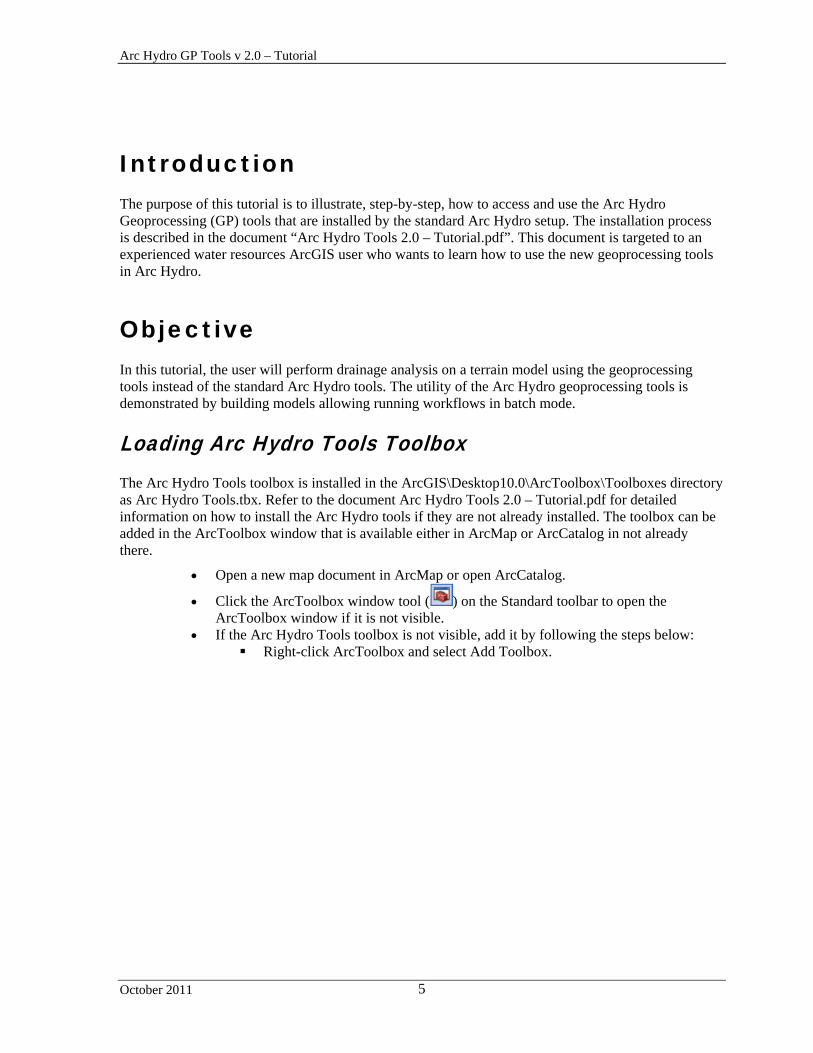
Loading Arc Hydro Tools Toolbox The Arc Hydro Tools toolbox is installed in the ArcGIS\Desktop10.0\ArcToolbox\Toolboxes directory as Arc Hydro Tools.tbx. Refer to the document Arc Hydro Tools 2.0 – Tutorial.pdf for detailed information on how to install the Arc Hydro tools if they are not already installed. The toolbox can be added in the ArcToolbox window that is available either in ArcMap or ArcCatalog in not already there.
Open a new map document in ArcMap or open ArcCatalog.
Click the ArcToolbox window tool ( ) on the Standard toolbar to open the ArcToolbox window if it is not visible.
If the Arc Hydro Tools toolbox is not visible, add it by following the steps below: Right-click ArcToolbox and select Add Toolbox.

Arc Hydro GP Tools v2.0 – Tutorial
October 2011 6
Browse to the ArcGIS toolboxes location (e.g. Toolboxes\System Toolboxes), select Arc Hydro Tools and click Open.
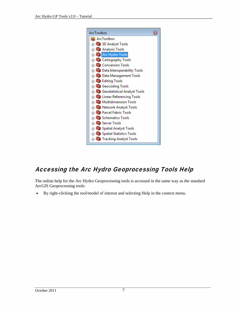
The Arc Hydro Tools toolbox is added to the list of available toolboxes.
Arc Hydro GP Tools v2.0 – Tutorial
October 2011 7
Accessing the Arc Hydro Geoprocessing Tools Help The online help for the Arc Hydro Geoprocessing tools is accessed in the same way as the standard ArcGIS Geoprocessing tools:
By right-clicking the tool/model of interest and selecting Help in the context menu.

Arc Hydro GP Tools v2.0 – Tutorial
October 2011 8
By opening the tool user interface and clicking the Tool Help button at the bottom of the right panel.
The first page accessed after clicking on Tool Help describes the parameters used by the tool. The link Learn more about how… on the page allows accessing a page describing in more details what the tool does.

Arc Hydro GP Tools v2.0 – Tutorial
October 2011 9
Arc Hydro Tools Configuration The standard Arc Hydro tools available in the Arc Hydro toolbar read their configuration from a XML file associated to the map document. This configuration is loaded from the template ArcHydroTools.xml configuration file stored in the ArcHydro\bin folder.
Note The raster and vector locations are not explicitly set in a new unsaved map document and in ArcCatalog. The geoprocessing tools will use in that case the standard Current Workspace for both those locations. This workspace may be set by right-clicking the ArcToolbox node in the ArcToolbox window and selecting Environments…
Arc Hydro GP Tools v2.0 – Tutorial
October 2011 10
Arc Hydro Setup This section describes how to setup non default Arc Hydro target locations used by the Arc Hydro tools. By default, the tools will create the default target vector and raster locations if they do not already exist and the user will not need to use this toolset.
1. Set Target Locations
This tool allows setting the target vector and raster locations in the XML in ArcMap as well as creating these workspaces if they do not already exist in both ArcMap and ArcCatalog.
The vector location may be set to a personal (existing or not) geodatabase or to a remote geodatabase. The tool will generate the unique ID table in that database if they do not already exist.
The raster location must be set to a file geodatabase (existing or not) or to a directory.
In ArcMap, the tool can work with multiple applications (Arc Hydro, GeoHMS, etc.). The Application Name input allows specifying the application to update (“HydroConfig” for Arc Hydro).
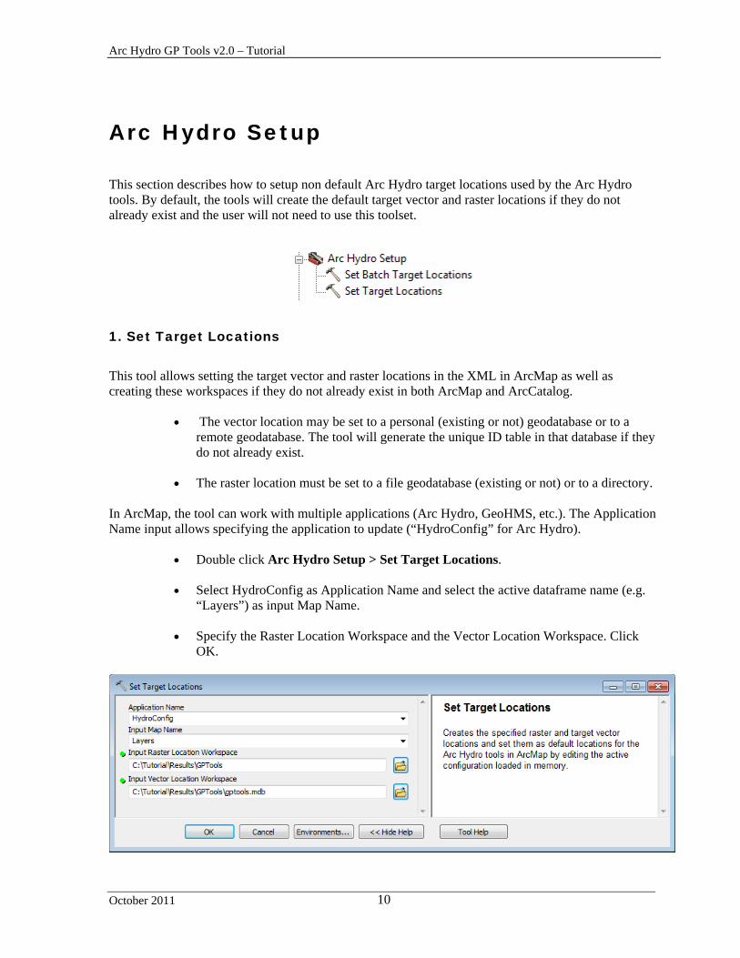
Double click Arc Hydro Setup > Set Target Locations.
Select HydroConfig as Application Name and select the active dataframe name (e.g. “Layers”) as input Map Name.
Specify the Raster Location Workspace and the Vector Location Workspace. Click
OK.

Arc Hydro GP Tools v2.0 – Tutorial
October 2011 11
The tool creates the target locations if they do not already exist. When run from ArcMap, the tool updates as well the Arc Hydro configuration loaded in memory with these locations. The RasterLocation and VectorLocation have been set to the specified values under a new MapView associated to the active dataframe (Layers). You can visualize the edits to the configuration in the XML loaded in memory in the map.
Add the Arc Hydro Tools toolbar in the map if not already there and select ApUtilities > XML Manager… and navigate to the node HydroConfig\MapViews\MpView(Layers)\RasterLocation where Layers is the name of the active dataframe in the map document. Right-click the RasterLocation node and select EditText to view the location set as target for the raster.
Click Cancel in the Edit window and close the XMLViewer by clicking on the cross in the top right corner.
Arc Hydro GP Tools v2.0 – Tutorial
October 2011 12
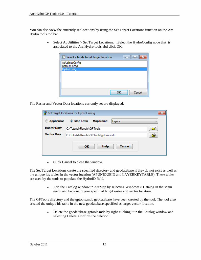
You can also view the currently set locations by using the Set Target Locations function on the Arc Hydro tools toolbar.
Select ApUtilities > Set Target Locations…,Select the HydroConfig node that is associated to the Arc Hydro tools abd click OK.
The Raster and Vector Data locations currently set are displayed.
Click Cancel to close the window. The Set Target Locations create the specified directory and geodatabase if they do not exist as well as the unique ids tables in the vector location (APUNIQUEID and LAYERKEYTABLE). These tables are used by the tools to populate the HydroID field.
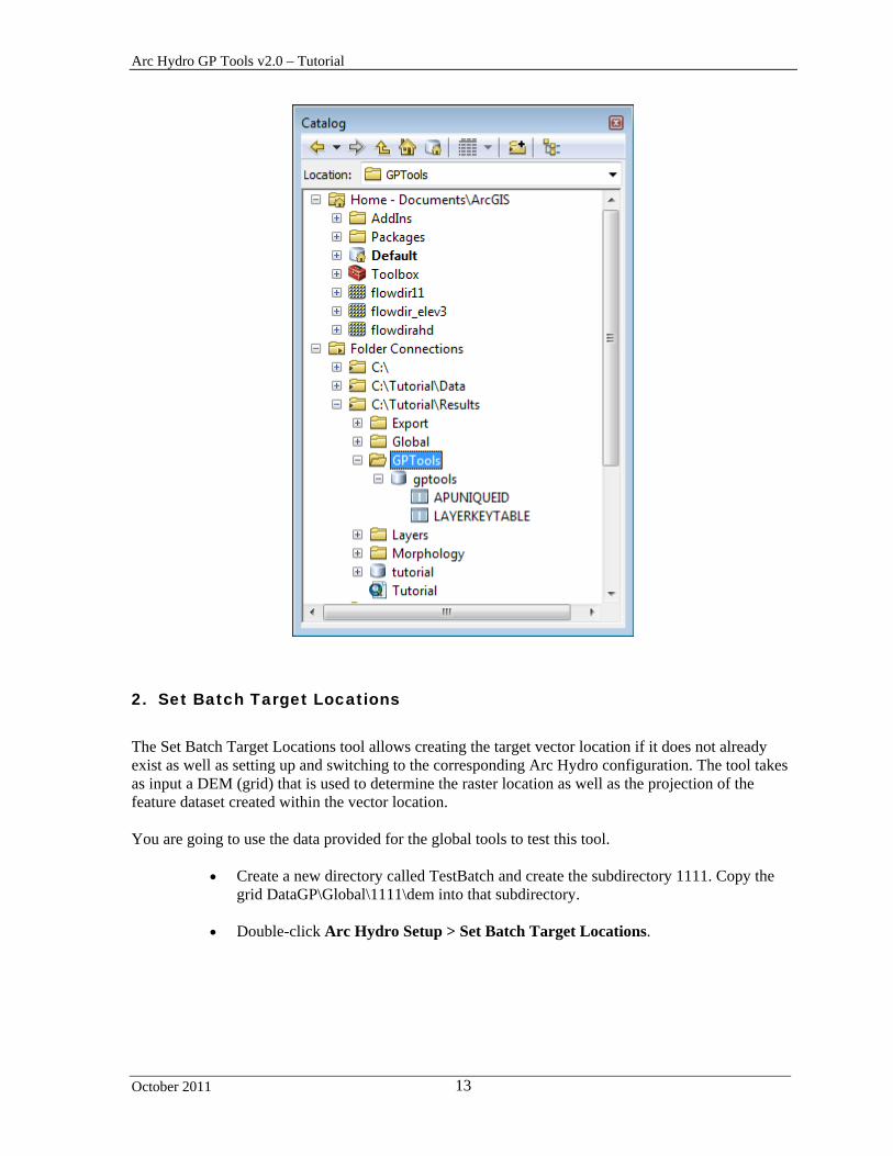
Add the Catalog window in ArcMap by selecting Windows > Catalog in the Main menu and browse to your specified target raster and vector location.
The GPTools directory and the gptools.mdb geodatabase have been created by the tool. The tool also created the unique ids table in the new geodatabase specified as target vector location.
Delete the geodatabase gptools.mdb by right-clicking it in the Catalog window and selecting Delete. Confirm the deletion.
Arc Hydro GP Tools v2.0 – Tutorial
October 2011 13
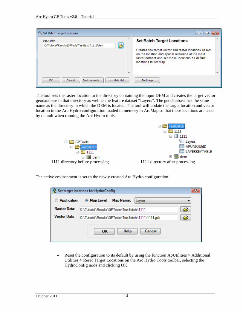
2. Set Batch Target Locations
The Set Batch Target Locations tool allows creating the target vector location if it does not already exist as well as setting up and switching to the corresponding Arc Hydro configuration. The tool takes as input a DEM (grid) that is used to determine the raster location as well as the projection of the feature dataset created within the vector location. You are going to use the data provided for the global tools to test this tool.
Create a new directory called TestBatch and create the subdirectory 1111. Copy the grid DataGP\Global\1111\dem into that subdirectory.
Double-click Arc Hydro Setup > Set Batch Target Locations.
Arc Hydro GP Tools v2.0 – Tutorial
October 2011 14
The tool sets the raster location to the directory containing the input DEM and creates the target vector geodatabase in that directory as well as the feature dataset “Layers”. The geodatabase has the same name as the directory in which the DEM is located. The tool will update the target location and vector location in the Arc Hydro configuration loaded in memory in ArcMap so that these locations are used by default when running the Arc Hydro tools.
1111 directory before processing 1111 directory after processing
The active environment is set to the newly created Arc Hydro configuration.
Reset the configuration to its default by using the function ApUtilities > Additional Utilities > Reset Target Locations on the Arc Hydro Tools toolbar, selecting the HydroConfig node and clicking OK.
Arc Hydro GP Tools v2.0 – Tutorial
October 2011 15
3. Standard Geoprocessing Configuration
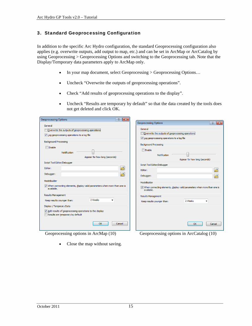
In addition to the specific Arc Hydro configuration, the standard Geoprocessing configuration also applies (e.g. overwrite outputs, add output to map, etc.) and can be set in ArcMap or ArcCatalog by using Geoprocessing > Geoprocessing Options and switching to the Geoprocessing tab. Note that the Display/Temporary data parameters apply to ArcMap only.
In your map document, select Geoprocessing > Geoprocessing Options…
Uncheck “Overwrite the outputs of geoprocessing operations”.
Check “Add results of geoprocessing operations to the display”.
Uncheck “Results are temporary by default” so that the data created by the tools does not get deleted and click OK.
Geoprocessing options in ArcMap (10) Geoprocessing options in ArcCatalog (10)
Close the map without saving.

Arc Hydro GP Tools v2.0 – Tutorial
October 2011 16
Terrain Preprocessing This section walks you through the Terrain Preprocessing tools in the geoprocessing environment. Note that each tool has a corresponding function in the standard Arc Hydro tools toolbar. If you are already familiar with the Arc Hydro tools, and comfortable with the ArcGIS geoprocessing tools, you may want to read through the first 2 tools (Level DEM and DEM Reconditioning) as an example of the Arc Hydro implementation of the geoprocessing tools and then jump to the next section, Terrain Preprocessing Workflows, to learn more on how building models and performing batch processing with the tools.
Note The preprocessing steps to use when preprocessing a terrain depend on the type of the terrain (dendritic, deranged, i.e. with sinks, combined) and on the type of analysis you want to perform. The objective of the section below is to step through all the tools, not to describe possible workflows. If you are interested in learning more about the terrain preprocessing workflows, refer to the document “Comprehensive terrain preprocessing using Arc Hydro tools”.
You can use the Tutorial data from the DataGP\SanMarcos directory.

Arc Hydro GP Tools v2.0 – Tutorial
October 2011 17
1. Level DEM
This tool levels the input Raw DEM by filling the cells covered by each lake up to the Fill Elevation value defined for that lake polygon.
Open a new map document. Warning Do not open from an existing map document or your configuration will not be reset in the new map but copied from the old map document.
Add the elevation grid \DataGP\SanMarcos\elev_cm and the Lakes feature class DataGP\SanMarcos\SanMarcos.gdb\Hydrography\NHDWaterbody into the Table of Contents of ArcMap.
Save the map as GPTools.mxd under Results\GPTools for example.
The Home folder is now set to the Result\GPTools directory where the map was saved.
Double-click Terrain Preprocessing > Level DEM.
Arc Hydro GP Tools v2.0 – Tutorial
October 2011 18
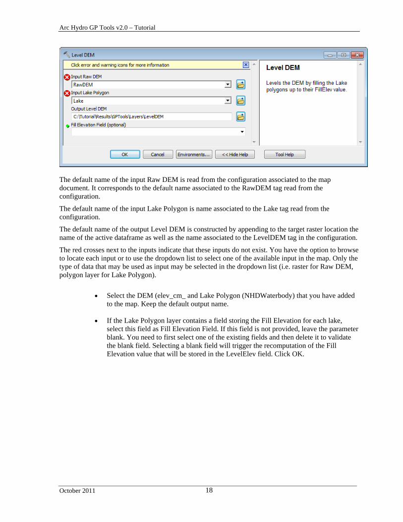
The default name of the input Raw DEM is read from the configuration associated to the map document. It corresponds to the default name associated to the RawDEM tag read from the configuration.
The default name of the input Lake Polygon is name associated to the Lake tag read from the configuration.
The default name of the output Level DEM is constructed by appending to the target raster location the name of the active dataframe as well as the name associated to the LevelDEM tag in the configuration.
The red crosses next to the inputs indicate that these inputs do not exist. You have the option to browse to locate each input or to use the dropdown list to select one of the available input in the map. Only the type of data that may be used as input may be selected in the dropdown list (i.e. raster for Raw DEM, polygon layer for Lake Polygon).
Select the DEM (elev_cm_ and Lake Polygon (NHDWaterbody) that you have added
to the map. Keep the default output name.
If the Lake Polygon layer contains a field storing the Fill Elevation for each lake, select this field as Fill Elevation Field. If this field is not provided, leave the parameter blank. You need to first select one of the existing fields and then delete it to validate the blank field. Selecting a blank field will trigger the recomputation of the Fill Elevation value that will be stored in the LevelElev field. Click OK.

Arc Hydro GP Tools v2.0 – Tutorial
October 2011 19
The tool processes the input DEM and displays the processing steps in the geoprocessing is not performed in background mode.
The tool performs the Level DEM step and adds the resulting LevelDEM to the map.
You can visualize the messages displayed when running the tools or intermediate geoprocessing tools called by the tools in the geoprocessing Results window.
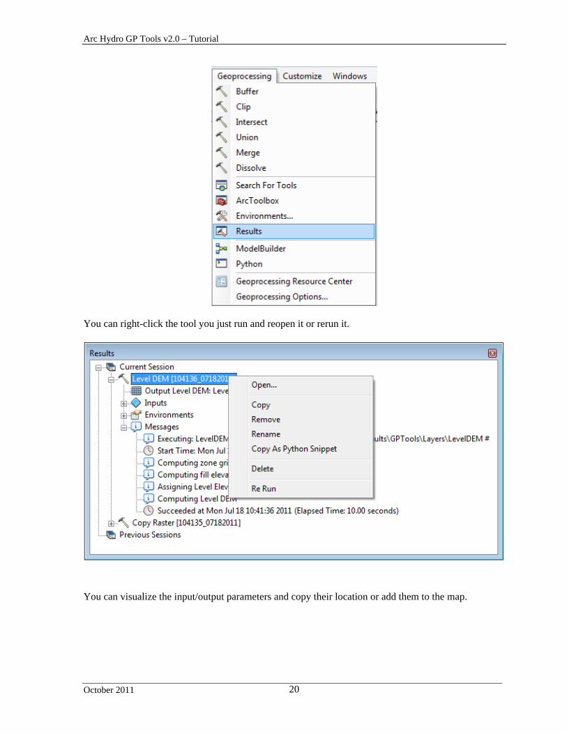
Select Geoprocessing > Results window to open the Results window.
Arc Hydro GP Tools v2.0 – Tutorial
October 2011 20
You can right-click the tool you just run and reopen it or rerun it.
You can visualize the input/output parameters and copy their location or add them to the map.

Arc Hydro GP Tools v2.0 – Tutorial
October 2011 21
You can also display the messages generated by the tools by right-clicking the Messages node and selecting View…
Close the Message window. The ouput leveldem grid has been created in the output target raster location. The picture below shows the new grid in the Table of Contents, in the map and in the Catalog window. It also shows the ArcToolbox windows containing the Arc Hydro geoprocessing tools and the geoprocessing Results window.

Arc Hydro GP Tools v2.0 – Tutorial
October 2011 22
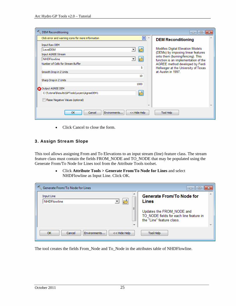
2. DEM Reconditioning
This tool performs the DEM Reconditioning step – it requires as input a DEM and stream feature class, as well as 4 parameters, and generates as output an AgreeDEM grid.
Add the stream feature class DataGP\SanMarcos.gdb\Hydrography\NHDFlowline into the map.
Double-click Terrain Preprocessing > DEM Reconditioning.
The default name of the input Raw DEM is set to the grid that was tagged as RawDEM when running the function Level DEM.
The default name of the input AGREE Stream is the name associated to the AgreeStream tag read from the configuration.
The default name of the output AGREE DEM is constructed by appending to the raster location the name of the active dataframe as well as the name associated to the AgreeDEM tag in the configuration.
The red cross next to the input indicates that this input does not exist. You have the option to browse to locate the input or to use the dropdown list to select one of the available input in the map. Only the type of data that may be used as input may be selected in the dropdown list (i.e. raster for Raw DEM, line layer for AGREE Stream).
Arc Hydro GP Tools v2.0 – Tutorial
October 2011 23
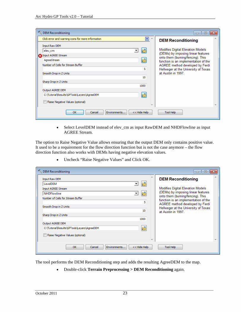
Select LevelDEM instead of elev_cm as input RawDEM and NHDFlowline as input AGREE Stream.
The option to Raise Negative Value allows ensuring that the output DEM only contains positive value. It used to be a requirement for the flow direction function but is not the case anymore – the flow direction function also works with DEMs having negative elevation values.
Uncheck “Raise Negative Values” and Click OK.
The tool performs the DEM Reconditioning step and adds the resulting AgreeDEM to the map.
Double-click Terrain Preprocessing > DEM Reconditioning again.
Arc Hydro GP Tools v2.0 – Tutorial
October 2011 24
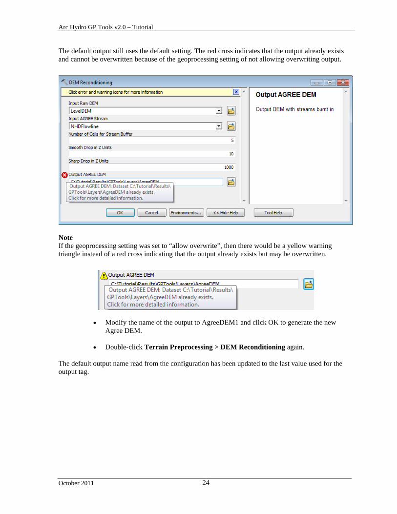
The default output still uses the default setting. The red cross indicates that the output already exists and cannot be overwritten because of the geoprocessing setting of not allowing overwriting output.
Note If the geoprocessing setting was set to “allow overwrite”, then there would be a yellow warning triangle instead of a red cross indicating that the output already exists but may be overwritten.
Modify the name of the output to AgreeDEM1 and click OK to generate the new Agree DEM.
Double-click Terrain Preprocessing > DEM Reconditioning again.
The default output name read from the configuration has been updated to the last value used for the output tag.
Arc Hydro GP Tools v2.0 – Tutorial
October 2011 25
Click Cancel to close the form.
3. Assign Stream Slope
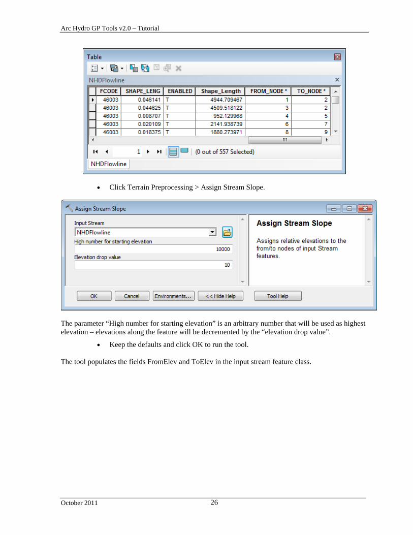
This tool allows assigning From and To Elevations to an input stream (line) feature class. The stream feature class must contain the fields FROM_NODE and TO_NODE that may be populated using the Generate From/To Node for Lines tool from the Attribute Tools toolset.
Click Attribute Tools > Generate From/To Node for Lines and select NHDFlowline as Input Line. Click OK.
The tool creates the fields From_Node and To_Node in the attributes table of NHDFlowline.
Arc Hydro GP Tools v2.0 – Tutorial
October 2011 26
Click Terrain Preprocessing > Assign Stream Slope.
The parameter “High number for starting elevation” is an arbitrary number that will be used as highest elevation – elevations along the feature will be decremented by the “elevation drop value”.
Keep the defaults and click OK to run the tool. The tool populates the fields FromElev and ToElev in the input stream feature class.

Arc Hydro GP Tools v2.0 – Tutorial
October 2011 27
4. Burn Stream Slope
This tool allows burning in a stream slope to force the water to flow in the digitized direction within the streams. The input steam feature must have the fields FromElev and ToElev populated.
Double-click Terrain Preprocessing > Burn Stream Slope.
Select as input DEM the DEM onto which you want to enforce the stream slope (e.g. AgreeDEM) and as input Stream a line feature class with populated FromElev and ToElev fields (e.g. NHDFlowline). Click OK.
The tool burns in the stream slope and generates an output “Stream Sloped DEM”. The output EditPoints feature class is an intermediate layer used in the burn in process.

Arc Hydro GP Tools v2.0 – Tutorial
October 2011 28
5. Build Walls
This tool allows building walls onto an input DEM. Two types of walls may be created:
- Outer walls – based on an input polygon feature class (Outer Wall Polygon) - Inner walls – based on an input polygon, line or point feature class (Inner Wall Feature)
Both types may be built at the same time, but at least one must be selected.
In addition, a Breach Line feature class may be provided as input, to ensure that they are “breaches” in the walls allowing the water to flow out.
Add DataGP\SanMarcos\SanMarcos.gdb\Hydrography\ProjectArea into the Table of Contents of ArcMap.
Double-click Terrain Preprocessing > Build Walls.
Select as input DEM the elevation grid onto which you want to enforce walls slope (e.g. StrSlpDEM) and click OK.
Enter the Inner Wall Height. The Outer Wall Height is twice this height. Enter a buffer (number of cells) for the Inner Walls. Default to 0, i.e. no buffer. Enter a buffer for the Breach Line. Default to 0, i.e. no buffer. Specify the name of the output Walled DEM. Select the Outer Wall Polygon layer (optional, e.g. ProjectArea) to ensure that the
outer boundary of the Catchment feature class matches a specific boundary. Select the Inner Wall Feature class (optional, e.g. ProjectArea) to ensure internal
watersheds/catchments boundary match specific input data. Select a Breach Line feature class (optional, e.g. NHDFlowline) that contains features
crossing the walls so that the water can flow out. Click OK.
Arc Hydro GP Tools v2.0 – Tutorial
October 2011 29
Upon successful completion of the process, the “WalledDEM” layer is added to the map.
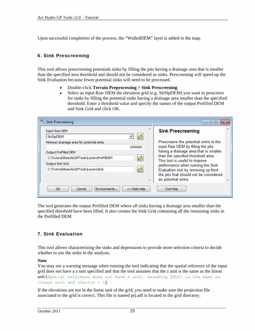
6. Sink Prescreening
This tool allows prescreening potentials sinks by filling the pits having a drainage area that is smaller than the specified area threshold and should not be considered as sinks. Prescreening will speed up the Sink Evaluation because fewer potential sinks will need to be processed.
Double-click Terrain Preprocessing > Sink Prescreening. Select as input Raw DEM the elevation grid (e.g. StrSlpDEM) you want to prescreen
for sinks by filling the potential sinks having a drainage area smaller than the specified threshold. Enter a threshold value and specify the names of the output Prefilled DEM and Sink Grid and click OK.
The tool generates the output Prefilled DEM where all sinks having a drainage area smaller than the specified threshold have been filled. It also creates the Sink Grid containing all the remaining sinks in the Prefilled DEM.
7. Sink Evaluation
This tool allows characterizing the sinks and depressions to provide more selection criteria to decide whether to use the sinks in the analysis.
Note You may see a warning message when running the tool indicating that the spatial reference of the input grid does not have a z unit specified and that the tool assumes that the z unit is the same as the linear unit (Spatial reference does not have z unit. Assuming ZUnit is the same as linear unit and zfactor = 1).
If the elevations are not in the linear unit of the grid, you need to make sure the projection file associated to the grid is correct. This file is named prj.adf is located in the grid directory.

Arc Hydro GP Tools v2.0 – Tutorial
October 2011 30
Set Zunits to 100 in the projection file of the PreFillDem if you are using the tutorial data to indicate that the elevations are in centimeters. Zunits represents the number of elevation unit in one meter (100 centimeters in 1 meter).
Double-click Terrain Preprocessing > Sink Evaluation.
Select as input DEM the Prefilled DEM created by the tool Sink Prescreening. Specify
the name of the output Sink Polygon and Sink Drainage Area feature classes and click OK.
The tool generates the Sink Polygon and Sink Drainage Area feature classes, and characterizes these features by populating area, depth, etc. so that the user can decide which sinks to retain for the analysis.

Arc Hydro GP Tools v2.0 – Tutorial
October 2011 31
8. Sink Selection
This tool allows selecting sinks based on various criteria. The sinks meeting the criteria will have their field IsSink populated with 1.
Open the Attributes table of SinkPoly and look at the values of the attributes.
Double-click Terrain Preprocessing > Sink Selection.
Select as input Deranged Polygon the SinkPoly feature class generated by the Sink Evaluation tool. Specify one or several selection criteria for the input polygons to be populated with IsSink=1, i.e. to be considered as real sinks in the following analyses.
Select whether to overwrite the existing records having IsSink set to 1 and click OK.
The tool populates the field IsSink with 1 for the polygons meeting the specified criteria.

Arc Hydro GP Tools v2.0 – Tutorial
October 2011 32
9. Fill Sinks
This tool fills in the sinks in the input DEM and generates the output Fil grid. The Deranged Polygon is an optional input that will be ignored if left blank. If it is specified, it will be used to locate the areas that should not be filled (i.e. real sinks).
You are going to run the tool twice. The first time you will fill all sinks and create a filled grid called FillAll. The second time you will not fill the real sinks, i.e. the Sink Poly features having IsSink = 1.
First run Double-click Terrain Preprocessing > Fill Sinks.
Select PreFillDEM as input DEM and rename the output Hydro DEM FilAll.
Leave Fill Threshold and Input Deranged Polygon blank and click OK.
Note that “Use IsSink field” is used only when a Deranged Polygon is set, to indicate whether to use only the features having IsSink set to 1.
The function fills all the sinks in the input DEM.

Arc Hydro GP Tools v2.0 – Tutorial
October 2011 33
Double-click Terrain Preprocessing > Fill Sinks.
Select PreFillDEM as input DEM and rename the output Hydro DEM FilSink.
Select SinkPoly as Input Deranged Polygon and check “Use IsSink field”. Click OK.
The tool fills only the sinks having IsSink <> 1, i.e. it does not fill the sink polygons identified as real sinks that have IsSink = 1.
10. Flow Direction
This tool computes the flow direction grid for an input Hydro DEM, i.e. a DEM that may have modified by reconditioning, walls building, filling, etc.
Double-click Terrain Preprocessing > Flow Direction. Specify FillAll as input HydroDEM and rename the output flow direction grid
FdrFilled. Leave the optional input Outer Wall Polygon blank and click OK.

Arc Hydro GP Tools v2.0 – Tutorial
October 2011 34
The tool generates the Flow Direction Grid associated to the input Hydro DEM and adds it to the Table of Contents of ArcMap.
11. Flow Direction with Sinks
This tool generates the Flow Direction Grid for DEMs with sinks and ensures that the water from each cell within a given sink drainage area flows towards the same location in the sink polygon represented by a sink point.
Double-click Terrain Preprocessing > Flow Direction with Sinks. Select FilSink as input Hydro DEM, i.e. a filled elevation grid with sinks. Set
SinkPoly as the input Deranged Polygon feature class representing the sinks. Only the sink features having IsSink set to 1 will be considered as sinks. Set the optional Outer Wall Polygon to blank.
Rename the output Flow Direction Grid FdrSink and click OK.

Arc Hydro GP Tools v2.0 – Tutorial
October 2011 35
The tool generates the output Flow Direction Grid as well as the output Sink Point feature class, Sink Link Grid and Sink Watershed Grid. The Sink Point feature class stores the point toward which each cell within a sink will flow. The Sink Link Grid is a grid where each sink has a unique identifier. Sink Watershed Grid is a grid representing the drainage areas for each sink. It may be used later in the analysis to define the areas where the drainage lines should not be created.
12. Flow Accumulation
This tool generates the Flow Accumulation grid associated to the input flow direction grid: each cell in the flow accumulation grid stores the number of cells located upstream of that cell.
Double-click Terrain Preprocessing > Flow Accumulation.
Select FdrFilled as input Flow Direction Grid. Click OK.
The tool generates the output flow accumulation grid and adds it to the map.

Arc Hydro GP Tools v2.0 – Tutorial
October 2011 36
13. Stream Definition
This tool generates the stream grid for an input flow accumulation grid and a threshold. Unlike the related function in the standard Arc Hydro tools, you need to specify the threshold in number of cells defining where a stream should start without any feedback from the function. The recommended value is usually around 1% of the maximum flow accumulation value.
Double-click Terrain Preprocessing > Stream Definition.
Select Fac as input Flow Accumulation Grid and specify a threshold that is approximately 1% of the maximum value of the Flow Accumulation grid (i.e. 40,000 for the tutorial data). Click OK.
The tool generates the output stream grid and adds it to the map.
Arc Hydro GP Tools v2.0 – Tutorial
October 2011 37
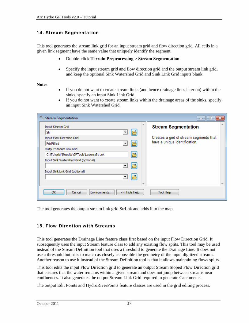
14. Stream Segmentation
This tool generates the stream link grid for an input stream grid and flow direction grid. All cells in a given link segment have the same value that uniquely identify the segment.
Double-click Terrain Preprocessing > Stream Segmentation.
Specify the input stream grid and flow direction grid and the output stream link grid, and keep the optional Sink Watershed Grid and Sink Link Grid inputs blank.
Notes
If you do not want to create stream links (and hence drainage lines later on) within the sinks, specify an input Sink Link Grid.
If you do not want to create stream links within the drainage areas of the sinks, specify an input Sink Watershed Grid.
The tool generates the output stream link grid StrLnk and adds it to the map.
15. Flow Direction with Streams
This tool generates the Drainage Line feature class first based on the input Flow Direction Grid. It subsequently uses the input Stream feature class to add any existing flow splits. This tool may be used instead of the Stream Definition tool that uses a threshold to generate the Drainage Line. It does not use a threshold but tries to match as closely as possible the geometry of the input digitized streams. Another reason to use it instead of the Stream Definition tool is that it allows maintaining flows splits.
This tool edits the input Flow Direction grid to generate an output Stream Sloped Flow Direction grid that ensures that the water remains within a given stream and does not jump between streams near confluences. It also generates the output Stream Link Grid required to generate Catchments.
The output Edit Points and HydroRiverPoints feature classes are used in the grid editing process.

Arc Hydro GP Tools v2.0 – Tutorial
October 2011 38
Note The input Stream feature class must contain a populated HydroID field.
Double-click Attribute Tools > Assign HydroID.
Select NHDFlowline as input feature class and click OK.
The tool creates and populates the HydroID field in the attributed table of NHDFlowline.
Double-click Terrain Preprocessing > Flow Direction with Streams.
Specify FdrFilled as input Flow Direction Grid and NHDFlowline as input Stream.
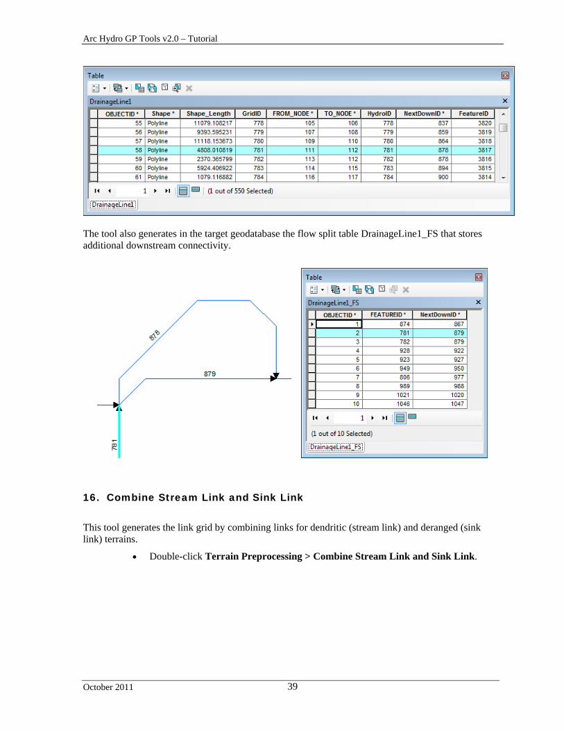
Rename the output StrSlpFdr1, StrLnk1, EditPoints1, HydroRiverPoints1 and DrainageLine1 and click OK.
The 5 outputs are added into the Table of Contents of ArcMap.
Arc Hydro GP Tools v2.0 – Tutorial
October 2011 39
The tool also generates in the target geodatabase the flow split table DrainageLine1_FS that stores additional downstream connectivity.
16. Combine Stream Link and Sink Link
This tool generates the link grid by combining links for dendritic (stream link) and deranged (sink link) terrains.
Double-click Terrain Preprocessing > Combine Stream Link and Sink Link.

Arc Hydro GP Tools v2.0 – Tutorial
October 2011 40
Specify the input Stream Link Grid and Sink Link Grid, as well as the output Link Grid. Click OK.
The tool creates the Sink Link Grid and adds it into the Table of Contents of ArcMap.
17. Catchment Grid Delineation
This tool generates the catchment grid associated to an input flow direction grid and link grid.
Double-click Terrain Preprocessing > Catchment Grid Delineation. Select FdrFilled as input Flow Direction grid and StrLink as input Link Grid. Click
OK.
The tool generates the output catchment grid and adds it to the map.
18. Catchment Polygon Processing
This tool generates the catchment polygon feature classes corresponding to the input catchment grid.
Double-click Terrain Preprocessing > Catchment Polygon Processing.

Arc Hydro GP Tools v2.0 – Tutorial
October 2011 41
Specify the input catchment grid and output catchment polygon feature class. Click OK.
The tool generates the output catchment polygon feature class and adds it to the map.
19. Drainage Line Processing
This tool generates the drainage line feature class associated to an input stream link grid and flow direction grid.
Double-click Terrain Preprocessing > Drainage Line Processing. Select StrLnk as input Stream Link Grid and FdrFilled as input Flow Direction Grid.
Rename the output DrainageLine and click OK.

Arc Hydro GP Tools v2.0 – Tutorial
October 2011 42
The tool generates the output drainage line feature class and adds it to the map.
20. Adjoint Catchment Processing
This tool generates the adjoint catchment polygon feature class associated to an input catchment and drainage line feature classes.
Double-click Terrain Preprocessing > Adjoint Catchment Processing and click OK.
The tool generates the output adjoint catchment polygon feature class and adds it to the map. The field DrainID stores the HydroID of the associated Catchment.
Arc Hydro GP Tools v2.0 – Tutorial
October 2011 43
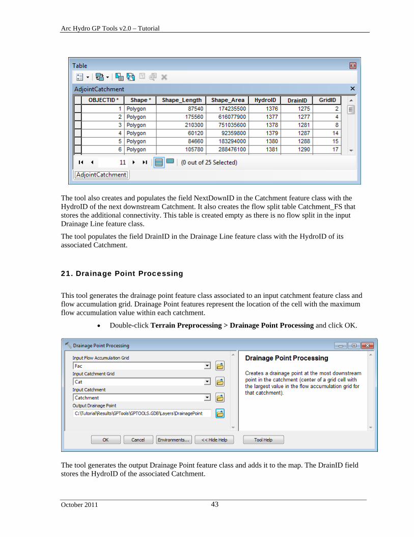
The tool also creates and populates the field NextDownID in the Catchment feature class with the HydroID of the next downstream Catchment. It also creates the flow split table Catchment_FS that stores the additional connectivity. This table is created empty as there is no flow split in the input Drainage Line feature class.
The tool populates the field DrainID in the Drainage Line feature class with the HydroID of its associated Catchment.
21. Drainage Point Processing
This tool generates the drainage point feature class associated to an input catchment feature class and flow accumulation grid. Drainage Point features represent the location of the cell with the maximum flow accumulation value within each catchment.
Double-click Terrain Preprocessing > Drainage Point Processing and click OK.
The tool generates the output Drainage Point feature class and adds it to the map. The DrainID field stores the HydroID of the associated Catchment.

Arc Hydro GP Tools v2.0 – Tutorial
October 2011 44
22. Slope
This tools generates the slope grid in percent or degrees associated to the input DEM. It reads the ZUnit from the projection file defined for the grid and applies the corresponding ZFactor to the elevations in the grid to obtain a slope with the correct units.
Double-click Terrain Preprocessing > Slope and specify the input DEM and the type of measurement for the grid (percent or degree). Keep the default name for the output Slope grid and click OK.
The tool generates the Slope grid for the input DEM.

Arc Hydro GP Tools v2.0 – Tutorial
October 2011 45
23. Depression Evaluation
This tool allows characterizing potential depressions in the input DEMam within that lake.
Double-click Terrain Preprocessing > Depression Evaluation and specify the input DEM. Keep the defaults for the output Depression and Depression Drainage Area feature classes. Click OK.
The tool generates the Depression and Depression Area polygon feature classes.

Arc Hydro GP Tools v2.0 – Tutorial
October 2011 46
24. Adjust Flow Direction in Lakes
This tool allows editing the input Flow Direction Grid within lake features intersecting input streams so that any cell within a lake flows toward the closest stream within that lake.
Double-click Terrain Preprocessing > Adjust Flow Direction in Lakes and specify the input DEM and the type of measurement for the grid (percent or degree). Keep the default name for the output Slope grid and click OK.
Note You can cleanup the temporary folder associated to the tools by using the function ApUtilities > Additional Utilities Clean User’s Temp Folder available on the Arc Hydro Tools toolbar in ArcMap.
Save your map and close your map document.
After closing the map, you may want to manually cleanup any remaining (locked) files in your windows temp location. This location defaults to C:\Documents and Settings\username\Local Settings\Temp.

Arc Hydro GP Tools v 2.0 – Tutorial
October 2011 47
Terrain Preprocessing Workflows The Terrain Preprocessing Workflows toolset contains 4 models as examples of models that string together some of the Terrain Preprocessing tools and allow performing a dendritic terrain preprocessing workflow. It also contains a Batch Processing tool allowing running a model on multiple input data in batch mode.
Note Additional examples of workflows that apply to diverse types of terrains are provided in the document “Comprehensive terrain preprocessing using Arc Hydro tools”.
1. Basic Dendritic Terrain Processing
Open a new map and add the filled DEM grid “filall”grid from the DataGP\Model
folder. Add the Arc Hydro Tools toolbox if needed and save the map as Model.mxd for example.
Right-click Terrain Preprocessing Workflows > Basic Dendritic Terrain
Processing and select Open. The model requires 2 input parameters: a filled DEM and the number of cells defining a stream. This threshold is used in the model to define the stream grid from the flow accumulation grid.
Arc Hydro GP Tools v2.0 – Tutorial
October 2011 48
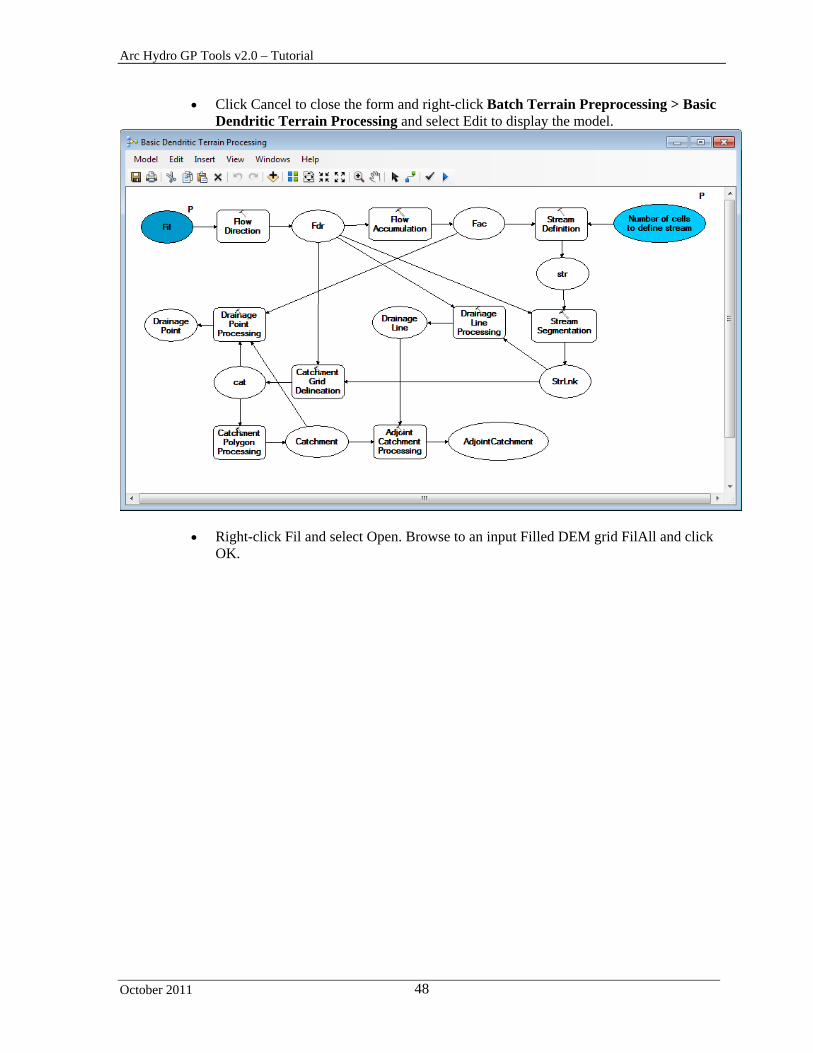
Click Cancel to close the form and right-click Batch Terrain Preprocessing > Basic Dendritic Terrain Processing and select Edit to display the model.
Right-click Fil and select Open. Browse to an input Filled DEM grid FilAll and click OK.
Arc Hydro GP Tools v2.0 – Tutorial
October 2011 49
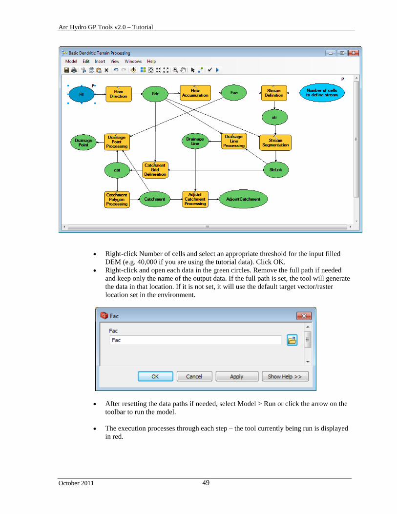
Right-click Number of cells and select an appropriate threshold for the input filled DEM (e.g. 40,000 if you are using the tutorial data). Click OK.
Right-click and open each data in the green circles. Remove the full path if needed and keep only the name of the output data. If the full path is set, the tool will generate the data in that location. If it is not set, it will use the default target vector/raster location set in the environment.
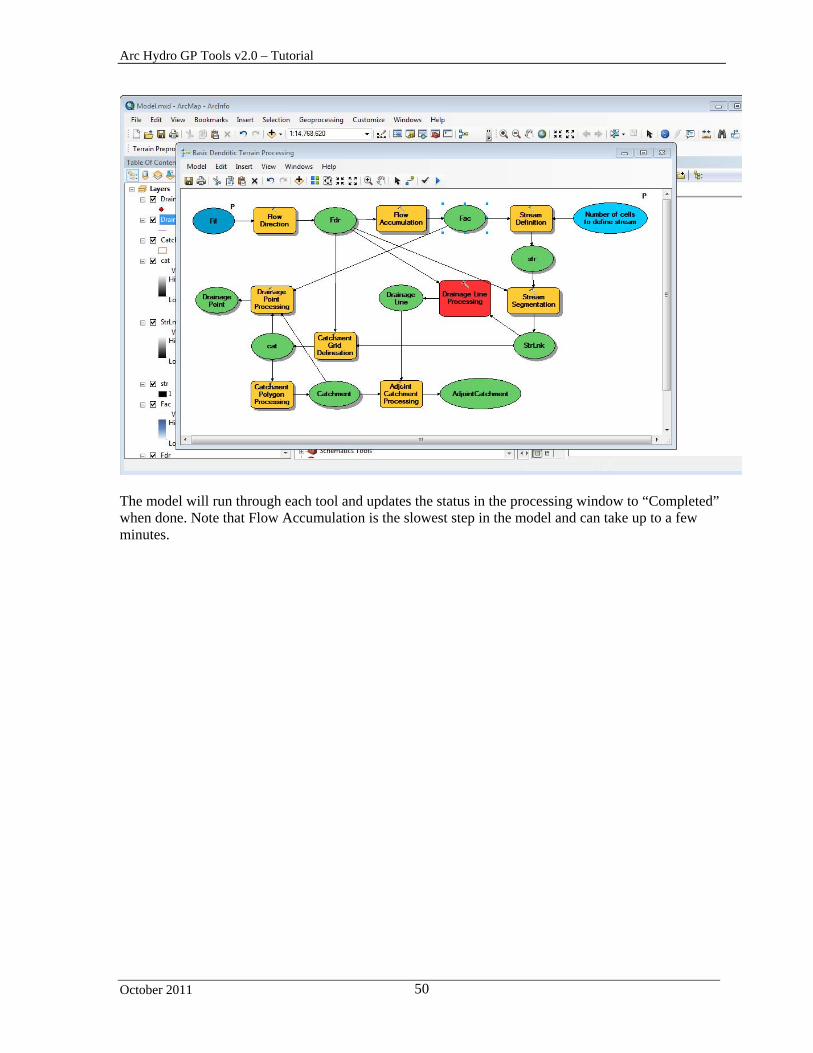
After resetting the data paths if needed, select Model > Run or click the arrow on the toolbar to run the model.
The execution processes through each step – the tool currently being run is displayed
in red.
Arc Hydro GP Tools v2.0 – Tutorial
October 2011 50
The model will run through each tool and updates the status in the processing window to “Completed” when done. Note that Flow Accumulation is the slowest step in the model and can take up to a few minutes.
Arc Hydro GP Tools v2.0 – Tutorial
October 2011 51
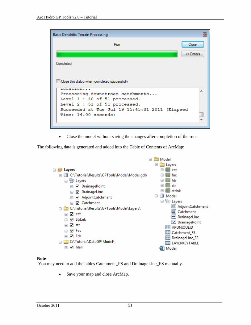
Close the model without saving the changes after completion of the run. The following data is generated and added into the Table of Contents of ArcMap:
Note You may need to add the tables Catchment_FS and DrainageLine_FS manually.
Save your map and close ArcMap.
Arc Hydro GP Tools v2.0 – Tutorial
October 2011 52
2. Batch Processing
The Batch Processing tool allows running a model in batch mode. It will run the model for each subdirectory within the global location specified as input parameter by the user. The batch tool is configured by default to run with the Basic Dendritic Terrain Processing model. You are going to use the tutorial data from the DataGP\Global directory.
Copy the DataGP\Global directory into the location where you want to create your data (e.g. Results\GPTools).
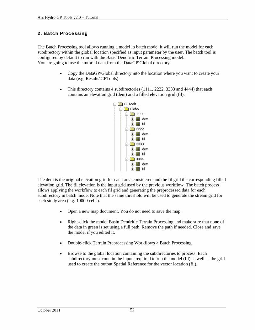
This directory contains 4 subdirectories (1111, 2222, 3333 and 4444) that each
contains an elevation grid (dem) and a filled elevation grid (fil).
The dem is the original elevation grid for each area considered and the fil grid the corresponding filled elevation grid. The fil elevation is the input grid used by the previous workflow. The batch process allows applying the workflow to each fil grid and generating the preprocessed data for each subdirectory in batch mode. Note that the same threshold will be used to generate the stream grid for each study area (e.g. 10000 cells).
Open a new map document. You do not need to save the map.
Right-click the model Basin Dendritic Terrain Processing and make sure that none of the data in green is set using a full path. Remove the path if needed. Close and save the model if you edited it.
Double-click Terrain Preprocessing Workflows > Batch Processing.
Browse to the global location containing the subdirectories to process. Each
subdirectory must contain the inputs required to run the model (fil) as well as the grid used to create the output Spatial Reference for the vector location (fil).

Arc Hydro GP Tools v2.0 – Tutorial
October 2011 53
Keep the default for Input Model and Command Line Arguments but replace 5000 with 10000 for the stream threshold to use. By default, this parameter is set to:
BasicDendriticTerrainProcessing_archydro %RASTERLOCATION%\fil 5000 Where:
BasicDendriticTerrainProcessing_archydro is the name of the model to run %RASTERLOCATION%\fil 10000 are the input parameters required by the model: %RASTERLOCATION% is the raster target location that will be replaced on runtime
with the raster location corresponding to the subdirectory being processed. 5000 is the threshold in number of cells defining the start of a stream.
Notes
Input vector data would be defined using the variable %VECTORLOCATION% that would be replaced on run time with the vector target location for each subdirectory.
Specify the name of the grid used to set the spatial reference for the output vector location (e.g. fil). This grid must exist in each subdirectory.
Click OK to run the tools.
For each subdirectory under the specified global data location:
1. The batch tool first runs the Set Batch Target Locations geoprocessing tool using the name of the specified Grid. You need to have a raster with that name (e.g. Fil) in each subdirectory.
2. The batch tool then runs the specified model. It stores its name in the active configuration in memory under HydroConfig/ProgParams/ApFunctions/ApFunction(BatchTerrainProcessing)/BatchProcessingModelName.
Note The batch tool resets the initial Arc Hydro configuration at the end of the processing.

Arc Hydro GP Tools v2.0 – Tutorial
October 2011 54

Arc Hydro GP Tools v2.0 – Tutorial
October 2011 55
Close the map without saving it.
3. How to create your own model
This section describes how to edit the existing model to create a new model that will require as input a Raw DEM (e.g. elev_cm) and a stream feature class (e.g. NHDFlowline).
Open a new map document and add the Arc Hydro toolbox if needed.
Right-click ArcToolbox and select Add Toolbox. Navigate to the location where you want to store your new toolbox (e.g. Results\GPTools) and then click the New Toolbox icon on the top right of the Add Toolbox window.

Arc Hydro GP Tools v2.0 – Tutorial
October 2011 56
Rename the new toolbox “My Arc Hydro Tools.tbx”. Click Open to add the toolbox into the ArcToolbox window.
Right-click the Basic Dendritic Terrain Processing model and select Copy. Navigate to your new toolbox, right-click and select Paste.

Arc Hydro GP Tools v2.0 – Tutorial
October 2011 57
Right-click the model in your new toolbox and select Properties. Switch to the General tab. Rename this model BasicDendriticTerrainProcessingAgreeFill and label it “Basic Terrain Preprocessing with Reconditioning and Fill”. Click OK.

Arc Hydro GP Tools v2.0 – Tutorial
October 2011 58
Right-click the model and select Edit. Drag the Fill Sinks tool from the Arc Hydro Tools toolbox > Terrain Preprocessing toolset into the model.
Delete the Fil grid input to the Flow Direction tool.
Select the DerangedPoly input to Fill Sinks if visible and delete it as this is an optional output that will not be used. Right-click Fill Sinks and select Open. Set the Fill Threshold to blank, the output to Fil and click OK.

Arc Hydro GP Tools v2.0 – Tutorial
October 2011 59
Click to select and delete the input grid to the Flow Direction tool (e.g. filall).
Right-click Flow Direction, select Open and set the input Hydro DEM to Fil, the output to the Fill Sinks tool.
Save the model, then drag DEM Reconditioning into the model.
Delete the input to the Fill Sinks tool (e.g. DEM). Right-click Fill Sinks and select Open. Set its input grid to Output AGREE DEM.
Right-click RawDEM and AgreeStream and make them Model Parameters.
Arc Hydro GP Tools v2.0 – Tutorial
October 2011 60
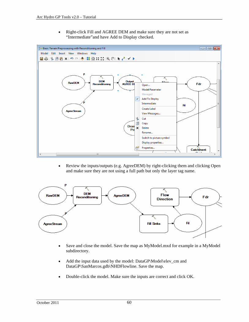
Right-click Fill and AGREE DEM and make sure they are not set as “Intermediate”and have Add to Display checked.
Review the inputs/outputs (e.g. AgreeDEM) by right-clicking them and clicking Open and make sure they are not using a full path but only the layer tag name.
Save and close the model. Save the map as MyModel.mxd for example in a MyModel subdirectory.
Add the input data used by the model: DataGP\Model\elev_cm and
DataGP\SanMarcos.gdb\NHDFlowline. Save the map.
Double-click the model. Make sure the inputs are correct and click OK.

Arc Hydro GP Tools v2.0 – Tutorial
October 2011 61
The outputs from the model are generated and added into the Table of Contents of ArcMap.
Arc Hydro GP Tools v2.0 – Tutorial
October 2011 62
Save the map and close ArcMap.
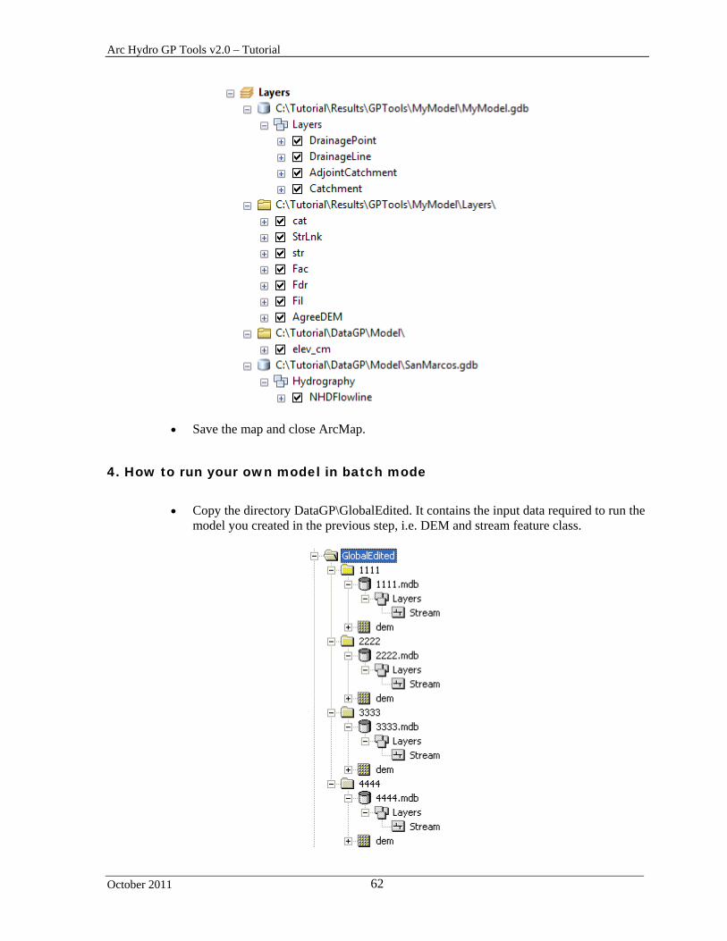
4. How to run your own model in batch mode
Copy the directory DataGP\GlobalEdited. It contains the input data required to run the
model you created in the previous step, i.e. DEM and stream feature class.

Arc Hydro GP Tools v2.0 – Tutorial
October 2011 63
Open a new map document. You do not need to save the map.
If you do not see the model you previously created, you need to add it to the ArcToolbox window.
Right-click ArcToolbox and select Add Toolbox. Browse to the location where you have saved the new toolbox and open My Arc Hydro Tools.tbx.
The Batch Processing tool requires 3 inputs:
- Input Global Data Location: parent directory containing the subdirectories to process (GlobalEdited)
- Input Model and Command Line Arguments – needs to be updated to reflect the new model/arguments
- Input Name of Grid use to set the output Spatial Reference – same as previously
1. The batch tool first runs the Set Batch Target Locations geoprocessing tools using the input name
of the grid specified. You need to have a raster with that name in each subdirectory under your global data location.
2. The batch tool then runs the model specified.
The batch tool retrieves the name of the grid used to setup the spatial reference in the subdirectories and the name and parameters of the model from the specified parameters. Default values are read from the active configuration in the ArcMap or ArcCatalog session.
The batch tool retrieves the parameters for the tools used in the model based on the active Arc Hydro configuration.
The name and parameter(s) of the model run by the Batch Dendritic Terrain Preprocessing tool is defined in the configuration as well. You can modify the configuration so that the batch tool calls your own model.
Open the Python window in ArcMap or ArcCatalog and paste the following to see the usage for your model:
print arcpy.Usage("BasicDendriticTerrainProcessingAgreeFill")
The following text is displayed:

Arc Hydro GP Tools v2.0 – Tutorial
October 2011 64
The default BatchProcessingModelName is set to:
BasicDendriticTerrainProcessing_archydro %RASTERLOCATION%\fil 5000
Set it to your own model and make sure the parameters are listed in the correct order. BasicDendriticTerrainProcessingAgreeFill 10000 %RASTERLOCATION%\dem %VECTORLOCATION%\Layers\Stream
Note that this means that a raster named dem and a feature class called Stream MUST exist in each subdirectory being processed or the model will fail for that directory.
Browse to the global location containing the subdirectories to process (e.g. GlobalEdited). Each subdirectory must contain the inputs required to run the model as well as the grid used to setup the spatial reference for the vector locations.
Set dem as input grid used to set the output spatial reference. Note that in this case the
output locations already exist.
Click OK to run the Batch Processing tool.

Arc Hydro GP Tools v2.0 – Tutorial
October 2011 65
The Batch tool creates the outputs in each subdirectory.
Close the map.

Arc Hydro GP Tools v2.0 – Tutorial
October 2011 66
Network Tools This section walks you through the Network Tools in the geoprocessing environment. Note that each tool has a corresponding function in the standard Arc Hydro tools toolbar.
You are going to use the data from DataGP\SanMarcos\SanMarcos.mdb in this section: Catchment, Drainage Line and DrainagePoint.
Copy the geodatabase DataGP\Networkfolder\SanMarcos.mdb into your target directory (e.g. Results\GPTools\Network).
1. Hydro Network Generation
Open a new map and add the DrainageLine, DrainagePoint and Catchment features
classes from the copied DataGP\Network\SanMarcos.gdb geodatabase. Save the map as Network.mxd.
Reset the target location to the Network folder and the SanMarcos.mdb geodatabase
by using the Arc Hydro Setup > Set Target Locations tool.
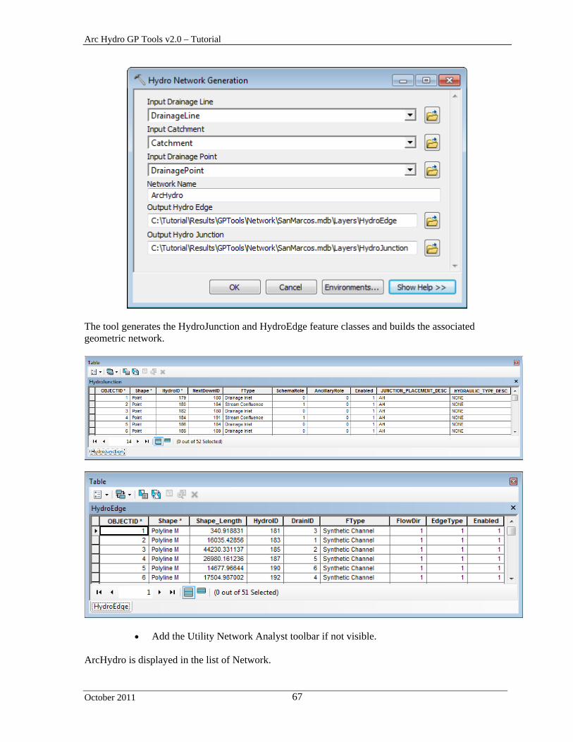
Double-click Network Tools > Hydro Network Generation. Select DrainageLine, Catchment and DrainagePoint respectively as input. Keep the default names for the output Network Name, Hydro Edge and Hydro Junction and click OK.
Arc Hydro GP Tools v2.0 – Tutorial
October 2011 67
The tool generates the HydroJunction and HydroEdge feature classes and builds the associated geometric network.
Add the Utility Network Analyst toolbar if not visible. ArcHydro is displayed in the list of Network.
Arc Hydro GP Tools v2.0 – Tutorial
October 2011 68
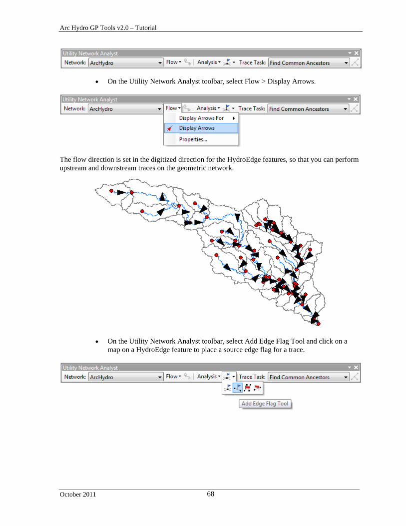
On the Utility Network Analyst toolbar, select Flow > Display Arrows.
The flow direction is set in the digitized direction for the HydroEdge features, so that you can perform upstream and downstream traces on the geometric network.
On the Utility Network Analyst toolbar, select Add Edge Flag Tool and click on a map on a HydroEdge feature to place a source edge flag for a trace.
Arc Hydro GP Tools v2.0 – Tutorial
October 2011 69
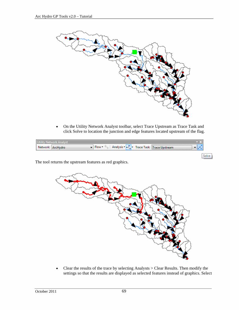
On the Utility Network Analyst toolbar, select Trace Upstream as Trace Task and click Solve to location the junction and edge features located upstream of the flag.
The tool returns the upstream features as red graphics.
Clear the results of the trace by selecting Analysts > Clear Results. Then modify the settings so that the results are displayed as selected features instead of graphics. Select

Arc Hydro GP Tools v2.0 – Tutorial
October 2011 70
Analysis > Options… and in the Results tab check Selection instead of Drawings and click OK.
Click Solve to perform the upstream trace again. This time the upstream features are selected.
Arc Hydro GP Tools v2.0 – Tutorial
October 2011 71
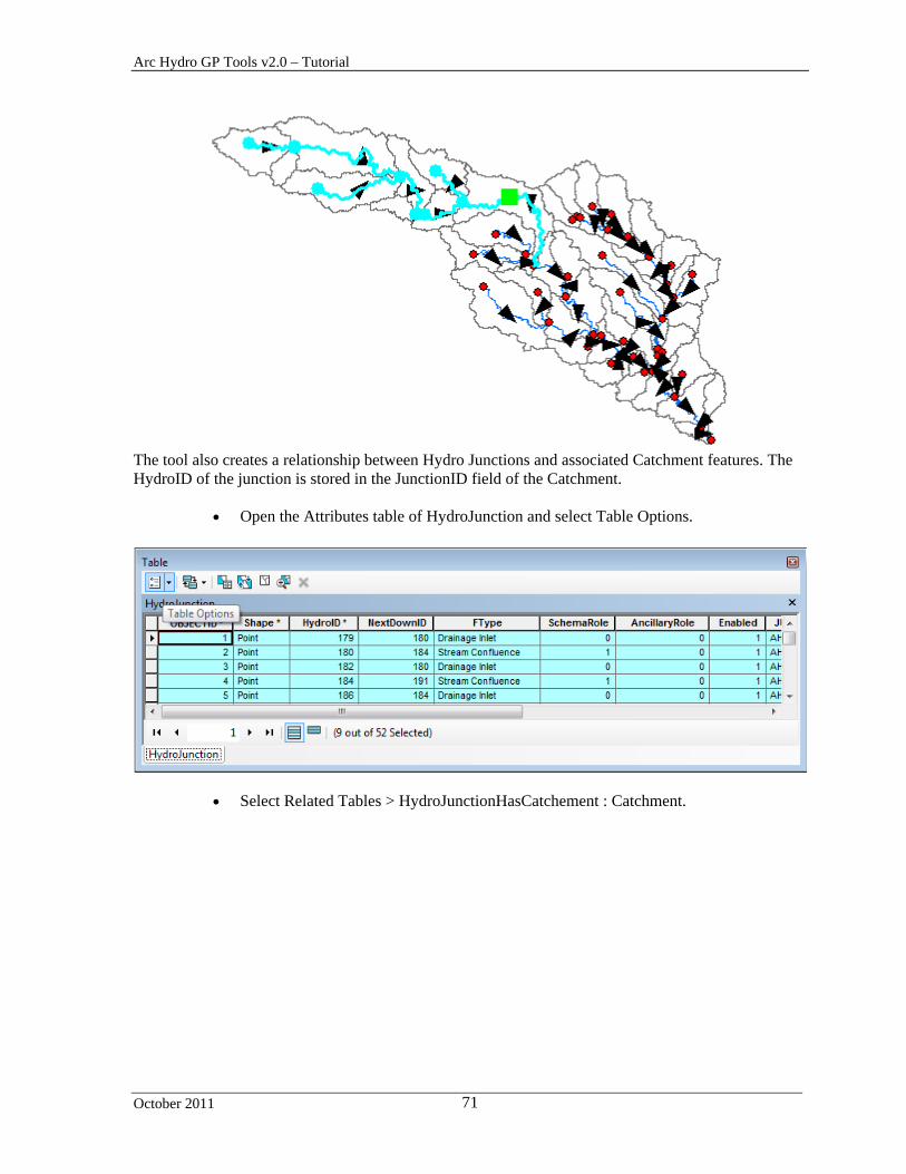
The tool also creates a relationship between Hydro Junctions and associated Catchment features. The HydroID of the junction is stored in the JunctionID field of the Catchment.
Open the Attributes table of HydroJunction and select Table Options.
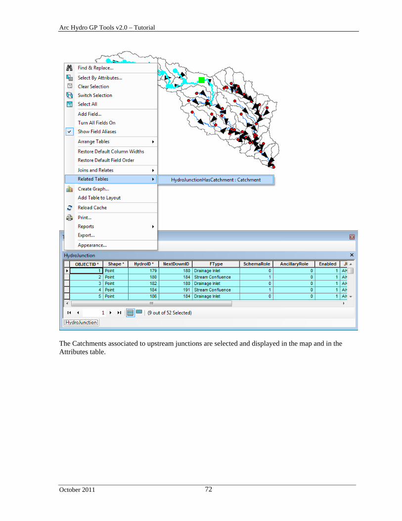
Select Related Tables > HydroJunctionHasCatchement : Catchment.
Arc Hydro GP Tools v2.0 – Tutorial
October 2011 72
The Catchments associated to upstream junctions are selected and displayed in the map and in the Attributes table.
Arc Hydro GP Tools v2.0 – Tutorial
October 2011 73
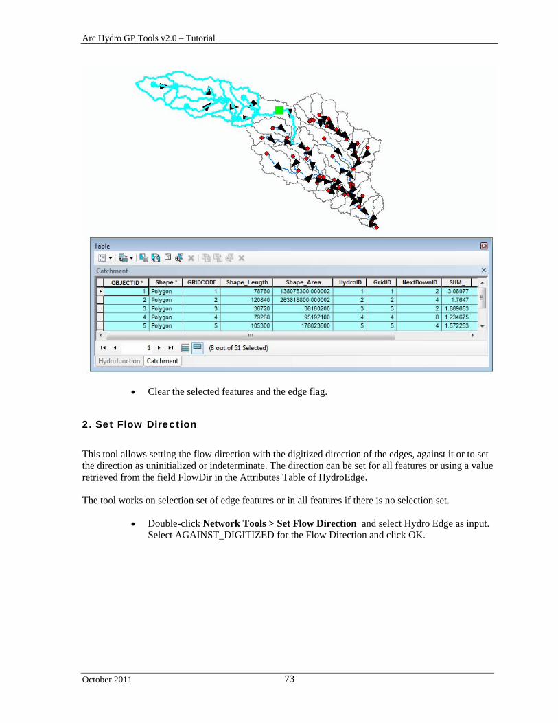
Clear the selected features and the edge flag.
2. Set Flow Direction
This tool allows setting the flow direction with the digitized direction of the edges, against it or to set the direction as uninitialized or indeterminate. The direction can be set for all features or using a value retrieved from the field FlowDir in the Attributes Table of HydroEdge. The tool works on selection set of edge features or in all features if there is no selection set.
Double-click Network Tools > Set Flow Direction and select Hydro Edge as input. Select AGAINST_DIGITIZED for the Flow Direction and click OK.

Arc Hydro GP Tools v2.0 – Tutorial
October 2011 74
The tool switches the direction of the edges in the geometric network. Note that the arrows are now pointing in the opposite (upstream) direction.
Arc Hydro GP Tools v2.0 – Tutorial
October 2011 75
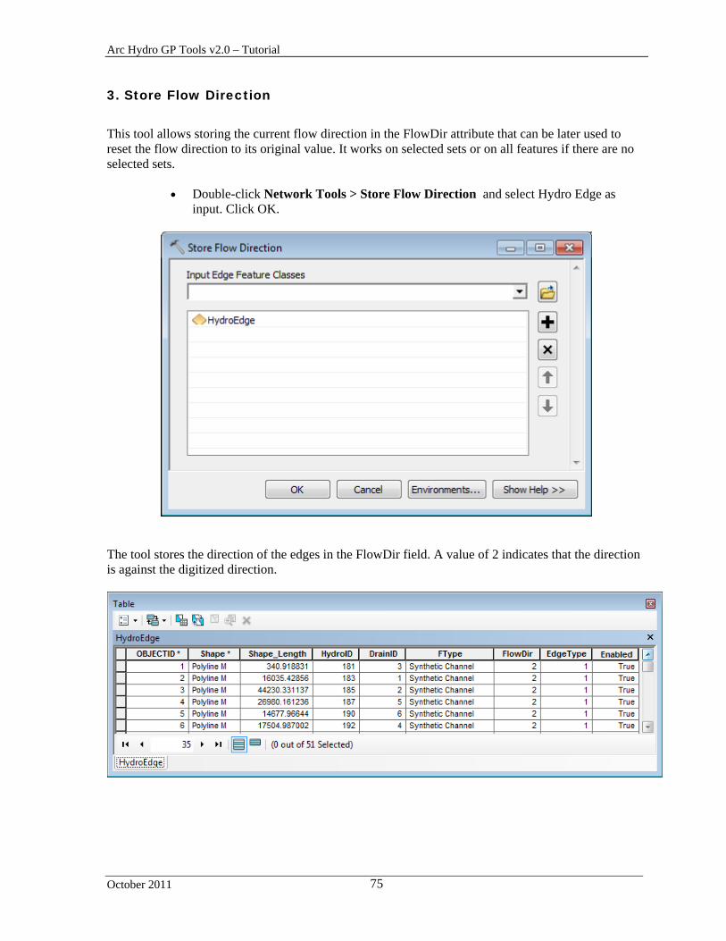
3. Store Flow Direction
This tool allows storing the current flow direction in the FlowDir attribute that can be later used to reset the flow direction to its original value. It works on selected sets or on all features if there are no selected sets.
Double-click Network Tools > Store Flow Direction and select Hydro Edge as input. Click OK.
The tool stores the direction of the edges in the FlowDir field. A value of 2 indicates that the direction is against the digitized direction.
Arc Hydro GP Tools v2.0 – Tutorial
October 2011 76
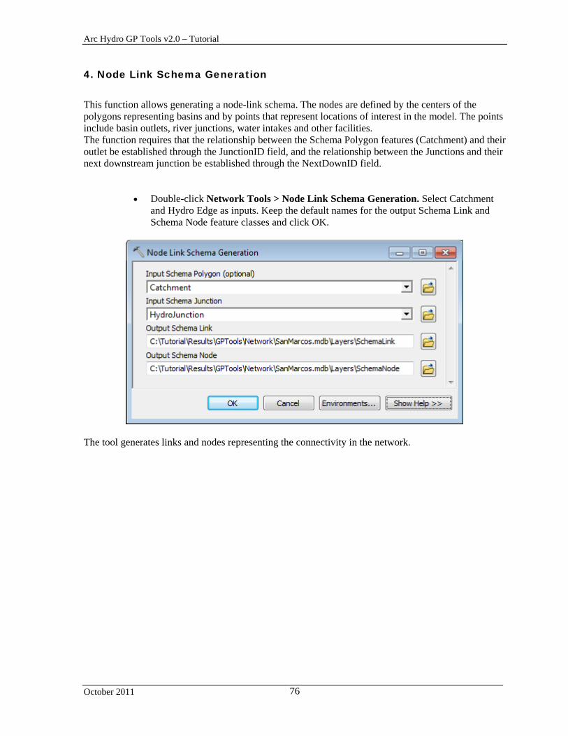
4. Node Link Schema Generation
This function allows generating a node-link schema. The nodes are defined by the centers of the polygons representing basins and by points that represent locations of interest in the model. The points include basin outlets, river junctions, water intakes and other facilities. The function requires that the relationship between the Schema Polygon features (Catchment) and their outlet be established through the JunctionID field, and the relationship between the Junctions and their next downstream junction be established through the NextDownID field.
Double-click Network Tools > Node Link Schema Generation. Select Catchment and Hydro Edge as inputs. Keep the default names for the output Schema Link and Schema Node feature classes and click OK.
The tool generates links and nodes representing the connectivity in the network.

Arc Hydro GP Tools v2.0 – Tutorial
October 2011 77
Save the map document and close then map.

Arc Hydro GP Tools v2.0 – Tutorial
October 2011 78
Attribute Tools These tools allow populating attributes in the specified tables or feature classes.
You will use the data from the DataGP\ModelResult folder to test these tools.
Copy this data directory into a new location since you will be editing the data.
Open a new map document and add the Drainage Line feature class into the Table of Contents of ArcMap. Save the map as AttributesTools.mxd for example.
In this example, you are going to use the existing database (Model.mdb) as vector target location.
Double-click the Set Target Locations tool and browse to the existing target locations. Click OK.
Arc Hydro GP Tools v2.0 – Tutorial
October 2011 79
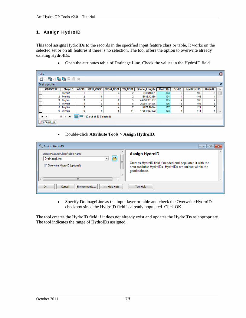
1. Assign HydroID
This tool assigns HydroIDs to the records in the specified input feature class or table. It works on the selected set or on all features if there is no selection. The tool offers the option to overwrite already existing HydroIDs.
Open the attributes table of Drainage Line. Check the values in the HydroID field.
Double-click Attribute Tools > Assign HydroID.
Specify DrainageLine as the input layer or table and check the Overwrite HydroID checkbox since the HydroID field is already populated. Click OK.
The tool creates the HydroID field if it does not already exist and updates the HydroIDs as appropriate. The tool indicates the range of HydroIDs assigned.

Arc Hydro GP Tools v2.0 – Tutorial
October 2011 80
Note If the HydroIDs are being overwritten while the table is opened in ArcMap, the table needs to be closed and reopened to view the updated HydroIDs.
2. Assign UniqueID
This tool assigns unique identifiers to the field specified by the user. The tool works on a selected set or on all features if there is no existing selection. The tool offers the option to overwrite already existing IDs.
Double-click Attribute Tools > Assign UniqueID.
Specify DrainageLine as the input layer or table, HydroID as UniqueID field and check the Overwrite HydroID checkbox since the HydroID field is already populated. Click OK.

Arc Hydro GP Tools v2.0 – Tutorial
October 2011 81
The tool populates the selected UniqueID field (HydroID).
3. Generate From/To Node for Lines
This tool stores the connectivity between line features by creating and populating the fields From_Node and To_Node.
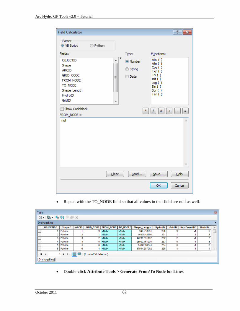
Open the Attributes table of DrainageLine, right-click the FROM_NODE field and select Field Calculator… Enter null in the Field Calculator form and click OK to reset the values to null.
Arc Hydro GP Tools v2.0 – Tutorial
October 2011 82
Repeat with the TO_NODE field so that all values in that field are null as well.
Double-click Attribute Tools > Generate From/To Node for Lines.

Arc Hydro GP Tools v2.0 – Tutorial
October 2011 83
Specify DrainageLine as input Line feature layer for which you want to populate the From_Node/To_Node fields and click OK.
The tool populates the fields FROM_NODE and TO_NODE in the input Line feature class.
4. Find Next Downstream Line
This tool finds the next downstream line based on the From_Node and To_Node fields populated with the previous tool, Generate From/To Node for Lines. It creates the NextDownID field if it does not already exist and populates this field with the HydroID of the next downstream line. The tool also

Arc Hydro GP Tools v2.0 – Tutorial
October 2011 84
creates a flow split table named by appending _FS to the name of the input Line feature class. This table stores the additional connectivity information for cases when flow splits occur and there is more than one downstream line.
Updating the HydroIDs in Drainage Line with the Assign Hydro tool results in incorrect values being stored in the NextDownID field. NextDownIDs are supposed to represent the HydroIDs of the next downstream lines. These values need to be updated to match the new HydroIDs by using the Find Next Downstream Line tool.
Double-click Attribute Tools > Find Next Downstream Line.
Specify Drainage Line as the input Line feature class for which you want to populate NextDownIDs and click OK.
The tool creates the NextDownID field if it does not already exist and populates it with the HydroID of the next downstream line feature.
Note If the input Line feature class contains flow splits, the additional connectivity information is stored in the flow split table named by appending the suffix “_FS” to the name of the Line feature class (e.g. DrainageLine_FS). The table will be empty if there is no flow splits.

Arc Hydro GP Tools v2.0 – Tutorial
October 2011 85
5. Find Next Downstream Junction
This tool works on a geometric network junction feature class. You are first going to create a geometric network using Hydro Network Generation tool.
Add the Catchment and Drainage Point feature class into the map.
Double-click Network Tools > Hydro Network Generation. Keep the default inputs/outputs and click OK to generate the network.
The tool generates the HydroJunction junction feature class that participates in the geometric network.
Double-click Attribute Tools > Find Next Downstream Junction. Specify HydroJunction as input Junction feature class and click OK.

Arc Hydro GP Tools v2.0 – Tutorial
October 2011 86
The tool identifies the next downstream junction in the network and populates the field NextDownID with the HydroID of the next junction feature.
6. Calculate Length Downstream for Edges
This tool allows calculating the length downstream for edges in a geometric network.
Double-click Attribute Tools > Calculate Length Downstream for Edges and select HydroEdge as input Edge Feature Classes. Click OK.
The tool creates and populates the field LENGHTDOWN for each input edge processed.

Arc Hydro GP Tools v2.0 – Tutorial
October 2011 87
7. Calculate Length Downstream for Junctions
This tool allows calculating the length downstream for junctions in a geometric network.
Double-click Attribute Tools > Calculate Length Downstream for Junctions.
The tool creates and populates the field LENGHTDOWN for each input junction processed.

Arc Hydro GP Tools v2.0 – Tutorial
October 2011 88
8. Store Area Outlets by Drainage Point Proximity
Double-click Attribute Tools > Store Area Outlets by Drainage Point Proximity.
9. Store Area Outlets by Junction Intersect
Double-click Attribute Tools > Store Area Outlets by Junction Intersect.
10. Store Area Outlets by Next Downstream Area
Double-click Attribute Tools > Store Area Outlets by Next Downstream Area.

Arc Hydro GP Tools v2.0 – Tutorial
October 2011 89
11. Compute Global Parameters
This tool computes the specified characteristics for selected watershed features. It is setup to work for a global environment. The tool identifies the location of the data required to characterize each selected watershed by using a cataloging unit layer with the Name field. This global tool can also be used in a standard “local” environment by setting up a cataloging unit polygon feature class with one feature covering the extent of the data. This allows the data to reside on the disk instead of having to add it into the map (when using the tool in ArcMap) and also allows the tool to be used in ArcCatalog since it does not depend on the map. You are going to setup the tool to work with your local data.
Double-click Attribute Tools > Compute Global Parameters.

Arc Hydro GP Tools v2.0 – Tutorial
October 2011 90
The tool requires as input the Global Watershed feature class that needs to be characterized and the cataloging unit polygon that allows identifying the location of the supporting data on the disk. The Global Data Path must be set to the location of the parent directory under which the supporting data directory is located. The name of the subdirectory is read from the Name field in the Cataloging Unit Polygon feature class.
You are going to characterize the Catchment features corresponding to the Drainage Line features in the map.
Click Cancel to close the tool and open the Attributes table of Catchment.
The supporting data for this example is located in the directory DataGP\GlobalParams.
Browse to the Global.gdb database in this location and add the Cataloging Unit Polygon layer HUCPoly into the Table of Contents of ArcMap.
Arc Hydro GP Tools v2.0 – Tutorial
October 2011 91
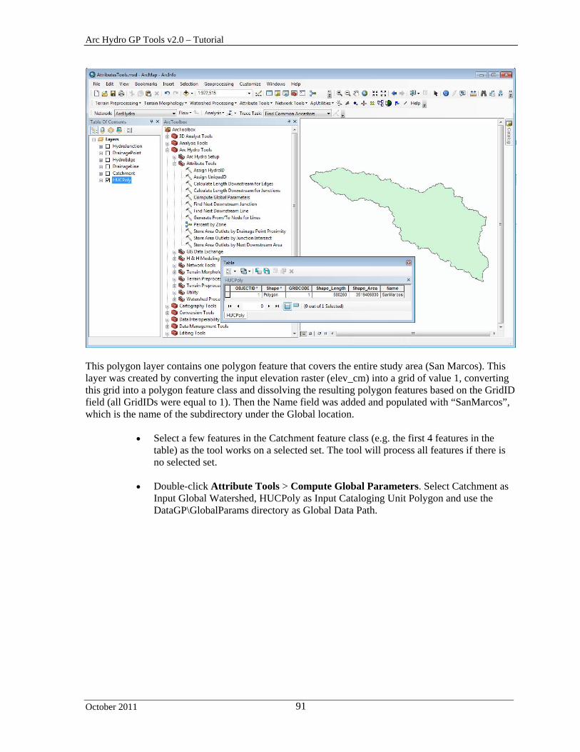
This polygon layer contains one polygon feature that covers the entire study area (San Marcos). This layer was created by converting the input elevation raster (elev_cm) into a grid of value 1, converting this grid into a polygon feature class and dissolving the resulting polygon features based on the GridID field (all GridIDs were equal to 1). Then the Name field was added and populated with “SanMarcos”, which is the name of the subdirectory under the Global location.
Select a few features in the Catchment feature class (e.g. the first 4 features in the table) as the tool works on a selected set. The tool will process all features if there is no selected set.
Double-click Attribute Tools > Compute Global Parameters. Select Catchment as
Input Global Watershed, HUCPoly as Input Cataloging Unit Polygon and use the DataGP\GlobalParams directory as Global Data Path.

Arc Hydro GP Tools v2.0 – Tutorial
October 2011 92
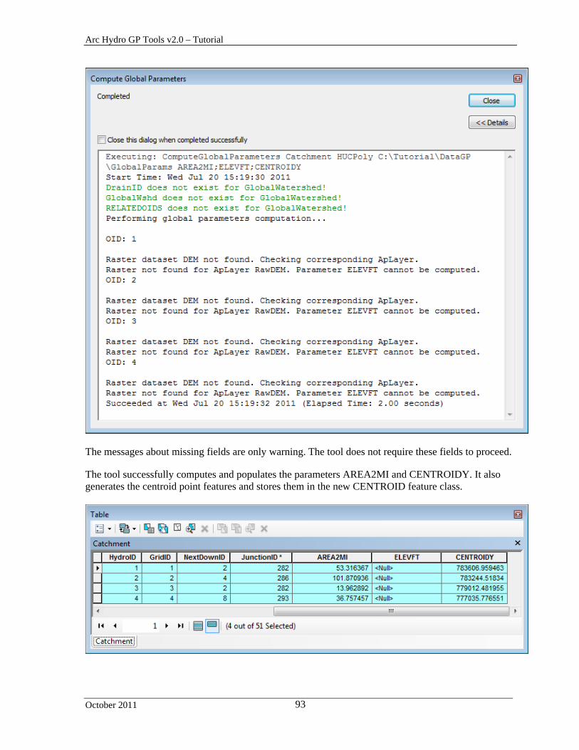
Select AREA2MI, ELEVFT and CENTROIDY as Input Parameters and click OK. The tool fails with the following messages:
Arc Hydro GP Tools v2.0 – Tutorial
October 2011 93
The messages about missing fields are only warning. The tool does not require these fields to proceed. The tool successfully computes and populates the parameters AREA2MI and CENTROIDY. It also generates the centroid point features and stores them in the new CENTROID feature class.

Arc Hydro GP Tools v2.0 – Tutorial
October 2011 94
The parameter ELEVFT is not computed. The following message is displayed for each feature:
OID: 1 Raster dataset DEM not found. Checking corresponding ApLayer.
Raster not found for ApLayer RawDEM. Parameter ELEVFT cannot be computed.
The computation failed because the function could not find the input elevation grid DEM in the input directory. The name of the elevation grid needs to be set to elev_cm instead of DEM in the XML configuration associated to the map.
Select ApUtilities > XML Manager to open the active configuration.
Browse to the node
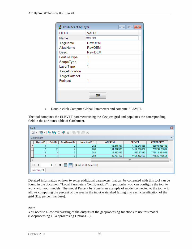
HydroConfig\ProgParams\ApFunctions\ApFunction(WshParams)\ApFields\ApField(ELEVFT)\ApLayers\ApLayer(RawDEM,DEM). Right-click this node and select EditAttributes. Change Name from DEM to elev_cm and click OK. Close the form and save the map.
Arc Hydro GP Tools v2.0 – Tutorial
October 2011 95
Double-click Compute Global Parameters and compute ELEVFT.
The tool computes the ELEVFT parameter using the elev_cm grid and populates the corresponding field in the attributes table of Catchment.
Detailed information on how to setup additional parameters that can be computed with this tool can be found in the document “Local Parameters Configuration”. In particular, you can configure the tool to work with your models. The model Percent by Zone is an example of model connected to the tool – it allows computing the percent of the area in the input watershed falling into each classification of the grid (E.g. percent landuse).
Note You need to allow overwriting of the outputs of the geoprocessing functions to use this model (Geoprocessing > Geoprocessing Options…).

Arc Hydro GP Tools v2.0 – Tutorial
October 2011 96
Double-click Compute Global Parameters and compute the parameter LUSE_NLCD.
The tool computes predefined landuse percentages and store their values in new fields created in the attributes table of Catchment.
Save and close the map.
Arc Hydro GP Tools v2.0 – Tutorial
October 2011 97
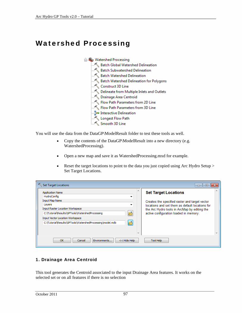
Watershed Processing
You will use the data from the DataGP\ModelResult folder to test these tools as well.
Copy the contents of the DataGP\ModelResult into a new directory (e.g. WatershedProcessing).
Open a new map and save it as WatershedProcessing.mxd for example.
Reset the target locations to point to the data you just copied using Arc Hydro Setup >
Set Target Locations.
1. Drainage Area Centroid
This tool generates the Centroid associated to the input Drainage Area features. It works on the selected set or on all features if there is no selection
Arc Hydro GP Tools v2.0 – Tutorial
October 2011 98
Add the Catchment feature class into the map.
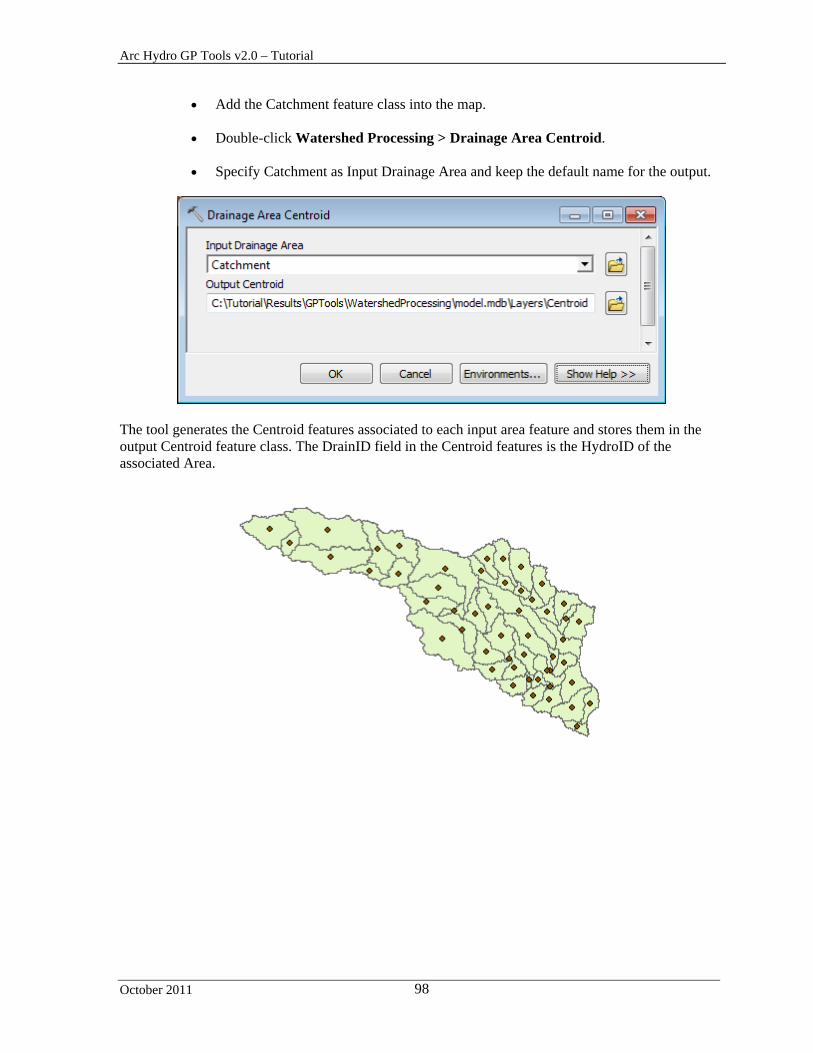
Double-click Watershed Processing > Drainage Area Centroid.
Specify Catchment as Input Drainage Area and keep the default name for the output.
The tool generates the Centroid features associated to each input area feature and stores them in the output Centroid feature class. The DrainID field in the Centroid features is the HydroID of the associated Area.

Arc Hydro GP Tools v2.0 – Tutorial
October 2011 99
2. Longest Flow Path
This tool generates the Longest Flow Path associated to the input Drainage Area features. It works on the selected set or on all features if there is no selection
Add the flow direction grid (fdr) into the map.
Double-click Watershed Processing > Longest Flow Path.
Specify Catchment as Input Drainage Area, fdr as Input Flow Direction Grid and keep
the default name for the output. Click OK.
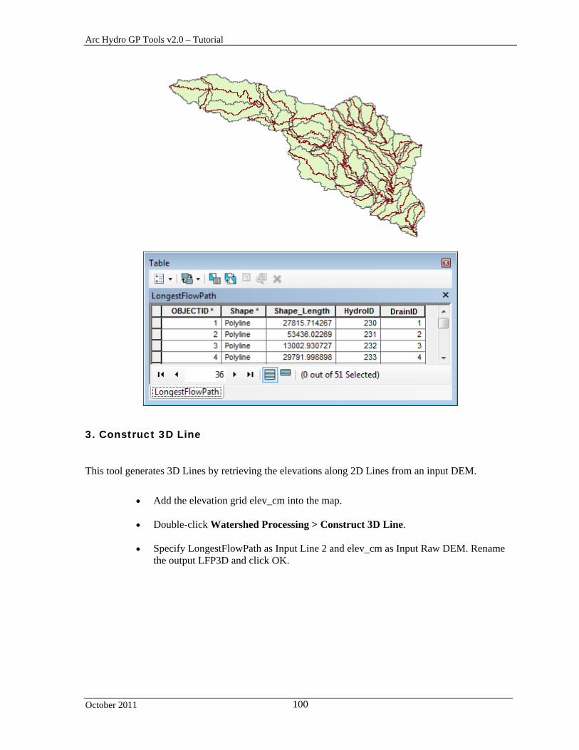
The tool generates the Longest Flow Path features associated to each input area feature and stores them in the output LongestFlowPath feature class.
Arc Hydro GP Tools v2.0 – Tutorial
October 2011 100
3. Construct 3D Line
This tool generates 3D Lines by retrieving the elevations along 2D Lines from an input DEM.
Add the elevation grid elev_cm into the map.
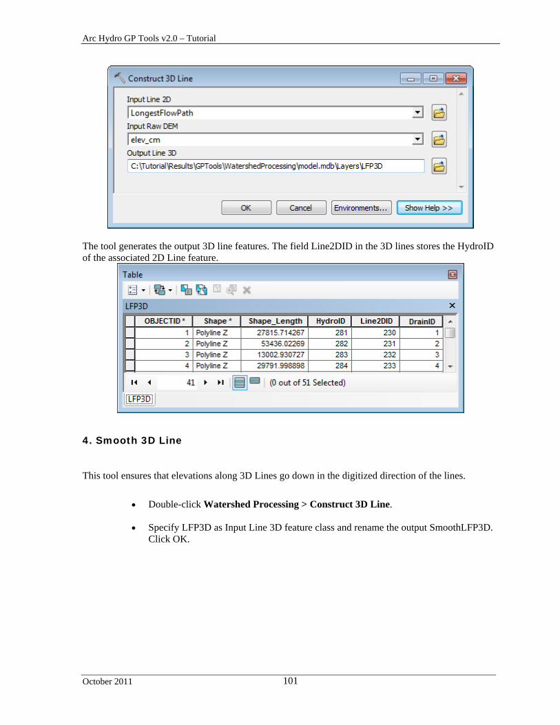
Double-click Watershed Processing > Construct 3D Line.
Specify LongestFlowPath as Input Line 2 and elev_cm as Input Raw DEM. Rename
the output LFP3D and click OK.
Arc Hydro GP Tools v2.0 – Tutorial
October 2011 101
The tool generates the output 3D line features. The field Line2DID in the 3D lines stores the HydroID of the associated 2D Line feature.
4. Smooth 3D Line
This tool ensures that elevations along 3D Lines go down in the digitized direction of the lines.
Double-click Watershed Processing > Construct 3D Line.
Specify LFP3D as Input Line 3D feature class and rename the output SmoothLFP3D.
Click OK.

Arc Hydro GP Tools v2.0 – Tutorial
October 2011 102
The tool edits the elevations along each line so that the elevations go down along the digitized direction of the features.
The field Line3DID stores the HydroID of the input 3D Line associated to the smoothed line.
5. Flow Path Parameters from 2D Line
This tool computes slope, length and elevation parameters for 2D longest flow path lines by extracting elevations from an input DEM.

Arc Hydro GP Tools v2.0 – Tutorial
October 2011 103
Double-click Watershed Processing > Flow Path Parameters from 2D Line.
Specify LongestFlowPath as Input Longest Flow Path and elev_cm as input Raw
DEM. Keep the default name for the output Slp1085Point feature class and click OK.
The tool computes the Length of the line in miles, its slope in Feet per mile and the dimensionless slope, its slope 10-85 in miles and dimensionless, and the elevation at its from point, to point and at the points located at 10% and 85% of the length along the line starting from the downstream end.
The tool generates the 10-85 points associated to the lines and stores their elevation. The DrainID field stores the HydroID of the Drainage Area (e.g. Catchment) associated to the input line.
Arc Hydro GP Tools v2.0 – Tutorial
October 2011 104
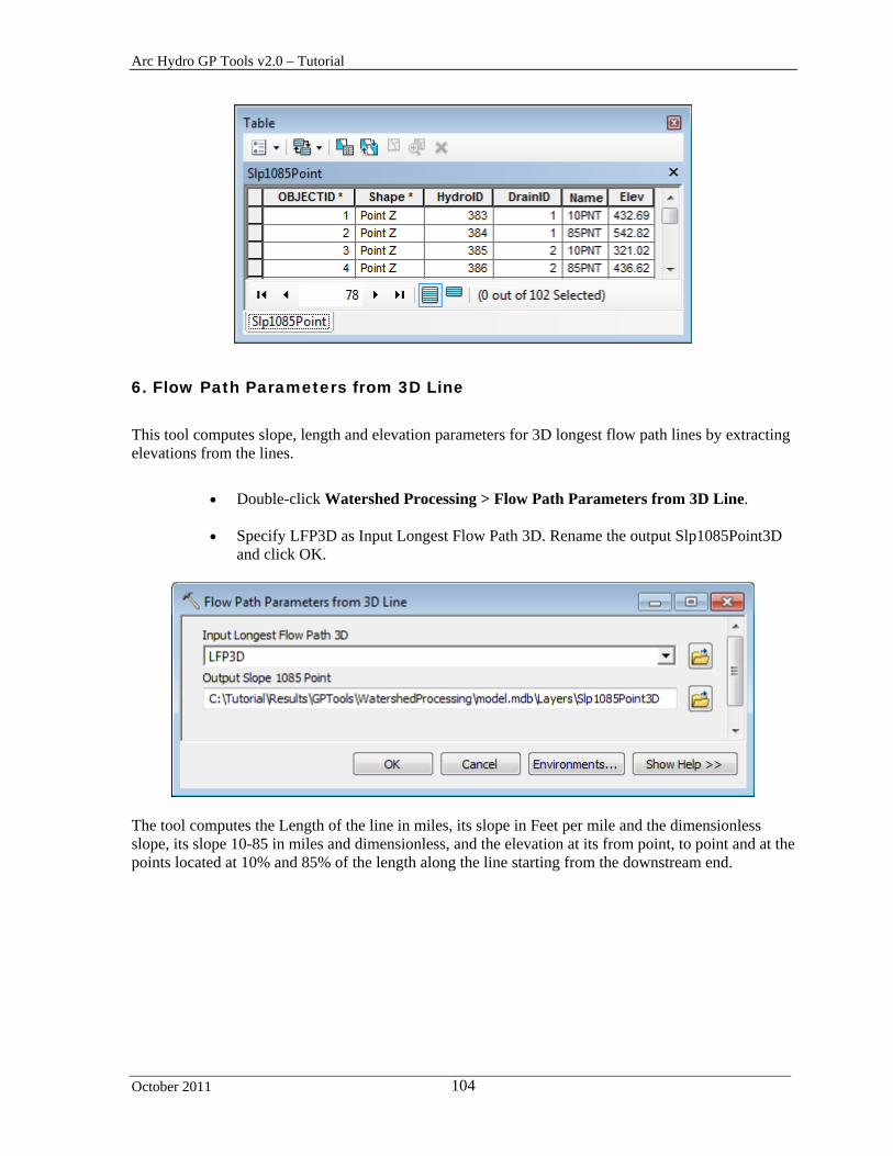
6. Flow Path Parameters from 3D Line
This tool computes slope, length and elevation parameters for 3D longest flow path lines by extracting elevations from the lines.
Double-click Watershed Processing > Flow Path Parameters from 3D Line.
Specify LFP3D as Input Longest Flow Path 3D. Rename the output Slp1085Point3D
and click OK.
The tool computes the Length of the line in miles, its slope in Feet per mile and the dimensionless slope, its slope 10-85 in miles and dimensionless, and the elevation at its from point, to point and at the points located at 10% and 85% of the length along the line starting from the downstream end.

Arc Hydro GP Tools v2.0 – Tutorial
October 2011 105
The tool generates the 10-85 points associated to the lines and stores their elevation. The DrainID field stores the HydroID of the Drainage Area (e.g. Catchment) associated to the input line.
7. Batch Watershed Delineation
This tool allows performing batch watershed delineations based on an input Batch Point feature class.
Add the AdjointCatchment feature class and str grid into the map. You first need to create the Batch Point feature class and add a few points to delineate.
On the Arc Hydro Tools toolbar, click the Batch Point Generation tool ( ) and specify Batch Point as Batch Point feature class. Click OK.

Arc Hydro GP Tools v2.0 – Tutorial
October 2011 106
Click on the map at the location where you want to create the first point to delineate and enter the name and description of the point and whether to snap it (1 – snap, 0 – do not snap). Click OK to create the point.
Click again on the map to create a second point.

Arc Hydro GP Tools v2.0 – Tutorial
October 2011 107
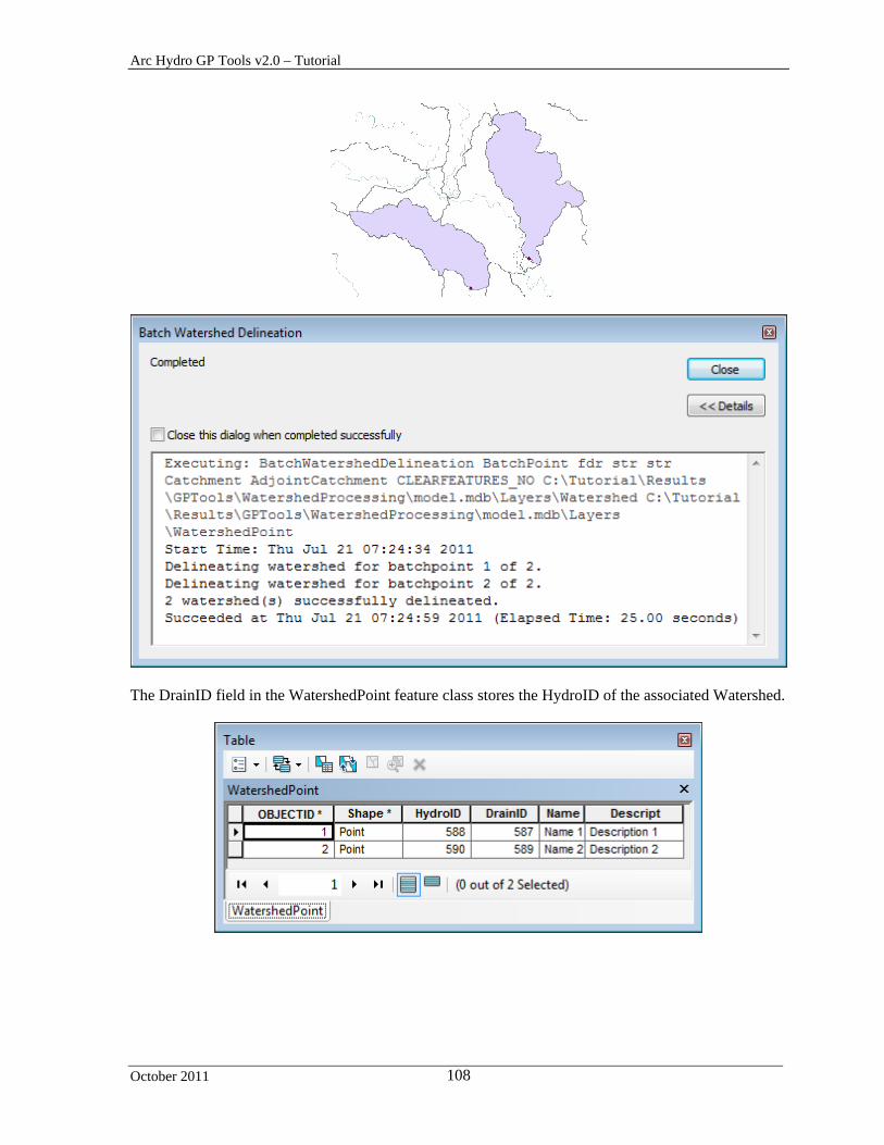
Double-click Watershed Processing > Batch Watershed Delineation.
Select the inputs/outputs as shown below and click OK to perform the delineations.
The tool delineates watersheds for the input batch point features.
Arc Hydro GP Tools v2.0 – Tutorial
October 2011 108
The DrainID field in the WatershedPoint feature class stores the HydroID of the associated Watershed.

Arc Hydro GP Tools v2.0 – Tutorial
October 2011 109
8. Interactive Delineation
This model allows performing one or many watershed delineation associated to the input points provided by clicking from the map or by using an input point feature class. It uses the Batch Watershed Delineation tool.
Right-click the model Interactive Delineation and select Edit.

Arc Hydro GP Tools v2.0 – Tutorial
October 2011 110
Close the model.
Double-click Watershed Processing > Interactive Delineation.
Select fdr, str, Catchment, AdjointCatchment as input and rename the outputs WatershedInt and WatershedPointInt. The outputs use the current Arc Hydro vector location by default. Note that outputs only shows the name of the feature classes.

Arc Hydro GP Tools v2.0 – Tutorial
October 2011 111
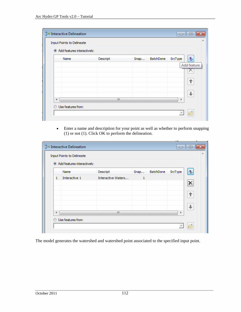
Click Add feature and then click on the map at the location where you want to perform a delineation.
Arc Hydro GP Tools v2.0 – Tutorial
October 2011 112
Enter a name and description for your point as well as whether to perform snapping (1) or not (1). Click OK to perform the delineation.
The model generates the watershed and watershed point associated to the specified input point.
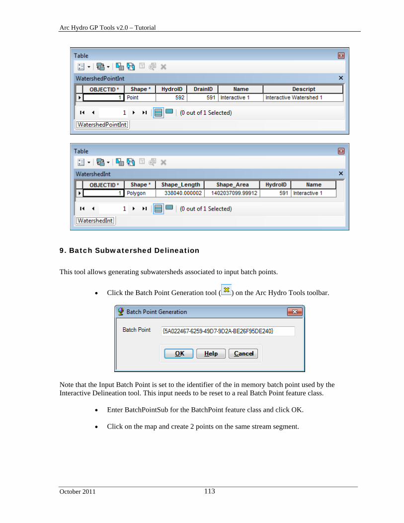
Arc Hydro GP Tools v2.0 – Tutorial
October 2011 113
9. Batch Subwatershed Delineation
This tool allows generating subwatersheds associated to input batch points.
Click the Batch Point Generation tool ( ) on the Arc Hydro Tools toolbar.
Note that the Input Batch Point is set to the identifier of the in memory batch point used by the Interactive Delineation tool. This input needs to be reset to a real Batch Point feature class.
Enter BatchPointSub for the BatchPoint feature class and click OK.
Click on the map and create 2 points on the same stream segment.

Arc Hydro GP Tools v2.0 – Tutorial
October 2011 114
Double-click Watershed Processing > Batch Subwatershed Delineation.
Keep the default for the inputs/outputs and click OK.
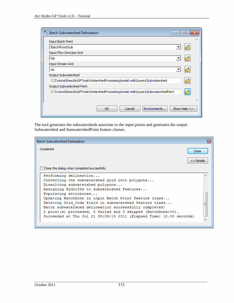
Arc Hydro GP Tools v2.0 – Tutorial
October 2011 115
The tool generates the subwatersheds associate to the input points and generates the output Subwatershed and SunwatershedPoint feature classes.

Arc Hydro GP Tools v2.0 – Tutorial
October 2011 116
10. Batch Watershed Delineation for Polygons
This tool allows generating watersheds draining into polygon features.
Add the NHDWaterbody feature class from the model.mdb geodatabase.
Select the first 2 features in the NHDWaterbody feature class.
Double-click Watershed Processing > Batch Watershed Delineation for Polygons.
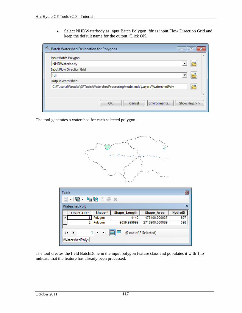
Arc Hydro GP Tools v2.0 – Tutorial
October 2011 117
Select NHDWaterbody as input Batch Polygon, fdr as input Flow Direction Grid and keep the default name for the output. Click OK.
The tool generates a watershed for each selected polygon.
The tool creates the field BatchDone in the input polygon feature class and populates it with 1 to indicate that the feature has already been processed.
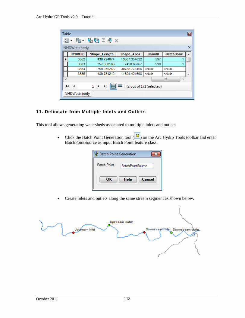
Arc Hydro GP Tools v2.0 – Tutorial
October 2011 118
11. Delineate from Multiple Inlets and Outlets
This tool allows generating watersheds associated to multiple inlets and outlets.
Click the Batch Point Generation tool ( ) on the Arc Hydro Tools toolbar and enter BatchPointSource as input Batch Point feature class.
Create inlets and outlets along the same stream segment as shown below.
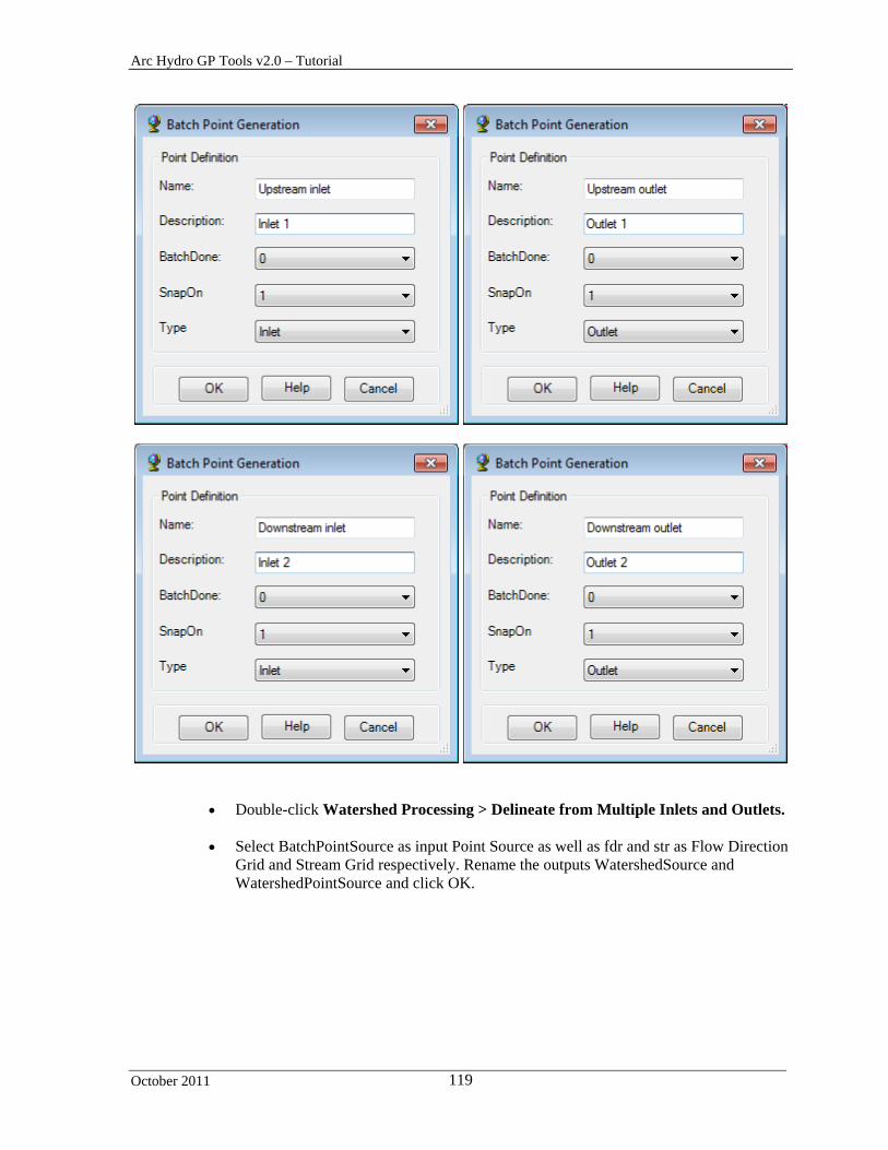
Arc Hydro GP Tools v2.0 – Tutorial
October 2011 119
Double-click Watershed Processing > Delineate from Multiple Inlets and Outlets.
Select BatchPointSource as input Point Source as well as fdr and str as Flow Direction
Grid and Stream Grid respectively. Rename the outputs WatershedSource and WatershedPointSource and click OK.

Arc Hydro GP Tools v2.0 – Tutorial
October 2011 120
The tool generate one watershed for the combined inlets and outlets in the input Point Source feature class.
The tool copies the input points into the WatershedPointSource feature class. The field DrainID stores the HydroID of the associated watershed. The field ONRIVER indicates whether the input point was initially on the stream grid.

Arc Hydro GP Tools v2.0 – Tutorial
October 2011 121
Note The tool does not update the BatchDone field in the input Point Source and does not use this field to find the input points to use for the delineation.
Save and close the map.
12. Batch Global Watershed Delineation
This tool allows generating global watersheds in batch mode. You are going to use the data from \DataGP\GlobalParams to test this tool.
Copy the \DataGP\Global directory under your WatershedProcessing directory.
Open a new map document and save it under the WatershedProcessing directory as WatershedGlobal.mxd.
Browse to the geodatabase Global.mdb and add the hucpoly, streams and
huc_net_junctions feature classes into ArcMap.

Arc Hydro GP Tools v2.0 – Tutorial
October 2011 122
Click the Batch Point Generation tool ( ) on the Arc Hydro Tools toolbar and enter BatchPointGlobal as input Batch Point feature class.
Click on the map and create a few points to delineate in each of the 4 huc polygons.

Arc Hydro GP Tools v2.0 – Tutorial
October 2011 123
Double-click Watershed Processing > Batch Global Watershed Delineation.
Select the inputs as shown below. Browse to the Global directory containing the subfolders for 1111, 2222, etc. Keep the default names for the outputs and click OK.

Arc Hydro GP Tools v2.0 – Tutorial
October 2011 124
The tool delineates a global watershed for each point in the input BatchPointGlobal feature class having BatchDone=0 or Null.
The DrainID field in the GlobalWatershedPoint is the HydroID of the associated GlobalWatershed.
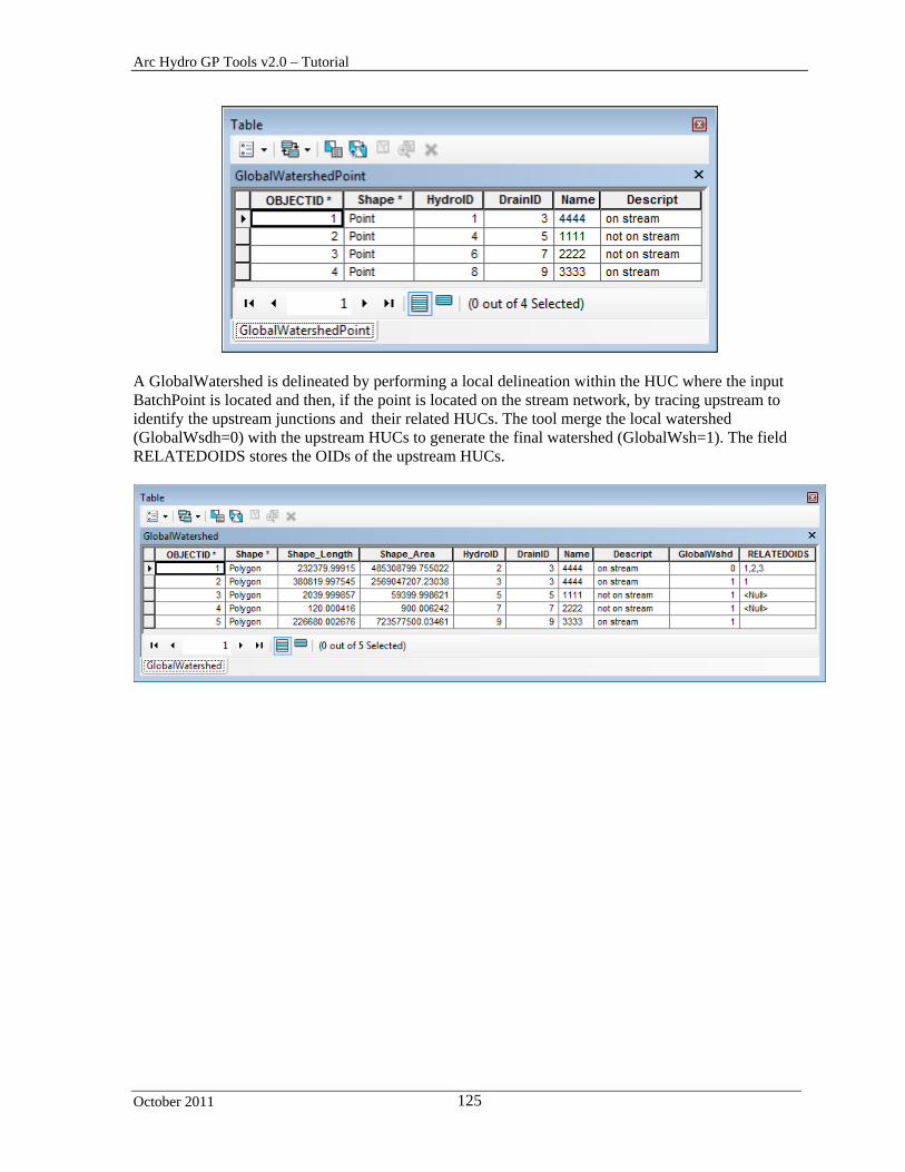
Arc Hydro GP Tools v2.0 – Tutorial
October 2011 125
A GlobalWatershed is delineated by performing a local delineation within the HUC where the input BatchPoint is located and then, if the point is located on the stream network, by tracing upstream to identify the upstream junctions and their related HUCs. The tool merge the local watershed (GlobalWsdh=0) with the upstream HUCs to generate the final watershed (GlobalWsh=1). The field RELATEDOIDS stores the OIDs of the upstream HUCs.

Arc Hydro GP Tools v2.0 – Tutorial
October 2011 126
Utility
There are currently 9 tools in the Utility toolset.
You will use the data from the DataGP\ModelResult folder and from the DataGP\TimeSeries folder to test these tools.
Open a new map document and add the Catchment feature class from the DataGP\ModelResult\Model.mdb geodatabase. Save the map as Utility.mxd in the Utility directory for example.
Reset the vector target location to point to ModelResult\model.mdb using the Arc
Hydro Setup > Set Target Locations tool. The raster location should point to your Utility directory.
In the Arc Hydro Tools toolbox, double-click Watershed Processing > Drainage Area Centroid and create the centroid features associated to the catchments (e.g. Centroid).
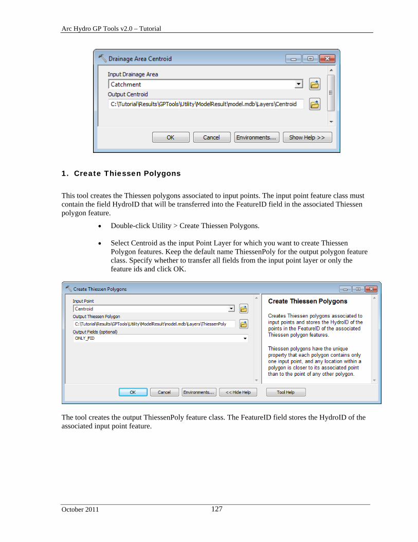
Arc Hydro GP Tools v2.0 – Tutorial
October 2011 127
1. Create Thiessen Polygons
This tool creates the Thiessen polygons associated to input points. The input point feature class must contain the field HydroID that will be transferred into the FeatureID field in the associated Thiessen polygon feature.
Double-click Utility > Create Thiessen Polygons.
Select Centroid as the input Point Layer for which you want to create Thiessen Polygon features. Keep the default name ThiessenPoly for the output polygon feature class. Specify whether to transfer all fields from the input point layer or only the feature ids and click OK.
The tool creates the output ThiessenPoly feature class. The FeatureID field stores the HydroID of the associated input point feature.
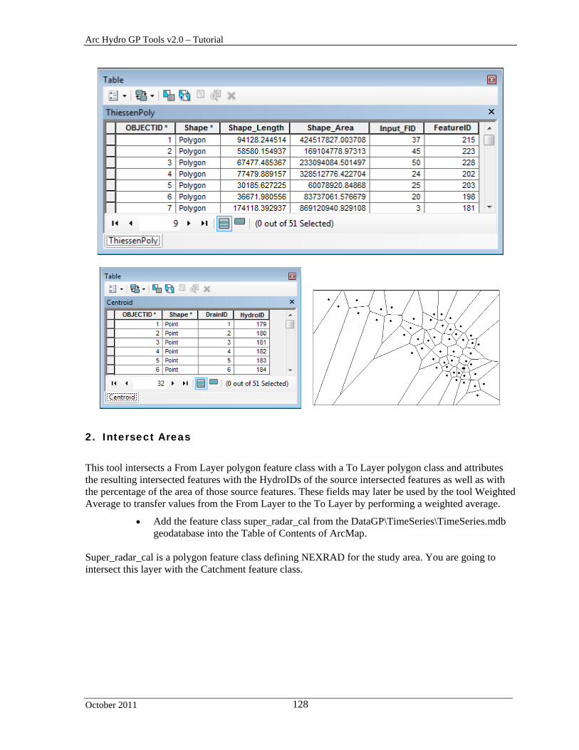
Arc Hydro GP Tools v2.0 – Tutorial
October 2011 128
2. Intersect Areas
This tool intersects a From Layer polygon feature class with a To Layer polygon class and attributes the resulting intersected features with the HydroIDs of the source intersected features as well as with the percentage of the area of those source features. These fields may later be used by the tool Weighted Average to transfer values from the From Layer to the To Layer by performing a weighted average.
Add the feature class super_radar_cal from the DataGP\TimeSeries\TimeSeries.mdb geodatabase into the Table of Contents of ArcMap.
Super_radar_cal is a polygon feature class defining NEXRAD for the study area. You are going to intersect this layer with the Catchment feature class.

Arc Hydro GP Tools v2.0 – Tutorial
October 2011 129
Double-click Utility > Intersect Areas.
Select super_radar_cal as From Layer and Catchment as To Layer. Rename the output Intersect Polygon radarcat.
Specify the attributes from the source layers that should be in the resulting layer.
Defaults to ONLY_FID. Note that if you select ALL, the HydroID fields of the source layers will not be exported into HydroID and HydroID_1 fields in the new layer. The HydroID field in the resulting layer will contain new values uniquely identifying each resulting feature in the geodatabase. Click OK.
The tool intersects the 2 source polygon feature classes and for each feature in the resulting intersected feature class, it stores the HydroID of the source features in the KeyFrom and KeyTo fields and the percentage of the areas in the PctFrom and PctTo fields. The HydroID field uniquely identifies the resulting features in the target geodatabase.

Arc Hydro GP Tools v2.0 – Tutorial
October 2011 130
3. Weighted Averages
This tool transfers values from a From Layer feature class to a To Layer feature class by computing area weighted average using the intersect layer created by the tool Intersect Areas.
You are going to use this tool to generate the values of precipitation over each catchment based on the values of precipitation associated to the NEXRAD cells.
Double-click Utility > Weighted Averages.
Select super_rad_cal as input From Layer for Intersect polygon feature class and SUM_ as Transfer Value Field.
Select Catchment as input To Layer and radarcat as Input Intersect Polygon. Click
OK.
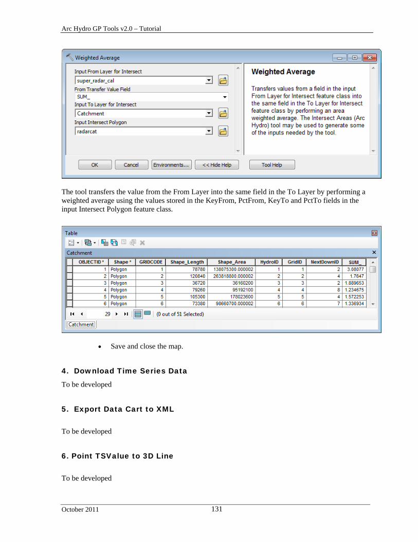
Arc Hydro GP Tools v2.0 – Tutorial
October 2011 131
The tool transfers the value from the From Layer into the same field in the To Layer by performing a weighted average using the values stored in the KeyFrom, PctFrom, KeyTo and PctTo fields in the input Intersect Polygon feature class.
Save and close the map.
4. Download Time Series Data
To be developed
5. Export Data Cart to XML
To be developed
6. Point TSValue to 3D Line
To be developed

Arc Hydro GP Tools v2.0 – Tutorial
October 2011 132
7. Update TSValue on Points
To be developed
8. Convert 3D Line to Raster
To be developed
9. Spatial Reference from Raster
To be developed

Arc Hydro GP Tools v2.0 – Tutorial
October 2011 133
Terrain Morphology The Terrain Morphology toolset contains 3 subtoolsets that are used to process deranged terrains.
The Drainage Boundary Processing toolset allows generating and characterizing 3D drainage boundaries. You are going to use the data from DataGP\Morphology to test these tools.
Copy the DataGP\Morphology directory (e.g. Results\GPTools\Morphology).
Open a new map. Add the Catchment and the DrainagePoint feature classes from the newly copied Morphology.gdb geodatabase, the elevation grid elev_cm, the filled DEM Fil and the flow direction grid fdr. Save the map as Morphology.mxd.
The default target locations points to the Morphology directory and to the existing geodatabase Morphology.gdb in that directory. You can use ApUtilities > Set Target Locations for the HydroConfig node to view the locations.
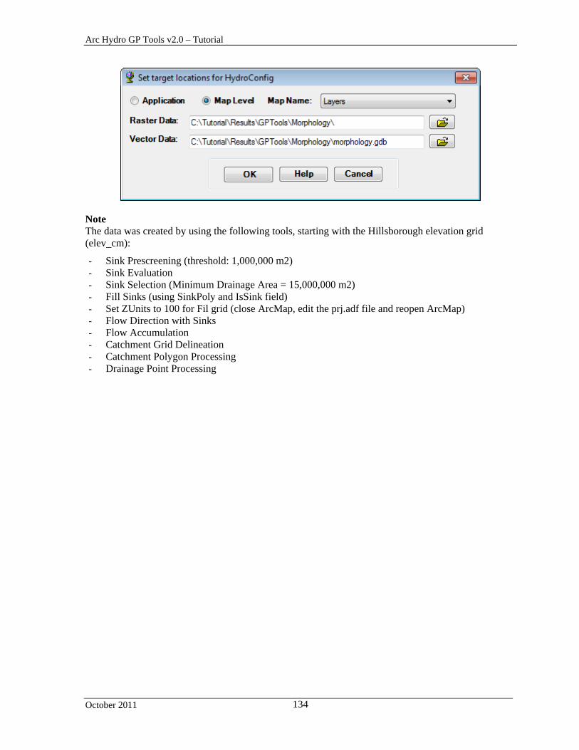
Arc Hydro GP Tools v2.0 – Tutorial
October 2011 134
Note The data was created by using the following tools, starting with the Hillsborough elevation grid (elev_cm):
- Sink Prescreening (threshold: 1,000,000 m2) - Sink Evaluation - Sink Selection (Minimum Drainage Area = 15,000,000 m2) - Fill Sinks (using SinkPoly and IsSink field) - Set ZUnits to 100 for Fil grid (close ArcMap, edit the prj.adf file and reopen ArcMap) - Flow Direction with Sinks - Flow Accumulation - Catchment Grid Delineation - Catchment Polygon Processing - Drainage Point Processing

Arc Hydro GP Tools v 2.0 – Tutorial
October 2011 135
Drainage Boundary Processing Toolset
1. Drainage Area Characterization
This tool allows characterizing Drainage Areas.
Double-click Terrain Morphology > Drainage Area Characterization. Select Catchment as input Drainage Area and the filled DEM Fil as input DEM. Set the Exclusion Area to blank. Set the Extrusion Value to 10 and the Slice Count to 3.Keep the defaults for the output and click OK.
The tool generates the output DrainEAV table that characterizes slices of each input Drainage Area feature. One record is created for each slice (3), one additional record characterizes the bottom of the area and another the extruded slice (if an extrusion value is specified).
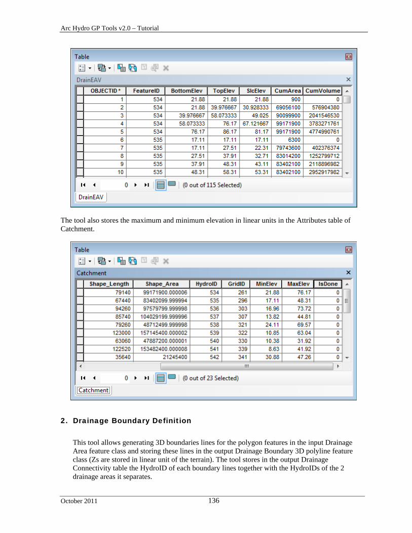
Arc Hydro GP Tools v2.0 – Tutorial
October 2011 136
The tool also stores the maximum and minimum elevation in linear units in the Attributes table of Catchment.
2. Drainage Boundary Definition
This tool allows generating 3D boundaries lines for the polygon features in the input Drainage Area feature class and storing these lines in the output Drainage Boundary 3D polyline feature class (Zs are stored in linear unit of the terrain). The tool stores in the output Drainage Connectivity table the HydroID of each boundary lines together with the HydroIDs of the 2 drainage areas it separates.

Arc Hydro GP Tools v2.0 – Tutorial
October 2011 137
The tool works on all features in the input Drainage Areas feature class. Drainage areas with internal pits need to be characterized as such before running this function by setting the attribute “IsPitted” to 1 in the input Drainage Area feature class. This is required because only the boundary lines associated to pitted drainage areas will be processed by the function “Drainage Connectivity Characterization”. By default, if the field IsPitted (short integer) does not exist or does not contain any 0 or 1, the tool will assume that all area features are pitted. The tool will create the field IsPitted and populates it with 1.
Double-click Terrain Morphology > Drainage Boundary Processing > Drainage Boundary Definition. Select Catchment as input Drainage Area and the filled DEM Fil as input DEM. Keep the defaults for the output and click OK.
The tool generates the output 3D Drainage Boundary feature class. The field IsIncluded is set to 1 if at least one of the areas separated by the boundary line has the field IsSink set to 1. The field IsDone is populated with 0.
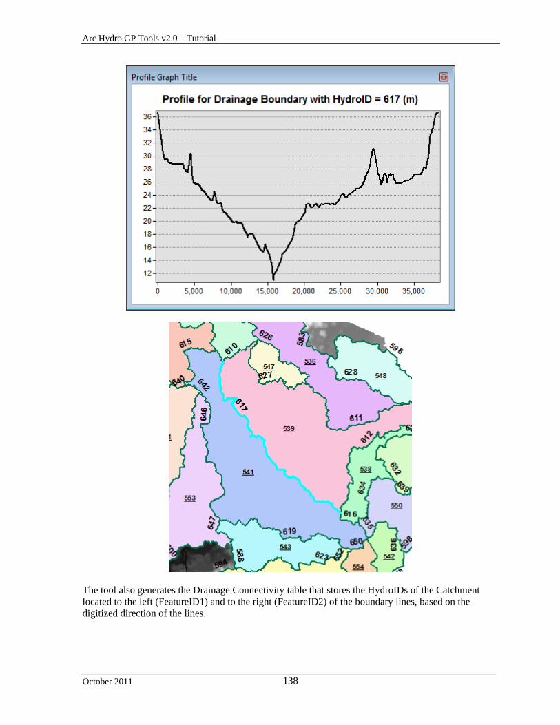
Arc Hydro GP Tools v2.0 – Tutorial
October 2011 138
The tool also generates the Drainage Connectivity table that stores the HydroIDs of the Catchment located to the left (FeatureID1) and to the right (FeatureID2) of the boundary lines, based on the digitized direction of the lines.

Arc Hydro GP Tools v2.0 – Tutorial
October 2011 139
The tool creates the field IsPitted that did not exist and populates it with 1.
3. Drainage Boundary Direction
This tool allows setting the digitized direction of the selected Drainage Boundary lines based on user-provided Preferential Link line features. A Preferential Link is a line feature that connects 2 Drainage Area features and its direction defines the preferred flowpath between the 2 Drainage Area features. The digitized direction of a Drainage Boundary line is set from left to right when looking in the digitized direction of the intersecting Preferential Link feature.
Add the PrefLink feature class into the Table of Contents of ArcMap and modify the symbology of PrefLink and DrainageBoundary so that you can see the digitized directions of the lines.
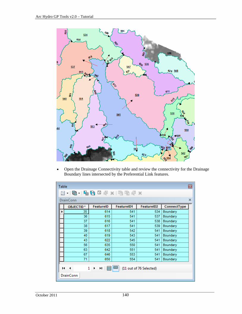
Arc Hydro GP Tools v2.0 – Tutorial
October 2011 140
Open the Drainage Connectivity table and review the connectivity for the Drainage Boundary lines intersected by the Preferential Link features.

Arc Hydro GP Tools v2.0 – Tutorial
October 2011 141
Double-click Terrain Morphology > Drainage Boundary Processing > Drainage
Boundary Direction. Select the inputs as shown below and click OK.
Refresh the map and review the direction of the Drainage Boundary lines as well as the Drainage Connectivity table.

Arc Hydro GP Tools v2.0 – Tutorial
October 2011 142
The directions of the lines have been modified using the digitized direction of the intersecting PrefLink features. The fields FeatureID1 and FeatureID2 in the Drainage Connectivity table have been updated to match the new directions.
4. Cross Section Direction
This tool allows setting the orientation of a cross section from left to right when looking in the digitized direction of the intersecting input Line feature. If there is no intersecting Line feature, the direction of the cross section will not be modified. The tool works on a selected set of cross section features. The tool will process all the cross section features if there is no selected set.
Add the CrossSection feature class into the Table of Contents of ArcMap. Review the directions of the Cross Section features.
Double-click Terrain Morphology > Drainage Boundary Processing > Cross
Section Direction. Select CrossSection as Input Cross Section and DrainageBoundary as Input Line and click OK.

Arc Hydro GP Tools v2.0 – Tutorial
October 2011 143
Review the directions of the Cross Section features. Directions have been modified to match the direction of the intersecting Drainage Boundary features.
5. Elevation-Width-Area Characterization
This tool allows computing the width, perimeter and cross-section area associated with slices of 3D lines and stores these characteristics in the output “Boundary EWA” table.
Double-click Terrain Morphology > Drainage Boundary Processing > Elevation-Width-Area Characterization.
Select DrainageBoundary as Input Line 3D and Slice Count to 3. Keep the defaults for
the other inputs/outputs. Leave Z Factor to 1 as the elevations in the 3D lines already take into account the Z Factor of the elevation DEM elev_cm. Click OK.
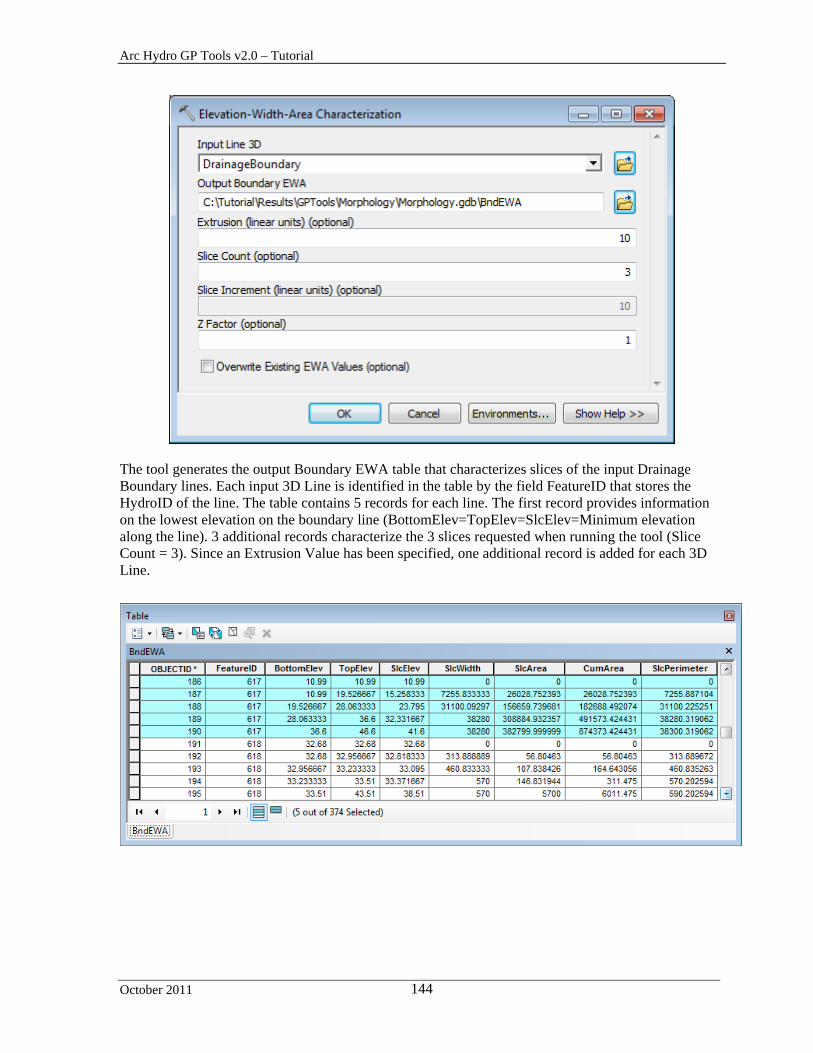
Arc Hydro GP Tools v2.0 – Tutorial
October 2011 144
The tool generates the output Boundary EWA table that characterizes slices of the input Drainage Boundary lines. Each input 3D Line is identified in the table by the field FeatureID that stores the HydroID of the line. The table contains 5 records for each line. The first record provides information on the lowest elevation on the boundary line (BottomElev=TopElev=SlcElev=Minimum elevation along the line). 3 additional records characterize the 3 slices requested when running the tool (Slice Count = 3). Since an Extrusion Value has been specified, one additional record is added for each 3D Line.

Arc Hydro GP Tools v2.0 – Tutorial
October 2011 145
6. Station-Elevation Characterization
This tool allows computing Station (Measure)-Elevation for each vertex in the input 3D line. The tool works on a selected set of 3D lines and will process all the lines if there is no selected set.
Double-click Terrain Morphology > Drainage Boundary Processing > Station-Elevation Characterization. Select DrainageBoundary as input Line 3D and click Select All to select all measure formats. Do not check “Use M Value from Line” as the measures are not populated in the Drainage Boundary feature class. Click OK.

Arc Hydro GP Tools v2.0 – Tutorial
October 2011 146
The tool generates the output Station Elevation table that stores the measure and elevation for each vertex in the input Line 3D feature class.

Arc Hydro GP Tools v2.0 – Tutorial
October 2011 147
7. Drainage Boundary Smoothing
This tool allows creating new Smooth Drainage Boundary features with jaggy removed by applying out-of-the-box smoothing algorithms (PEAK) to the input Drainage Boundary feature class. The intent is to generate a line that will closely represent the true length of the Drainage Boundary feature.
Double-click Terrain Morphology > Drainage Boundary Processing > Drainage Boundary Smoothing. Select DrainageBoundary as input Drainage Boundary. The Smoothing Tolerance has to be greater than 0. Set it to 10 meters for example and click OK.
The tool generates the smoothed 3D Drainage Boundary feature class. The FeatureID field in that feature class stores the HydroID of the associated input Drainage Boundary feature.

Arc Hydro GP Tools v2.0 – Tutorial
October 2011 148
8. Drainage Connectivity Characterization
This tool allows creating the network connectivity between areas involving at least one deranged area. The tool does not create the geometric network since it may already have been created by the dendritic processing.
Double-click Terrain Morphology > Drainage Boundary Processing > Drainage
Connectivity Characterization. Select DrainageBoundary as input Drainage Boundary. The Smoothing Tolerance has to be greater than 0. Set it to 10 meters for example and click OK.

Arc Hydro GP Tools v2.0 – Tutorial
October 2011 149
The tool generates HydroEdge and HydroJunction feature classes if they do not already exist but it does not generate the geometric network.
The tool populates the DrainID field with the HydroID of the drainage area (catchment) associate to the HydroEdge. The HydroEdge features of type Boundary Link connects boundary nodes to sink nodes.
The BoundaryDrainageLine features also connect boundary nodes to sink nodes. The field LinkID stores the HydroID of the associated Drainage Boundary feature.

Arc Hydro GP Tools v2.0 – Tutorial
October 2011 150
The tool also updates the field IsDone with 1 in the Attributes table of the Drainage Boundary feature class to indicate that the drainage boundary feature has been processed.

Arc Hydro GP Tools v2.0 – Tutorial
October 2011 151
AH Connectivity Refinement Toolset The Arc Hydro Connectivity Refinement Toolset contains a set of tools that allow adding the impact of existing structures to the connectivity established based on the terrain. It builds on the existing network generated using the Drainage Connectivity Characterization tool available in the Terrain Morphology > Drainage Boundary Toolset.
1. Sink Identification by HEP
This tool allows settings the field IsSink to 1 in the input Sink Polygon features containing Hydraulic Element Point features. The field IsSink will be created if it does not already exist.
The tool works on a selected set of Sink Polygon features. It will process all features if there is no selected set.
Add the SinkPoly and SinkPoint feature classes into the Table of Contents of ArcMap. Open the attributes table of SinkPoly and use the Field Calculator to set the field IsSink to 0 for all records.
Double-click Terrain Morphology > AH Connectivity Refinement Tools > Sink
Identification by HEP. Specify SinkPoly and SinkPoint as inputs and click OK.
The tool populates the field IsSink with 1 for all the SinkPoly features containing a SinkPoint feature.

Arc Hydro GP Tools v2.0 – Tutorial
October 2011 152
2. Connect HydroJunctions
This tool allows connecting structures HydroJunctions located on the Drainage Boundaries. You need to create the geometric network based on the HydroJunction and HydroEdge feature classes.
Open the Catalog window in ArcMap and browse to the target dataset. Right click the feature dataset (e.g. Layers in Morphology.gdb) and select New > Geometric Network.
Rename the network ArcHydro and choose to snap using the default tolerance
provided. Click Next.
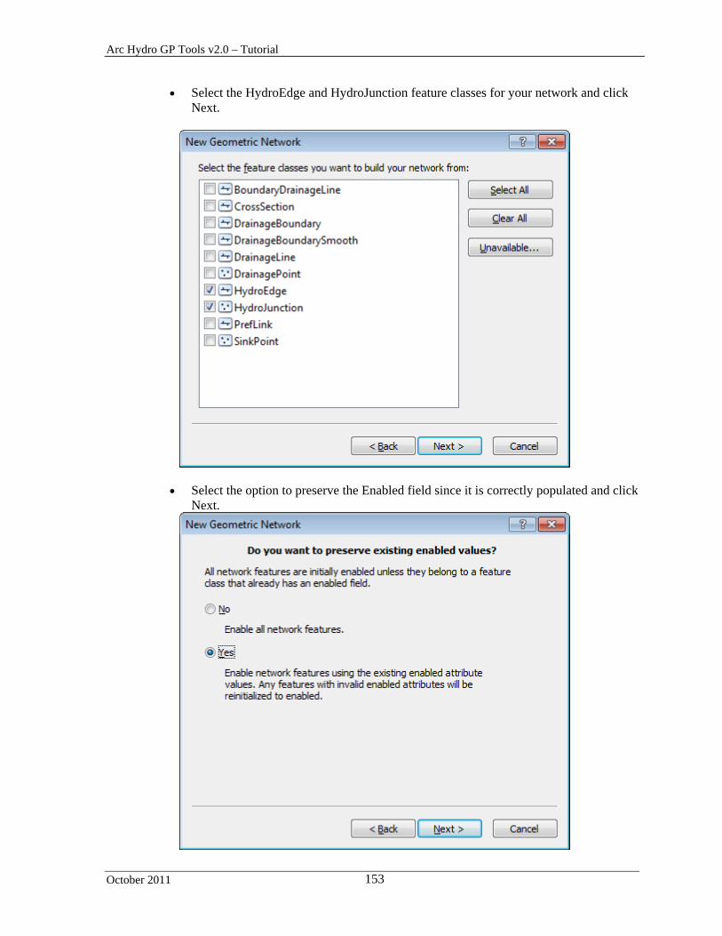
Arc Hydro GP Tools v2.0 – Tutorial
October 2011 153
Select the HydroEdge and HydroJunction feature classes for your network and click Next.
Select the option to preserve the Enabled field since it is correctly populated and click Next.

Arc Hydro GP Tools v2.0 – Tutorial
October 2011 154
Select Simple Edge and Simple Junction for the Role and do not set any source or sink. Click Next and keep the default in the remaining windows and create the network.
The network you just created has uninitialized flow directions. You need to set the flow direction in .g. in the digitized direction before using the tools.
Click Network Tools > Set Flow Direction. Select HydroEdge and With Digitized Direction and click OK to set the flow direction in the network.
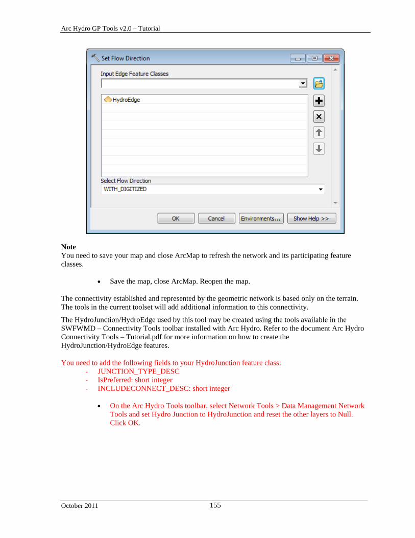
Arc Hydro GP Tools v2.0 – Tutorial
October 2011 155
Note You need to save your map and close ArcMap to refresh the network and its participating feature classes.
Save the map, close ArcMap. Reopen the map. The connectivity established and represented by the geometric network is based only on the terrain. The tools in the current toolset will add additional information to this connectivity.
The HydroJunction/HydroEdge used by this tool may be created using the tools available in the SWFWMD – Connectivity Tools toolbar installed with Arc Hydro. Refer to the document Arc Hydro Connectivity Tools – Tutorial.pdf for more information on how to create the HydroJunction/HydroEdge features. You need to add the following fields to your HydroJunction feature class:
- JUNCTION_TYPE_DESC - IsPreferred: short integer - INCLUDECONNECT_DESC: short integer
On the Arc Hydro Tools toolbar, select Network Tools > Data Management Network
Tools and set Hydro Junction to HydroJunction and reset the other layers to Null. Click OK.

Arc Hydro GP Tools v2.0 – Tutorial
October 2011 156
The fields defined in the XML configuration for HydroJunction and missing in the feature class are appended, including the 3 missing fields: IsPreferred, INCLUDECONNECT_DESC and JUNCTION_TYPE_DESC..
You are going to create a new HydroJunction representing a Culvert point structure on the boundary line between catchments 547 and 539.
Start editing and add a new Hydro Junction feature on the Drainage Boundary feature between Catchment 547 and 539. Set the fields as follows: JUNCTION_PLACEMENT_DESC: ‘MANUAL’ HYDRAULIC_TYPE_DESC: ‘CULVERT’ JUNCTION_TYPE_DESC: ‘HYDRAULIC ELEMENT’ IsPreferred: ‘1’ INCLUDECONNECT_DESC to ‘1’
Save your edits and stop editing.

Arc Hydro GP Tools v2.0 – Tutorial
October 2011 157
Zoom in to the HydroJunction you just created. Since you did not set the snapping environment, the HydroJunction may not be exactly on top of the DrainageBoundary feature. You are going to snap the HydroJunction onto the boundary.
Add the SWFWMD – Connectivity Tools toolbar.
Select the HydroJunction you just created and select Connectivity > Snap HydroJunctions. Specify the input DrainageBoundary and Hydro Junction feature classes and click OK.
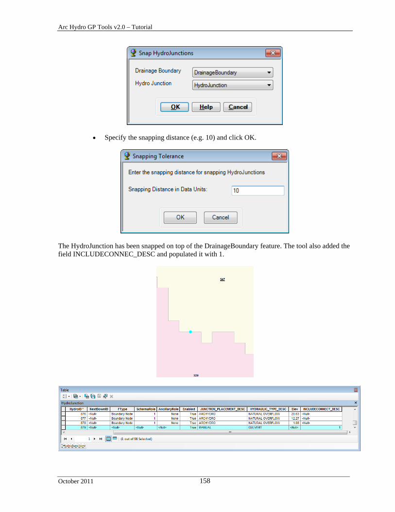
Arc Hydro GP Tools v2.0 – Tutorial
October 2011 158
Specify the snapping distance (e.g. 10) and click OK.
The HydroJunction has been snapped on top of the DrainageBoundary feature. The tool also added the field INCLUDECONNEC_DESC and populated it with 1.

Arc Hydro GP Tools v2.0 – Tutorial
October 2011 159
You now need to create the HydroEdges associated to this new HydroJunction – they will link the HydroJunction to the Sink Node HydroJunction in each catchment.
Double-click Terrain Morphology > AH Connectivity Refinement Tools > Connect HydroJunctions. Specify the inputs as shown below and click OK.
The tool creates 2 new HydroEdge features of type Structure Link with their attribute IsPreferred set to 1.

Arc Hydro GP Tools v2.0 – Tutorial
October 2011 160
3. Connect Control Structure Junctions
This tool allows connecting HydroJunctions of Hydraulic Type Inlet/Outlet and Control Structure associated to a Control Structure Sequence to the spider web geometric network. A Control Structure Sequence is defined as one or many linear structures and point structures connected together through HydroJunctions and HydroEdges to move water between Catchments. You are going to create a few inlets and connected structure. Only the HydroJunctions having HYDRAULIC_TYPE_DESC=’INLET’ or ‘CONTROL STRUCTURE (‘CS’) and INCLUDECONNECT_DESC = 1or Null will be processed by the function.
Select Start Editing and create the following template for HydroJunction by setting the fields Enabled to True, JUNCTION_PLACEMENT_DESC to MANUAL, HYDRAULIC_TYPE_DESC to INLET and INCLUDECONNECT_DESC to 1.
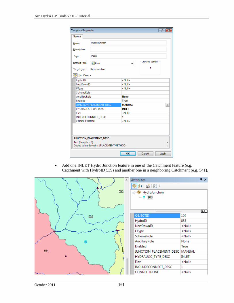
Arc Hydro GP Tools v2.0 – Tutorial
October 2011 161
Add one INLET Hydro Junction feature in one of the Catchment feature (e.g. Catchment with HydroID 539) and another one in a neighboring Catchment (e.g. 541).
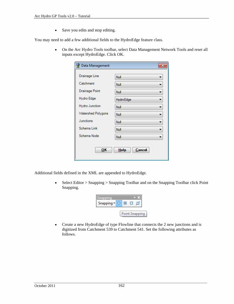
Arc Hydro GP Tools v2.0 – Tutorial
October 2011 162
Save you edits and stop editing. You may need to add a few additional fields to the HydroEdge feature class.
On the Arc Hydro Tools toolbar, select Data Management Network Tools and reset all inputs except HydroEdge. Click OK.
Additional fields defined in the XML are appended to HydroEdge.
Select Editor > Snapping > Snapping Toolbar and on the Snapping Toolbar click Point Snapping.
Create a new HydroEdge of type Flowline that connects the 2 new junctions and is digitized from Catchment 539 to Catchment 541. Set the following attributes as follows.

Arc Hydro GP Tools v2.0 – Tutorial
October 2011 163
Set the Flow Direction in the digitized direction using Network Tools > Set Flow Direction.
Double-click Terrain Morphology > AH Connectivity Refinement Tools > Connect
Control Structure Junctions. Specify the inputs as shown below and click OK.

Arc Hydro GP Tools v2.0 – Tutorial
October 2011 164
The tool traces from the HydroJunctions (inlet/control structures) using the geometric network and the flow direction grid and connects the HydroJunctions to the closest Drainage Line or Sink. The tool sets the flow direction in the digitized direction for the new Hydro Edge features.
The field HYDROEDGE_HYDRAULIC_TYPE_DESC is populated with SC (SHALLOW CONCENTRATED) for the newly created HydroEdge features.
Note CHAN (CHANNEL) is reserved for Hydro Edge features that are manually digitized (like Conduit) but are channels.
The field IsPreferred is populated with 1 to indicate a preferred path. If new HydroJunctions are created (when there are no existing junctions at the ends of the new HydroEdges, which is not the case in this example), the field IsPreferred is also populated with 1 for the new HydroJunctions.
4. Define Overland Preferential Node Link Schema
Note Before using this tool, make sure the geoprocessing setting is set to allow you to overwrite the results of the geoprocessing operations. This setting is required to allow you to update and append/replace records in the output Preferential Node and Link feature classes. If you do not allow overwriting, two new Preferential Link/Node feature classes will be generated each time you run the tool.

Arc Hydro GP Tools v2.0 – Tutorial
October 2011 165
This tool allows creating a Preferential Node/Link schema that defines the “main” overland flow paths of type Boundary Link between Catchment features. The input HydroEdge, HydroJunction and DrainageBoundary feature classes used by the tool are the ones created with the Terrain Morphology Drainage Connectivity Characterization function, and NOT the ones created manually and/or during the creation of HEPs (Structure Link) that will be handled by the tools Add Point Structure HydroEdges to Preferential Path and Add Linear HydroEdges to Preferential Path.
Double-click Terrain Morphology > AH Connectivity Refinement Tools > Define
Overland Preferential Node Link Schema.
Specify the inputs as shown and rename the output PreferentialLink “PreferentialLink”. Click OK.
The tool generates the PreferentialLink and PreferentialNode feature classes that identify the preferred path from one catchment SinkPoint into the next catchment using Boundary Link HydroEdges.

Arc Hydro GP Tools v2.0 – Tutorial
October 2011 166
For each Catchment feature being processed, the tool finds the sink point feature within the catchment and copies this point into the output “Preferential Node” feature class. It populates the HydroID field with a new unique identifier and the field SinkID with the HydroID of the source Sink Point. The DrainID field is populated with the HydroID of the Catchment feature.
The tool identifies the connected catchment by looking for the HydroJunction features located on the Catchment’s associated Drainage Boundary features and identifying the HydroJunction that has the lowest elevation. The elevations are retrieved from the input Drainage Boundary feature class.
The tool looks for connected HydroEdges of type ‘Boundary Link’ at that location that belong to an adjacent catchment:

Arc Hydro GP Tools v2.0 – Tutorial
October 2011 167
- If the tool cannot find an adjacent HydroEdge/Catchment, it creates a Preferential Path that starts at the sink and ends at the lowest HydroJunction on the boundary. The tool creates a Preferential Node at the location of the lowest HydroJunction and populates its SinkID and DrainID with -1.
- If the tool finds one or many connected HydroEdges, for each connected feature it merges the
geometries of the Hydro Edges connecting at that lowest Hydro Junction that link the sink points of these 2 catchments. It stores the resulting line in the output “Preferential Link” feature class and populates its HydroID. The tool sets the field IsPreferred to 1 in the HydroEdge features merged to create the Preferential Link.
The tool identifies the lowest HydroJunction features located along all Drainage Boundary features of the identified adjacent catchment at the exclusion of the Drainage Boundary features associated to the first catchment. If its elevation is lower than the elevation of the HydroJunction previously identified, the first catchment is flowing into the second catchment 2. The tool sets the digitized direction of the Preferential Link from the first to the second catchment 2 and populates the fields in the attributes table of Preferential Link as follows:
- FlowDir: “WithDigitized” - FNID: HydroID of the Preferential Node in Catchment 1 - TNID: HydroID of the Preferential Node in Catchment 2 - FeatureID1: HydroID of Catchment 1 - FeatureID2: HydroID of Catchment 2
If the elevation of the second HydroJunction is higher, the second catchment is flowing into the first catchment. The tool sets the digitized direction of the Preferential Link from Catchment 2 to Catchment 1 and populates the fields in the attributes table of Preferential Link as follows:
- FlowDir: “WithDigitized” - FNID: HydroID of the Preferential Node in Catchment 2 - TNID: HydroID of the Preferential Node in Catchment 1 - FeatureID1: HydroID of Catchment 2 - FeatureID2: HydroID of Catchment 1
If both elevations are the same, the tool sets the digitized direction of the Preferential Link from the smaller catchment to the larger catchment. The tool populates the field FlowDir with “WithDigitized”. The tool sets the processing flag to both Catchments to Done to skip processing Catchment 2 in the subsequent loop. It populates the following fields in the attributes table of Preferential Link as follows:
- FlowDir: “WithDigitized” - FNID: HydroID of the Preferential Node in smaller Catchment - TNID: HydroID of the Preferential Node in larger Catchment - FeatureID1: HydroID of smaller Catchment - FeatureID2: HydroID of larger Catchment
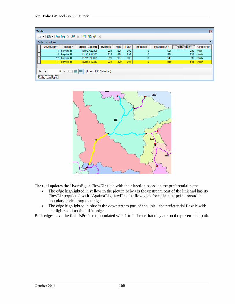
Arc Hydro GP Tools v2.0 – Tutorial
October 2011 168
The tool updates the HydroEge’s FlowDir field with the direction based on the preferential path:
The edge highlighted in yellow in the picture below is the upstream part of the link and has its FlowDir populated with “AgainstDigitized” as the flow goes from the sink point toward the boundary node along that edge.
The edge highlighted in blue is the downstream part of the link – the preferential flow is with the digitized direction of its edge.
Both edges have the field IsPreferred populated with 1 to indicate that they are on the preferential path.

Arc Hydro GP Tools v2.0 – Tutorial
October 2011 169
The edges that do not belong to the preferential path have IsPreferred set to Null or 0 and FlowDir set Uninitialized.
Note You can use the FlowDir field to set the flow direction in the geometric network using the preferential flow path.
5. Flip Preferential Path
This tool allows flipping the geometries of preferential path features as well as the directional attributes in Preferential Path attributes table and the FlowDir field in the associated HydroEdge features. The tool works on a selected set of preferential links.

Arc Hydro GP Tools v2.0 – Tutorial
October 2011 170
For example, you are going to flip the path so that Catchment 556 flows into Catchment 555 instead of the opposite.
Select the preferential paths linking the 2 Catchments and review their attributes.
The attributes shows that the preferential path goes from 555 to 556 and ends on the boundary of 556 (FeatureID2 = -1) and that the path is the original path generated by the tool and has not been flipped (IsFlipped = 0).
Select the underlying HydroEdge features using select by Location as shown below.
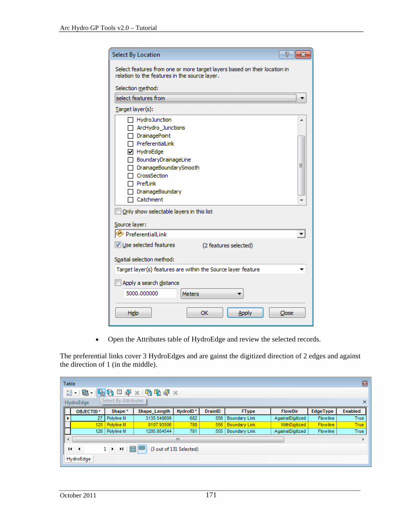
Arc Hydro GP Tools v2.0 – Tutorial
October 2011 171
Open the Attributes table of HydroEdge and review the selected records. The preferential links cover 3 HydroEdges and are gainst the digitized direction of 2 edges and against the direction of 1 (in the middle).

Arc Hydro GP Tools v2.0 – Tutorial
October 2011 172
Make sure the links are selected and click Flip Preferential Path. Select Preferential Link and HydroEdge as inputs and click OK.
The digitized direction of the links has been flipped and the values in FeatureID1 and FeatureID2 have been switched. The field IsFlipped is now populated with 1.
Reselect the underlying edges.

Arc Hydro GP Tools v2.0 – Tutorial
October 2011 173
The attribute FlowDir has been switched from WitHDigitized to AgainstDigitized and vice versa to indicate that the direction of the preferential links has changed compare to the digitized direction of the Hydro Edge features.
6. Add Point Structure HydroEdges to Preferential Link
Note Before using this tool, make sure the geoprocessing setting is set to allow you to overwrite the results of the geoprocessing operations. This setting is required to allow you to update and append/replace records in the output Preferential Node and Link feature classes. If you do not allow overwriting, two new Preferential Link/Node feature classes will be generated each time you run the tool. This tool allows generating Preferential Links and Nodes associated to HydroJunctions of hydraulic type Culvert (‘CULV’), Control Structure (‘CS’) or Bridge (‘BRID’). The tool works on a selected set of ‘HydroJunction’ features. If nothing is selected, all features will be processed. The tool will not overwrite any existing links or nodes.
The tool loops through all selected HydroJunctions and processes only the HydroJunction features that have the following attributes:
IsPreferred=1 HYDRAULIC_TYPE_DESC in (‘CULV’, ‘BRID’, ‘CS’)
and are connected to at least one HydroEdge having IsPreferred=1.
Note Although the tool processes all features when there is no selection, it is better to work on selected features as this is a GIS intensive function and quality control at each step is essential.
Select the HydroJunction feature of type Culvert you just created and set its field
IsPreferred to 1. Double-click Terrain Morphology > AH Connectivity Refinement Tools > Add Point Structure HydroEdges to Preferential Link.
Select the input Hydro Junction, Hydro Edge, Sink Point, and Catchment feature
classes. Specify the Preferential Link and Preferential Node you just created as output so that the tool updates these existing feature classes. Set the optional Hydraulic Element Point feature class to blank.
The tool will display a yellow warning sign indicating that the feature classes will be overwritten. In reality, the tool will append new records in these feature classes and not overwrite the existing Preferential Link and Node features.
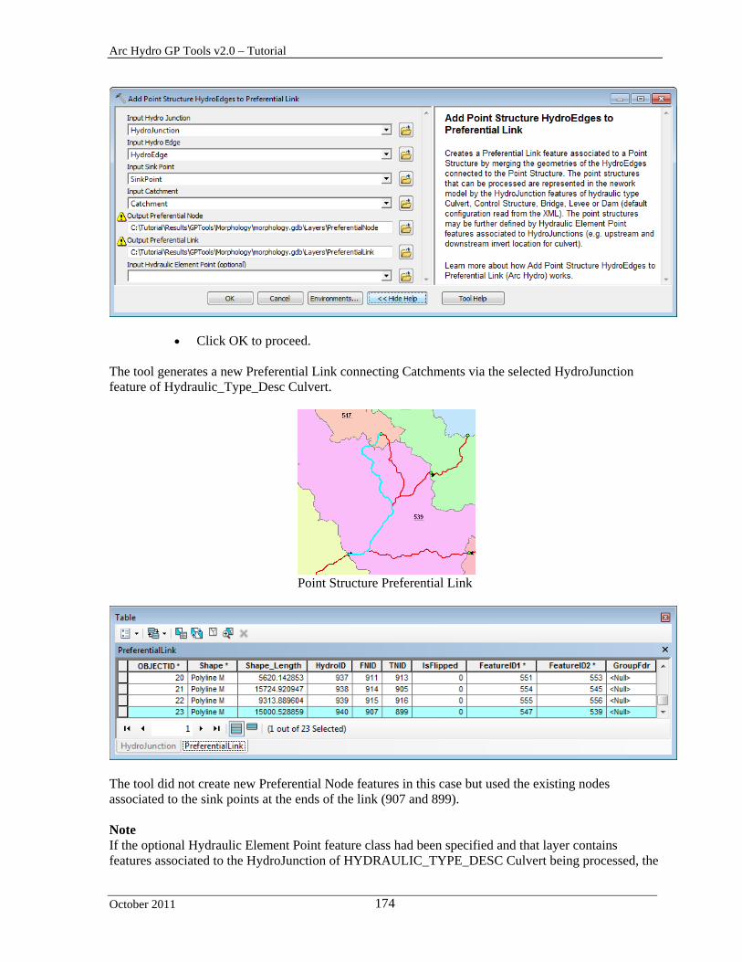
Arc Hydro GP Tools v2.0 – Tutorial
October 2011 174
Click OK to proceed. The tool generates a new Preferential Link connecting Catchments via the selected HydroJunction feature of Hydraulic_Type_Desc Culvert.
Point Structure Preferential Link
The tool did not create new Preferential Node features in this case but used the existing nodes associated to the sink points at the ends of the link (907 and 899). Note If the optional Hydraulic Element Point feature class had been specified and that layer contains features associated to the HydroJunction of HYDRAULIC_TYPE_DESC Culvert being processed, the

Arc Hydro GP Tools v2.0 – Tutorial
October 2011 175
direction of the preferential link will be set using the direction set by the elements instead of using the lowest elevation on the boundary of the catchments.
7. Update Preferential Node Link Schema
Note Before using this tool, make sure the geoprocessing setting is set to allow you to overwrite the results of the geoprocessing operations. This setting is required to allow you to update and append/replace records in the output Preferential Node and Link feature classes. If you do not allow overwriting, two new Preferential Link/Node feature classes will be generated each time you run the tool. This tool allows generating the Preferential Node and Link feature classes by using the HydroEdge features of FType Boundary Link or Structure Link having the field IsPreferred set to 1. This tool may be used after editing the field IsPreferred in the HydroEdge features of type Boundary Link or Structure Link to modify the desired Preferential Paths.
For example, you are now going to modify the preferential path so that Catchment 544 is not terminal but flows into Catchment 555.
Set the field IsPreferred to 1 for the 2 HydroEdges connecting 544 and 555.
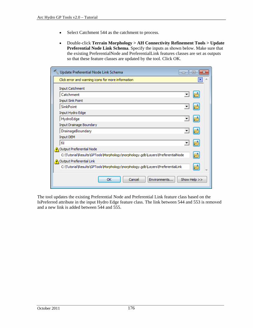
Arc Hydro GP Tools v2.0 – Tutorial
October 2011 176
Select Catchment 544 as the catchment to process.
Double-click Terrain Morphology > AH Connectivity Refinement Tools > Update Preferential Node Link Schema. Specify the inputs as shown below. Make sure that the existing PreferentialNode and PreferentialLink features classes are set as outputs so that these feature classes are updated by the tool. Click OK.
The tool updates the existing Preferential Node and Preferential Link feature class based on the IsPreferred attribute in the input Hydro Edge feature class. The link between 544 and 553 is removed and a new link is added between 544 and 555.

Arc Hydro GP Tools v2.0 – Tutorial
October 2011 177
Note The Update tool maintains the flipped path between Catchments 553 and 556. You are now going to reset these links to their original direction.
Select the link between 555 and 556 and the link from the boundary of 556 to its preferential node and click Flip Preferential Path.
The paths are reset in their original direction.

Arc Hydro GP Tools v2.0 – Tutorial
October 2011 178
8. Add Linear Structure HydroEdges to Preferential Link
Note Before using this tool, make sure the geoprocessing setting is set to allow you to overwrite the results of the geoprocessing operations. This setting is required to allow you to update and append/replace records in the output Preferential Node and Link feature classes. If you do not allow overwriting, two new Preferential Link/Node feature classes will be generated each time you run the tool. This tool allows generating Preferential Links and Nodes associated to HydroEdges of type Linear Structure. The tool works on a selected set of HydroEdge features. If nothing is selected, all features will be processed. The tool will not overwrite any existing links or nodes.
The tool loops through all selected HydroEdges and processes only the HydroEdge features that have the following attributes:
IsPreferred=1 FType=”Linear Structure”
and have their From Point intersecting the FromPoint of another HydroEdge feature.
Notes Although the tool processes all features when there is no selection, it is better to work on selected features as this is a GIS intensive function and quality control at each step is essential.
The HydroEdges MUST have the flow direction set in the geometric network. You can set the flow direction if needed by running the Set Flow Direction function in the Network Tools menu.

Arc Hydro GP Tools v2.0 – Tutorial
October 2011 179
Click Network Tools > Set Flow Direction and set the Flow Direction in the digitized direction.
Select the HydroEdge features having FType=”Linear Structure” you previously
created.
Double-click Terrain Morphology > AH Connectivity Refinement Tools > Add Linear Structure HydroEdges to Preferential Link.
Select the input Hydro Edge, Sink Point and Catchment feature classes. Specify the
Preferential Link and Preferential Node you just created as output so that the tool updates these existing feature classes.
The tool will display a yellow warning sign indicating that the feature classes will be overwritten. In reality, the tool will append additional records into the existing feature classes. Note that took will not delete the existing overland Preferential Link existing between the Catchments linked by the control structure.

Arc Hydro GP Tools v2.0 – Tutorial
October 2011 180
Click OK to proceed. The tool adds a new Preferential Link feature between Catchments 539 and 541 in addition to the one that was generated with the tool Define Overland Preferential Node Link Schema. It does not replace the existing link.
Linear Structure Preferential Link
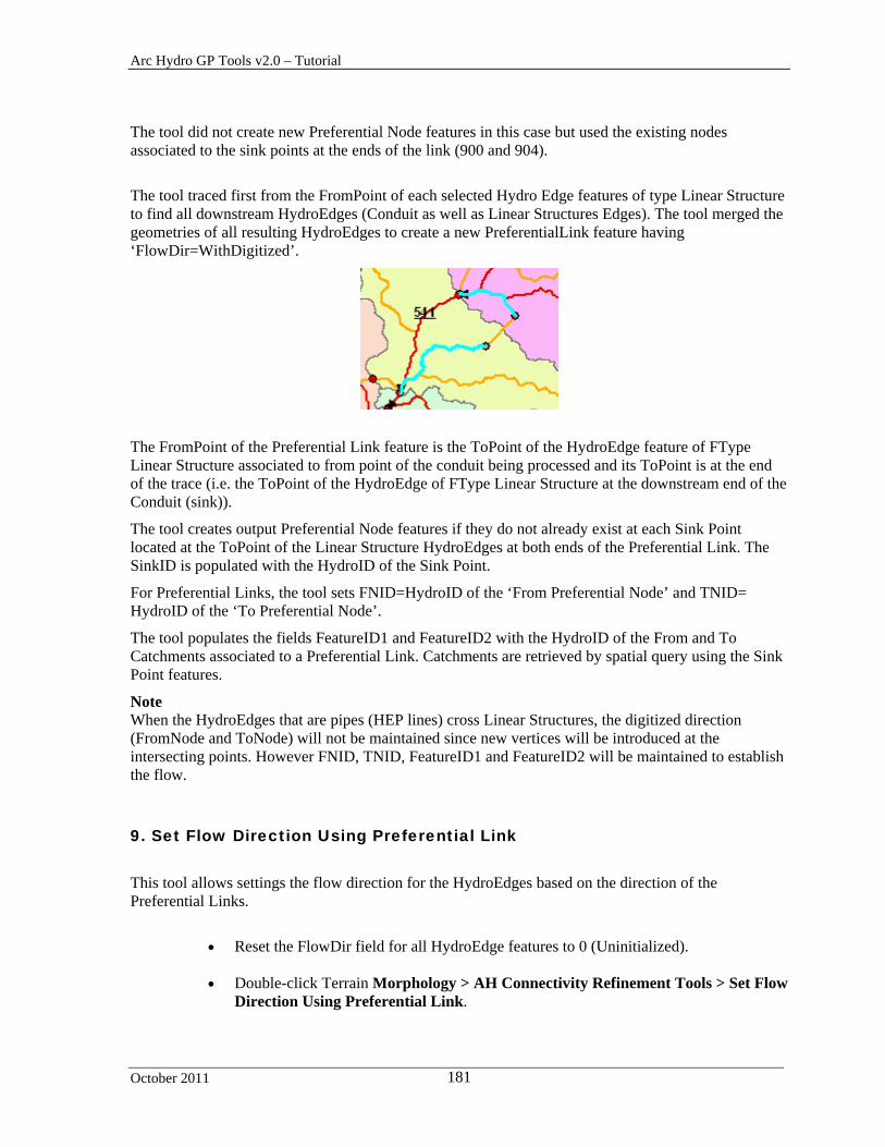
Arc Hydro GP Tools v2.0 – Tutorial
October 2011 181
The tool did not create new Preferential Node features in this case but used the existing nodes associated to the sink points at the ends of the link (900 and 904).
The tool traced first from the FromPoint of each selected Hydro Edge features of type Linear Structure to find all downstream HydroEdges (Conduit as well as Linear Structures Edges). The tool merged the geometries of all resulting HydroEdges to create a new PreferentialLink feature having ‘FlowDir=WithDigitized’.
The FromPoint of the Preferential Link feature is the ToPoint of the HydroEdge feature of FType Linear Structure associated to from point of the conduit being processed and its ToPoint is at the end of the trace (i.e. the ToPoint of the HydroEdge of FType Linear Structure at the downstream end of the Conduit (sink)).
The tool creates output Preferential Node features if they do not already exist at each Sink Point located at the ToPoint of the Linear Structure HydroEdges at both ends of the Preferential Link. The SinkID is populated with the HydroID of the Sink Point.
For Preferential Links, the tool sets FNID=HydroID of the ‘From Preferential Node’ and TNID= HydroID of the ‘To Preferential Node’.
The tool populates the fields FeatureID1 and FeatureID2 with the HydroID of the From and To Catchments associated to a Preferential Link. Catchments are retrieved by spatial query using the Sink Point features.
Note When the HydroEdges that are pipes (HEP lines) cross Linear Structures, the digitized direction (FromNode and ToNode) will not be maintained since new vertices will be introduced at the intersecting points. However FNID, TNID, FeatureID1 and FeatureID2 will be maintained to establish the flow.
9. Set Flow Direction Using Preferential Link
This tool allows settings the flow direction for the HydroEdges based on the direction of the Preferential Links.
Reset the FlowDir field for all HydroEdge features to 0 (Uninitialized).
Double-click Terrain Morphology > AH Connectivity Refinement Tools > Set Flow
Direction Using Preferential Link.
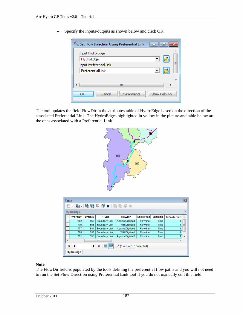
Arc Hydro GP Tools v2.0 – Tutorial
October 2011 182
Specify the inputs/outputs as shown below and click OK.
The tool updates the field FlowDir in the attributes table of HydroEdge based on the direction of the associated Preferential Link. The HydroEdges highlighted in yellow in the picture and table below are the ones associated with a Preferential Link.
Note The FlowDir field is populated by the tools defining the preferential flow paths and you will not need to run the Set Flow Direction using Preferential Link tool if you do not manually edit this field.
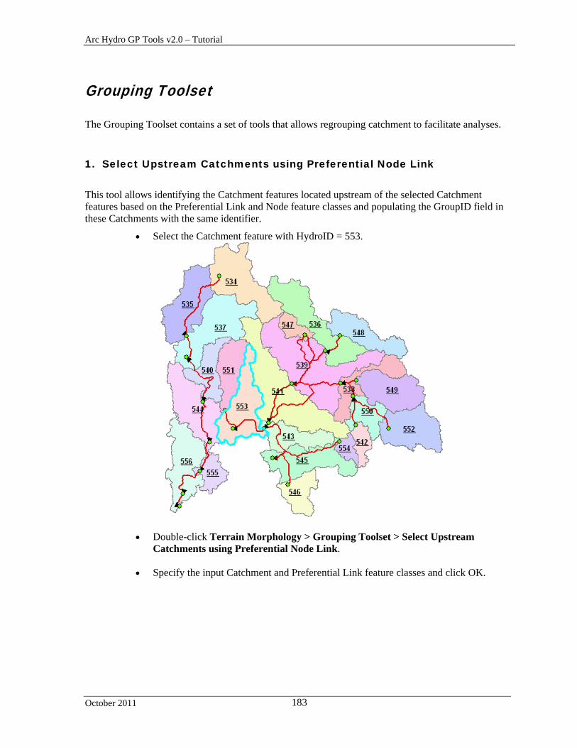
Arc Hydro GP Tools v2.0 – Tutorial
October 2011 183
Grouping Toolset
The Grouping Toolset contains a set of tools that allows regrouping catchment to facilitate analyses.
1. Select Upstream Catchments using Preferential Node Link
This tool allows identifying the Catchment features located upstream of the selected Catchment features based on the Preferential Link and Node feature classes and populating the GroupID field in these Catchments with the same identifier.
Select the Catchment feature with HydroID = 553.
Double-click Terrain Morphology > Grouping Toolset > Select Upstream Catchments using Preferential Node Link.
Specify the input Catchment and Preferential Link feature classes and click OK.
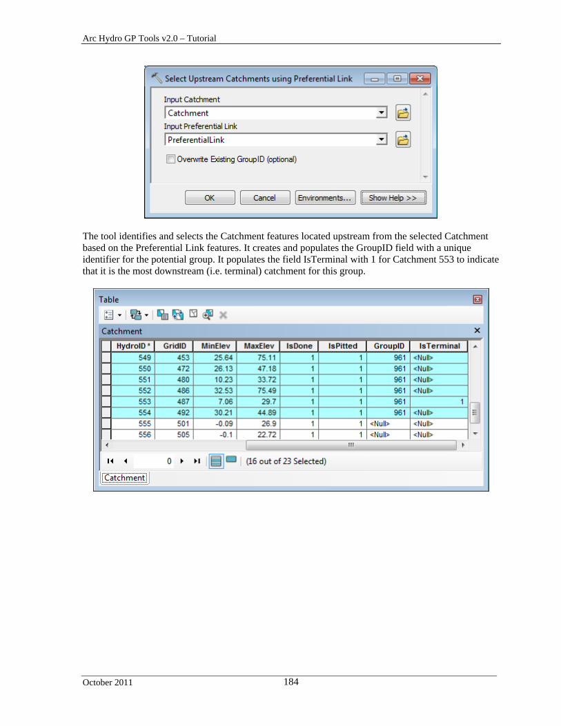
Arc Hydro GP Tools v2.0 – Tutorial
October 2011 184
The tool identifies and selects the Catchment features located upstream from the selected Catchment based on the Preferential Link features. It creates and populates the GroupID field with a unique identifier for the potential group. It populates the field IsTerminal with 1 for Catchment 553 to indicate that it is the most downstream (i.e. terminal) catchment for this group.

Arc Hydro GP Tools v2.0 – Tutorial
October 2011 185
Select the Catchment feature with HydroID 556 and rerun the function without the overwrite option).
The tool selects and populates the field GroupID for the remaining group.
.

Arc Hydro GP Tools v2.0 – Tutorial
October 2011 186
2. Group Selected Catchment
This tool allows manually modifying the GroupID attribute for the selected Catchments. This GroupID may have been assigned by the tool Select Upstream Catchments using Preferential Node/Link.
You are going to regroup the 4 Catchment features at the bottom right (HydroIDs 543, 545, 546 and 554).
Select these Catchments. They currently belong to group 961.

Arc Hydro GP Tools v2.0 – Tutorial
October 2011 187
Double-click Terrain Morphology > Grouping Toolset > Group Selected Catchments. Select Catchment as input Catchment feature class, check the Overwrite option since the GroupID field is already populated and click OK.

Arc Hydro GP Tools v2.0 – Tutorial
October 2011 188
The tool updates the field GroupID for the selected features and resets to Null the GroupID of the other features that had the same GroupID (936) before the update.
3. Ungroup Selected Catchments
This tool allows resetting the GroupID to Null for the selected Catchments.
Select the 4 Catchment features at the bottom right corner that have the field GroupID populated.
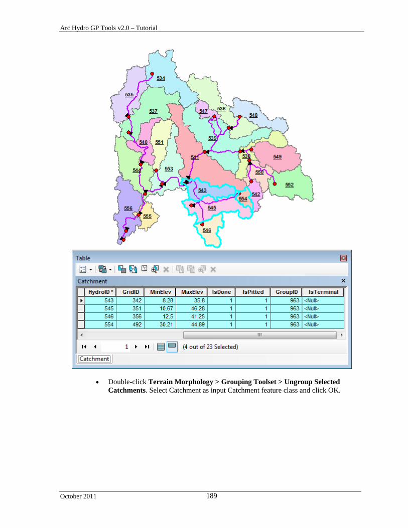
Arc Hydro GP Tools v2.0 – Tutorial
October 2011 189
Double-click Terrain Morphology > Grouping Toolset > Ungroup Selected Catchments. Select Catchment as input Catchment feature class and click OK.

Arc Hydro GP Tools v2.0 – Tutorial
October 2011 190
The tool resets the GroupID for the selected fields to Null.
4. Generate Group Basin
This tool allows dissolving Catchment features based on the GroupID attribute to create the output Group Basin polygon feature class.
Clear the selection and select the Catchment with HydroID 538 as shown below.

Arc Hydro GP Tools v2.0 – Tutorial
October 2011 191
Run the tool Select Upstream Catchments using Preferential Node Link without the overwrite option checked to repopulate the null GroupIDs for this group.
Repeat this operation after selecting first 541, then 543 and finally 553 with the option
to overwrite kept unchecked to populate the remaining GroupIDs.
Double-click Terrain Morphology > Grouping Toolset > Generate Group Basin.
The tool merges the Catchments having the same GroupID to create the output GroupBasin feature class. The HydroID field in the GroupBasin is populated with the GroupID from the Catchments belonging to the group and uniquely identifies the group. The tool populates the field IsPitted with 1 to indicate that the GroupBasin feature is deranged.

Arc Hydro GP Tools v2.0 – Tutorial
October 2011 192
The tool also populates the field IsTerminal with 1 for the Catchment and Sink Point features located at the downstream end of a group.

Arc Hydro GP Tools v2.0 – Tutorial
October 2011 193
5. Generate Group Junction
This tool allows generating Group Hydro Junctions associated to the Group Basins the same way Hydro Junctions are associated to Catchment. This tool will create 3 types of Group Hydro Junction features:
- Junction located on the Group Basin boundary usually associated to structures (Bridge, culvert, cross section, natural overflow).
- Hydro Junction associated to Group Basin sink point (e.g. terminal sink point) - Dendritic Hydro Junction within the Group Basin
Double-click Terrain Morphology > Grouping Toolset > Generate Group
Junction.
Specify the input Group Basin, Hydro Junction and Sink Point features, enter a name for the output Group Junction feature class and click OK.

Arc Hydro GP Tools v2.0 – Tutorial
October 2011 194
The tool processes each Group Basin feature in the input Group Basin feature class. For each Group Basin, it creates Group Hydro Junction for each structure located on its boundary, for its sink point and for each dendritic junction located within the Group Basin. In this example, the tool only creates 23 Group Junctions corresponding to the 5 identified terminal sinks in the input Sink Point feature class and 16 boundary nodes.

Arc Hydro GP Tools v2.0 – Tutorial
October 2011 195
6. Generate Group Link
This tool allows generating the Group Link and Group Node feature classes defining the preferred connectivity between Group Basin features.
Double-click Terrain Morphology > Grouping Toolset > Generate Group Link.
Specify the input Group Junction, Group Basin, Hydro Junction, Hydro Edge, Catchment and Preferential Link feature classes. Specify the name of the output Group Link and Group Node feature classes and click OK.
The tool generates the GroupLink and GroupNode feature classes storing the preferential links between the Group Basin features. It follows a 2 steps process to identify and generate the links:
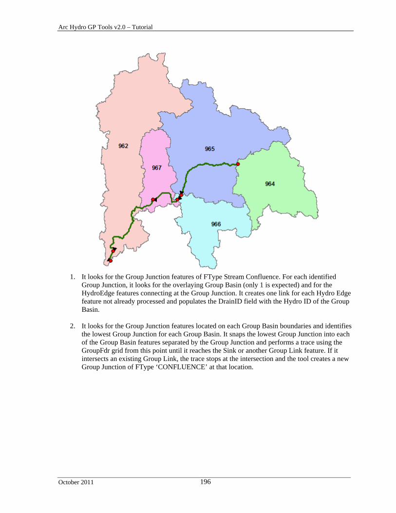
Arc Hydro GP Tools v2.0 – Tutorial
October 2011 196
1. It looks for the Group Junction features of FType Stream Confluence. For each identified
Group Junction, it looks for the overlaying Group Basin (only 1 is expected) and for the HydroEdge features connecting at the Group Junction. It creates one link for each Hydro Edge feature not already processed and populates the DrainID field with the Hydro ID of the Group Basin.
2. It looks for the Group Junction features located on each Group Basin boundaries and identifies
the lowest Group Junction for each Group Basin. It snaps the lowest Group Junction into each of the Group Basin features separated by the Group Junction and performs a trace using the GroupFdr grid from this point until it reaches the Sink or another Group Link feature. If it intersects an existing Group Link, the trace stops at the intersection and the tool creates a new Group Junction of FType ‘CONFLUENCE’ at that location.

Arc Hydro GP Tools v2.0 – Tutorial
October 2011 197
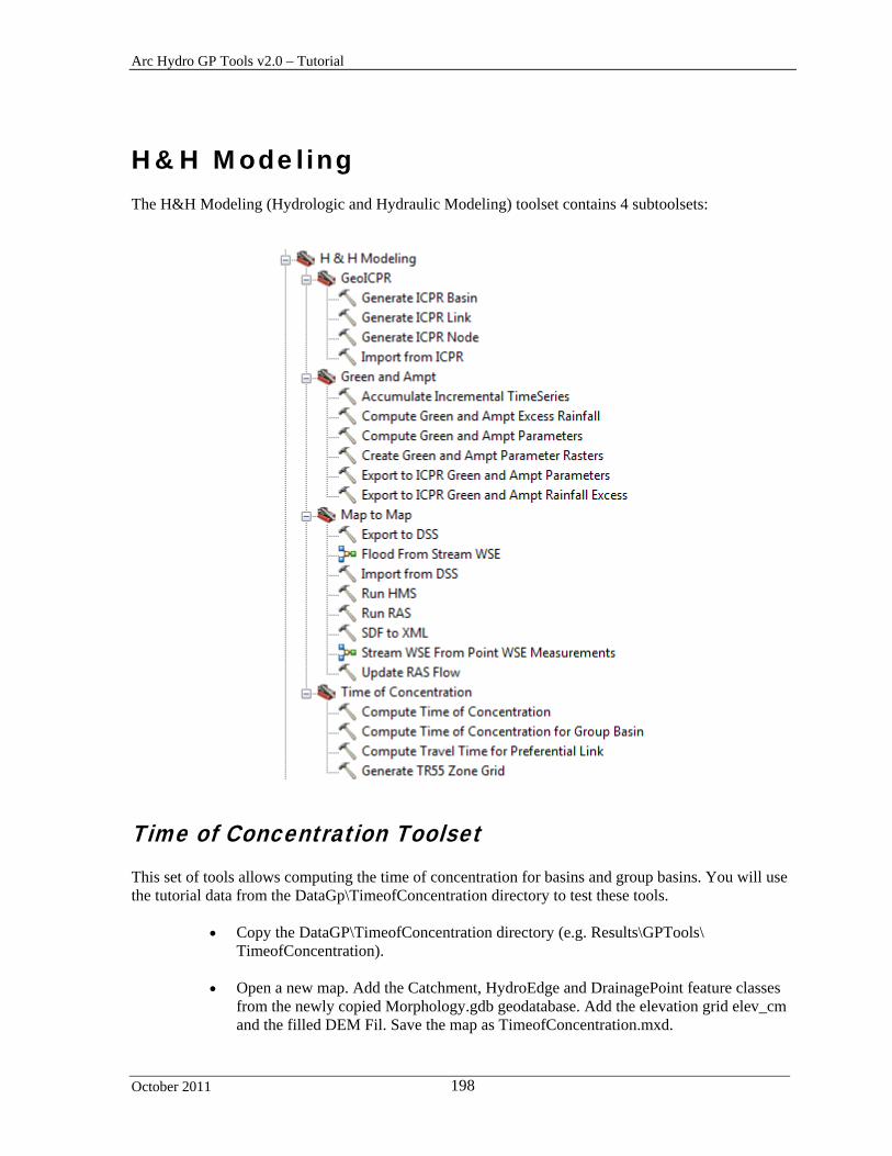
Arc Hydro GP Tools v2.0 – Tutorial
October 2011 198
H&H Modeling The H&H Modeling (Hydrologic and Hydraulic Modeling) toolset contains 4 subtoolsets:
Time of Concentration Toolset This set of tools allows computing the time of concentration for basins and group basins. You will use the tutorial data from the DataGp\TimeofConcentration directory to test these tools.
Copy the DataGP\TimeofConcentration directory (e.g. Results\GPTools\ TimeofConcentration).
Open a new map. Add the Catchment, HydroEdge and DrainagePoint feature classes
from the newly copied Morphology.gdb geodatabase. Add the elevation grid elev_cm and the filled DEM Fil. Save the map as TimeofConcentration.mxd.

Arc Hydro GP Tools v2.0 – Tutorial
October 2011 199
1. Generate TR55 Zone Grid
This tool generates the TR55 Zone Grid defining the way the water is moving across the land. This grid will be used as input by the tool Compute Time of Concentration. The tool will process all input drainage areas and set the extent using the input DEM grid. The input Hydro Edge feature class is optional. If specified, only the features having HYDROEDGE_HYDRAULIC_TYPE_DESC=’CHAN’ (CHANNEL) will be used to define Zone 3.
Double-click H&H Modeling > Time of Concentration > Generate TR55 Grid.
Specify the input Drainage Area feature class (e.g. Catchment) and the input DEM grid used to set the cell size and extent of the output grid. Enter the Overland Flow Distance in meters. Specify the optional HydroEdge feature class. Enter a name for the output TR55 Zone Grid. Click OK.
The tool generates the output TR55 Zone grid. There are no Channel Flow zone since the input HydroEdge feature class does not have any “CHANNEL” features.
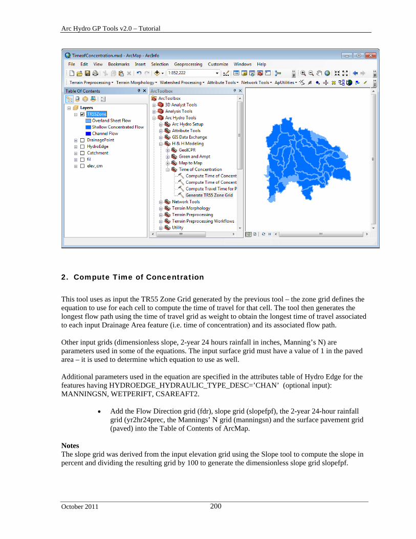
Arc Hydro GP Tools v2.0 – Tutorial
October 2011 200
2. Compute Time of Concentration
This tool uses as input the TR55 Zone Grid generated by the previous tool – the zone grid defines the equation to use for each cell to compute the time of travel for that cell. The tool then generates the longest flow path using the time of travel grid as weight to obtain the longest time of travel associated to each input Drainage Area feature (i.e. time of concentration) and its associated flow path. Other input grids (dimensionless slope, 2-year 24 hours rainfall in inches, Manning’s N) are parameters used in some of the equations. The input surface grid must have a value of 1 in the paved area – it is used to determine which equation to use as well. Additional parameters used in the equation are specified in the attributes table of Hydro Edge for the features having HYDROEDGE_HYDRAULIC_TYPE_DESC=’CHAN’ (optional input): MANNINGSN, WETPERIFT, CSAREAFT2.
Add the Flow Direction grid (fdr), slope grid (slopefpf), the 2-year 24-hour rainfall grid (yr2hr24prec, the Mannings’ N grid (manningsn) and the surface pavement grid (paved) into the Table of Contents of ArcMap.
Notes The slope grid was derived from the input elevation grid using the Slope tool to compute the slope in percent and dividing the resulting grid by 100 to generate the dimensionless slope grid slopefpf.
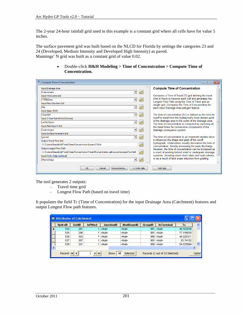
Arc Hydro GP Tools v2.0 – Tutorial
October 2011 201
The 2-year 24-hour rainfall grid used in this example is a constant grid where all cells have for value 5 inches. The surface pavement grid was built based on the NLCD for Florida by settings the categories 23 and 24 (Developed, Medium Intensity and Developed High Intensity) as paved. Mannings’ N grid was built as a constant grid of value 0.02.
Double-click H&H Modeling > Time of Concentration > Compute Time of Concentration.
The tool generates 2 outputs:
- Travel time grid - Longest Flow Path (based on travel time)
It populates the field Tc (Time of Concentration) for the input Drainage Area (Catchment) features and output Longest Flow path features.
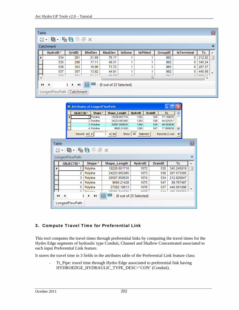
Arc Hydro GP Tools v2.0 – Tutorial
October 2011 202
3. Compute Travel Time for Preferential Link
This tool computes the travel times through preferential links by computing the travel times for the Hydro Edge segments of hydraulic type Conduit, Channel and Shallow Concentrated associated to each input Preferential Link feature.
It stores the travel time in 3 fields in the attributes table of the Preferential Link feature class:
- Tt_Pipe: travel time through Hydro Edge associated to preferential link having HYDROEDGE_HYDRAULIC_TYPE_DESC=’CON’ (Conduit).

Arc Hydro GP Tools v2.0 – Tutorial
October 2011 203
- Tt_Chan: travel time through Hydro Edge associated to preferential link having HYDROEDGE_HYDRAULIC_TYPE_DESC=’CHAN’ (Channel).
- Tt_Con: travel time through Hydro Edge associated to preferential link having
HYDROEDGE_HYDRAULIC_TYPE_DESC=’SC’ (shallow concentrated). Note The 3 time of travel fields will be populated with non zeros values only for the Preferential Links that are associated to HydroEdges of type Conduit, Channel or Shallow Concentrated. Hence the Preferential Links created with the function Define Overland Preferential Node Link Schema will always have the time of travels sets to 0.
Add the SinkPolygon and the Preferential Link feature class into the Table of Contents of ArcMap.
Double-click H&H Modeling > Time of Concentration > Compute Travel Time
for Preferential Link.
Specify the input Preferential Link, HydroEdge, and Sink Polygon feature classes as well as the input DEM and click OK.
You may get the following error: Paved field Paved not populated for shallow concentrated HydroEdge with OID=131 This tool requires that the field Paved be populated in the input HydroEdge feature class for the HydroEdge of hydraulic type Shallow Concentrated.
Populate the field paved with 1 to indicate that the area is developed and rerun the tool.
The field Tt_Con associated to the Shallow Concentrated edges is populated.

Arc Hydro GP Tools v2.0 – Tutorial
October 2011 204
4. Compute Time of Concentration for Group Basin
This tool computes the time of concentration for a Group Basin and generates the associated Group Longest Flow Path. The time of concentration is stored in the Tc field in both the input Group Basin features and the generated Group Longest Flow Path features. The tool works on a selected set of Group Basin features or on all features if there is no selected set. The Group Basin feature class must contain the field HydroID that relates to the field GroupID in the Catchment features, defining the Catchments that belong to a given Group Basin. In addition to GroupID, the Catchment feature class must also have the HydroID field used to relate to the Preferential Link features, the IsTerminal field that indicates whether the Catchment is terminal for the Group and the Tc field storing the time of concentration for the catchment computed with the tool Compute Time of Concentration. The input Preferential Link feature class must contain the fields FeatureID1 that identifies the origin Catchment and FeatureID2 that identifies the destination Catchment, as well as the fields Tt_Pipe, Tt_Con and Tt_Chan storing time of travels associated to the link. The time of travel fields are created and populated by the tool Compute Time of Travel for Preferential Link.
Add the GroupBasin feature class into the map.
Double-click H&H Modeling > Time of Concentration > Compute Time of Concentration for Group Basin.
Specify the input Group Basin, Catchment, Preferential Link and Longest Flow Path
feature classes and enter a name for the output Group Longest Flow Path feature class. Click OK.
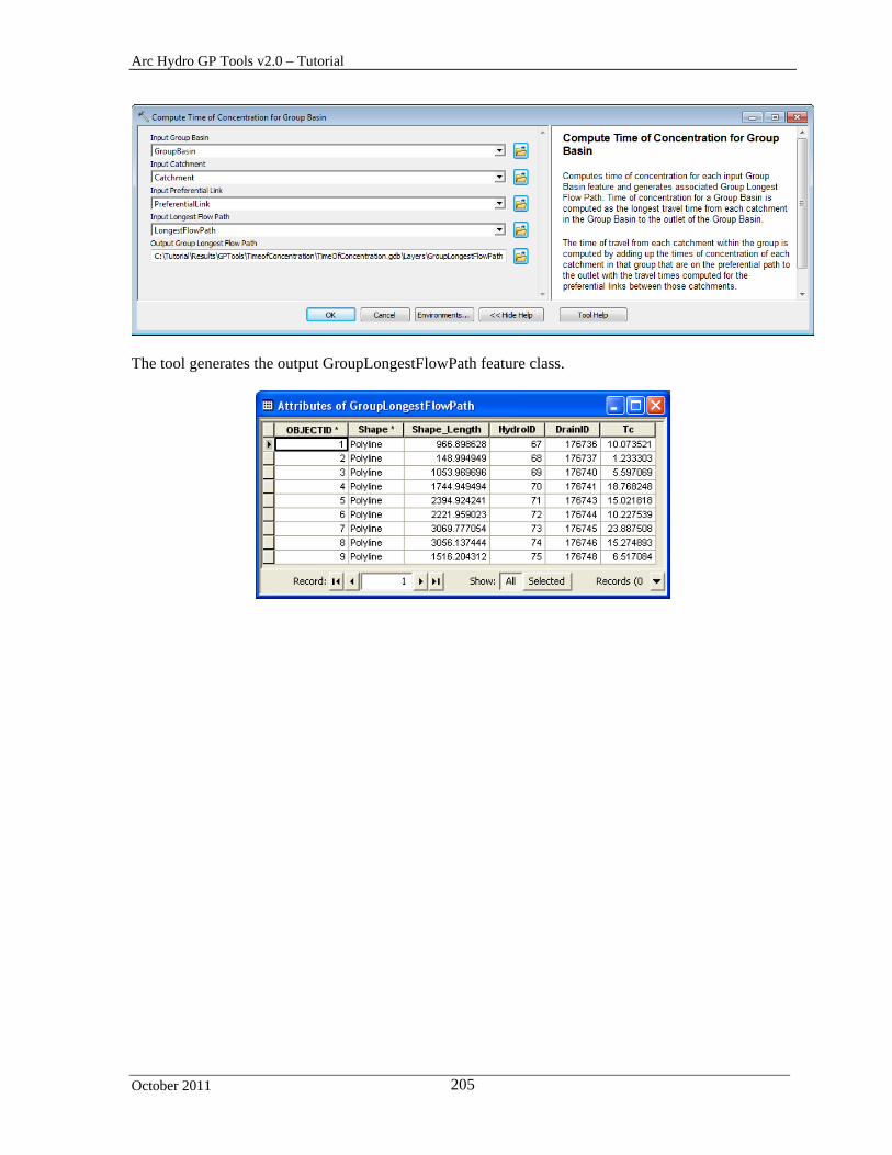
Arc Hydro GP Tools v2.0 – Tutorial
October 2011 205
The tool generates the output GroupLongestFlowPath feature class.

Arc Hydro GP Tools v2.0 – Tutorial
October 2011 206
The tool populates the Tc field in the Group Basin feature class.

Arc Hydro GP Tools v2.0 – Tutorial
October 2011 207
Arc Hydro GP Tools v2.0 – Tutorial
October 2011 208
Green and Ampt Toolset This toolset contains a set of tools supporting Green and Ampt modeling. You are going to use the data from the directory DataGP\GreenAmpt in this section.
Copy the data into your target directory (e.g. Results\GPTools\GreenAmpt).
Open a new map document and add the subwatershed feature class and the TimeSeries and VariableDefinition tables. Save the map as GreenAmpt.mxd.
1. Accumulate Incremental TimeSeries
This tool allows accumulating the time series steps from the input incremental time series associated to each input subwatershed feature. For each feature in the input Subwatershed feature class, the function retrieves the specified associated incremental time series steps for the requested interval. It accumulates the time steps and stores them as a new time series of the specified output type in the target time series table.
Double-click H&H Modeling > Accumulate Incremental TimeSeries.
Specify the Subwatershed feature class you want to process and its associated TimeSeries and VariableDefinition tables. The TimeSeries table stores the time series steps while the VariableDefinition table defines the available time series variables.
Specify the source and target TS Type IDs. The Source TS Type ID must be
associated to an incremental time series (i.e. DataType = Incremental in VariableDefinition table).
Specify the start and end date/time for the time series to accumulate (e.g. 1/1/2001 to
1/2/2001 for the tutorial data - cannot be left blank) as well as the target Time Series table and click OK.

Arc Hydro GP Tools v2.0 – Tutorial
October 2011 209
For each input subwatershed feature, the tool accumulates the incremental time steps of the specified type for the selected period and stores the accumulated steps in the target time series table.
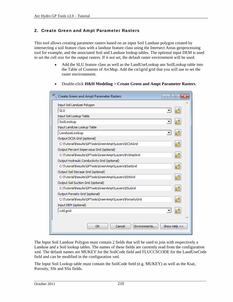
Arc Hydro GP Tools v2.0 – Tutorial
October 2011 210
2. Create Green and Ampt Parameter Rasters
This tool allows creating parameter rasters based on an input Soil Landuse polygon created by intersecting a soil feature class with a landuse feature class using the Intersect Areas geoprocessing tool for example, and the associated Soil and Landuse lookup tables. The optional input DEM is used to set the cell size for the output rasters. If it not set, the default raster environment will be used.
Add the SLU feature class as well as the LandUseLookup ans SoilLookup table into the Table of Contents of ArcMap. Add the cst1grid grid that you will use to set the raster environmnent.
Double-click H&H Modeling > Create Green and Ampt Parameter Rasters.
The Input Soil Landuse Polygon must contain 2 fields that will be used to join with respectively a Landuse and a Soil lookup tables. The names of these fields are currently read from the configuration xml. The default names are MUKEY for the SoilCode field and FLUCCSCODE for the LandUseCode field and can be modified in the configuration xml.
The Input Soil Lookup table must contain the SoilCode field (e.g. MUKEY) as well as the Ksat, Porosity, SSt and SSu fields.
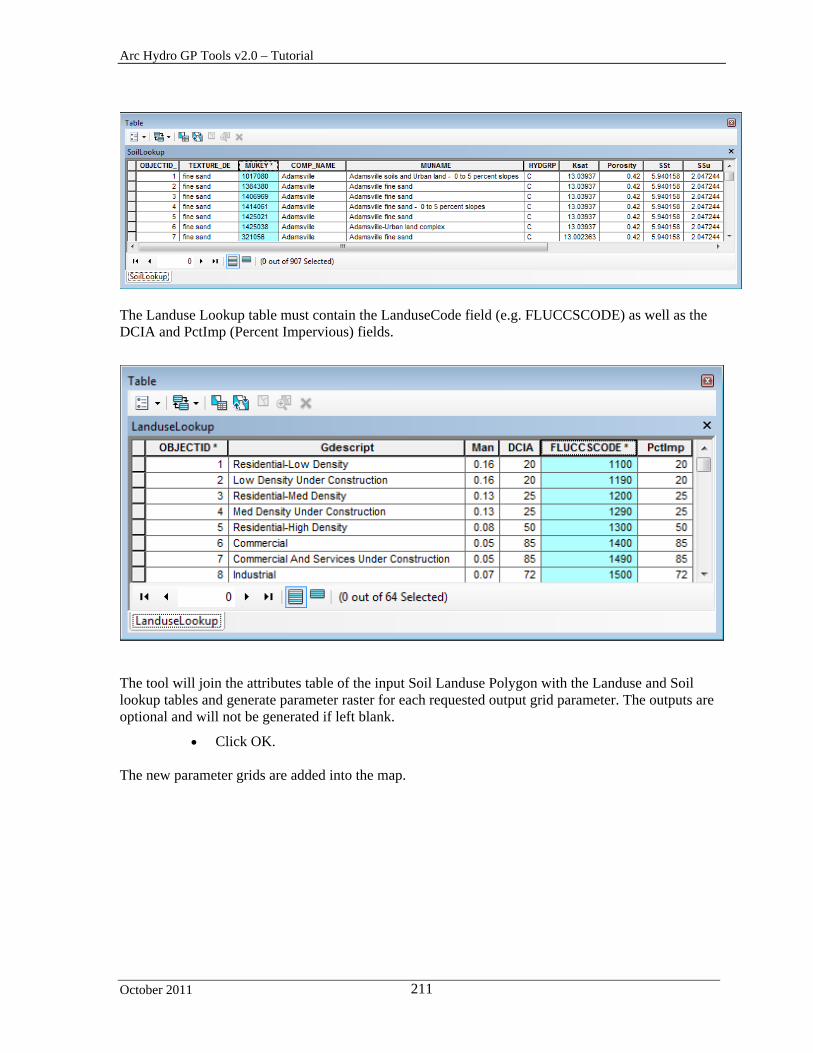
Arc Hydro GP Tools v2.0 – Tutorial
October 2011 211
The Landuse Lookup table must contain the LanduseCode field (e.g. FLUCCSCODE) as well as the DCIA and PctImp (Percent Impervious) fields.
The tool will join the attributes table of the input Soil Landuse Polygon with the Landuse and Soil lookup tables and generate parameter raster for each requested output grid parameter. The outputs are optional and will not be generated if left blank.
Click OK. The new parameter grids are added into the map.

Arc Hydro GP Tools v2.0 – Tutorial
October 2011 212

Arc Hydro GP Tools v 2.0 – Tutorial
October 2011 213
3. Compute Green and Ampt Parameters
This tool allows computing the Green and Ampt parameters for an input polygon feature class using the grids generated with the tool Create Green and Ampt Parameter Raster.
Double-click H&H Modeling > Compute Green and Ampt Parameters.
Select as Input Subwatershed the polygon feature class for which you want to populate the Green and Ampt parameters. This feature class must contain the HydroID field and it must be populated with unique values. Click OK.
The tool computes the average value of each requested parameter by performing a zonal statistics operation on each grid using HydroID to define the zones in the input Subwatershed feature class. The Green Ampt fields are created if they do not already exist and populated for each polygon feature.
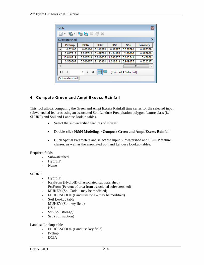
Arc Hydro GP Tools v2.0 – Tutorial
October 2011 214
4. Compute Green and Ampt Excess Rainfall
This tool allows computing the Green and Ampt Excess Rainfall time series for the selected input subwatershed features using an associated Soil Landuse Precipitation polygon feature class (i.e. SLURP) and Soil and Landuse lookup tables.
Select the subwatershed features of interest.
Double-click H&H Modeling > Compute Green and Ampt Excess Rainfall.
Click Spatial Parameters and select the input Subwatershed and SLURP feature classes, as well as the associated Soil and Landuse Lookup tables.
Required fields
- Subwatershed - HydroID - Name
SLURP
- HydroID - KeyFrom (HydroID of associated subwatershed) - PctFrom (Percent of area from associated subwatershed) - MUKEY (SoilCode – may be modified) - FLUCCSCODE (LandUseCode – may be modified) - Soil Lookup table - MUKEY (Soil key field) - KSat - Sst (Soil storage) - Ssu (Soil suction)
Landuse Lookup table
- FLUCCSCODE (Land use key field) - PctImp - DCIA
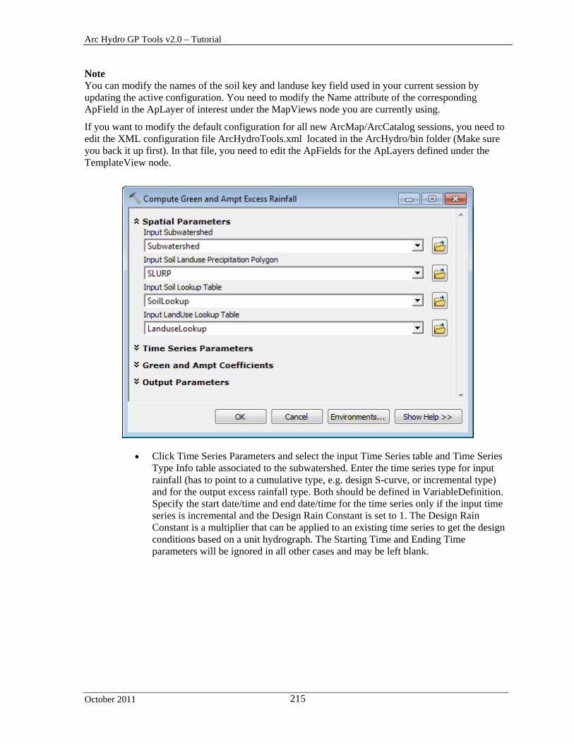
Arc Hydro GP Tools v2.0 – Tutorial
October 2011 215
Note You can modify the names of the soil key and landuse key field used in your current session by updating the active configuration. You need to modify the Name attribute of the corresponding ApField in the ApLayer of interest under the MapViews node you are currently using.
If you want to modify the default configuration for all new ArcMap/ArcCatalog sessions, you need to edit the XML configuration file ArcHydroTools.xml located in the ArcHydro/bin folder (Make sure you back it up first). In that file, you need to edit the ApFields for the ApLayers defined under the TemplateView node.
Click Time Series Parameters and select the input Time Series table and Time Series Type Info table associated to the subwatershed. Enter the time series type for input rainfall (has to point to a cumulative type, e.g. design S-curve, or incremental type) and for the output excess rainfall type. Both should be defined in VariableDefinition. Specify the start date/time and end date/time for the time series only if the input time series is incremental and the Design Rain Constant is set to 1. The Design Rain Constant is a multiplier that can be applied to an existing time series to get the design conditions based on a unit hydrograph. The Starting Time and Ending Time parameters will be ignored in all other cases and may be left blank.

Arc Hydro GP Tools v2.0 – Tutorial
October 2011 216
Click Green and Ampt Coefficients and enter the coefficients. The values specified will be saved in the parameters EffectivePorosityCoefficient, HydraulicConductivityCoefficient and EffectiveSaturationCoefficient under the ApFunction(GreenAmptCalculation) in the XML configuration associated with the map document in ArcMap. These values will be used by default the next time the tool is run.
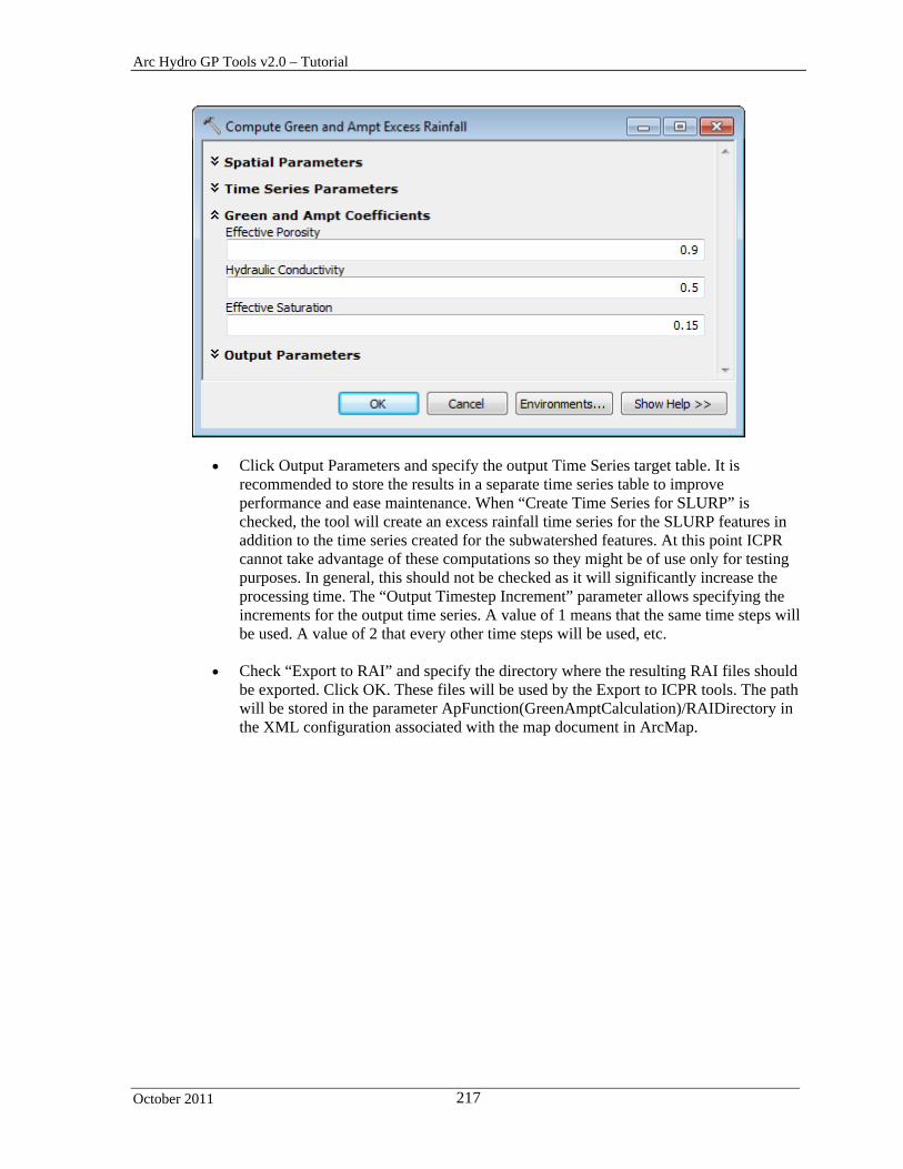
Arc Hydro GP Tools v2.0 – Tutorial
October 2011 217
Click Output Parameters and specify the output Time Series target table. It is recommended to store the results in a separate time series table to improve performance and ease maintenance. When “Create Time Series for SLURP” is checked, the tool will create an excess rainfall time series for the SLURP features in addition to the time series created for the subwatershed features. At this point ICPR cannot take advantage of these computations so they might be of use only for testing purposes. In general, this should not be checked as it will significantly increase the processing time. The “Output Timestep Increment” parameter allows specifying the increments for the output time series. A value of 1 means that the same time steps will be used. A value of 2 that every other time steps will be used, etc.
Check “Export to RAI” and specify the directory where the resulting RAI files should
be exported. Click OK. These files will be used by the Export to ICPR tools. The path will be stored in the parameter ApFunction(GreenAmptCalculation)/RAIDirectory in the XML configuration associated with the map document in ArcMap.
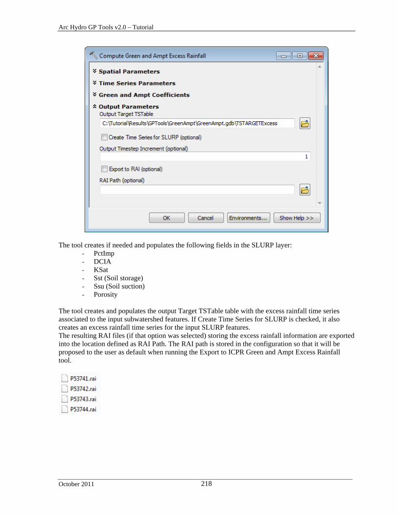
Arc Hydro GP Tools v2.0 – Tutorial
October 2011 218
The tool creates if needed and populates the following fields in the SLURP layer:
- PctImp - DCIA - KSat - Sst (Soil storage) - Ssu (Soil suction) - Porosity
The tool creates and populates the output Target TSTable table with the excess rainfall time series associated to the input subwatershed features. If Create Time Series for SLURP is checked, it also creates an excess rainfall time series for the input SLURP features. The resulting RAI files (if that option was selected) storing the excess rainfall information are exported into the location defined as RAI Path. The RAI path is stored in the configuration so that it will be proposed to the user as default when running the Export to ICPR Green and Ampt Excess Rainfall tool.

Arc Hydro GP Tools v2.0 – Tutorial
October 2011 219
Note The number of digits used for rounding the excess rainfall values is retrieved from the parameter ApFunction(GreenAmptCalculation)/RoundingConstant in the active configuration. The rounding defaults to 3.
5. Export to ICPR Green and Ampt Parameters
Warning This function works in ArcMap only. It does not work in ArcCatalog.
This tool creates the ICPR XML file required to run ICPR with the Green and Ampt option. This option uses RAI files storing information on rainfall, not excess rainfall (i.e. losses have not been taken into account). These RAI files may be created with the Export SCurve to RAI function available under Attribute Tools > Timer Series Processing. The Export tool will copy the files from the user-specified location.
Since the Green and Ampt computation will be performed by ICPR, the ICPR XML file must contain, in addition to information on the subwatersheds, data on the associated soils, landuses and precipitation.
Double-click H&H Modeling > Export to ICPR Green and Ampt Parameters.

Arc Hydro GP Tools v2.0 – Tutorial
October 2011 220
Specify the input Subwatershed feature class. It must contain the fields HydroID and Name.
Specify the associated input Soil Land Use Precipitation polygon as well as the Soil
and Landuse lookup tables. The SLURP polygon must contain the following fields:
- HydroID - KeyFrom - SoilCode (set by default to MUKEY) - LandUseCode (set by default to FLUCCSCODE) - PctImp
The Soil table must contain the following fields;
- SoilCode (set by default to MUKEY) - KSat - Sst (Soil storage) - Ssu (Soil suction) - Porosity
The Landuse table must contain the following fields:
- LandUseCode (set by default to FLUCCSCODE) - PctImp - DCIA
Specify the location of the RAI files previously generated. This location defaults to
the value of the parameter ApFunction(GreenAmptCalculation)/RAIDirectorySCurve in the configuration XML associated to the map document (if relevant).
Arc Hydro GP Tools v2.0 – Tutorial
October 2011 221
The tool retrieves the name of the control file for the export from the parameter ApFunction(GreenAmptCalculation)/ICPRExportControlGAParams in the active configuration. This file must exist in the ArcHydro/bin directory. It defaults to ICPRExportControlGAParams.xml.
The tool retrieves the name of the transformation file for the export from the parameter ApFunction(GreenAmptCalculation)/GWIS2ICPRXMLGAParams in the active configuration. This file must exist in the ArcHydro/bin directory. It defaults to GWIS2ICPRXMLGAParams.xsl
The tool generates the intermediate file GIS2ICPRTmpFileGAParams.xml as well as the output ICPR XML. It copies the RAI files into the RAI subdirectory located in the same location as the exported XML and saves the value of the RAI Path in the parameter ApFunction(GreenAmptCalculation)/RAIDirectorySCurve in the XML associated with the map document in ArcMap.
The tool sets the parameter ApFunction(GreenAmptCalculation)/XMLTargetDirectory to the export path for the XML.
Note The tool retrieves the 2 following Green and Ampt coefficient used to generate the Export XML from the active configuration:
- EffectivePorosityCoefficient - HydraulicConductivityCoefficient
6. Export to ICPR Green and Ampt Rainfall Excess
Warning This function works in ArcMap only. It does not work in ArcCatalog.
This tool creates the ICPR XML file required to run ICPR with the Impervious SCS option. Since the losses are computed using the Create Green and Ampt Excess Rainfall tool, the resulting excess rainfall stored in the .rai files is used in ICPR to run with the SCS option.
The export process will export the GIS data into an XML with the required structure for ICPR and will copy rai files previously generated into the target directory where the XML file is being generated.
Since the excess rainfall is going to be used as input into ICPR modeling, ICPR does NOT need to perform loss calculations. This will be accomplished by “tricking” ICPR by defining that each subwatershed has 100% DCIA. This also means that it is not necessary to export information for each SLURP, but just subwatershed information.
Double-click H&H Modeling > Export to ICPR Green and Ampt Rainfall Excess.

Arc Hydro GP Tools v2.0 – Tutorial
October 2011 222
Specify the input Subwatershed feature class and the location of the RAI files previously generated. This layer must contain the fields HydroID and Name.
Specify the path to the existing RAI files storing the associated excess rainfall. This
location defaults to the value of the parameter ApFunction(GreenAmptCalculation)/RAIDirectory.
Enter a path and name for the output ICPR XML file for Green and Ampt Excess Rain
and click OK. The tool retrieves the name of the control file for the export from the parameter ApFunction(GreenAmptCalculation)/ICPRExportControlGAExcess in the active configuration. This file must exist in the ArcHydro/bin directory. It defaults to ICPRExportControlGAExcess.xml.
The tool retrieves the name of the transformation file for the export from the parameter ApFunction(GreenAmptCalculation)/GWIS2ICPRXMLGAExcess in the active configuration. This file must exist in the ArcHydro/bin directory. It defaults to GWIS2ICPRXMLGAExcess.xsl
The tool generates the intermediate file GIS2ICPRTmpFileGAParams.xml as well as the output ICPR XML. It copies the rai files into the RAI subdirectory located in the same location as the exported XML and saves the value of the RAI Path in the parameter ApFunction(GreenAmptCalculation)/RAIDirectory in the XML associated with the map document in ArcMap.
The tool sets the parameter ApFunction(GreenAmptCalculation)/XMLTargetDirectory to the export path for the XML.

Arc Hydro GP Tools v2.0 – Tutorial
October 2011 223
Map to Map Toolset Prerequisites
- HEC-HMS - HEC-RAS - HEC-DSSVUE
Copy the DataGP\TimeSeries folder (e.g. into Results\GPTools\TimeSeries). Open a new ArcMap and add the super_radar_cal feature class and the TIMESERIES and VariableDefinition tables. Save the map document as DSS.mxd.
1. Export to DSS
This tool allows exporting time series data associated to input features of interest into the DSS format. The input feature class for which the time series needs to be exported must contain the name field.
Open the attributes table of super_radar_cal and select Options > Add Field.
Double-click H&H Modeling > Map to Map > Export to DSS.
Specify the inputs/outputs as shown below and click OK.
The tool generate the output DSS file (*.dss) and the gage file (.gage) if requested. The DSS file may be opened using the HEC-DSSVUE application that may be downloading from HEC web site.

Arc Hydro GP Tools v2.0 – Tutorial
October 2011 224
2. Import from DSS
This tool allows importing time series data in the DSS format into the Arc Hydro time series format in a geodatabase.
Double-click H&H Modeling > Map to Map > Import from DSS.
Specify the input Time Series layer. Select the super_radar_cal as TS Layer and its associated VariableDefinition table. Specify the type of time series variable to import and the source DSS File for import. Rename the output Time Series table TIMESERIESDSS and click OK.
The tool imports the requested data into a new time series table in the Arc Hydro format.
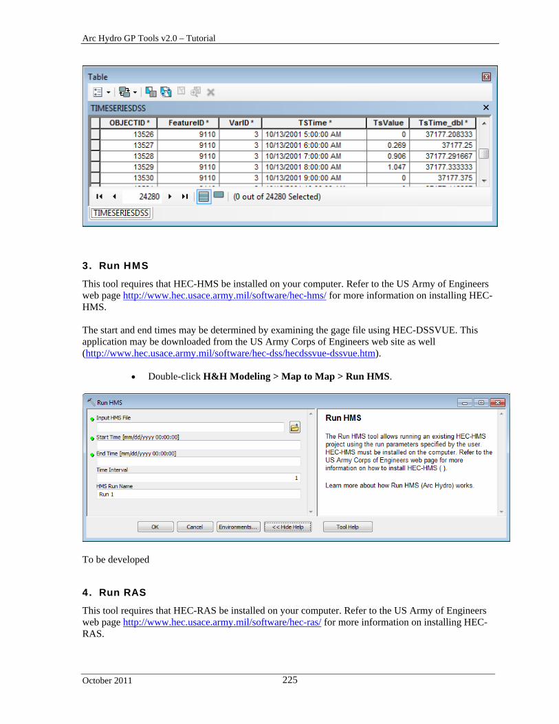
Arc Hydro GP Tools v2.0 – Tutorial
October 2011 225
3. Run HMS
This tool requires that HEC-HMS be installed on your computer. Refer to the US Army of Engineers web page http://www.hec.usace.army.mil/software/hec-hms/ for more information on installing HEC-HMS. The start and end times may be determined by examining the gage file using HEC-DSSVUE. This application may be downloaded from the US Army Corps of Engineers web site as well (http://www.hec.usace.army.mil/software/hec-dss/hecdssvue-dssvue.htm).
Double-click H&H Modeling > Map to Map > Run HMS.
To be developed
4. Run RAS
This tool requires that HEC-RAS be installed on your computer. Refer to the US Army of Engineers web page http://www.hec.usace.army.mil/software/hec-ras/ for more information on installing HEC-RAS.

Arc Hydro GP Tools v2.0 – Tutorial
October 2011 226
Double-click H&H Modeling > Map to Map > Run RAS.
To be developed
5. SDF to XML
This allows generating an .SDF file generated by HEC-GeoRAS into an XML file that can then be imported into a geodatabase.
Double-click H&H Modeling > Map to Map > SDF to XML.
Browse to the input SDF file to convert. Specify the name of the output XML file and click OK.
The tool generates an XML file than can be imported into a geodatabase.
6. Update RAS Flow
Double-click H&H Modeling > Map to Map > Update RAS Flow.
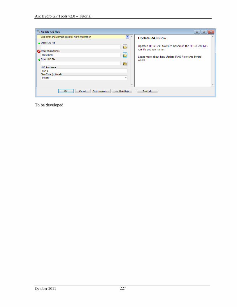
Arc Hydro GP Tools v2.0 – Tutorial
October 2011 227
To be developed

Arc Hydro GP Tools v2.0 – Tutorial
October 2011 228
GeoICPR Toolset This toolset allow preprocessing the data for the ICPR model and importing result from ICPR into ArcMap. This tool uses the data generated for deranged terrain. These tools worked on simplified (Group) features and require that the ICPR_Node and ICPR_Link feature classes already exist.
Copy the data from DatatGP\GeoICPR into your target location (e.g. Results\GPTools\GeoICPR).
Open a new map and add the GroupBasin, GroupNode, GroupLink, HydroEdge, and
HydroJunction feature classes into the map.
1. Generate ICPR Node
This tool allows generating ICPR Nodes based on input Group Node and Seed Point features. The Seed Point features may be created using the Create ICPR Seed Points tool available on the GeoICPR Tools toolbar installed with the Arc Hydro tools. You are going to create this feature class by exporting the GroupJunction of type NO (Natural Overflow) that intersects Group Link features.
Click Selection > Select by Location… and specify the following parameters.

Arc Hydro GP Tools v2.0 – Tutorial
October 2011 229
Click Selection > Select by Attributes… and specify the following parameters. Make sure the Method is set to “Select from current selection.”
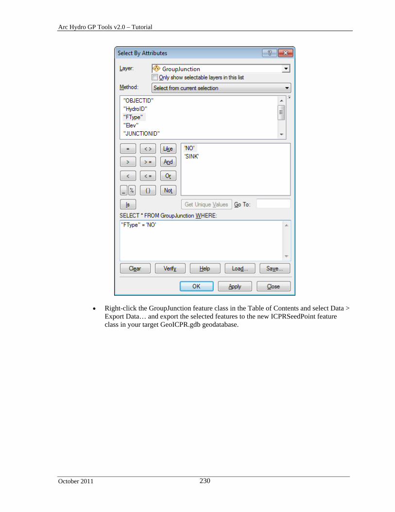
Arc Hydro GP Tools v2.0 – Tutorial
October 2011 230
Right-click the GroupJunction feature class in the Table of Contents and select Data > Export Data… and export the selected features to the new ICPRSeedPoint feature class in your target GeoICPR.gdb geodatabase.
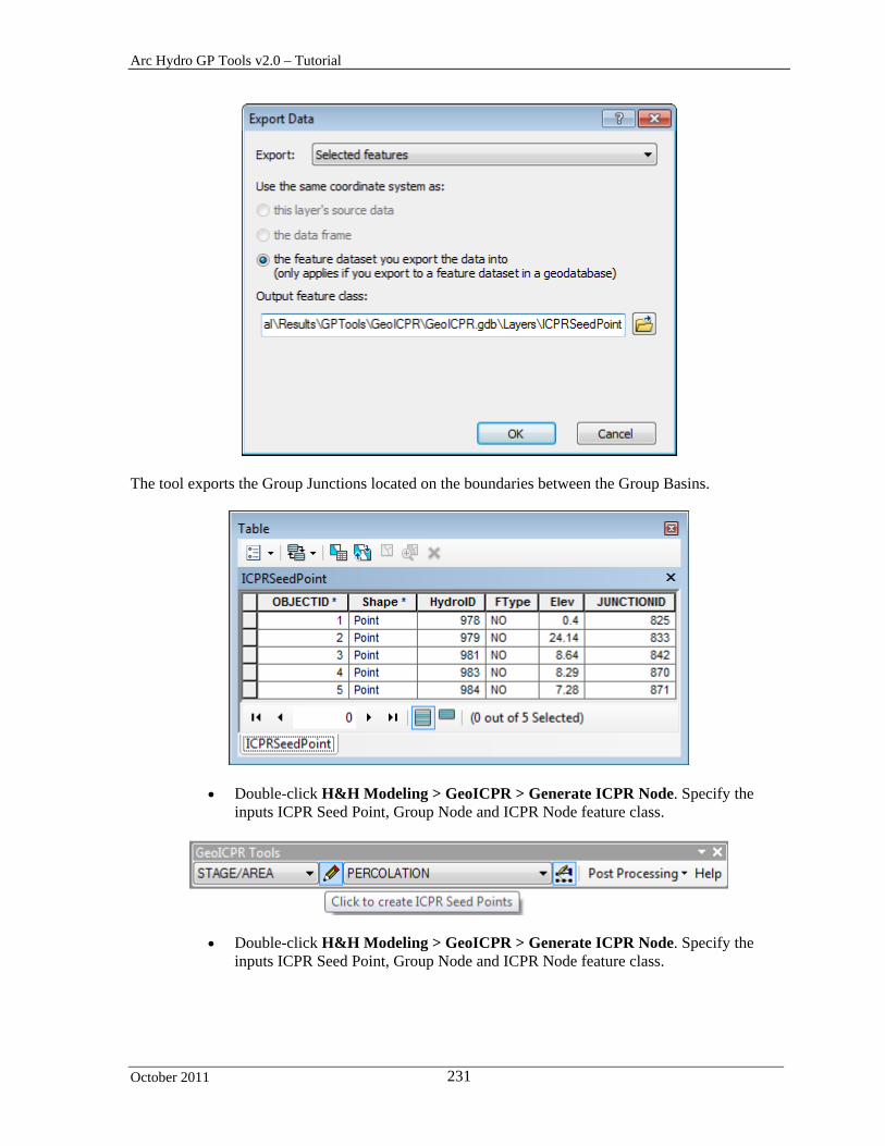
Arc Hydro GP Tools v2.0 – Tutorial
October 2011 231
The tool exports the Group Junctions located on the boundaries between the Group Basins.
Double-click H&H Modeling > GeoICPR > Generate ICPR Node. Specify the inputs ICPR Seed Point, Group Node and ICPR Node feature class.
Double-click H&H Modeling > GeoICPR > Generate ICPR Node. Specify the inputs ICPR Seed Point, Group Node and ICPR Node feature class.

Arc Hydro GP Tools v2.0 – Tutorial
October 2011 232
The tool displays an error message indicating that the field TYPE is missing in the input ICPRSeedPoint feature class.
Add the field TYPE as text to the ICPRSeedPoint feature class and populate it with WEIR for all features.

Arc Hydro GP Tools v2.0 – Tutorial
October 2011 233
Double-click H&H Modeling > GeoICPR > Generate ICPR Node. Specify the
inputs ICPR Seed Point, Group Node and ICPR Node feature class. The tool generates ICPR Node features associated to the ICPR Seed Points of type WEIR and to the Group Node. (STAGE/AREA).
2. Generate ICPR Link
This tool allows generating ICPR Link features defining the connectivity between Group Basins. ICPR Links are generated in the following cases:
Double-click H&H Modeling > GeoICPR > Generate ICPR Link.

Arc Hydro GP Tools v2.0 – Tutorial
October 2011 234
The tool generates 5 WEIR ICPR Link associated to the 3 WEIR ICPR Seed Point features.

Arc Hydro GP Tools v2.0 – Tutorial
October 2011 235
3. Generate ICPR Basin
This tool allows generating ICPR Group Basins based on STAGE/AREA ICPR Nodes and Channel ICPR Links.
Add the Catchment, Preferential Link, ICPR Basin feature classes and the flow direction grid.
Double-click H&H Modeling > GeoICPR > Generate ICPR Basin and specify the
inputs as shown in the picture below.

Arc Hydro GP Tools v2.0 – Tutorial
October 2011 236
The tool generates ICPR Basin for each STAGE/AREA ICPR Nodes. Since there are no ICPR Links of type Channel, the resulting ICPR Basin features are identical to the input Group Basin features. Note that there 2 identical ICPR Basins corresponding to Group Basin 962, one associated to the Group Sink and the other to the terminal boundary node.
Create a new ICPR Seed Point of type channel on one of the Group Link features. Make the GeoICPR Tools toolbar visible, select CHANNEL in the left dropdown list and click the Create ICPR Seed Points tool.
Specify the input HydroEdge and HydroJunction feature classes if prompted and click on one of the existing GroupLink to create a new ICPRSeedPoint feature of type Channel.
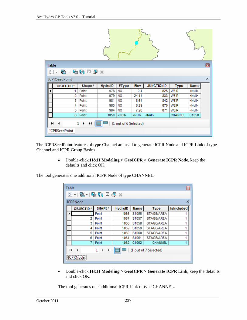
Arc Hydro GP Tools v2.0 – Tutorial
October 2011 237
The ICPRSeedPoint features of type Channel are used to generate ICPR Node and ICPR Link of type Channel and ICPR Group Basins.
Double-click H&H Modeling > GeoICPR > Generate ICPR Node, keep the defaults and click OK.
The tool generates one additional ICPR Node of type CHANNEL.
Double-click H&H Modeling > GeoICPR > Generate ICPR Link, keep the defaults and click OK.
The tool generates one additional ICPR Link of type CHANNEL.
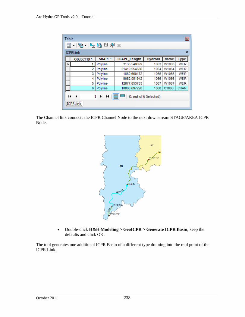
Arc Hydro GP Tools v2.0 – Tutorial
October 2011 238
The Channel link connects the ICPR Channel Node to the next downstream STAGE/AREA ICPR Node.
Double-click H&H Modeling > GeoICPR > Generate ICPR Basin, keep the defaults and click OK.
The tool generates one additional ICPR Basin of a different type draining into the mid point of the ICPR Link.

Arc Hydro GP Tools v2.0 – Tutorial
October 2011 239
The ICPR Basin features with HydroIDs 1105 and 1106, displayed in red, are identical. One is associatedto the Group Basin sink and the other to the terminal boundary node.

Arc Hydro GP Tools v2.0 – Tutorial
October 2011 240
4. Export to ICPR
After generating the data required by ICPR, this data can be exported into the input files required by ICPR using the tool Export GIS Data to XML available in the GIS Data Exchange Toolset.
5. Import from ICPR
This tool allows importing results from ICPR into geodatabase tables.
Double-click H&H Modeling > GeoICPR > Import from ICPR and specify the input Model Result Location. Select the input Variable Definition table. Keep the default for the output tables and click OK.
The tool imports the results from the ICPR run into the output tables.

Arc Hydro GP Tools v2.0 – Tutorial
October 2011 241
GIS Data Exchange
XML Exchange Toolset
The GIS Data Exchange toolset contains a set of tools that allow importing/exporting data between a geodatabase and an XML file. For additional information of these tools and their configuration, refer to the document XML Based Spatial Data Exchange User’s Guide.
You will export a small geodatabase containing feature classes and tables as an example using tutorial data and control files.
Copy the directory DataGP\GISDataExchange. This directory contains a sample geodatabase and control files that will be used for the export/import.
Open a new map document and add the Watershed and WatershedPoint feature classes into the map. Save the map as Export.mxd for example.
1. Export GIS Data to XML
This tool allows exporting layers and tables from the map document or from a geodatabase on the disk into an output XML file based on a configuration file.
Double-click GIS Data Exchange > Export GIS Data to XML.
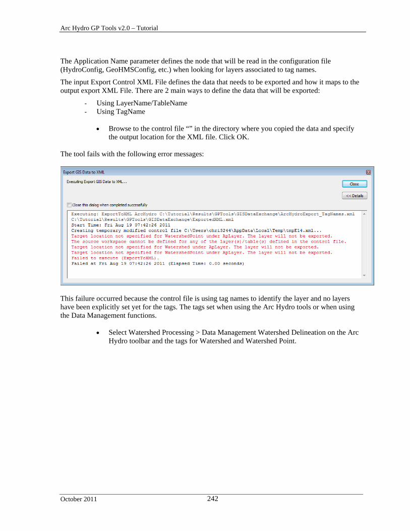
Arc Hydro GP Tools v2.0 – Tutorial
October 2011 242
The Application Name parameter defines the node that will be read in the configuration file (HydroConfig, GeoHMSConfig, etc.) when looking for layers associated to tag names.
The input Export Control XML File defines the data that needs to be exported and how it maps to the output export XML File. There are 2 main ways to define the data that will be exported:
- Using LayerName/TableName - Using TagName
Browse to the control file “” in the directory where you copied the data and specify
the output location for the XML file. Click OK. The tool fails with the following error messages:
This failure occurred because the control file is using tag names to identify the layer and no layers have been explicitly set yet for the tags. The tags set when using the Arc Hydro tools or when using the Data Management functions.
Select Watershed Processing > Data Management Watershed Delineation on the Arc Hydro toolbar and the tags for Watershed and Watershed Point.
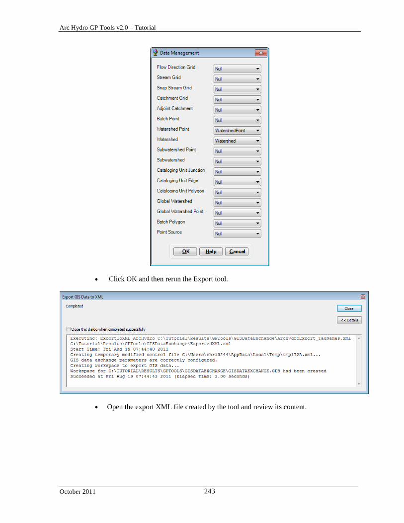
Arc Hydro GP Tools v2.0 – Tutorial
October 2011 243
Click OK and then rerun the Export tool.
Open the export XML file created by the tool and review its content.

Arc Hydro GP Tools v2.0 – Tutorial
October 2011 244
You are now going to export additional information on the feature classes so that the resulting XML can be transformed and imported back into a new geodatabase.
2. Import from XML
This tool allows importing data from an XML file that meets Esri geodatabase XML schema into a geodatabase. This formatted XML file may be generated by using the tool Transform XML.
Double-click GIS Data Exchange > Import from XML.
Browse to the input XML file meeting Esri geodatabase schema and specify the name of the new output file geodatabase. Click OK.
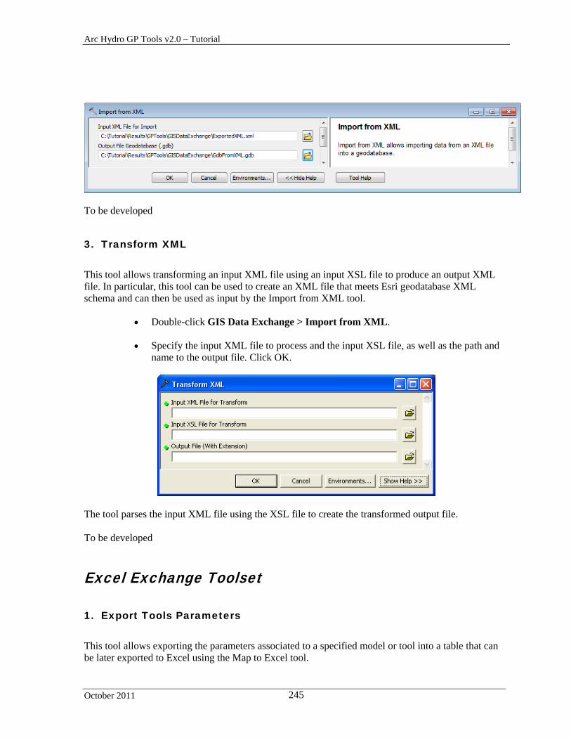
Arc Hydro GP Tools v2.0 – Tutorial
October 2011 245
To be developed
3. Transform XML
This tool allows transforming an input XML file using an input XSL file to produce an output XML file. In particular, this tool can be used to create an XML file that meets Esri geodatabase XML schema and can then be used as input by the Import from XML tool.
Double-click GIS Data Exchange > Import from XML.
Specify the input XML file to process and the input XSL file, as well as the path and name to the output file. Click OK.
The tool parses the input XML file using the XSL file to create the transformed output file.
To be developed
Excel Exchange Toolset
1. Export Tools Parameters
This tool allows exporting the parameters associated to a specified model or tool into a table that can be later exported to Excel using the Map to Excel tool.

Arc Hydro GP Tools v2.0 – Tutorial
October 2011 246
Double-click GIS Data Exchange > Export Tool Parameters.
Browse to the input model or tool whose parameters you want to export to a table (e.g.
DEM Reconditioning in the Arc Hydro Tools toolbox and in the Terrain Preprocessing toolset. Keep the default for the output table and click OK.
The tool creates the output table and generates one record for each parameter in the input tool/model that lists the location of the toolbox, the name of the tool, the name of the parameter, whether it is an input or output, its type and its current value.
2. Map to Excel
The Map to Excel tool allows exporting user specified attributes from tables/featureclasses within ArcMap to an Excel spreadsheet. This tool will also export the attributes from input/output layers after execution of the model. The configuration for the export process (name of the worksheet, range, cell etc) is predefined in a configuration XML.
Double-click GIS Data Exchange > Map to Excel. A function in Arc Hydro has a configuration associated with that function and it becomes part of the mxd as embedded XML resource. Figure 4 shows the configuration xml in the mxd (Run ArcHydro Tools tool bar->ApUtilities->XML Manager to display configuration XML).

Arc Hydro GP Tools v2.0 – Tutorial
October 2011 247
Figure 4: XML Configuration defined for each Arc Hydro Function under ApFunctions node.
Figure 5: ‘MapToExcel’ tool Configuration XML. Configuration for ‘Map to Excel’ tool is shown below. The rules for configuring the spreadsheet for Map to Excel are:

Arc Hydro GP Tools v2.0 – Tutorial
October 2011 248
1. The tool will only export to a single to file (WorkBook node) at a time. 2. Each model can export to separate work sheets (WorkSheets->WorksSheet
nodes) in the same file. 3. Each worksheet has its own configuration for exporting tables/layers
(WorkSheets->WorksSheet->ApLayers nodes). 4. Each worksheet has a list of macros that will be run after exporting to Excel
(WorkSheets->WorksSheet->RunMacros nodes). User can edit the xml node by right clicking ‘Edit Attributes’ or ‘Edit text’. User can also copy/paste/delete existing node to add/remove export elements. If you are not familiar with the ApLayer/ApField properties, please consult the additional document on Arc Hydro XML Manager. Typically, users are allowed to edit Name/AliasName and AdditionalParams properties. In the figure below, AdditionalParams is R=4;C=6 which means, the value of the field ‘PARAMVALUE’ is going to a cell with Row = 4 and Column = 6.
Figure 6: Editing the configuration XML for Map to Excel.
Figure 7: UI for the ‘Map to Excel’ tool when run as a standalone tool.
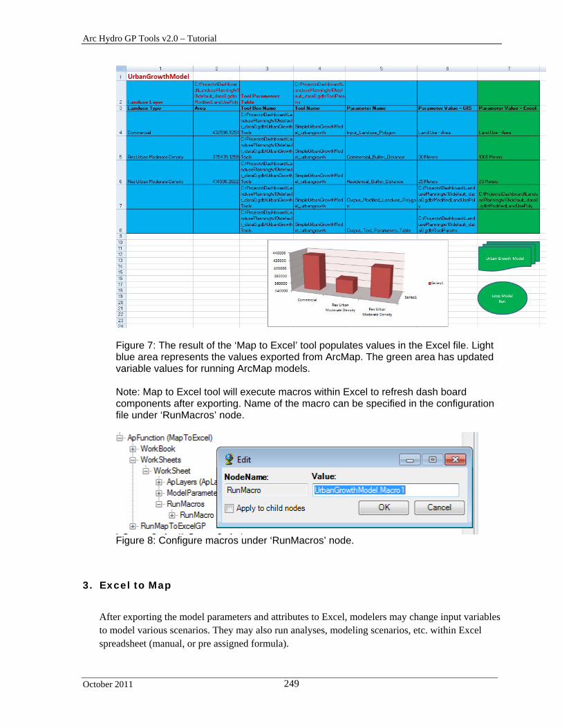
Arc Hydro GP Tools v2.0 – Tutorial
October 2011 249
Figure 7: The result of the ‘Map to Excel’ tool populates values in the Excel file. Light blue area represents the values exported from ArcMap. The green area has updated variable values for running ArcMap models. Note: Map to Excel tool will execute macros within Excel to refresh dash board components after exporting. Name of the macro can be specified in the configuration file under ‘RunMacros’ node.
Figure 8: Configure macros under ‘RunMacros’ node.
3. Excel to Map
After exporting the model parameters and attributes to Excel, modelers may change input variables to model various scenarios. They may also run analyses, modeling scenarios, etc. within Excel spreadsheet (manual, or pre assigned formula).
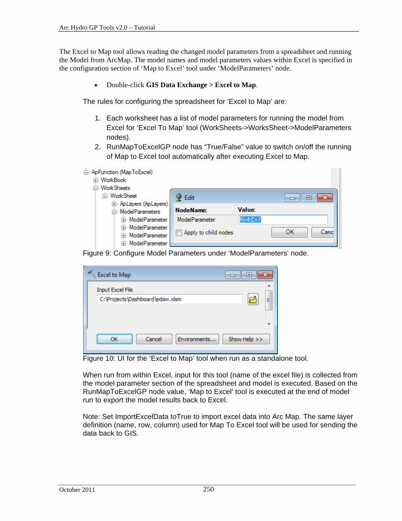
Arc Hydro GP Tools v2.0 – Tutorial
October 2011 250
The Excel to Map tool allows reading the changed model parameters from a spreadsheet and running the Model from ArcMap. The model names and model parameters values within Excel is specified in the configuration section of ‘Map to Excel’ tool under ‘ModelParameters’ node.
Double-click GIS Data Exchange > Excel to Map. The rules for configuring the spreadsheet for ‘Excel to Map’ are:
1. Each worksheet has a list of model parameters for running the model from Excel for ‘Excel To Map’ tool (WorkSheets->WorksSheet->ModelParameters nodes).
2. RunMapToExcelGP node has “True/False” value to switch on/off the running of Map to Excel tool automatically after executing Excel to Map.
Figure 9: Configure Model Parameters under ‘ModelParameters’ node.
Figure 10: UI for the ‘Excel to Map’ tool when run as a standalone tool. When run from within Excel, input for this tool (name of the excel file) is collected from the model parameter section of the spreadsheet and model is executed. Based on the RunMapToExcelGP node value, ‘Map to Excel’ tool is executed at the end of model run to export the model results back to Excel. Note: Set ImportExcelData toTrue to import excel data into Arc Map. The same layer definition (name, row, column) used for Map To Excel tool will be used for sending the data back to GIS.
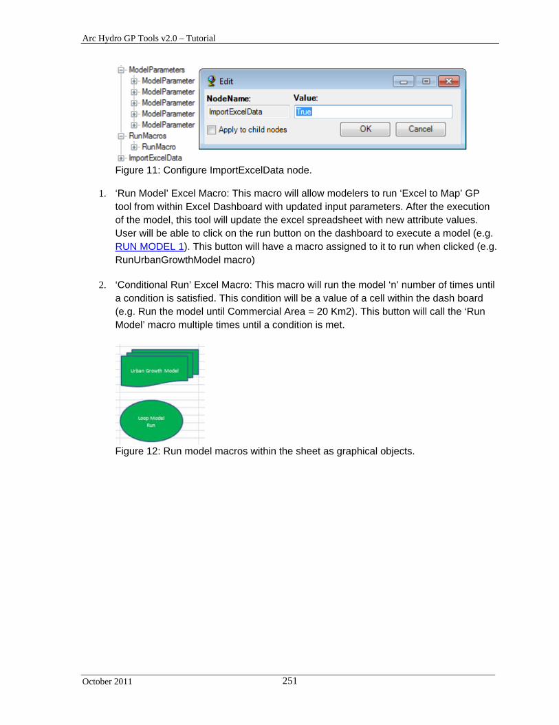
Arc Hydro GP Tools v2.0 – Tutorial
October 2011 251
Figure 11: Configure ImportExcelData node.
1. ‘Run Model’ Excel Macro: This macro will allow modelers to run ‘Excel to Map’ GP tool from within Excel Dashboard with updated input parameters. After the execution of the model, this tool will update the excel spreadsheet with new attribute values. User will be able to click on the run button on the dashboard to execute a model (e.g. RUN MODEL 1). This button will have a macro assigned to it to run when clicked (e.g. RunUrbanGrowthModel macro)
2. ‘Conditional Run’ Excel Macro: This macro will run the model ‘n’ number of times until a condition is satisfied. This condition will be a value of a cell within the dash board (e.g. Run the model until Commercial Area = 20 Km2). This button will call the ‘Run Model’ macro multiple times until a condition is met.
Figure 12: Run model macros within the sheet as graphical objects.